1
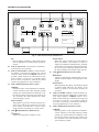
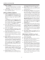
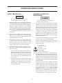
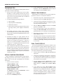
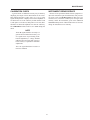
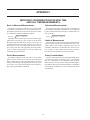
+ PRECISION
BK
INSTRUCTION
MANUAL
®
MODEL 2522B
20 MHz DIGITAL STORAGE/ANALOG
OSCILLOSCOPE
BK PRECISION
+
®
TEST INSTRUMENT SAFETY
WARNING
Normal use of test equipment exposes you to a certain amount of danger from electrical shock because
testing must often be performed where exposed high voltage is present. An electrical shock causing
10 milliamps of current to pass through the heart will stop most human heartbeats. Voltage as low as 35 volts
dc or ac rms should be considered dangerous and hazardous since it can produce a lethal current under
certain conditions. Higher voltage poses an even greater threat because such voltage can more easily
produce a lethal current. Your normal work habits should include all accepted practices that will prevent
contact with exposed high voltage, and that will steer current away from your heart in case of accidental
contact with a high voltage. You will significantly reduce the risk factor if you know and observe the
following safety precautions:
1. Don’t expose high voltage needlessly in the equipment under test. Remove housings and covers only when necessary.
Turn off equipment while making test connections in high-voltage circuits. Discharge high-voltage capacitors after
removing power.
2. If possible, familiarize yourself with the equipment being tested and the location of its high voltage points. However,
remember that high voltage may appear at unexpected points in defective equipment.
3. Use an insulated floor material or a large, insulated floor mat to stand on, and an insulated work surface on which to
place equipment; make certain such surfaces are not damp or wet.
4. Use the time-proven “one hand in the pocket” technique while handling an instrument probe. Be particularly careful to
avoid contacting a nearby metal object that could provide a good ground return path.
5. When using a probe, touch only the insulated portion. Never touch the exposed tip portion.
6. When testing ac powered equipment, remember that ac line voltage is usually present on some power input circuits such
as the on-off switch, fuses, power transformer, etc. any time the equipment is connected to an ac outlet, even if the
equipment is turned off.
7. Some equipment with a two-wire ac power cord, including some with polarized power plugs, is the “hot chassis” type.
This includes most recent television receivers and audio equipment. A plastic or wooden cabinet insulates the chassis
to protect the customer. When the cabinet is removed for servicing, a serious shock hazard exists if the chassis is touched.
Not only does this present a dangerous shock hazard, but damage to test instruments or the equipment under test may
result from connecting the ground lead of most test instruments (including this oscilloscope) to a “hot chassis”. To make
measurements in “hot chassis” equipment, always connect an isolation transformer between the ac outlet and the
equipment under test. The B+K Precision Model TR-110 or 1604A Isolation Transformer, or Model 1653A or 1655A
AC Power Supply is suitable for most applications. To be on the safe side, treat all two wire ac powered equipment as
“hot chassis” unless you are sure it has an isolated chassis or an earth ground chassis.
8. Never work alone. Someone should be nearby to render aid if necessary. Training in CPR (cardio-pulmonary
resuscitation) first aid is highly recommended.
Instruction Manual
for
+
BK
PRECISION
®
Model 2522B
20 MHz
Digital Storage/Analog
Oscilloscope
©2000 B+K Precision Corp.
This symbol on oscilloscope means “refer to instruction manual
for further precautionary information”. This symbol appears in the
manual where the corresponding information is given.
+
®
1031 Segovia Circle, Placentia, CA 92870
TABLE OF CONTENTS
Page
Page
OPERATING INSTRUCTIONS (Continued)
TEST INSTRUMENT SAFETY . . . . . . inside front cover
Digital Storage Operation . . . . . . . . . . . . . . . . . . . . . 15
FEATURES . . . . . . . . . . . . . . . . . . . . . . . . . . . . . . . . . . . . 3
Applications Guidebook . . . . . . . . . . . . . . . . . . . . . . 17
SPECIFICATIONS . . . . . . . . . . . . . . . . . . . . . . . . . . . . . . 5
MAINTENANCE. . . . . . . . . . . . . . . . . . . . . . . . . . . . . . 18
CONTROLS AND INDICATORS . . . . . . . . . . . . . . . . . . 7
Fuse Replacement . . . . . . . . . . . . . . . . . . . . . . . . . . . 18
General Function Controls . . . . . . . . . . . . . . . . . . . . . . 7
Line Voltage Selection. . . . . . . . . . . . . . . . . . . . . . . . 18
Vertical Controls. . . . . . . . . . . . . . . . . . . . . . . . . . . . . . 7
Periodic Adjustments. . . . . . . . . . . . . . . . . . . . . . . . . 18
Horizontal Controls . . . . . . . . . . . . . . . . . . . . . . . . . . . 9
Calibration Check . . . . . . . . . . . . . . . . . . . . . . . . . . . 19
Triggering Controls . . . . . . . . . . . . . . . . . . . . . . . . . . . 9
Instrument Repair Service. . . . . . . . . . . . . . . . . . . . . 19
Digital Storage Controls. . . . . . . . . . . . . . . . . . . . . . . 10
Rear Panel Controls . . . . . . . . . . . . . . . . . . . . . . . . . . 10
APPENDIX I . . . . . . . . . . . . . . . . . . . . . . . . . . . . . . . . . 20
OPERATING INSTRUCTIONS. . . . . . . . . . . . . . . . . . . 11
Important Considerations for Rise Time and
Fall Time Measurements . . . . . . . . . . . . . . . . . . . . 20
Safety Precautions . . . . . . . . . . . . . . . . . . . . . . . . . . . 11
APPENDIX II . . . . . . . . . . . . . . . . . . . . . . . . . . . . . . . . 21
Equipment Protection Precautions . . . . . . . . . . . . . . . 11
Unique Characteristics of Digital Storage
Oscilloscopes . . . . . . . . . . . . . . . . . . . . . . . . . . . . . 21
Operating Tips . . . . . . . . . . . . . . . . . . . . . . . . . . . . . . 12
Initial Starting Procedure . . . . . . . . . . . . . . . . . . . . . . 12
Aliasing . . . . . . . . . . . . . . . . . . . . . . . . . . . . . . . . . . . 21
Single Trace Display . . . . . . . . . . . . . . . . . . . . . . . . . 12
Equivalent Time Sampling . . . . . . . . . . . . . . . . . . . . 21
Dual Trace Display. . . . . . . . . . . . . . . . . . . . . . . . . . . 12
Service Information . . . . . . . . . . . . . . . . . . . . . . . . . . . . 22
Triggering . . . . . . . . . . . . . . . . . . . . . . . . . . . . . . . . . . 13
Magnified Sweep Operation . . . . . . . . . . . . . . . . . . . 15
Limited Warranty . . . . . . . . . . . . . . . . . . . . . . . . . . . . . . 23
X−Y Operation . . . . . . . . . . . . . . . . . . . . . . . . . . . . . . 15
“Guidebook To Oscilloscopes”
Availability . . . . . . . . . . . . . . . . . . . . . inside back cover
Video Signal Observation. . . . . . . . . . . . . . . . . . . . . . 15
2
FEATURES
LOW COST, HIGH PERFORMANCE
DUAL TRACE FEATURES
B+K Precision’s Model 2522B is one of the lowest cost
digital storage oscilloscopes in the industry, yet it includes
all the basic features needed by most technicians and engineers. Unlike other digital oscilloscopes, it has a full analog
mode with infinite resolution. Digital storage modes include
refresh, roll, and single sweep. Equivalent time storage
techniques allow storage of repetitive waveforms up to
20 MHz. This oscilloscope is built by and backed by B+K
Precision, a company that has been selling reliable, durable,
value priced test instruments for over 50 years.
Dual Trace
Model 2522B has two vertical input channels for displaying two waveforms simultaneously. Selectable
single trace (either CH 1 or CH 2) or dual trace.
Alternate or chop sweep selectable at all sweep rates.
Sum and Difference Capability
Permits algebraic addition or subtraction of channel 1
and channel 2 waveforms, displayed as a single trace.
Useful for differential voltage and distortion measurements.
DIGITAL STORAGE FEATURES
HIGH FREQUENCY FEATURES
High Resolution
2048 samples across the width of the screen (200
samples per division) assures good resolution of stored
waveforms. 1024 samples taken at sweep rates of
10 µs/div to 0.1 µs/div.
Wide Bandwidth
Conservatively-rated −3 dB bandwidth is dc to 20
MHz.
Fast Rise Time
Rise time is less than 18 nS.
High Sampling Rate
Sampling Rate up to 10 Ms/s (Megasamples per second) for storing one-time events down to 50 nS.
Fast Sweep
Maximum sweep speed of 10 nS/div (with X10 MAG)
assures high frequencies and short-duration pulses are
displayed with high resolution.
Slow Event Display
X100 time base selections extend sweep time to 50
seconds/division. Excellent for displaying slow speed
events.
VERTICAL FEATURES
High Sensitivity
5 mV/div sensitivity for full bandwidth. High-sensitivity 1 mV/div and 2 mV/div using PULL X5 gain
control.
Equivalent Time Sampling
Allows repetitive waveforms up to 20 MHz to be
stored.
Pretrigger Capture
Permits viewing activity before the trigger occurs.
Selectable 0%, 25%, 50%, or 75% pre-trigger view.
Calibrated Voltage Measurements
Accurate voltage measurements (±3%) on 10 calibrated ranges from 5 mV/div to 5 V/ div. Vertical gain
fully adjustable between calibrated ranges.
Plotter Output
Analog output plus TTL Pen-Down control for strip
chart recorder or X-Y plotter.
SWEEP FEATURES
Calibrated Time Measurements
Accurate (±3%) time measurements. The main sweep
has 21 calibrated ranges from 0.5 s/div to 0.1 µS/div.
Sweep time is fully adjustable between calibrated
ranges.
CRT FEATURES
Rectangular CRT
Rectangular CRT with large 8 x 10 centimeter viewing
area.
Convenience
Trace rotation electrically adjustable from front panel.
0%, 10%, 90%, and 100% markers for rise time measurements.
X10 Sweep Magnification
Allows closer examination of waveforms, increases
maximum sweep rate to 10 nS/div.
3
FEATURES
Variable Holdoff
Trigger inhibit period after end of sweep adjustable.
Permits stable observation of complex pulse trains.
TRIGGERING FEATURES
Two Trigger Modes
Selectable normal (triggered) or automatic sweep
modes.
OTHER FEATURES
Triggered Sweep
Sweep remains at rest unless adequate trigger signal is
applied. Fully adjustable trigger level and (+) or (−)
slope.
X−Y Operation
Channel 1 can be applied as horizontal deflection
(X-axis) while channel 2 provides vertical deflection
(Y-axis).
AUTO Sweep
Selectable AUTO sweep provides sweep without trigger input, automatically reverts to triggered sweep
operation when adequate trigger is applied.
Built-in Probe Adjust Square Wave
A 0.5 V p-p, 1 kHz square wave generator permits
probe compensation adjustment.
Channel 2 (Y) Output
A buffered 50Ω output of the channel 2 signal is
available at the rear panel for driving a frequency
counter or other instruments. The output is 50 mV/div
(nominal) into 50Ω.
Five Trigger Sources
Five trigger source selections, including CH 1, CH 2,
alternate, EXT, and LINE.
Video Sync
Frame (TV V) or Line (TV H) triggering selectable for
observing composite video waveforms. TV-H position
can also be used as low frequency reject and TV-V
position can be used as high frequency reject.
Supplied With Two Probes
4
SPECIFICATIONS
CRT
HORIZONTAL AMPLIFIER
Type: 6-inch rectangular with integral graticule, P31
phosphor.
(Input through channel 1 input)
Accelerating Voltage: 2 kV.
X−Y mode:
CH 1 = X axis.
CH 2 = Y axis.
Phosphor: P31.
Sensitivity: Same as vertical channel 2.
Trace Rotation: Electrical, front panel adjustable.
Input Impedance: Same as vertical channel 2.
VERTICAL AMPLIFIERS (CH 1 and CH 2)
Frequency Response:
DC to 1 MHz (−3 dB).
Display Area: 8 x 10 div (1 div = 1 cm).
Sensitivity: 5 mV/div to 5 V/div, 1 mv/div to 1 V/div at
X5 MAG.
X-Y Phase Difference: 3° or less at 50 kHz.
Attenuator: 10 calibrated steps in 1-2-5 sequence. Vernier
control provides fully adjustable sensitivity between
steps; range 1/1 to at least 1/3.
SWEEP SYSTEM
Maximum Input Voltage: Same as vertical channel 1.
Input Resistance: 1 MΩ ±2%.
Time Base: 0.1 µS/div to 0.5 S/div in 1-2-5 sequence,
21 steps. Vernier control provides fully adjustable
sweep time between steps.
Input Capacitance: 25 pF ±10 pF.
Accuracy: ±3%, except ±20% on 0.1 µS/div.
Accuracy: ±3%, 5 mV to 5 V/div; 5%, at X5 MAG.
Sweep Magnification: X10 ±10%.
Frequency Response:
5 mV/div to 5 V/div:
DC to 20 MHz (−3 dB).
Holdoff: Continuously adjustable for main time base from
NORM to 5 times normal.
X5 MAG:
DC to 10 MHz (−3 dB).
TRIGGERING
Trigger Modes:
AUTO (free run), NORM, TV-V, TV-H.
Rise Time:
18 nS; 35 nS at X5 MAG.
Trigger Source:
CH 1, CH 2, Alternate, EXT, LINE.
Overshoot: Less than 5%.
Operating Modes:
CH 1:
CH 1, single trace.
CH 2:
CH 2, single trace.
DUAL:
CH 1 and CH 2, dual trace.
Alternate or Chop selectable at
any sweep rate.
ADD:
Algebraic sum of CH 1 + CH 2.
Slope:
(+) or (–).
Trigger Coupling:
AUTO:
Sweep free-runs in absence of
suitable trigger signal.
Chop Frequency: Approximately 500 kHz.
NORM:
Sweep triggered only by adequate
trigger signal.
TV-V:
Video vertical sync pulses are
selected. Also usable for high
frequency reject.
TV-H:
Video horizontal sync pulses are
selected. Also usable for low
frequency reject.
Polarity Reversal: CH 2 invert.
Maximum Input Voltage: 400 V (dc + ac peak).
5
SPECIFICATIONS
Trigger Sensitivity:
AC:
1.0 div (internal)
≥0.5 Vp-p (external)
30 Hz – 30 MHz
TV-V:
1.0 div (internal)
≥0.5 Vp-p (external)
20 Hz – 30 kHz
TV-H:
1.0 div (internal)
≥0.5 Vp-p (external)
3 kHz – 100 kHz
PLOT OUTPUT
Analog output of the stored display.
CH 1 and CH 2 Outputs:
Selected by PLOT switch. Output via CH1 OUTPUT
and CH2 OUTPUT jacks on rear panel. Amplitude
0.2 V/div (2 V maximum).
Output Sweep Rate:
Output sweep rate is 1/10 of TIME/DIV setting (and
1/100 switch when applicable).
Pen Lift Output:
Available at PEN DOWN jack on rear panel, TTL high,
pen up. TTL low, pen down.
Maximum External Trigger Voltage: 300 V (dc + ac
peak).
DIGITAL STORAGE FACILITIES
OTHER SPECIFICATIONS
Storage Word Size:
2048 3 8 bits/channel (2 k/channel with direct sampling, 1 k/channel with equivalent time sampling).
Cal/Probe Compensation Voltage: 0.5 V p-p ±3% square
wave, 1 kHz nominal.
Vertical Resolution:
8 bit (1 in 256) approximately 25 steps/div.
CH 2 (Y) Output:
Output Voltage: 50 mV/div (nominal into 50 ohm
load).
Horizontal Resolution:
1 in 2048, approximately 200 samples/div.
Output Impedance: Approximately 50 ohms.
Frequency Response: 20 Hz to 20 MHz, −3 dB.
Sampling Rate:
10 M samples/sec to 4 samples/sec, reduced in proportion to time base. Direct sampling at time base settings
of 20 µs/div and slower, equivalent time sampling at
time base settings of 10 µs/div and faster.
Power Requirements: 100–130 VAC or 200–260 VAC,
50/60 Hz, 55 watts.
Dimensions (H 3 W 3 D):
5.2″ 3 12.8″ 3 15.7″
(132 3 324 3 398 mm).
Time Base Expander:
For storage of slow time events, time base steps
10 ms/div and slower have selectable 1/1 or 1/100 rate.
1/100 rate expands time base from 1 sec/div to 50
sec/div in 1-2-5 sequence.
Weight: 18.7 lbs (8.5 kg).
Environment:
Within Specified Accuracy: +10° to +35° C, 10–80%
relative humidity.
Equivqlent Time Sampling Bandwidth:
20 MHz for repetitive waveforms.
Full Operation: 0° to +50° C, 10–80% relative
humidity.
Dot Joining:
Linear interpolation between samples.
Storage: −30° to +70° C, 10–90% relative humidity.
Digital Display Modes:
Roll:
Stored data and display updated continually.
Refresh:
Stored data and display updated by triggered sweep.
Hold:
Freezes channel 1 and channel 2 data immediately.
Save CH 2:
Freezes channel 2 data immediately.
Pretrigger Storage:
Available in single sweep mode, switchable to 0%,
25%, 50%, or 75%.
ACCESSORIES SUPPLIED:
Two Switchable X1/X10 Probes.
Instruction Manual.
AC Line Cord.
6
CONTROLS AND INDICATORS
14
13
1
2
3
4
5
24
25
26
23
22
21
20
19
37
38
29
30
32
31
36
33
34 35
9
10 11
12
6
7
28
8
17
15
16
18
27
Fig. 1. Model 2522B Controls and Indicators.
X-Y: used in conjunction with the X-Y control and
Trigger SOURCE switch to enable X-Y display
mode.
DUAL:
Displays the channel 1 and channel 2 signals simultaneously. Dual-trace mode may be either alternate
or chopped sweep; see the description under CHannel 1 POSition/PULL CHOP control.
ADD:
The inputs from channel 1 and channel 2 are
summed and displayed as a single signal. If the
Channel 2
POSition/PULL INVert control is
pulled out, the input from channel 2 is subtracted
from channel 1 and the difference is displayed as a
single signal.
9. CH1 AC-GND-DC Switch. Three-position lever
switch with the following positions:
GENERAL FUNCTION CONTROLS
1. ON Indicator. Lights when oscilloscope is “on”.
2. POWER Pushbutton. Turns oscilloscope “on” and
“off”.
3. INTENSITY Control. Adjusts brightness of trace.
4. TRACE ROTATION Control. Adjusts to maintain
trace at a horizontal position.
5. FOCUS Control. Adjusts trace focus.
6. GND
Terminal. Oscilloscope chassis ground
jack, and earth ground via three-wire ac power cord.
7. CAL Terminal. Terminal provides 0.5 V p-p, 1 kHz
(nominal) square wave signal. This signal is useful for
checking probe compensation adjustment, as well as
providing a rough check of vertical calibration.
VERTICAL CONTROLS
AC:
Channel 1 input signal is capacitively coupled; dc
component is blocked.
GND:
Opens signal path and grounds input to vertical
amplifier. This provides a zero-volt base line, the
position of which can be used as a reference when
performing dc measurements.
8. VERTical MODE Switch. Selects vertical display
mode. Four-position lever switch with the following
positions:
CH1:
Displays the channel 1 signal by itself.
CH2/X-Y:
CH2: displays the channel 2 signal by itself.
7
CONTROLS AND INDICATORS
41
42
CH1
OUTPUT
CH2
OUTPUT
43
PLOT OUTPUT
+
+
+
PEN
DOWN
43
(ANALOG)
Y
OUTPUT
+
LINE VOLTAGE SLELCTOR
SELECTOR LINE VOLTAGE FUSE
WARNING
+
+
110
+
+
+
SERIALNO’
+
40
39
Fig. 2. Rear Panel Controls and Indicators.
10.
11.
12.
13.
DC:
Direct coupling of channel 1 input signal; both ac
and dc components of signal produce vertical deflection.
CH1 (X) Input Jack. Vertical input for channel 1.
X-axis input for X-Y operation.
CH1 (X) VOLTS/DIV Control. Vertical attenuator
for channel 1. Provides step adjustment of vertical
sensitivity. When channel 1 VARiable control is set
to CAL, vertical sensitivity is calibrated in 10 steps
from 5 mV/div to 5 V/div in a 1-2-5 sequence. When
the X-Y mode of operation is selected, this control
provides step adjustment of X-axis sensitivity.
CH1 VARiable/PULL X5 MAG Control:
VARiable:
Rotation provides vernier adjustment of channel 1
vertical sensitivity. In the fully-clockwise (CAL)
position, the vertical attenuator is calibrated. Counterclockwise rotation decreases gain sensitivity. In
X-Y operation, this control becomes the vernier
X-axis sensitivity control.
PULL X5 MAG:
When pulled out, increases vertical sensitivity by a
factor of five. Effectively provides two extra sensitivity settings: 2 mV/div and 1 mV/div. In X-Y
mode, increases X-sensitivity by a factor of five.
CH1
POSition/PULL CHOP Control:
PULL CHOP:
When this switch is pulled out in the dual-trace
mode, the channel 1 and channel 2 sweeps are
chopped and displayed simultaneously (normally
used at slower sweep speeds). When it is pushed in,
the two sweeps are alternately displayed, one after
the other (normally used at higher sweep speeds).
14. CH2
POSition/PULL INVert Control:
POSition:
Adjusts vertical position of channel 2 trace. In X-Y
operation, rotation adjusts vertical position of X-Y
display.
PULL INVert:
When pushed in, the polarity of the channel 2 signal
is normal. When pulled out, the polarity of the
channel 2 signal is reversed, thus inverting the
waveform.
15. CH2 VOLTS/DIV Control. Vertical attenuator for
channel 2. Provides step adjustment of vertical sensitivity. When channel 2 VARiable control is set to
CAL, vertical sensitivity is calibrated in 10 steps from
5 mV/div to 5 V/div in a 1-2-5 sequence. When the
X-Y mode of operation is selected, this control provides step adjustment of Y-axis sensitivity.
16. CH2 VARiable/PULL X5 MAG Control:
VARiable:
Rotation provides vernier adjustment of channel 2
vertical sensitivity. In the fully-clockwise (CAL)
position, the vertical attenuator is calibrated. Counterclockwise rotation decreases gain sensitivity. In
X-Y operation, this control becomes the vernier
Y-axis sensitivity control.
POSition:
Adjusts vertical position of channel 1 trace.
8
CONTROLS AND INDICATORS
PULL X5 MAG:
When pulled out, increases vertical sensitivity by a
factor of five. Effectively provides two extra sensitivity settings: 2 mV/div and 1 mV/div. In X-Y
mode, increases Y-sensitivity by a factor of five.
17. CH2 (Y) Input Jack. Vertical input for channel 2.
Y-axis input for X-Y operation.
18. CH2 AC-GND-DC Switch. Three-position lever
switch with the following positions:
AC:
Channel 2 input signal is capacitively coupled; dc
component is blocked.
GND:
Opens signal path and grounds input to vertical
amplifier. This provides a zero-volt base line, the
position of which can be used as a reference when
performing dc measurements.
DC:
Direct coupling of channel 2 input signal; both ac
and dc components of signal produce vertical deflection.
PULL NORM TRIG:
When pushed in, selects AUTOmatic triggering
mode. In this mode, the oscilloscope generates
sweep (free runs) in absence of an adequate trigger;
it automatically reverts to triggered sweep operation
when an adequate trigger signal is present. On the
Model 2522B, automatic triggering is applicable to
both the main sweep and delayed sweep.
When pulled out, selects NORMal triggered sweep
operation. A sweep is generated only when an adequate trigger signal is present.
24. Trigger SOURCE Switch. Selects source of sweep
trigger. Four-position lever switch with the following
positions:
CH1
Causes the channel 1 input signal to become the
sweep trigger, regardless of the VERTical MODE
switch setting.
CH2:
The channel 2 signal becomes the sweep trigger,
regardless of the VERTical MODE switch setting.
ALTernate:
Selects alternate triggering, used in dual-trace
mode, permits each waveform viewed to become its
own trigger source. Must be used with alternate
sweep, cannot be used with chop sweep.
EXT:
Signal from EXTernal TRIGger jack becomes
sweep trigger.
25. Trigger COUPLING Switch. Selects trigger coupling. Four-position lever switch with the following
positions:
HORIZONTAL CONTROLS
19. Time Base TIME/DIV Control. Provides step selection of sweep rate for the time base. When the VARiable Sweep control is set to CAL, sweep rate is
calibrated. This control has 21 steps, from 0.1 µS/div
to 0.5 S/div, in a 1-2-5 sequence.
20. VARiable Sweep Control. Rotation of control is vernier adjustment for sweep rate. In fully clockwise
(CAL) position, sweep rate is calibrated.
21.
POSition/PULL X10 MAG Control.
AC:
Trigger signal is capacitively coupled. Used for
most waveforms except video.
TV-V:
Used for triggering from television vertical sync
pulses. Also serves as lo-pass/dc (high frequency
reject) trigger coupling.
TV-H:
Used for triggering from television horizontal sync
pulses. Also serves as hi-pass (low frequency reject)
trigger coupling.
LINE:
Signal derived from input line voltage (50/60 Hz)
becomes trigger.
26. TRIGger LEVEL/PULL (–) SLOPE Control.
POSition:
Horizontal (X) position control.
PULL X10 MAG:
Selects ten times sweep magnification when pulled
out, normal when pushed in. Increases maximum
sweep rate to 10 nS/div.
22. X-Y Switch. Used with the VERTical MODE switch
and Trigger SOURCE switch to select X-Y operating
mode. The channel 1 input becomes the X-axis and the
channel 2 input becomes the Y-axis. Trigger source
and coupling are disabled in this mode.
TRIGGERING CONTROLS
23. HOLDOFF/PULL NORM TRIG Control.
HOLDOFF:
Rotation adjusts holdoff time (trigger inhibit period
beyond sweep duration). When control is rotated
fully counterclockwise, the holdoff period is MINinum (normal). The holdoff period increases progressively with clockwise rotation.
TRIGger LEVEL:
Trigger level adjustment; determines the point on
the triggering waveform where the sweep is triggered. Rotation in the (–) direction (counterclockwise) selects more negative triggering point;
rotation in the (+) direction (clockwise) selects
more positive triggering point.
9
CONTROLS AND INDICATORS
PULL (—) SLOPE:
Two-position push-pull switch. The “in” position
selects a positive-going slope and the “out” position
selects a negative-going slope as triggering point for
main sweep.
27. EXTernal TRIGger Jack. External trigger input for
single- and dual-trace operation.
35.
36.
DIGITAL STORAGE CONTROLS
28. STORAGE/ANALOG Pushbutton. When released,
scope is in ANALOG mode. When engaged, scope is
in digital STORAGE mode. In ANALOG mode, all
digital mode controls (29–38) are disabled. In STORAGE mode, all digital mode controls (29–38) are
enabled.
In STORAGE mode with all digital mode controls
(29–38) released, scope is in REFRESH mode of
storage, in which it updates the stored waveform each
time an adequate trigger signal is received (if the
previous update has been completed). REFRESH
mode is applicable at all TIME/DIV settings.
29. SAVE CH2 Pushbutton. Engaging this switch
freezes and stores the channel 2 trace immediately.
The channel 2 display and memory cannot be updated
until this switch is released.
30. SAVE ALL Pushbutton. Engaging this switch
freezes and stores the channel 1 and channel 2 traces
immediately. The display and memory cannot be updated until this switch is released.
31. SLOW X100 Pushbutton. Engaging this switch expands the time base settings of 10 ms/div to 0.5 S/div
by a factor of 100 to become settings of 1 sec/div to
50 sec/div. Time base settings are normal when this
switch is released.
32. ROLL Pushbutton. Engaging this switch selects the
ROLL mode of operation, in which the trace moves
across the CRT from right to left like a strip chart
recorder (opposite of conventional oscilloscope operation) and the display is continuously updated. This
update takes place even in the absence of any trigger
signal. The rolling speed equals the TIME/DIV setting (and SLOW X100 if engaged). ROLL mode is
applicable only at time base settings of 10 ms/div to
0.5 S/div.
33. SINGLE Pushbutton. Engaging this switch enables
the single sweep mode of digital storage operation, in
which the memory is filled in a single sweep and
continuously displayed. Single sweep mode is applicable for all “real time” settings of the TIME/DIV
control, that is, 20 µs/div and slower.
34. RESET Pushbutton. With the SINGLE switch engaged, this switch readies the scope for single sweep
37.
38.
operation. A suitable trigger signal arriving after pressing the RESET switch initiates the single sweep.
READY Indicator. Lights when the RESET switch
readies the scope for single sweep, and goes out when
trigger signal occurs.
PRE-TRIGGER Pushbuttons. Selects post-trigger
or pre-trigger storage conditions. In post-trigger condition (0% pre-trigger), the entire stored waveform
occurs after the trigger. The trigger point is at the
extreme left of the display, as in a conventional analog
oscilloscope display. In pre-trigger conditions, a portion of the waveform occurring before the trigger is
displayed. Pre-trigger selections of 25%, 50%, and
75% are selectable. For 0% pre-trigger, release both
PRE-TRIGGER pushbuttons. For 25% pre-trigger,
engage the left pushbutton. For 50% pre-trigger, engage the right pushbutton. For 75% pre-trigger, engage
both pushbuttons. Pre-trigger operation is applicable
only to single sweep operation, not to ROLL or
REFRESH modes.
PLOT Pushbutton. When engaged, this switch activates the PLOT mode. Output is available at the CH1
OUTPUT, CH2 OUTPUT, and PEN DOWN jacks
on the rear of the scope. At the appropriate time, the
PEN DOWN output goes TTL low to permit plotting
on an analog plotter or strip chart recorder. The PLOT
mode is applicable only when the SAVE ALL pushbutton is engaged.
PEN DOWN Indicator. In the PLOT mode, this
indicator lights when the PEN DOWN output on the
rear panel is TTL low.
REAR PANEL CONTROLS (see Fig. 2)
39. Fuse Holder/Line Voltage Selector. Contains fuse
and selects line voltage.
40. Power Cord Receptacle.
41. CH1 OUTPUT Jack. Supplies channel 1 digital storage contents for use with an analog plotter.
42. CH2 OUTPUT Jack. Supplies channel 2 digital storage contents for use with an analog plotter.
43. PEN DOWN Output Jack. TTL open collector output to raise and lower plotter pen. Plotter information
is output at the CH1 OUTPUT and CH2 OUTPUT
jacks, starting at each positive and negative transition
of PEN DOWN. The TIME/DIV switch sets the period
of this output, except plotting is at 10x the TIME/DIV
setting.
44. Y OUTPUT Jack. Output terminal where sample of
channel 2 analog signal is available. Amplitude of
output is 50 millivolts per division of vertical deflection seen on CRT when terminated into 50 ohms.
Output impedance is 50 ohms.
10
OPERATING INSTRUCTIONS
SAFETY PRECAUTIONS
EQUIPMENT PROTECTION
PRECAUTIONS
WARNING
The following precautions must be observed to help prevent electric shock.
The following precautions will help avoid
damage to the oscilloscope.
1. When the oscilloscope is used to make measurements
in equipment that contains high voltage, there is always a certain amount of danger from electrical shock.
The person using the oscilloscope in such conditions
should be a qualified electronics technician or otherwise trained and qualified to work in such circumstances. Observe the TEST INSTRUMENT SAFETY
recommendations listed on the inside front cover of
this manual.
1. Never allow a small spot of high brilliance to remain
stationary on the screen for more than a few seconds.
The screen may become permanently burned. A spot
will occur when the scope is set up for X−Y operation
and no signal is applied. Either reduce the intensity so
the spot is barely visible, apply signal, or switch back
to normal sweep operation. It is also advisable to use
low intensity with AUTO triggering and no signal
applied for long periods. A high intensity trace at the
same position could cause a line to become permanently burned onto the screen.
2. Do not operate this oscilloscope with the case removed
unless you are a qualified service technician. High
voltage up to 2100 volts is present when the unit is
operating with the case removed.
2. Do not obstruct the ventilating holes in the case, as this
will increase the scope’s internal temperature.
3. The ground wire of the 3-wire ac power plug places
the chassis and housing of the oscilloscope at earth
ground. Use only a 3-wire outlet, and do not attempt
to defeat the ground wire connection or float the oscilloscope; to do so may pose a great safety hazard.
3. Excessive voltage applied to the input jacks may damage the oscilloscope. The maximum ratings of the
inputs are as follows:
CH 1 and CH 2:
400 V dc + ac peak.
EXT TRIG:
300 V dc + ac peak.
Z-AXIS INPUT:
30 V ( dc and ac peak).
4. Always connect a cable from the ground terminal of
the oscilloscope to the chassis of the equipment under
test. Without this precaution, the entire current for the
equipment under test may be drawn through the probe
clip leads under certain circumstances. Such conditions could also pose a safety hazard, which the ground
cable will prevent.
4. Special precautions are required to measure or observe
line voltage waveforms with any oscilloscope. Use the
following procedure:
a. Do not connect the ground clip of the probe to
either side of the line. The clip is already at earth
ground and touching it to the hot side of the line
may “weld” or “disintegrate” the probe tip and
cause possible injury, plus possible damage to the
scope or probe.
b. Insert the probe tip into one side of the line voltage
receptacle, then the other. One side of the receptacle should be “hot” and produce the waveform. The
other side of the receptacle is the ac return and no
waveform should result.
5. The probe ground clips are at oscilloscope and earth
ground and should be connected only to the earth
ground or isolated common of the equipment under
test. To measure with respect to any point other than
the common, use CH 2 – CH 1 subtract operation
(ADD mode and invert channel 2), with the channel 2
probe to the point of measurement and the channel 1
probe to the point of reference. Use this method even
if the reference point is a dc voltage with no signal.
11
OPERATING INSTRUCTIONS
3. A trace should appear on the CRT. Adjust the trace
brightness with the INTENSITY control, and the
trace sharpness with the FOCUS control.
OPERATING TIPS
The following recommendations will help obtain the best
performance from the oscilloscope.
1. Always use the probe ground clips for best results,
attached to a circuit ground point near the point of
measurement. Do not rely solely on an external ground
wire in lieu of the probe ground clips as undesired
signals may be introduced.
SINGLE TRACE DISPLAY
Either channel 1 or channel 2 may be used for single-trace
operation. To observe a waveform on channel 1:
1. Perform the steps of the “Initial Starting Procedure”.
2. Connect the probe to the CH 1 (X) input jack.
2. Avoid the following operating conditions:
3. Connect the probe ground clip to the chassis or common of the equipment under test. Connect the probe
tip to the point of measurement.
a. Direct sunlight.
b. High temperature and humidity.
c. Mechanical vibration.
4. Move the CH1 AC/GND/DC switch out of the GND
position to either DC or AC.
d. Electrical noise and strong magnetic fields, such as
near large motors, power supplies, transformers,
etc.
5. If no waveforms appear, increase the sensitivity by
turning the CH 1 VOLTS/DIV control clockwise to a
position that gives 2 to 6 divisions vertical deflection.
3. Occasionally check trace rotation, probe compensation, and calibration accuracy of the oscilloscope using
the procedures found in the MAINTENANCE section
of this manual.
6. Position the waveform vertically as desired using the
CH1 POSition control.
7. The display on the CRT may be unsynchronized. Refer
to the “Triggering” paragraphs in this section for procedures on setting triggering and sweep time controls
to obtain a stable display showing the desired number
of waveforms.
4. Terminate the output of a signal generator into its
characteristic impedance to minimize ringing, especially if the signal has fast edges such as square waves
or pulses. For example, the typical 50 Ω output of a
square wave generator should be terminated into an
external 50 Ω terminating load and connected to the
oscilloscope with 50 Ω coaxial cable.
DUAL TRACE DISPLAY
In observing simultaneous waveforms on channel 1 and
2, the waveforms are usually related in frequency, or one of
the waveforms is synchronized to the other, although the
basic frequencies are different. To observe two such related
waveforms simultaneously, perform the following:
5. Probe compensation adjustment matches the probe to
the input of the scope. For best results, compensation
should be adjusted initially, then the same probe always used with the same channel. Probe compensation
should be readjusted when a probe from a different
oscilloscope is used.
1. Connect probes to both the CH 1 (X) and CH 2 (Y)
input jacks.
INITIAL STARTING PROCEDURE
2. Connect the ground clips of the probes to the chassis
or common of the equipment under test. Connect the
tips of the probes to the two points in the circuit where
waveforms are to be measured.
Until you familiarize yourself with the use of all controls,
the settings given here can be used as a reference point to
obtain a trace on the CRT in preparation for waveform
observation.
3. To view both waveforms simultaneously, set the
VERTical MODE switch to DUAL and select either
ALT (alternate) or CHOP with the PULL CHOP
switch.
1. Set these controls as follows:
VERTical MODE to CH1.
CH1 AC/GND/DC to GND.
Select AUTO triggering (HOLD OFF pushed in)
Trigger COUPLING to AC.
Trigger SOURCE to CH1.
All POSition controls and INTENSITY control
centered (pointers facing up).
Time Base control to 1 mS/div.
2. Press the red POWER pushbutton.
4. In the ALT sweep mode (PULL CHOP switch
pushed in), one sweep displays the channel 1 signal
and the next sweep displays the channel 2 signal in an
alternating sequence. Alternate sweep is normally
used for viewing high-frequency or high-speed waveforms at sweep times of 1 ms/div and faster, but may
be selected at any sweep time.
12
OPERATING INSTRUCTIONS
form observation until other controls can be properly
set. Once the controls are set, operation is often
switched back to the normal triggering mode, since it
is more sensitive. Automatic sweep must be used for
dc measurements and signals of such low amplitude
that they will not trigger the sweep.
5. In the CHOP sweep mode (PULL CHOP switch
pulled out), the sweep is chopped (switched) between
channel 1 and channel 2. Using CHOP, one channel
does not have to “wait” for a complete swept display
of the other channel. Therefore, portions of both channel’s waveforms are displayed with the phase relationship between the two waveforms unaltered. Chop
sweep is normally used for low-frequency or lowspeed waveforms at sweep times of 1 ms/div and
slower; or where the phase relationship between channel 1 and channel 2 requires measurement.
If chop sweep is used at sweep times of 0.2 ms/div and
faster, the chop rate becomes a significant portion of
the sweep and may become visible in the displayed
waveform. However, you may select chop sweep at
any sweep time for special applications.
6. Adjust the channel 1 and 2 ▲
▼ POSition controls to
place the channel 1 trace above the channel 2 trace.
7. Set the CH 1 and CH 2 VOLTS/DIV controls to a
position that gives 2 to 3 divisions of vertical deflection for each trace. If the display on the screen is
unsynchronized, refer to the “Triggering” paragraphs
in this section of the manual for procedures for setting
triggering and sweep time controls to obtain a stable
display showing the desired number of waveforms.
8. When the VERTical MODE switch is set to ADD, the
algebraic sum of CH 1 + CH 2 is displayed as a single
trace. When the PULL INV switch is pulled out, the
algebraic difference of CH 1 – CH 2 is displayed.
9. If two waveforms have no phase or frequency relationship, there is seldom reason to observe both waveforms simultaneously. However, these oscilloscopes
do permit the simultaneous viewing of two such unrelated waveforms, using alternate triggering. Refer to
the paragraphs on “Triggering — Trigger SOURCE
Switch” for details on alternate triggering.
2. In the NORM mode (PULL NORM TRIG pulled
out), normal triggered sweep operation is selected. The
sweep remains at rest until the selected trigger source
signal crosses the threshold level set by the TRIG
LEVEL control. The trigger causes one sweep to be
generated, after which the sweep again remains at rest
until triggered. In the normal triggering mode, there
will be no trace unless an adequate trigger signal is
present. In the ALT VERTICAL MODE of dualtrace operation with the SOURCE switch also set to
ALT, there will be no trace unless both channel 1 and
channel 2 signals are adequate for triggering. Typically, signals that produce even one division of vertical
deflection are adequate for normal triggered sweep
operation.
Trigger COUPLING Switch
1. The AC position is used for most waveforms except
video. The trigger signal is capacitively coupled. Thus,
it blocks the dc component and references the average
of the “changing” portion of the waveform.
2. The TV H and TV V positions are primarily for
viewing composite video waveforms. Horizontal sync
pulses are selected as trigger when the trigger COUPLING switch is set to the TV H position, and vertical
sync pulses are selected as trigger when the trigger
COUPLING switch is set to the TV V position. The
TV H and TV V positions may also be used as low
frequency reject and high frequency reject coupling,
respectively. Additional procedures for observing video
waveforms are given later in this section of the manual.
Trigger SOURCE Switch
The trigger SOURCE switch (CH 1, CH 2, etc.) selects
the signal to be used as the sync trigger.
TRIGGERING
The Model 2522B Oscilloscope provides versatility in
sync triggering for ability to obtain a stable, jitter-free display in single-trace, or dual-trace operation. The proper
settings depend upon the type of waveforms being observed
and the type of measurement desired. An explanation of the
various controls which affect synchronization is given to
help you select the proper setting over a wide range of
conditions.
1. If the SOURCE switch is set to CH 1 (or CH 2) the
channel 1 (or channel 2) signal becomes the trigger
source regardless of the VERTICAL MODE selection. CH 1, or CH 2 are often used as the trigger source
for phase or timing comparison measurements.
2. By setting the SOURCE switch to ALT, alternating
triggering mode is activated. In this mode, the trigger
source alternates between CH 1 and CH 2 with each
sweep. This is convenient for checking amplitudes,
waveshape, or waveform period measurements, and
even permits simultaneous observation of two waveforms which are not related in frequency or period.
However, this setting is not suitable for phase or timing
comparison measurements. For such measurements,
both traces must be triggered by the same sync signal.
Alternate triggering can only be used in dual-trace
AUTO or NORM Triggering
1. In the AUTO mode (PULL NORM TRIG pushed in),
automatic sweep operation is selected. In automatic
sweep operation, the sweep generator free-runs to
generate a sweep without a trigger signal. However, it
automatically switches to triggered sweep operation if
an acceptable trigger source signal is present. The
AUTO mode is handy when first setting up the scope
to observe a waveform; it provides sweep for wave-
13
OPERATING INSTRUCTIONS
mode (VERT MODE set to DUAL), and with alternate sweep only (PULL CHOP not engaged).
3. In the EXT position, the signal applied to the EXT
TRIG jack becomes the trigger source. This signal
must have a timing relationship to the displayed waveforms for a synchronized display.
4. In the LINE position of the COUPLING switch,
triggering is derived from the input line voltage (50/60
Hz) and the trigger SOURCE switch is disabled. This
is useful for measurements that are related to line
frequency.
TIME BASE Control
Set the Time Base TIME/DIV control to display the
desired number of cycles of the waveform. If there are too
many cycles displayed for good resolution, switch to a faster
sweep time. If only a line is displayed, try a slower sweep
time. When the sweep time is faster than the waveform being
observed, only part of it will be displayed, which may appear
as a straight line for a square wave or pulse waveform.
HOLDOFF Control
(Refer to Fig. 4)
A “holdoff” period occurs immediately after the completion of each sweep, and is a period during which triggering
of the next sweep is inhibited. The normal holdoff period
varies with sweep rate, but is adequate to assure complete
retrace and stabilization before the next sweep trigger is
permitted. The HOLDOFF control allows this period to be
extended by a variable amount if desired.
TRIG LEVEL/PULL (–) SLOPE Control
(Refer to Fig. 3)
A sweep trigger is developed when the trigger source
signal crosses a preset threshold level. Rotation of the TRIG
LEVEL control varies the threshold level. In the + direction
(clockwise), the triggering threshold shifts to a more positive value, and in the − direction (counterclockwise), the
triggering threshold shifts to a more negative value. When
the control is centered, the threshold level is set at the
approximate average of the signal used as the triggering
source. Proper adjustment of this control usually synchronizes the display.
This control is usually set to the MIN position (fully
counterclockwise) because no additional holdoff period is
necessary. The HOLDOFF control is useful when a complex series of pulses appear periodically such as in Fig. 4B.
Improper sync may produce a double image as in Fig. 4A.
Such a display could be synchronized with the VAR
SWEEP control, but this is impractical because time measurements are then uncalibrated. An alternate method of
synchronizing the display is with the HOLDOFF control.
The sweep speed remains the same, but the triggering of the
next sweep is “held off” for the duration selected by the
HOLDOFF control. Turn the HOLDOFF control clockwise from the MIN position until the sweep starts at the
same point of the waveform each time.
The TRIG LEVEL control adjusts the start of the sweep
to almost any desired point on a waveform. On sine wave
signals, the phase at which sweep begins is variable. Note
that if the TRIG LEVEL control is rotated toward its
extreme + or − setting, no sweep will be developed in the
normal trigger mode because the triggering threshold exceeds the peak amplitude of the sync signal.
When the PULL (–) SLOPE control is set to the + (“in”)
position, the sweep is developed from the trigger source
waveform as it crosses a threshold level in a positive-going
direction. When the PULL (–) SLOPE control is set to the
− (“out”) position, a sweep trigger is developed from the
trigger source waveform as it crosses the threshold level in
a negative-going direction.
Slope “–” Range
Slope “+” Range
A. Holdoff not used
+
Level
B. Holdoff used
–
Fig. 3. Function of Slope and Level Controls.
Fig. 4. Use of HOLDOFF Control.
14
OPERATING INSTRUCTIONS
At most points of measurement, a composite video signal
is of the (−) polarity, that is, the sync pulses are negative and
the video is positive. In this case, use (− ) SLOPE. If the
waveform is taken at a circuit point where the video waveform is inverted, the sync pulses are positive and the video
is negative. In this case, use (+) SLOPE.
MAGNIFIED SWEEP OPERATION
Since merely shortening the sweep time to magnify a
portion of an observed waveform can result in the desired
portion disappearing off the screen, magnified display
should be performed using magnified sweep.
Using the
POSition control, move the desired portion
of waveform to the center of the CRT. Pull out the PULL X10
knob to magnify the display ten times. For this type of display,
the sweep time is the Time Base TIME/DIV control setting
divided by 10. Rotation of the
POSition control can then be
used to select the desired portion of the waveforms.
DIGITAL STORAGE OPERATION
Digitizing Repetitive Waveforms
While the most powerful feature of a digital storage
oscilloscope (DSO) is its ability to capture one-time events,
a DSO can also digitize conventional repetitive waveforms,
such as those observed on a standard analog scope. An
analog/digital unit such as the Model 2522B allows the user
to set up sensitivity, sweep, and triggering in a familiar
analog setting, and then switch to the digital mode. This is
a good way to gain familiarity with the digital features of
the instrument. You may wish to pursue this method as
described below in the “Refresh Mode” paragraph.
X−Y OPERATION
X−Y operation permits the oscilloscope to perform many
measurements not possible with conventional sweep operation. The CRT display becomes an electronic graph of two
instantaneous voltages. The display may be a direct comparison of the two voltages such as stereoscope display of
stereo signal outputs. However, the X−Y mode can be used
to graph almost any dynamic characteristic if a transducer is
used to change the characteristic (frequency, temperature,
velocity, etc.) into a voltage. One common application is frequency response measurements, where the Y axis corresponds to
signal amplitude and the X axis corresponds to frequency.
Also, some repetitive signals can be viewed and measured
much more effectively in the digital store mode than in the
analog mode. One example is slow signals below 60 Hz.
Signals that appear as a flickering waveform or just a moving
dot on the screen in the analog mode are displayed as a
bright, non-flickering, easily viewed entire waveform in the
digital store mode.
1. Depress the X−Y switch and set the Trigger Source
and VERTical MODE switches to X−Y.
2. In this mode, channel 1 becomes the X axis input and
channel 2 becomes the Y axis input. The X and Y
positions are now adjusted using the
POSition and
the channel 2
POSition controls, respectively.
3. Adjust the amount of vertical (Y axis) deflection with
the CH 2 VOLTS/DIV and VARIABLE controls.
4. Adjust the amount of horizontal (X axis) deflection
with the CH 1 VOLTS/DIV and VARIABLE controls.
The digital store mode also improves viewing and measurement of repetitive signals with low trigger repetition rates
relative to the sweep rate. In the analog mode, such waveforms may be too faint for viewing. In the digital store mode,
the display is equivalent to a CRT with infinite persistence.
The waveform can be easily viewed.
Refresh Mode
In the refresh mode, the waveform is digitized and displayed on the screen. After the complete waveform is digitized, the next trigger causes the stored waveform to be
replaced (refreshed) by a new waveform.
VIDEO SIGNAL OBSERVATION
Setting the COUPLING switch to the TV-H or TV-V
position permits selection of horizontal or vertical sync
pulses for sweep triggering when viewing composite video
waveforms.
1. Set up the oscilloscope to view a periodic waveform
in the ANALOG mode. Adjust the trigger,
VOLTS/DIV, sweep TIME/DIV, and vertical position controls as desired.
2. Initially, disengage all of the digital storage control
switches (the group of switches beneath the CRT).
3. Select digital storage operation by setting the ANALOG/STORAGE switch to STORAGE (engaged).
When all digital storage control switches are released,
the “refresh” mode is selected. The waveform should
appear on the display, relatively unchanged from the
previously displayed analog version. In the “refresh”
mode, the display is continually updated as long as a
suitable trigger signal remains present.
When the TV-H mode is selected, horizontal sync pulses
are selected as triggers to permit viewing of horizontal lines
of video. A sweep time of about 10 µs/div is appropriate for
displaying lines of video. The VAR SWEEP control can be
set to display the exact number of waveforms desired.
When the TV-V mode is selected, vertical sync pulses are
selected as triggers to permit viewing of vertical fields and
frames of video. A sweep time of 2 ms/div is appropriate for
viewing fields of video and 5 ms/div for complete frames
(two interlaced fields) of video.
15
OPERATING INSTRUCTIONS
Single-sweep mode can be used in the presence of very rapidly occurring events, even
continuous waveforms if desired. In that
case, the period between pushing the RESET switch and the arrival of the trigger
may be very short or almost instantaneous.
As a result, the READY indicator may
light for only a very short time, perhaps not
being visible at all.
4. Once a waveform is digitized, it can be stored in
long-term memory by pressing the SAVE ALL or
SAVE CH2 switches. The SAVE CH2 switch immediately stores the channel 2 waveform. The SAVE
ALL switch immediately freezes the display and
stores both waveforms. Once a waveform is stored by
engaging either of these switches, it will be stored until
the switch is disengaged or the power is turned off.
NOTES
Pushing the SINGLE switch automatically
disengages both the REFresh and ROLL
modes, which are continuous modes.
Any of the operating modes previously discussed in analog operation (e.g. DUAL,
ADD, etc.) can be used in digital mode,
except for X–Y operation.
Time base settings of 10 µs/div and faster
result in a display that is acquired through
“equivalent time sampling”. This process
develops the digitized image over many
cycles of the repetitive signal; therefore,
these higher sweep speeds cannot be used
for capture of one-time events. Equivalent
time sampling is discussed in detail in Appendix II, “Unique Characteristics of Digital Storage Oscilloscopes”.
5. Once the waveform is captured, it can be stored in
long-term memory through the use of the SAVE CH2
or SAVE ALL switches.
Pre- and Post-Trigger Capture
Another powerful feature of a DSO is is ability to display
“pre-trigger” information, that is, events occurring before
the arrival of a trigger event. On the Model 2522B, pre-trigger operation is available in single-sweep mode by setting
the PRE TRIG switches. As shown in the above section on
“Digitizing One-Time Events”, when 50% pre-trigger operation is selected, the event to be captured is situated in the
center of the memory (roughly the center of the display) after
storage. The waveform to the left of center represents activity which occurred before that trigger arrived. Pre-Trigger
selection of 25% and 75% are also available.
Digitizing One-Time Events
One of the most powerful features of a digital storage
oscilloscope (DSO) is its ability to capture one-time events.
To capture one-time events, single-sweep operation is employed. This is done through the use of the SINGLE switch.
When pushed, this switch releases the REFRESH or ROLL
mode if previously engaged, and readies the digital storage
circuit to receive a trigger signal — presumably the event to
be captured or some other time-related occurrence. When
the event arrives, it is stored in the memory and displayed.
The procedure is as follows:
If the PRE-TRIG switches are released (0% pretrigger),
then no pre-trigger information is stored, and the trigger
event rolls to the extreme left of the display. In this case, all
the information displayed on the screen represents activity
after the trigger event. You may wish to use post-trigger
operation first to observe where the trigger is occurring on
the waveform of interest, and then switch to pre-trigger
mode.
1. Set the oscilloscope to run in analog mode (ANALOG/DIGITAL switch to ANALOG). Select
NORM triggering, and adjust the TRIG LEVEL
control so that the unit triggers on the event to be
captured.
2. Set the oscilloscope to digital (STORAGE) mode by
engaging the ANALOG/STORAGE switch.
3. Initially, set the PRE TRIG switch to 50%. A more
detailed discussion of pre- and post-triggering is given
later in this section of the manual.
4. Press the RESET switch. The READY indicator will
momentarily light as the scope awaits the arrival of the
trigger signal. When that trigger occurs, the READY
indicator will go off, and the event being monitored
will roll to the center of the display and stop.
Roll Mode
In this mode of operation, the waveform rolls across the
CRT from right to left (as opposed to standard oscilloscopes,
which have the trace moving from left to right) in the same
manner as most strip chart recorders. It is most commonly
used for viewing very slow events.
1. Set up the oscilloscope in analog mode so that the event
to be observed is properly positioned on the display.
you may wish to use AUTO triggering so that the
scope continues to draw a trace even if the event is
especially slow.
2. Switch to digital mode (ANALOG/STORAGE
switch to STORAGE), and depress the ROLL switch.
Select a TIME/DIV setting that produces a roll at the
desired speed. As the sweep speed is decreased, the
waveform will move across the screen more slowly
and the Roll feature will become more apparent. It can
also be slowed by a factor of 100 on some ranges; see
the discussion in the next section.
NOTES
Depending on the sweep TIME/DIV setting, the anticipated event may roll to the
center of the screen very rapidly, or very
slowly, after the READY indicator goes
out.
16
OPERATING INSTRUCTIONS
100 ms/div. For the full 10.24 divisions of screen, this
means a total interval of 1.024 seconds. Thus, the
square wave has low and high portions that are each
1.024 seconds long. The PEN DOWN indicator on the
front panel of the oscilloscope lights during each low
portion.
3. The rolling display can be frozen at any time by
pressing the SAVE CH2 or SAVE ALL switches (as
discussed in the section on “Digitizing Repetitive
Waveforms”).
NOTE
ROLL mode cannot be used on sweep
speeds greater than 10 ms/div.
NOTE
Though many plotters use a TTL-low level
as the “pen down” signal, and technically
only require plotting information during
that low portion, this oscilloscope outputs
a full screen of data on both the low and
high intervals of the square wave. This
discussion assumes a plotter using TTL low
as the “pen down” command.
Expanded Sweep Settings—SLOW X100 Mode
In digital mode, the 10 ms/div to 0.5 s/div TIME/DIV
ranges can be expanded by a factor of 100 by depressing the
SLOW X100 switch. For example, the 10 ms/div setting
becomes 1000 ms (1 sec)/div when this switch is engaged.
This time base expansion is extremely useful for observing
very slow events. With it, the scope is capable of recording
an event up to 500 seconds in duration (.5 sec/div x100
becomes 50 sec/div).
When the PLOT switch is released, the
PEN DOWN output is at a constant TTL
high.
Using Plotter Output
The Model 2522B oscilloscope provides facilities for
driving an analog plotter. The following instructions explain
how to output a waveform; however, since plotters vary
greatly, only general instructions have been given. Consult
the manual for the particular plotter for more specific instructions. Also, it is recommended that you read this entire
procedure first, because some steps may need to be performed in a different sequence, depending on the plotter.
Engaging the SLOW X100 switch slows
the plot output by a factor of 100 on the
10 ms/div to 0.5 S/div TIME/DIV ranges.
7. With the plotter’s pen control input still disabled,
observe the PEN DOWN indicator on the scope to
determine the repetition rate of the square wave. Adjust as desired using the TIME/DIV control. It will be
necessary to use the plotter’s own time base to move
its pen in the horizontal (X) direction. If possible, set
that movement to begin on the high-to-low transition
of the PEN DOWN signal. Through trial and error,
with the pen still up, run the plotter horizontally to
determine the speed that produces the desired plot
width during the PEN DOWN interval as observed on
the LED. Also adjust the vertical deflection and offset
for the desired height.
8. Finally, during the high portion of the square wave
(PEN DOWN indicator off), re-enable external pen
control on the plotter. At the next transition of PEN
DOWN to low, the plotter should produce the desired
results.
1. Initially, se the PLOT switch to “off” (released).
2. Use any of the digital modes described above to obtain
a digitized display to be plotted. Once the desired
display is obtained, freeze it using the SAVE ALL
switch.
3. Connect the plotter’s Y (vertical) input to either the
CH1 or CH2 OUTPUT jack on the rear panel of the
oscilloscope, depending on which channel display you
wish to plot.
4. Connect the plotter’s pen lift control input to the PEN
DOWN output jack on the rear of the scope.
5. Momentarily disable external up/down control of the
plotter pen; that is, set the pen to be permanently lifted
from the paper surface. This will allow you to exercise
initial “trial and error” sweeps without using up excessive ink. Consult the manual for the particular plotter
for details.
6. Engage the PLOT switch. This will gate a TTL-level
square wave through to the PEN DOWN output jack.
The repetition rate of this square wave is controlled by
the front panel TIME/DIV control. The relationship
is as follows. Each low or high portion of the square
wave represents the output of one screen, i.e. ten
divisions of waveform (10.24 divisions to be more
exact). This output takes place at a rate that is 1/10th
that of the TIME/DIV setting. For example, if the
TIME/DIV setting is 10 ms/div, the plotter output
sends out waveform information at a rate of
NOTE
If you are unable to trigger the horizontal
plotter sweep from the PEN DOWN signal, you may have to enable that sweep
manually using the PEN DOWN indicator
as a timing guide.
APPLICATIONS GUIDEBOOK
B+K Precision offers a “Guidebook to Oscilloscopes”
which describes numerous applications for this instrument
and important considerations about probes. It includes a
glossary of oscilloscope terminology and an understanding
of how oscilloscopes operate. It may be downloaded free of
charge from our Web site, www.bkprecision.com.
17
MAINTENANCE
PERIODIC ADJUSTMENTS
WARNING
Probe compensation and trace rotation adjustments
should be checked periodically and adjusted if required.
These procedures are given below.
The following instructions are for use by
qualified service personnel only. To avoid
electrical shock, do not perform any servicing other than contained in the operating instructions unless you are qualified
to do so.
Probe Compensation
1. Connect probes to CH 1 and CH 2 input jacks. Perform procedure for each probe, one probe at a time.
2. Set the probe to X10 (compensation adjustment is not
possible in the X1 position).
High voltage up to 2000 V is present when
covers are removed and the unit is operating. Remember that high voltage may
be retained indefinitely on high voltage
capacitors. Also remember that ac line
voltage is present on line voltage input
circuits any time the instrument is
plugged into an ac outlet, even if turned
off. Unplug the oscilloscope and discharge high voltage capacitors before
performing service procedures.
3. Touch tip of probe to CAL terminal.
4. Adjust oscilloscope controls to display 3 or 4 cycles of
CAL square wave at 5 or 6 divisions amplitude.
5. Adjust compensation trimmer on probe for optimum
square wave (minimum overshoot, rounding off, and
tilt). Refer to Fig. 5.
FUSE REPLACEMENT
Correct
Compensation
If the fuse blows, the “ON” indicator will not light and the
oscilloscope will not operate. The fuse should not normally
open unless a problem has developed in the unit. Try to
determine and correct the cause of the blown fuse, then
replace only with the correct value fuse. For 110/125 V line
voltage operation, use an 800 mA, 250 V fuse. For
220/240 V line voltage operation, use a 600 mA, 250 V fuse.
The fuse is located on the rear panel adjacent to the power
cord receptacle.
Over
Compensation
Insufficient
Compensation
Remove the fuseholder assembly as follows:
1. Unplug the power cord from rear of scope.
2. Insert a small screwdriver in fuseholder slot (located
between fuseholder and receptacle). Pry fuseholder
away from receptacle.
Fig. 5. Probe Compensation Adjustment.
3. When reinstalling fuseholder, be sure that the fuse is
installed so that the correct line voltage is selected (see
LINE VOLTAGE SELECTION).
Trace Rotation Adjustment
1. Set oscilloscope controls for a single trace display in
CH 1 mode, and with the channel 1 AC-GND-DC
switch set to GND.
LINE VOLTAGE SELECTION
2. Use the channel 1 POSition control to position the
trace over the center horizontal line on the graticule
scale. The trace should be exactly parallel with the
horizontal line.
To select the desired line voltage, simply insert the fuse
and fuse holder so that the appropriate voltage is pointed to
by the arrow. Be sure to use the proper value fuse (see label
on rear panel).
3. Use the TRACE ROTATION adjustment on the front
panel to eliminate any trace tilt.
18
MAINTENANCE
CALIBRATION CHECK
INSTRUMENT REPAIR SERVICE
A general check of calibration accuracy may be made by
displaying the output of the CAL terminal on the screen.
This terminal provides a square wave of 0.5 V p-p. This
signal should produce a displayed waveform amplitude of
five divisions at 0.1 V/div sensitivity for both channel 1 and
2 (with probes set for direct). With probes set for X10, there
should be five divisions amplitude at 10 mV/div sensitivity.
The VARIABLE controls must be set to CAL during this
check.
Because of the specialized skills and test equipment required for instrument repair and calibration, many customers prefer to rely upon B+K Precision for this service. To
use this service, even if the oscilloscope is no longer under
warranty, follow the instructions given in the SERVICE
INFORMATION portion of this manual. There is a flat rate
charge for instruments out of warranty.
NOTE
The CAL signal should be used only as a
general check of calibration accuracy, not
as a signal source for performing recalibration adjustments; a voltage standard
calibrated at several steps and of 0.3% or
better accuracy is required for calibration
adjustments.
The CAL signal should not be used as a
time base standard.
19
APPENDIX I
IMPORTANT CONSIDERATIONS FOR RISE TIME
AND FALL TIME MEASUREMENTS
Error in Observed Measurement
Calculated Measurements
The observed rise time (or fall time) as seen on the CRT
is actually the cascaded rise time of the pulse being measured and the oscilloscope’s own risetime. The two rise times
are combined in square law addition as follows:
For observed rise times of less than 54 ns, the pulse rise
time should be caluclated to eliminate the error introduced
by the cascaded oscilloscope rise time. Calculate pulse rise
time as follows:
Tobserved = (Tpulse ) 2 + (Tscope ) 2
Tpulse = (Tobserved ) 2 + (Tscope ) 2
The effect of the oscilloscope’s rise time is almost negligible when its rise time is at least 3 times as fast as that of
the pulse being measured. Thus, slower rise times may be
measured directly from the CRT. However, for faster rise
time pulses, an error is introduced that increases progressively as the pulse rise time approaches that of the oscilloscope. Accurate measurements can still be obtained by
calculation as described below.
Measurements of pulse rise times that are faster than the
scope’s rated rise time are not recommended because a very
small reading error introduces significant error into the
calculation. This limit is reached when the “observed” rise
time is about 1.3 times greater than the scope’s rated rise
time, about 23 ns minimum for the Model 2522B.
Direct Measurements
Probe Considerations
The Model 2522B has a rated rise time of 18 ns. Thus,
pulse rise times of about 54 ns or greater can be measured
directly. Most fast rise times are measured at the fastest
sweep speed and using X10 magnification. This sweep rate
is 10 ns/div. A rise time of less than about five divisions at
this sweep speed should be calculated.
For fast rise time measurements which approach the limits
of measurement, direct connection via 50 Ω coaxial cable
and 50 Ω termination is recommended where possible.
When a probe is used, its rise time is also cascaded in square
law addition. Thus the probe rating should be considerably
faster than the oscilloscope if it is to be disregarded in the
measurement.
Limits of Measurement
20
APPENDIX II
UNIQUE CHARACTERISTICS OF DIGITAL STORAGE OSCILLSCOPES
obviously incorrect. This occurs because the DSO is
taking one sample every 0.1 ms and a 10 kHz signal
has one cycle every 0.1 ms. What is actually happening
is that the frequency is off (not perfectly 10 kHz) by
just enough to cause the DSO to take one sample at a
slightly different place on each cycle of the waveform.
Digital Storage Oscilloscopes (DSO’s) use a digital sampling technique to convert analog input signals to a series of
digital words that can be stored in memory. Since digital
sampling has disadvantages as well as advantages, it is
important to be aware of these unique characteristics of
DSO’s.
Avoiding Aliasing
Aliasing is not limited to the above example. This phenomenon can occur anytime that at least two samples per
cycle are not taken (whenever the sweep TIME/DIV setting
is much too slow for the waveform being applied to the
input). Whenever the frequency of the signal is unknown,
always begin with the fastest real-time sweep speed
(20 µs/div) or by viewing the waveform in the analog mode
of operation first.
ALIASING
This DSO uses Real Time Sampling when sweep
TIME/DIV settings of 50 sec/div to 20 µs/div are selected.
Real Time Sampling simply means that samples of the input
signals are taken at equal spaces (e.g., every 0.25 ms when
the 50 ms/div range is selected). With Real Time Sampling,
a phenomena called “Aliasing” can occur when the input
signal is not sampled often enough. This causes the digitized
signal to appear to be of a lower frequency than that of the
input signal. Unless you have an idea what the input signal
is supposed to look like, you will usually be unaware that
Aliasing is occurring.
NOTE
Viewing one-time events or glitches is not
possible when sweep TIME/DIV settings
higher than 20 µs/div are selected. Viewing
one-time events poses no problem with Aliasing because Aliasing can occur only with
repetitive waveforms.
Aliasing Example
To see what actually occurs when a Digital Storage Oscilloscope is Aliasing, perform the following example.
1. Apply a 10 kHz signal to the input jack and set the
sweep TIME/DIV control to 50 µs/div. You should see
about 5 cycles of the waveform on the display. Since
the DSO samples the input waveform 200 times per
division, each cycle is sampled 400 times.
EQUIVALENT TIME SAMPLING
This oscilloscope uses a sampling method called Equivalent Time Sampling when sweep speeds higher than
20 µs/div are selected. This method permits viewing of
repetitive waveforms to 20 MHz, although the maximum
digital sampling rate is 10 Msamples/sec. When the Equivalent Time Sampling mode is activated, one sample is taken
during each cycle. Of course if one sample is taken during
each cycle at the trigger point (the same point on each cycle),
only a flat trace would be produced. Therefore, it is necessary to take each sample further (in time) from the trigger
point than the last sample. This incremental delay is determined by the sweep TIME/DIV control setting. Because
1024 (1 k) samples are needed to fill the display, the oscilloscope must sample 1024 cycles of the waveform.
2. Now change the sweep TIME/DIV control to 2 ms/div.
The display should look crowded. Because the DSO
takes 200 samples per division, the sample points are
10 µs apart. Since the input signal is at a frequency of
10 kHz, it is being sampled 10 times per cycle. The
resulting display is too crowded to be useful, however,
it is not incorrect (it is very similar to what you would
see on a conventional analog oscilloscope).
3. Change the setting of the sweep TIME/DIV control to
20 ms/div. Vary the frequency a slight amount (until
the display is readable) to obtain as few cycles as
possible on the CRT. If you were to calculate the
frequency of the signal from the display, you would
come up with a much lower frequency than that of the
actual frequency of the signal at the input jack. As an
example, if three cycles are displayed, the calculated
frequency would be approximately 15 Hz. This is
Therefore, only repetitive waveforms should be observed
in this mode. Irregularities that are present on an otherwise
repetitive waveform are not likely to show up when the
Equivalent Time Samplling method is used. With only one
sample being taken during each cycle, it is very likely that
glitches and other irregularities will be skipped over.
21
SERVICE INFORMATION
Warranty Service: Please return the product in the original packaging with dated proof of purchase to the address below.
Clearly state in writing the performance problem and return any leads, connectors, and accessories that you are using with the
device.
Non-Warranty Service: Return the product in the original packaging to the address below. Clearly state in writing the
performance problem and return any leads, connectors, and accessories that you are using with the device. Customers not on
open account must include payment in the form of a money order or credit card. For the most current flat-rate repair charges,
contact the factory before shipping the product.
Return all merchandise to B+K Precision Corp. with pre-paid shipping. The flat-rate repair charge includes return shipping
to locations in North America. For overnight shipments and non-North America shipping fees, contact B+K Precision Corp.
IMPORTANT
Include with the instrument your complete return shipping address, contact name, phone number, and description of problem.
Service Department
B+K Precision Corp.
1031 Segovia Circle
Placentia, CA 92870
Phone (714) 237-9220
Fax (714) 237-9214
E-mail: [email protected]
22
LIMITED WARRANTY
B+K Precision Corp. warrants to the original purchaser that its product, and the component parts thereof, will be free from
defects in workmanship and materials for a period of three years from the date of purchase.
B+K Precision Corp. will, without charge, repair or replace, at its option, defective product or component parts upon
delivery to an authorized B+K Precision service contractor or the factory service department, accompanied by proof of the
purchase date in the form of a sales receipt.
To obtain warranty coverage in the U.S.A., this product must be registered by completing and mailing the enclosed warranty
registration card to B+K Precision, 1031 Segovia Circle, Placentia, CA 92870 within fifteen (15) days from the date of
purchase.
Exclusions: This warranty does not apply in the event of misuse or abuse of the product or as a result of unauthorized
alterations or repairs. It is void if the serial number is altered, defaced or removed.
B+K Precision Corp. shall not be liable for any consequential damages, including without limitation damages resulting
from loss of use. Some states do not allow limitation of incidental or consequential damages, so the above limitation or
exclusion may not apply to you.
This warranty gives you specific rights and you may also have other rights which vary from state to state.
23
INFORMATION
One of the best tutorials on oscilloscopes in the industry. Valuable to those with little knowledge
of oscilloscopes as well as the experienced technician or engineer who wishes
to refresh their memory or explore new uses for oscilloscopes.
Download your FREE copy
from our Web site
www.bkprecision.com
®
+
1031 Segovia Circle, Placentia, CA 92870
© 2000 B+K Precision Corp.
481-315-9-001
Printed in Taiwan