1
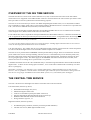
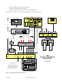
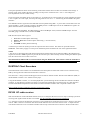
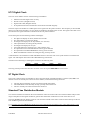
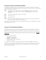
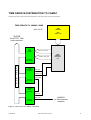
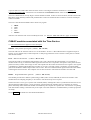
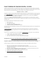
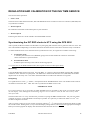
THE ISAAC NEWTON GROUP OF TELESCOPES
THE ING TIME SERVICE
REV 1.0
Author :
Date :
Source :
E. J. Mills (Electronics Group)
July 2002
~eng/document_archive/electronics/time_service/time_service.doc
This document is also available in PDF format in the public_html directory at:
http://www.ing.iac.es/~eng/electronics/misc/time_service.pdf
TABLE OF CONTENTS
OVERVIEW OF THE ING TIME SERVICE....................................................................................................... 2
THE CENTRAL TIME SERVICE ....................................................................................................................... 2
Wharton Time Display Box ............................................................................................................................ 4
MARCONI Digital Counter-Timer ................................................................................................................. 4
ING Time Service Patch Panel ...................................................................................................................... 4
Dual beam digital storage oscilloscope ......................................................................................................... 4
RADIOCODE GPS-8000 Satellite Controlled Clock..................................................................................... 4
1mS/Sec PULSE GENERATOR ................................................................................................................... 5
The SULZER Quartz Oscillator ..................................................................................................................... 5
Linear Phase Recorders ................................................................................................................................ 5
RUSTRAC Chart Recorders .......................................................................................................................... 6
DX300 HF radio receiver .............................................................................................................................. 6
TIME SERVICE FIBRE OPTIC LINKS .............................................................................................................. 7
Site Time Service Fibre Optic Cables............................................................................................................ 7
CTS Fibre Optic Interface Box...................................................................................................................... 7
JKT Time Service Fibre Optic Cables ........................................................................................................... 9
WHT Time Service Fibre Optic Cables.......................................................................................................... 9
WHT TDS....................................................................................................................................................... 9
THE RGO DIGITAL MODULAR CLOCK ........................................................................................................ 10
HCD precision quartz oscillator ................................................................................................................... 10
Sidereal Rate Generator.............................................................................................................................. 10
UTC Digital Clock ........................................................................................................................................ 11
ST Digital Clock ........................................................................................................................................... 11
Standard Time Distribution Module ............................................................................................................. 11
Computer Frequency Distribution Module ................................................................................................... 12
Computer Time Distribution Module ............................................................................................................ 12
POWER SUPPLY............................................................................................................................................ 14
Servicing the ERSKINE battery charger...................................................................................................... 14
TIME SERVICE DISTRIBUTION TO CAMAC ................................................................................................ 15
CAMAC modules associated with the Time Service ................................................................................... 16
FAULT FINDING ON THE RGO DIGITAL CLOCKS ...................................................................................... 17
REGULATION AND CALIBRATION OF THE ING TIME SERVICE ............................................................... 18
Synchronising the INT RGO clocks to UTC using the GPS 8000 ............................................................... 18
Monitoring ...............................................................................................................................................................18
Re-syncing..............................................................................................................................................................18
Re-calibration of an HCD oscillator ............................................................................................................. 19
INT - HCD Oscillator adjustment........................................................................................................................19
WHT or JKT - HCD Oscillator adjustment.........................................................................................................19
Leap Year and Leap Second insertion ........................................................................................................ 21
Pre-setting for a Leap Year ..................................................................................................................................21
Leap Second insertion ..........................................................................................................................................22
APPENDIX ...................................................................................................................................................... 23
Radio Time Services.................................................................................................................................... 23
Synchronising an RGO clock to UTC using the DX300 .............................................................................. 23
Instructions for resetting the time displays .................................................................................................. 25
RGO clocks.............................................................................................................................................................25
AWR control room clocks .....................................................................................................................................25
GLOSSARY..................................................................................................................................................... 26
Figure 1
Figure 2
Figure 3
Figure 4
Figure 5
Figure 6
Figure 7
ING Time Service interconnections .................................................................................................. 3
Fibre optic interface box circuit ......................................................................................................... 8
RGO Digital Modular clock layout ................................................................................................... 10
RGO digital clock block diagram..................................................................................................... 13
Time service to CAMAC connections ............................................................................................. 15
HCD oscillator compensation.......................................................................................................... 20
Time signal measurement............................................................................................................... 24
OVERVIEW OF THE ING TIME SERVICE
The ING Time Service consists of the Central Time Service (CTS) located in the CLIP centre of the INT and the
remote time service equipment in the WHT and JKT. These are connected back to the CTS via fibre optic cables. These
fibre optic links are used for synchronisation and monitoring purposes.
The time service for each telescope consists of an RGO designed digital modular clock (circa 1982) based on CMOS
logic controlled by a highly stable quartz crystal oscillator made by HCD Research Ltd. The time service provides both
UTC (Universal Co-ordinated Time) and LST (Local Sidereal Time).
The time service for the INT is housed within the CTS. The WHT and JKT time services are installed in rack cabinets
in the computer room (WHT) and the CLIP centre (first floor JKT)
Local sidereal time (LST) is required for telescope POINTING and TRACKING. However, it should be noted that only
UTC is supplied to the Telescope Control System (TCS) from the time service. An algorithm within the telescope
control software converts UTC to LST. The LST output from the time service is used to drive the LST time display
wall boxes and thus serves only as a reference.
n.b. Since the time display wall boxes have been replaced with free standing digital UTC/LST clocks in each control
room, the LST output from the RGO clocks is now redundant.
UTC time (hh:mm:ss) , day number and the year (in BCD data format) together with selected UTC related frequencies
are sent from the RGO digital clocks to the TCS DEC ALPHA computers via CAMAC.
The time service is powered from an ERSKINE constant potential battery charger. These are located in the electrical
power intake rooms of each telescope building. The time service is connected directly across the battery bank (28v),
the mains supply being used to float charge the batteries. If the mains charging fails, the batteries will keep the time
service going for approx. 24 hrs. The mains supply for the ERSKINE unit itself comes from the local UPS, so the
chances of a time service failing due to a power break is very remote.
It should be noted that most of the CTS is dedicated solely to the monitoring and calibration when needed of the RGO
digital clocks. As these use free running quartz oscillators, errors in the order of milliseconds can build up over time
due to crystal ageing.
With today’s technology, the ING time service could be updated using a dedicated GPS system at each telescope.
However, due to expenditure cutbacks and the considerable effort needed in software and hardware changes and the
Time Service being deeply embedded into the TCS/CAMAC systems, I very much doubt if this will happen.
THE CENTRAL TIME SERVICE
The CTS is housed in two full height rack cabinets in the INT CLIP centre and contains:
Left hand cabinet (from the top down)
•
•
•
•
•
•
WHARTON time display box (UTC)
MARCONI digital counter-timer
Time service distribution patch panel (BNC connectors)
GOULD ADVANCE dual beam digital storage oscilloscope
RADIOCODE GPS-8000 satellite controlled clock
Storage shelf for log book , etc
Right hand cabinet (from the top down)
•
•
SULZER frequency standard (used only for backup if GPS-8000 fails)
The INT time service (RGO digital modular clock)
John Mills
The ING Time Service
2
•
•
•
Bank of four RGO built Linear Phase Recorders
Bank of three RUSTRAC chart recorders
DX300 HF radio receiver (used only for backup if GPS-8000 fails)
The drawing below shows the interconnections between the various units of the CTS.
INT RGO clock
UTC
ST
19:47:00
08:23:37
297
206
DX300 HF RECEIVER
HCD
oscillator
14.996
SULZER
Frequency Standard
2002
100KHz
sine wave
output
Aerials
100KHz out
To HF radio
BNC connector
RADIOCODE CLOCKS GPS 8000
1pss
out
1mS/Sec out
Sync enable in
100KHz TTL level
Phase reference
19:47:00
297
A1
B
LPR 1
A1
A1
B
B
LPR 2
A2
LPR 3
B
LPR 4
SITE FIBRE OPTIC CABLES
1ms/Sec (or 100KHz)
From
JKT
WHT
1ms/Sec
To clock syncs
JKT
WHT
+28V
TTL
PSU
RUSTRAC
2
INT- UTC
HCD osc. phase
WHT/JKT- UTC
HCD osc. phase
FIBRE OPTIC to TTL
TXR's
+5V
1mS/Sec
PULSE
GENERATOR
GPS
1mS/S
GPS 1Hz
RUSTRAC
1
WHT/JKT
100KHz
HF radio
UTC
1mS/S
SELECT TIME SERVICE
INT
JKT
WHT
Spare
ING
CENTRAL TIME SERVICE
ARRANGEMENT
1.2345
Link to LPR 2 via the WHT or JKT
TIME SERVICE connectors
Used for HCD oscillator recalibration on
remote RGO clock. * A link must be made at
the remote clock by removing the cable
normally used to bring 1pss back to the CTS
and connecting this to the 100KHz output.
A start
COUNTER / TIMER
eJm Jul 02
B stop
DIGITAL STORAGE
OSCILLOSCOPE
A
B
Figure 1 ING Time Service interconnections
John Mills
The ING Time Service
3
Wharton Time Display Box
This is connected to the Standard Time Distribution module (UTC) via a 9 pin connector on the rear of the INT time
service. It uses an IRIG time signal and serves as a facility for testing other time display boxes used around the site.
As these boxes have been replaced with free standing UTC/LST digital clocks in the control rooms, to all intents and
purposes it is redundant.
MARCONI Digital Counter-Timer
This is used for displaying the instantaneous difference in milliseconds between the UTC reference (GPS-8000) and
UTC(M) as measured from an RGO digital clock. The start signal is triggered from the rising edge of the UTC
1mS/Sec reference. The stop signal from the rising edge of the 1mS/Sec pulses from the selected RGO digital clock.
These signals are available from the BNC connectors on the Time Service Patch Panel.
The rate of drift from an RGO digital clock can be followed on a regular basis and when the error exceeds a few
milliseconds, it can be manually re-synchronised to bring it back into step with the GPS 8000 UTC reference.
To improve measurement accuracy, an external clock is used to drive the counter-timer. The 1MHz signal being taken
directly from the INT RGO digital clock.
ING Time Service Patch Panel
This contains a row of BNC connectors allowing the 1mS/Sec pulses to be measured from any time service using the
MARCONI counter or oscilloscope. Not all the BNC connectors are not used. The ones that are being:
GPS 8000
1Hz
1mS/Sec
Raw
Processed
signal
Signal *
100KHz
Phase ref
link to
LPR-2
HF
Signal
from
HF Radio
Reference
UTC
1mS/Sec
from GPS
*
Signals from ING time services
INT
JKT
WHT
1mS/sec
1mS/Sec
1mS/Sec
* Same signal
The UTC reference signal is left permanently connected to the A inputs of the counter and oscilloscope. It is just a
simple matter of moving the BNC ‘T’ connector (going to the B inputs of the counter and oscilloscope) between the
INT, JKT and WHT connectors to measure the time difference.
Dual beam digital storage oscilloscope
This is used in parallel with the MARCONI counter to measure the difference in UTC between the GPS8000 and RGO
clocks. The 1mS/Sec pulse from the GPS-8000 is displayed on one trace with the oscilloscope triggered off the rising
edge of this pulse. The 1mS/Sec signal from an RGO clock is display on the other beam. Due to the slow duration of
the time base, the oscilloscope is best used in storage mode to see the events.
RADIOCODE GPS-8000 Satellite Controlled Clock
This is the heart of the ING Central Time Service and generates the UTC reference which is used to synchronise and
calibrate the RGO digital clocks at each telescope.
The GPS-8000 contains a rubidium oscillator which in conjunction with GPS satellite correction, provides a highly
stable and accurate long term time scale. The accuracy of UTC being in the order of +/- 150nS or better when tracking
at least one satellite. The stability of the rubidium oscillator being better than 5 x 10-12.
John Mills
The ING Time Service
4
A small antenna mounted on the roof of the west side of the INT building receives the satellite signals at 1.023GHz.
However, due to the screening effect of the dome, some satellites above the horizon may not be received. Reception
from only one satellite is sufficient to lock the GPS-8000 to UTC. A visual inspection of the green status LED’s:
Receiving Sat and Valid Time will generally show all is working correctly.
In the rare case if no satellites are seen, the rubidium oscillator acts as a flywheel keeping UTC stable until a satellite is
found. When this happens, corrections are made to the oscillator to compensate for any small changes that may have
occurred in the mean time. These being in the order of < 50nS per hour.
Various menus can be selected using the front panel keypad. Menu 1 is usually selected as this provides the most
useful information, i.e. The time in hh:mm:ss, day of year, etc
The GPS-8000 provides an output pulse of 1 second duration and is used to synchronise the WHT, INT and JKT digital
clocks when needed. The rising edge of this pulse being taken as the UTC reference.
As well as supplying the time reference for UTC, the GPS 8000 also generates a 100KHz (50% duty cycle) phase
reference TTL signal which is required for the Linear Phase Recorders.
Further information on the GPS-8000 can be found in the User's Manual keep in the filing cabinet near the CTS.
1mS/Sec PULSE GENERATOR
It should be noted that the TTL 1pps signal from the GPS-8000 has a 50% duty cycle. To produce the required
1mS/Sec synchronisation pulse, the signal is modified by passing it through a pulse generator which is simply a
monostable (74LS123) circuit. The RC timing values have been selected to produce one second pulses of 1mS
duration, the rising edge defining the start of a second.
This circuit is fitted into a small plastic box attached to the rear of the ING Time Service patch panel and outputs
directly to the GPS 1mS/Sec and 1mS/Sec UTC patch panel BNC connectors as well as driving the fibre optic
transmitters.
The SULZER Quartz Oscillator
Since the introduction of the GPS-8000, the SULZER high stability quartz oscillator no longer supplies the 100KHz
phase reference for the Linear Phase Recorder bank. It is kept as a backup 100KHz frequency reference in case of
failure of the GPS-8000. It is left continually running and connected to Linear phase recorder 4 (input A2-sine) so that
measurements of phase shift errors between itself and GPS can be monitored occasionally.
n.b. If the SULZER is used to re-calibrate drift on the HCD oscillators, the 100KHz output from the GPS 8000
supplying the A1 inputs via a BNC `T' connector on the linear phase recorder bank will first need to be disconnected.
The cable from the SULZER oscillator can then be plugged into the `T' connector. It should be noted that the 100KHz
signal from the SULZER is a SINE wave thus the switches on the LPR's will need to be placed in the `Sine' position for
input A2 selection and the co-axial link cables moved from the A1 inputs across to the A2 inputs.
Historical Note:
This oscillator along with a bank of others was originally used at the RGO (Herstmonceux) for maintaining GMT (now
known as UTC) in the UK until the introduction of Caesium Beam Atomic clocks in the latter part of the 20th century.
Linear Phase Recorders
These are occasionally used to measure the rate of drift over a long period of time of the HCD quartz oscillators within
the RGO digital clocks. The phase reference signal is a 100KHz TTL square wave derived from the GPS-8000 or the
SULZER quartz frequency standard, (but see above).
The 100KHz square wave output from any RGO digital clock can be phase compared against the reference. Any
change in phase i.e. oscillator drift, will show up as a +/- movement of the meter needle over a period of time. A
provision is included for driving an external 0-1mA DC strip chart recorder of resistance up to 500 ohms.
John Mills
The ING Time Service
5
Front panel push buttons allow for the checking of the meter and the chart recorder's zero and full scale settings. A
locking toggle switch enables the chart recording to be kept clear of either the 100 > 0 or 0 > 100 changeover
area if a particular record is under scrutiny.
On the rear panel, three BNC inputs are provided: A1, A2 and B. The A1 and A2 inputs are switch selectable for either
a sine or square wave TTL input, the A2 inputs being used for sine wave. i.e. When using the SULZER as the phase
reference.
The 100KHz reference signal from the GPS 8000 is fed in parallel using BNC `T` pieces and co-axial links to the A1
inputs of LPR’s 1,2 and 3 with the switches in the TTL position. The B input receives the 100KHz TTL signal to be
phase monitored from a selected RGO digital clock.
n.b. To monitor the SULZER, the GPS reference is fed to the B input socket, with the 100KHz output from the
SULZER going to the A2 socket; switched to SINE.
LPR allocation (from left to right) is:
1.
2.
3.
4.
INT HCD oscillator phase monitoring
WHT or JKT HCD oscillator phase monitoring (* see note below)
Spare unit
SULZER oscillator phase monitoring
A small two pin connector (EXT) provides an output for the chart recorder. The LPR's are powered from the
ERSKINE +28V battery supply via a DC power distribution panel mounted in the rear of the right hand cabinet.
NOTE
* The use of a Linear Phase Recorder measuring the HCD oscillator drift rate of either the WHT or JKT digital clock
requires the remote 100KHz signal to be put onto the site fibre optic cable normally used for sending the 1mS/Sec pulse
from the remote time service back to the CTS.
The instantaneous millisecond error measurement using the MARCONI timer/counter cannot be used when a
Linear Phase recorder is measuring HCD oscillator drift from either the WHT or JKT RGO digital clock.
RUSTRAC Chart Recorders
Three RUSTRAC chart recorders are mounted below the linear phase recorder bank. These can be connected to any
LPR by moving the link cables between the EXT connectors.
The chart rate is 1 inch per hour and the paper roll will record one month's of data. The full scale deflection (FSD) of
the RUSTRAC recorder is 0 to 10uS across the paper.
Using the RUSTRAC recorder, a trend is displayed after a period showing the rate and direction of drift of an HCD
oscillator. A well adjusted oscillator will show as a straight line plotted after several days with very little deviation.
Careful and methodical adjustment of the multi-turn dial on the HCD oscillator unit is required to achieve this.
Refer to HCD Oscillator calibration section to see how this is done.
DX300 HF radio receiver
With the introduction of the GPS 8000 satellite clock (circa 1990), the HF receiver serves only as a backup system for
receiving time signals within the short wave bands. See the Appendix section for more information.
n.b. Since the erection of the ING met. mast, there is NO outside aerial connected to this receiver. However, the cable
with its ‘UHF’ connector is still there and can be found under the solar screen near the met. mast. A dipole antenna
with feeder rolled onto a reel is available if needed. This is kept in the Time Service drawer in the INT CLIP centre.
John Mills
The ING Time Service
6
TIME SERVICE FIBRE OPTIC LINKS
To allow remote clock synchronisation to UTC and to monitor the rate of HCD quartz oscillator drift in the WHT and
JKT RGO digital clocks, those time services are linked back to the CTS in the INT clip centre via fibre optic ( FO)
cables. Each cable carries four fibres. One pair is used for the ING Time Service.
n.b. The second pair WAS used for the ING DECNET service. However, since the installation of the 10BaseT
distributed network, new site fibres were laid to accommodate this. The other pair now serve as backup fibres.
The time service FO cables carry the following signals:
WHT
• 1mS/Sec signal from the GPS 8000 to the WHT time service (clock synchronisation)
• 1mS/Sec signal from the WHT time service back to the CTS. ( UTC drift monitoring)
JKT
• 1mS/Sec signal from the GPS 8000 to the JKT time service.
• 1mS/Sec signal from the JKT time service back to the CTS.
(clock synchronisation)
( UTC drift monitoring)
n.b. It should be noted that due to the long cable lengths between buildings, a propagation delay occurs which should
be taken into account if microsecond setting accuracy of UTC for the WHT and JKT times services is required. These
being:
•
•
Delay to WHT = 2.90 uS
Delay to JKT = 0.95 uS
Site Time Service Fibre Optic Cables
Two heavy duty armoured FO cables run from wall mounted termination boxes in the INT clip centre. These drop
down through the main cable duct and pass along cable trays in the Electrical Distribution Room and Services Duct on
the ground floor and leave the west side of the building under a manhole marked RGO inside the solar screen. The two
cables split in a second manhole also marked RGO near the fire escape. One cable runs up the duct beside the steps up
to the JKT. The other cable duct follows the road past the generator house and up to the WHT.
CTS Fibre Optic Interface Box
Standard SMA fibre optic to TTL transmitters and receivers from RS Components are used to interface the 1mS/Sec
signals from the GPS-8000 and the remote time services onto the site FO cables. The left hand rack of the CTS contains
the FO interface box (see Figure 2) One tx/rx pair is used for the WHT fibres, the other pair for the JKT. An extra pair
was reserved for the Carlsberg Meridian telescope , but now serve as spares.
SMA FO patch cables pass under the floor from this box to the wall mounted WHT/JKT FO termination boxes.
Connections to the time service patch panel is made using co-axial cable links with BNC connectors. The FO
transmitters are daisy-chained together with BNC `T' connectors and co-ax cable links. The 1pss signal from the GPS
8000 (after first being converted to a 1mS/Sec pulse by the Pulse Generator) drives the FO transmitters.
A small diecast box mounted nearby contains a voltage regulator and associated circuitry to supply +5 volts for the FO
TXR’s and the Pulse Generator This is derived from the +28 volt supply available from the power distribution box.
John Mills
The ING Time Service
7
CTS FIBRE OPTIC - TTL Tx/Rx interface
0V
eJm Aug 02
+5V
F. O.
BNC
2x 74LS08
+
in
Rx
8
gnd
9
1
in
10
+
out
Tx
gnd
JKT
4
1
6
out
5
+
in
Rx
3
gnd
2
1
in
1
WHT
+
out
Tx
gnd
9
2
8
out
10
+
in
Rx
6
gnd
4
2
in
5
SPARE
+
6x 100nf
Tx
gnd
out
1
2
3
out
2
pin 14 +5V
pin 7
0V
WHT and JKT FO - TTL interface boxes use the same circuit as above, but with one TX/RX pair
WHT / JKT
digital clock
UTC phono
connector
panel
1mS/Sec
Clock Sync in
WHT / JKT
FO -TTL
converter
To site FO
termination box
Figure 2 Fibre optic interface box circuit
John Mills
The ING Time Service
8
JKT Time Service Fibre Optic Cables
The armoured FO cable enters the building on the north side and comes up into the electrical power intake room in the
basement. Due to an error made in cable length calculation (was too short), a FO link was made in the basement using
in-line SMA connectors. These are fitted into a conduit box marked FIBRE OPTICS.
Due to the large diameter of the armoured cable and problems in passing this through the conduit, the cable was
reduced in diameter by removing the outer sheath and the armouring.
The cable continues up to the CLIP centre in a conduit to a wall mounted FO SMA termination box. FO patch cables
from this box pass into the time service/networking rack cabinet and connect into a small box which contains the FO to
TTL transmitter and receiver.
BNC to PHONO link cables carry the signals to and from this box to the CLOCK SYNC IN (UTC) and 1mS/Sec (out)
connectors on the rear panel of the digital clock.
The +5 volt supply for the FO TXR’s comes directly from the JKT digital clock via a miniature 2 pin connector.
WHT Time Service Fibre Optic Cables
The armoured fibre optic cable enters the building on the north side and comes up into the power intake room on the
ground floor. The cable then passes through floor ducts into the aluminisation area and runs up the cable tray to the
ceiling and into the control room. The FO cable continues under the floor tiles behind the blue cabinets, through the
terminal area finally terminating in a box with SMA connectors under the floor in the computer room.
FO patch cables from this box pass under the floor into the rack cabinet containing the Time Service, DEC ALHA
TCS computer and the system CAMAC crate. These connect to a small box mounted at the top of the cabinet which
contains the FO to TTL transmitter and receiver.
BNC to PHONO link cables carry the signals to and from this box to the CLOCK SYNC IN (UTC) and 1mS/Sec (out)
connectors on the rear panel of the digital clock.
The +5 volt supply for the FO TXR’s comes directly from the WHT digital clock via a miniature 2 pin connector.
WHT TDS
Below the RGO digital clock is the TDS crate (Time Distribution System). This was used to generate UTC over the
WHT UTILITY NETWORK to the Dutch (MKII) CCD controllers. As these have now been replaced with SDSU CCD
controllers, this unit is now redundant.
n.b. As it is still uncertain if accurate time is needed for instrument control in the future, it has been left connected.
John Mills
The ING Time Service
9
THE RGO DIGITAL MODULAR CLOCK
The drawing below shows the overall layout of the digital clock.
RGO DIGITAL MODULAR CLOCK
LAYOUT
eJm Jul 02
DIGITAL CLOCK
SIDEREAL RATE GENERATOR
HCD Reseach Ltd
Frequency Standard
HCD 12581
640
+ Fine -
Osc
Supply
Freq
Adj
Coarse
PUL SEC-1
SYNC ENABLE
DIGITAL CLOCK
PUL SEC-1
SYNC ENABLE
1.002737*** MHz
UTC
ST
90 9
10 : 20 : 00
04 : 36 : 57
H1 H0 M1 M0 S1 S0
H1 H0 M1 M0 S1 S0
DAY OF YEAR
DAY
SYNCHRONIZE
195
291
STOP D 2 D 1 D 0
STOP D 2 D 1 D 0
YEAR
2002
COMPUTER
COMPUTER
COMPUTER
COMPUTER
STANDARD
STANDARD
TIME
TIME
TIME
FREQUENCY DISTRIBUTION DISTRIBUTION
DISTRIBUTION DISTRIBUTION DISTRIBUTION DISTRIBUTION
Y1 Y0
ADVANCE
100ms 10ms 1ms 100us 10us
RETARD
5
3 6 5
ADVANCE
RETARD
6 0
36* DAY OF YEAR 23:59**
LEAP YEAR
LEAP SECOND
Figure 3 RGO Digital Modular clock layout
A description of each module follows :
HCD precision quartz oscillator
All clock operations are derived from this unit. The oscillator itself consists of a fifth overtone 5MHz quartz crystal
resonator manufactured by HCD Research Ltd. This is a specially selected HCD 125 unit having an ageing rate of less
than 1 x 10⁻¹⁰ per day after 90 days operation. The oscillator is factory sealed and is mounted on a module also made by
HCD together with circuits providing isolated outputs at 10MHz (sine), 5MHz (sine) and 1MHz (CMOS levels). Power
at +28V is directly connected to the rear of the module via a 9 way `D' type connector.
IMPORTANT : The power to the clock should never be removed else long term stability of the quartz crystal
oscillator will be lost
Sidereal Rate Generator
The SRG module is driven with the 1MHz oscillator signal and generates a pulse train at the rate of 1.002737 * * *
MHz to drive the ST clock module. The three least significant digits are adjustable manually from a thumb wheel
switch mounted on the front panel to accommodate for future changes in the rate of the rotation of the Earth. The
current figure for setting these switches is 909 (2002) Info from : http://tycho.usno.navy.mil/sidereal.html
John Mills
The ING Time Service
10
UTC Digital Clock
The UTC clock module consists of the following sub-modules:
•
•
•
•
Mother board with digital clock circuitry.
Divider circuits (Daughter board).
Signals and Codes (Daughter board).
Front panel board with LCD indicators and controls mounted integrally.
The basic input to the module is a 1MHz square wave signal from the quartz oscillator. This frequency is then divided
down to provide all the frequency services which are needed by the digital clock circuits. The signals and codes circuit
provides the time signals which are available from the rear panel connectors.
On the front panel are the following buttons and displays:
•
•
•
•
•
•
•
•
•
Six digit LCD display for hours, minutes and seconds
Six push buttons to set the time display
Four digit LCD display for the day number (0 to 365/366)
Three push buttons for setting the day number
Four digit LCD display for the year
Two push buttons for setting the year (units and tens only)
Five push buttons for ADVANCING the time by preset amounts
Five push buttons for RETARDING the time by preset amounts
Bank of thumbwheel switches for setting the leap year/leap second
A STOP button is also fitted and a SYNC ENABLE button to allow the clock to be synchronised to an external time
signal. The 1mS/S pulse derived from the GPS-8000 being used for this.
The buttons for advancing or retarding the clock have the following rates:
100mS
10mS
1mS
100uS
10uS
The leap year/leap second switches allow for these events to be preset BEFORE the event occurs.
ST Digital Clock
The (Local) Sidereal Time clock module is driven from the output of the SRG module at 1.002737 (909) MHz. The
internal circuits are basically the same as the UTC module, but with the following omissions:
•
•
•
The four digit LCD display for the year and associated push buttons.
The thumbwheel switch assembly for leap year/leap second selection.
The IC's normally associated with the items list above.
Standard Time Distribution Module
Two of these modules are fitted into the clock mainframe. These are fed from the UTC and ST modules and provide a
range of frequencies and signals suitable for general time distribution within the local area of the time service.
The large WHARTON time display boxes for UTC and LST located in the control rooms of each telescope are driven
from an IRIG signal from these modules.
n.b. In recent years, the WHARTON display have been replaced with free running UTC / LST digital clocks, so the
Standard Time Distribution modules to all intents are redundant.
John Mills
The ING Time Service
11
Computer Frequency Distribution Module
This module supplies frequencies relative to UTC required by the TCS computer and CAMAC. These signals are
available both from the rear panel BNC and PHONO sockets and the three 132w Hughes connectors. The frequencies
available from the Hughes connectors are:
1MHz -
A general purpose clock signal supplied to the CAMAC ED012 Pulse Generator and the LP34
Millisecond Generator modules at ALL telescopes and to the MARCONI servo electronics crate
in the WHT
1KHz -
Was used for JKT photometer timing, but is now redundant.
50Hz -
Not used now by TCS
10Hz -
Not used now by TCS
1mS/Sec - Required by the CAMAC LP34 Millisecond Generator. It is also used as the reference signal from the
time service (RGO clock) that can be monitored at the CTS.
Other frequencies are also available, but only from the rear BNC and phono sockets. The 100KHz signal for oscillator
phase checking being one of these.
Computer Time Distribution Module
These modules supply UTC time which is distributed to the TCS computer (now a DEC ALPHA) via CAMAC in
parallel BCD format. Although there are three of these modules, only one is used. The other two serving as spares.
When the clock was originally designed, the requirement was to supply time to the Instrument Control System (ICS)
which also used CAMAC and to a backup ICS computer/CAMAC system used for engineering testing. This is no
longer the case,
The BCD data from these modules are:
•
•
•
•
•
SECONDS ( in units and 10’s )
MINUTES ( in units and 10’s )
HOURS
( in units and 10’s )
DAY OF YEAR ( in units, 10’s and 100’s )
YEAR ( in units and 10’s )
n.b. The ‘20’ (century) as displayed is generated internally by pre-settable links and is NOT sent to the TCS.
A delayed 1pps is also generated to clock the above information into CAMAC. These signals (along with those from
the Computer Frequency Distribution module) are fed to three 132w Hughes connectors on the rear panel. One
connector for each CTD module.
John Mills
The ING Time Service
12
The drawing below shows the interconnections between the various modules. Detailed circuit diagrams and description
of operation can be found in the INT Technical Documentation manuals: 73 and 74.
RGO DIGITAL MODULAR CLOCK
SIDEREAL
RATE
GENERATOR
1.002737*** MHz
BLOCK DIAGRAM
eJm Jul 02
LST
DIGITAL
CLOCK
MODULE
(LST)
STANDARD
DISTRIBUTION
MODULE
(LST)
PHONO
& BNC
CONNS
9W D
TYPES
UTC
1MHz
Clock
DIGITAL
CLOCK
MODULE
(UTC)
HCD
PRECISION
CRYSTAL
OSCILLATOR
(5 MHz)
STANDARD
DISTRIBUTION
MODULE
(UTC)
COMPUTER
FREQUENCY
DISTRIBUTION
MODULE
PHONO
& BNC
CONNS
9W D
TYPES
REAR PANEL
CONNECTORS
COMPUTER
TIME
DISTRIBUTION
MODULE
132W
HUGHES
SOCKET
COMPUTER
TIME
DISTRIBUTION
MODULE
132W
HUGHES
SOCKET
COMPUTER
TIME
DISTRIBUTION
MODULE
132W
HUGHES
SOCKET
BCD
DATA
BCD
DATA
BCD
DATA
Figure 4 RGO digital clock block diagram
John Mills
The ING Time Service
13
POWER SUPPLY
The RGO digital clocks operate at 28V DC. This supply coming directly from an ERSKINE constant potential battery
charger. These are located in the electrical power intake rooms of each telescope building. The clock is connected
directly across the battery bank. If the mains charging fails, the batteries will keep the clock going for approximately
24 hrs. n.b. Less time for the CTS as the LPR bank and GPS8000 also use this supply.
Servicing the ERSKINE battery charger
The 28V DC power input to the clock is via a 3 pin MIL type connector. There are two of these.
The reason being that when the ERSKINE battery units are serviced, the clock can be maintained by connecting
another 28V DC source to the spare connector BEFORE REMOVING THE NORMAL SUPPLY.
The 28V DC supply connectors are protected by power diodes to prevent voltage back feeding. This allows a backup
PSU to be connected with the normal supply from the ERSKINE still in situ.
A ‘tool box’ containing two 12v dry batteries complete with a flying lead fitted with a time service power connector is
available for this. This is kept in the INT Electronics workshop store. It is important that the battery box is checked
and re-charged before use. For added protection, the battery box should be ‘floated’ across a bench PSU with the
voltage adjusted to provide a trickle charge to the batteries.
IMPORTANT NOTE: If the HCD master oscillator STOPS, it can take up to 90 days to re-achieve stability
John Mills
The ING Time Service
14
TIME SERVICE DISTRIBUTION TO CAMAC
The drawing below shows the interconnections. This is the same for ALL telescopes.
TIME SERVICE To CAMAC LINKS
eJm Jul 02
TIME
SERVICE
RGO
digital clock
To TCS
via HYTEC 1386
crate controller
PR2402
dual
input
register
Input A: hh:mm:ss
Input B: day#, year
address
B 0 C0 N10
C
A
M
A
C
TIME
SERVICE
distribution
box
LP34
millisecond 1MHz input
generator
1mS/Sec input
20Hz Strobe
B
U
S
address
B 0 C0 N11
ED012
Pulse
generator
1MHz input
20Hz output
address
B 0 C0 N8
CAMCLK
to 32bit encoder
modules
Figure 5 Time service to CAMAC connections
John Mills
The ING Time Service
15
A pair of multi-core cables taken from one of the clock’s 132w Hughes connectors terminate in a Time Service
Computer Distribution Box. These boxes are mounted near the SYSTEM CAMAC crates at each telescope.
This box is fitted with two 58 way Hughes sockets labelled A and B. Socket A carries the hours, minutes and seconds
BCD data; socket B the day number and year BCD data. Links are made from these connectors via short twisted pair
cables to CAMAC.
This box is also fitted with LEMO sockets which carry signals:
•
•
•
•
•
1MHz
1KHz
50Hz
10Hz
1mS/Sec
related to UTC from the time service needed by the TCS. n.b. Only the 1MHz and 1mS/Sec (1pps) are used now.
CAMAC modules associated with the Time Service
n.b. The information below applies to ALL telescopes.
PR2402 - Dual parallel input register (Address: B0 C0 N10)
The TCS reads in UTC from the time service via this module. hh:mm:ss data in BCD format is supplied to Input A.
The day of year number and year data to Input B. A delayed 1pps from the clock is used as a strobe pulse to read the
data into this module.
LP34 - Millisecond Generator
(Address: B0 C0 N11)
The TCS also needs to read milliseconds related to UTC. This is done using the LP34 module. It is essentially a
divider/counter. Firstly, it divides the 1MHz signal from the time service to produce 1mS pulses. These pulses are then
passed to a binary counter with a range of 1023. The outputs from the counter are then fed to two registers. One register
is updated every millisecond and therefore provides current time. The other register is strobed by an external 20Hz
pulse from the ED012 module and provides staticised time. The TCS reads the strobed register within the LP34 module
containing the staticised count. The computer now has time accurate to 1mS when the encoders were last read.
ED012 - Programmable Pulse generator
(Address: B0 C0 N8)
This module provides the CAMAC system timing (LAM's) and a clock (CAMCLK) to staticise the encoders. This
module allows the sampling frequency to be chosen to suit the telescope servo response.
The division ratio is set to give a system clock of 20Hz (50mS). Although this clock is synchronised to the time service
(derived from the 1MHz signal), it is not necessarily synchronised to the 1mS/Sec pulse. It could start up with any
phase relationship unless the divider module was enabled by the computer at a specific time. The result of not phasing
time and encoder strobing is that there may be an equal or less than 50mS error of indeterminancy of telescope position
on startup.
See the CAMAC documents for more detailed information.
John Mills
The ING Time Service
16
FAULT FINDING ON THE RGO DIGITAL CLOCKS
The RGO clocks are generally very reliable and only require the occasional push of the SYNC buttons to bring ING
time in step with UTC. The rate of drift is very small, usually less than 1millisecond a month. When the drift is greater
than this value, the clock's master HCD quartz crystal oscillator can be trimmed to correct for this.
IMPORTANT NOTE - SPARES
It should be noted that when the Carlsberg Meridian telescope moved over to a PC based TCS several years ago, there
is now a spare RGO clock kept in the store on the second floor of the INT. However, the clock rack is NOT compatible
with the ING RGO clocks as the rear panel connectors are non standard. Also the modules marked MERIDIAN
SPECIAL are of no use. All other modules are compatible.
There are three Computer Time Distribution modules in each clock mainframe. The old Perkin Elmer TCS/ICS
required two of these modules. Since having moved to different ICS computers, there are now TWO spare modules in
each RGO clock.
The minimum requirement for a functional clock are as follows:
1.
2.
3.
4.
HCD oscillator unit
UTC digital clock module
Computer Frequencies Distribution module
Computer Time Distribution Module (one needed)
The sidereal time from the STmodule is used only to drive the Wharton time display wall boxes, this is unimportant for
telescope operation.
A KNOWN PROBLEM is that the small ceramic plate chip decoupling capacitors can break down and drop the
resistance between the supply and ground rails to a low value. The effect of this is either the circuit fails or the +15
or +5v fuse blows.
If a time service is SHOWING the time, but the computer CANNOT READ IT then suspect one of the following:
•
•
•
A faulty Computer Time Distribution module.
A faulty CAMAC PR2402 parallel input register module
The 5v PSU within the clock or possibly a blown fuse on the rear panel.
If for some reason the spare UTC clock module is faulty, it is possible to replace a UTC module with the ST module in
the adjacent slot. n.b. The TCS requires the YEAR value and the ST module cannot supply this information.
TCS Software support will be needed to modify the program to allow the DEC ALPHA to overcome the problem of not
being able to read in the year value from the Time Service. This has been done in the past and a ‘fix’ is available.
If software support is available; to use an LST module in place of a faulty UTC module, proceed as follows:
•
•
•
•
•
•
Remove the UTC module from it's slot and replace with the ST module.
The power does NOT need to be switched off for module replacement and if done would seriously
degrade the clock's stability.
Set up UTC on the ST module. (Set your wrist watch as accurately as possible from another time service)
Set up the correct DAY NUMBER with the associated buttons
Push the SYNC button on the ST module to synchronise the seconds
Check with you watch that the UTC is still correct
Get the TCS software changed to read the year value.
John Mills
The ING Time Service
17
REGULATION AND CALIBRATION OF THE ING TIME SERVICE
This involves three operations:
1. Once a week
Check the rates of drift between the INT, JKT and WHT RGO clocks in relation to the UTC reference (GPS 8000) and
re-synchronise if needed.
2. When required
Re-calibration of the RGO clocks HCD quartz crystal oscillators.
3. When required
Presetting the clocks for a LEAP YEAR or LEAP SECOND insertion.
Synchronising the INT RGO clocks to UTC using the GPS 8000
After a period, the HCD oscillators will drift due to crystal ageing and will either lose or gain time relative to UTC. The
rates will be different depending on oscillator calibration and characteristics. This factor cannot be easily corrected for.
To enable the RGO clocks to be monitored and re-synchronised to UTC, two signals are available. These being:
1.
To the RGO clocks
A 1mS/Sec pulse from the CTS (GPS8000) going to the CLOCK SYNC IN connectors on the RGO
clocks and used for re-synchronisation.
2.
From the RGO clocks
A 1mS/Sec pulse returning to the CTS for monitoring purposes.
n.b. In the case of the WHT and JKT clocks, these signals are sent over fibre optic cables.
Monitoring
Using the MARCONI counter in the CTS, move the BNC ‘T’ connector between the WHT, INT and JKT 1mS/Sec
connectors on the Time Service patch panel. The difference in milliseconds between UTC (GPS 8000) and an RGO
digital clock can be easily seen. The values obtained should be recorded in the Time Service log book.
Re-syncing
If a significant error exists ( +/- 2mSecs ) then push the SYNC ENABLE button on the UTC module of the clock for
one duration of the PUL SEC-1 LED. This will re-synchronise the RGO clock to UTC.
IMPORTANT NOTE
For reasons unknown, the act of pushing the SYNC ENABLE button on the WHT or JKT clocks can sometimes STOP
the time display. Thus, although the second rising edges are correct relative to UTC, the time can be out by whole
units of seconds.
The bottom line here is to ‘carry’ the time with you when re-syncing the WHT and JKT clocks. Set your wrist watch
(a digital one is best) to the GPS 8000 as accurately as possible. It is quite easy to obtain time better to a 1/10th of a
second on a digital wrist watch.
After re-syncing, if there is an error of units of seconds, push the S0 – S1 buttons below the LCD time display to make
the seconds correct. Pushing these (or any of the time display setting buttons) will fast slew the appropriate LCD digits.
Hold your watch up against the display and check that the time between the two is correct.
John Mills
The ING Time Service
18
Re-calibration of an HCD oscillator
If an RGO clock is losing or gaining time rapidly ( > 1millisecond a week ), this is a sign that the rate of drift of an
HCD oscillator is excessive and needs to be compensated for.
As the GPS8000 uses a very stable RUBIDIUM oscillator which is constantly being corrected by GPS satellite signal
reception, a signal derived from this oscillator can be used as a UTC frequency standard to make phase comparison
checks against the HCD oscillators in the RGO clocks. The Linear Phase Recorder (LPR) bank and RUSTRAC chart
recorders in the CTS are used for this.
The LPR works by comparing the phases between two 100KHz TTL signals and displaying the rate of change on a
meter. Because the rate of change can be very slow, the external output from the LPR is fed to a chart recorder thus
phase changes between the reference oscillator and HCD oscillator under test can be monitored over long periods.
The Linear Phase Recorders are connected in the following way:
•
•
•
•
LPR 1
LPR 2
LPR 3
LPR 4
Constantly monitors the phase between the INT HCD oscillator and the rubidium standard
Can monitor the phase between the WHT (or JKT) HCD oscillators and the rubidium standard
Not used (spare)
Constantly monitors the phase between the SULZER oscillator and the rubidium standard
The RUSTRAC recorders can be connected to any LPR by simply moving the flying lead between them. Generally,
RUSTRAC 1 is connected to LPR 1 (INT) and RUSTRAC 2 to LPR 2 (WHT or JKT) n.b. Although there are three
RUSTRAC recorders, the right hand one has a faulty coil and can’t be used.
Note: The direction of movement of the pen on the chart is dependant on the way the reference and comparison phase
signals are connected to the LPR. The reference phase is taken to the A1 inputs (switched to TTL) of LPR’s 1, 2 and 3
and the HCD oscillator under test taken to the B input (TTL only). A movement of the pen from LEFT TO RIGHT
indicates that an RGO clock is LOSING time relative to UTC.
INT - HCD Oscillator adjustment
•
•
•
•
•
Put a chart paper roll in the left hand RUSTRAC recorder, switch it on and let it run for an hour or so.
Check the slope of the plot.
The ideal response is a line running vertically down the chart constantly, but this is impossible to achieve.
Adjust the dial on the INT HCD oscillator a small amount (e.g. 10 dial units) + or - and check how the slope
of the plot has changed.
IMPORTANT: Record the dial settings as you make the adjustments. You can then interpolate between the
values to reduce the angle of slope.
The shallower the angle of the slope, the faster the rate of phase change is between the oscillators. The direction of the
slope indicates whether the oscillator under test is running FAST or SLOW relative to the UTC rubidium standard.
The full scale deflection of an LPR/RUSTRAC equates to a drift rate of 10uS. See Figure 6 for more information.
WHT or JKT - HCD Oscillator adjustment
The same procedure as above is used, but with one IMPORTANT difference. The 100KHz signal from either the WHT
or JKT time service needs to be sent to the fibre which is normally used for monitoring back at the CTS.
•
•
•
•
•
At the WHT (or JKT) remove the cable with a PHONO plug going to the 1mS/Sec connector (UTC) at the
rear of the clock.
Re-connect this cable to the ‘floating’ PHONO inline socket lead coming from the 100KHz connector.
Back at the CTS, plug in a link cable between the WHT (or JKT) patch panel connector and run this to the
connector marked: WHT / JKT 100KHz phase. This enables the HCD phase to be compared on LPR 2
Put a chart paper roll in the middle RUSTRAC recorder, switch it on and let it run for an hour or so.
Check the slope of the plot after an hour. The rest of the procedure is as for the INT, but necessitating
occasional trips to the WHT or JKT to make HCD oscillator adjustments.
John Mills
The ING Time Service
19
The examples below show the sort of responses which could be obtained after 3 hours of monitoring. n.b. The 500 set
on the dial shows the HCD oscillator FINE adjustment set to mid-range, but in practice this would never be the case.
The chart on the left shows a NEGATIVE rate of oscillator drift of 10uS an hour which if not compensated for would
accumulate to ~ -1.7mS a week. This is severe and the oscillator rate would need increasing to reduce this value.
The example on the right shows a POSITIVE rate of drift in respect to UTC of 10uS in 3 hours (560us a week).
Although not so severe an improvement can be made by decreasing the value shown on the dial.
Only make SMALL adjustments in the beginning (not more than 10 dial units) and recheck the slope of the chart after
an hour. Aim to get the plot on the chart as vertical as possible. If the plot is running off or near to the edge of the
paper, toggle the switch on the LPR to bring the pen back into the middle of the chart.
A time may come when it is NOT possible to adjust the FINE oscillator rate (max. or min. value reached). In this case
it will be necessary to adjust the COARSE control. If this is required, reset the FINE control to mid range (500) and
VERY CAREFULLY move the spindle a quarter turn either CW or CCW and check the slope on the chart. Always
make a note of spindle direction (CW or CCW) and the distance turned; use the screwdriver slot as a guide. When the
plot starts to ‘open up’ again, use the FINE control to refine the correction.
A week of monitoring and HCD oscillator adjustments should be enough time to bring the drift rate of an RGO clock
down to a small value and allow it to run for many months without attention. n.b. It is normal for the HCD oscillators
to ‘walk around’ occasionally with the plot changing direction.
Increase
rate
Decrease
rate
500
500
1
1
2
2
3
3
HCD oscillator rate
losing against UTC
HCD oscillator rate
gaining against UTC
Figure 6 HCD oscillator compensation
John Mills
The ING Time Service
20
When the charts have produced a reasonably ‘straight line’ for a week or so, the chart recorders can be switched off
from their mains sockets at the bottom of the right hand cabinet.
If either the WHT or JKT oscillator was re-calibrated, remember to disconnect the 100KHz link cable and plug the
PHONO lead back into a 1mS/Sec (UTC) to enable weekly checks at the CTS.
Leap Year and Leap Second insertion
Presetting for a Leap Year and Leap Second insertion is controlled by the bank of thumbwheel switches at the bottom
of the UTC clock module.
Note: The RGO clock cannot automatically change for leap year or leap second events. This must be preset BEFORE
the event occurs.
Pre-setting for a Leap Year
A normal year consists of approximately 365.25 days. Due to this accumulation of 4 x 0.25 days, an extra day needs
to be added every four years, a leap year having 366 days. At the time of writing, the next leap year will be 2003.
To preset the clock for a LEAP YEAR, simply change thumbwheel (1) to a 6 n.b. This switch has only two settings
(5 or 6) and must be left on 5 if the year is normal with 365 days.
Normal year (no leap second added)
1
5
Leap
year
THUMBWHEELS
2
3
4
5
6
3
6
5
6
0
Day of year
Leap
number
second
Leap year (no leap second added)
6
Leap
year
3
6
5
Day of year
number
6
0
Leap
second
n.b. The settings for thumbwheel switches 2, 3 and 4 (Day of Year) are NOT important if the Leap Second switches, 5
and 6 are left at 60.
John Mills
The ING Time Service
21
Leap Second insertion
Leap seconds are necessary to keep UT1 within 0.9 seconds of UTC. See the Glossary section for more details.
Notification of a LEAP SECOND insertion is sent to the ING (the software group) in advance from the International
Earth Rotation Service (IERS) in Paris in monthly bulletins. http://maia.usno.navy.mil/
In recent years, a leap second has been inserted at midnight on the 30th June. However, the IERS may decide this needs
to be done on the 31st December. The present trend is that the rate of rotation of the Earth is slowing down in respect to
TAI therefore requiring a POSITIVE leap second to be inserted. At the time of writing (July 2002), NO Leap second
is required.
When a Leap Second notification is sent, it is advisable to preset the thumbwheel switches on the ING digital clocks
in the INT, JKT and WHT well in advance.
Set thumbwheel switches 2, 3 and 4 to the Day of Year number when the Leap Second will be inserted and change the
Leap Second switches to read 61. This will insert one second at 00:00:00 hrs UTC.
IMPORTANT: Once the event has occurred, remember to return the leap second thumbwheel switches back to 60.
Examples:
Leap second to be inserted on the 30th June (normal year)
5
Leap
year
1
8
1
Day of year
number
6
1
Leap
second
Leap second inserted on the 31st December (normal year)
5
Leap
year
3
6
5
Day of year
number
6
1
Leap
second
Leap second inserted on the 30th June (leap year)
6
Leap
year
1
8
2
Day of year
number
6
1
Leap
second
Leap second inserted on the 31st December (leap year)
6
Leap
year
3
6
6
Day of year
number
John Mills
6
1
Leap
second
The ING Time Service
22
APPENDIX
Radio Time Services
In the event of the GPS8000 failing, the DX300 HF receiver in the central time service rack can be used for receiving
time signals transmitted on the short wave bands. The radio time services best received in La Palma are:
•
•
Callsign RWM on 14.996Mhz (Moscow, Russia) mode CW (Note 1)
Travel time from transmitter to La Palma = 18mS
Callsign EBC on 12.008Mhz (Cadiz, Spain) mode AM (Note 2)
Travel time from transmitter to La Palma = 4.5mS
Note 1: This time service is available 24hrs, but second pips are transmitted only between minutes 10 to 30 and 40 to
60 in each hour. The remaining 20 minutes being either silent or just a steady carrier. As the mode of transmission is
CW, the lower right hand control on the DX300 must be set to USB to resolve the pips as audible tones.
Note 2: This time service is only available between 10:00 and 10:25 hours daily. As the travel time is only 4.5mS this
would be a better choice to use as errors in measurement due to signal propagation are minimised. However, there is
often a strong commercial broadcasting station on this frequency which can make good reception and thus
measurement very difficult. As the mode of transmission is AM, the lower right hand control on the DX300 should be
set to that mode.
The travel time for the signals to arrive at La Palma are calculated on a ground wave signal travelling from point to
point along the Earth's surface. In practice, the mode of propagation will be via ionospheric reflection (skywave), but
this would be very difficult to calculate as this varies between day and night and the time of the year. The errors
involved would be in the order of 10's of kilometers. This would add a few microseconds to the ground wave
calculations and are of no significance as the best measurement we can expect from a short wave transmission is to 1 or
2 milliseconds.
Synchronising an RGO clock to UTC using the DX300
The Digital storage oscilloscope in the Central Time Service rack is best used for making these adjustments. To get
reliable triggering on the MARCONI counter-timer is very difficult.
The example given is using the RWM transmission on 14.996MHz as this is available 24 hours albeit that there are
unusable periods within each hour. (see Note 1)
Note : There is no permanent aerial on the roof of the INT connected to the DX300 (since the erection of the Met
frame). If the DX300 is used, it is necessary to connect the dipole antenna (kept in the Time Service filing cabinet in
the CLIP centre). String out the dipole antenna in roughly a NW/SE direction from a suitable point and connect up the
UHF connector on the feeder reel using an in-line UHF barrel connector to the antenna cable (fitted with a UHF
plug). The cable can be found under the solar screen near the Met. frame.
Back at the CTS in the INT CLIP centre, do the following:
•
Connect the A channel of the oscilloscope to the time service to be calibrated e.g. The 1mS/Sec pulses from
the WHT, INT or JKT clock.
•
Connect the B channel of the oscilloscope to the BNC connector labelled HF radio on the patch panel.
•
Tune in the DX300 receiver to the RWM transmission on 14.996MHz. You need to peak up both the preselector and main tuning dials to get the strongest signal. The mode switch needs to be set to USB.
John Mills
The ING Time Service
23
•
Provided you haven’t found a period of silence or just carrier (see Note 1) you will hear either regular second
pips or ‘punctuated’ second pips with some modulation between them. This is un-important, you can use
either signal.
•
With the oscilloscope SYNC set to channel A, the time signal should appear as a burst on channel B with
the 1mS/Sec pulse from the clock occurring at the left-hand edge of channel A.
Time base = 5mS/cm
Ch A
1mS/sec pulse
18mS
Time signal
Ch B
Figure 7 Time signal measurement
In reality, the time signal will not be a clean signal as shown in the diagram, usually it is going up and down as
the signal strength changes or sometimes fading completely into the noise!
•
If UTC(M) (measured) is on top of UTC, this value should be around 18mS RWM (or 4.5mS EBC). If these
values are significantly different then push either the 100’s, 10’s or 1mS ADVANCE or RETARD buttons on
the UTC clock module until the offset shown on the oscilloscope is correct. In practice it is very difficult to
determine the leading edge of the time signal. Just get it as close as possible
•
When using the slewing buttons, hold the button down and wait for the PULSE SEC-1 led to trigger before
releasing. Keeping a button pushed will increment or decrement the time by the preset amount on every
second pulse. Monitoring the PULSE SEC-1 led when operating the slewing buttons will assist with this
operation.
This is somewhat difficult when the WHT or JKT clocks are calibrated against the time signal. In this case, a
second person needs to be at the remote clock making the adjusts and in contact with the person via a
handheld radio or the intercom who can monitor the oscilloscope.
n.b. If the time signal is strong as seen on the oscilloscope, it may be possible to use the timer/counter display
which is connected in parallel also. It should show a reasonably constant value. This may dither somewhat due
to changes in propagation of the time signal or signal strength. What to look for is a trend for the counter timer to show a value of ~18mS (or ~4.5mS with EBC) with regularity.
•
Once the clock is calibrated, ensure that the time is correct with another RGO clock. Pushing the 100mS
slewing buttons can cause the clock gain or lose whole seconds. If this happens, push the S0 – S1 buttons
below the LCD time display to make the seconds correct.
John Mills
The ING Time Service
24
Instructions for resetting the time displays
RGO clocks
If a UTC module has been removed for repair, it will be necessary to reset the LCD displays to the correct time. Start
by first setting your (digital) wrist watch to within 1second of UTC using the time from a working RGO clock or from
the GPS 8000.
Set the time display to the correct time with the associated push buttons in the order:
•
•
•
•
•
•
Tens of HOURS
Units of HOURS
Tens of MINUTES
Units of MINUTES
Tens of SECONDS
Units of SECONDS
The time should then be within a few seconds of UTC. Re-adjust the seconds buttons so that the displayed time is more
or less in synchronism to your watch. When satisfactory, use the procedures as described previously to synchronise the
seconds to UTC.
Set the DAY NUMBER and YEAR displays to their correct values with the appropriate push buttons below those
displays.
Although Sidereal Time from the RGO clocks is not used, to make it correct use the ST value as displayed on the TCS
Info Display window using the procedure above. n.b. The Info Display does not get the instantaneous time due to
delays in the TCS when updating the window, but certainly for setting LST, it is more than adequate.
AWR control room clocks
These clock replacements for the WHARTON display wall boxes were not quite as I intended! We specified time
displays that were driven from the RGO clocks (as per the WHARTON units), but ended up with a free standing
UTC/LST clock driven from an internal (and NOT very precise) crystal oscillator. Looks like we’re stuck with them.
Very pretty, but not that accurate!
To adjust these, you need to hold the SET button whilst operating the FAST (hours) or SLOW (minutes) buttons.
Get UTC time as close as possible within 30 seconds BEFORE the minute event occurs then push the SLOW button to
start the minutes running co-incident with the TCS Info Display. The LST display is set in the same way.
It’s a fiddle-arse task, but once done a few times you’ll get the hang of it ☺
John Mills
The ING Time Service
25
GLOSSARY
Brief explanation of Time Scales
UT Universal Time
This is the mean solar time used for civil timekeeping purposes and is formally defined by a mathematical formula
which relates UT to Greenwich Mean Sidereal Time. This is determined from observations of stars crossing the
meridian.
UT1 Previously known as Greenwich Mean Time (GMT)
Is UT corrected for the effect of small movements of the Earth relative to the axis of rotation (polar variation).
TAI
International Atomic Time
Is the most precisely determined time scale for astronomical use. The scale results from analyses by the Bureau
International des Poids et Mesures in Paris from atomic time standards of many countries. The SI definition of the
second being:
The second is the duration of 9 192 631 770 periods of the radiation corresponding to the transition between two
hyperfine levels of the ground state of the caesium-133 atom
UTC Universal Co-ordinated Time.
Since 1st January 1972, the time scale distributed by most radio time services has been based on redefined co-ordinated
time (UTC) which differs from TAI by an integral number of seconds. UTC is maintained within 0.9sec of UT1 by the
introduction of one second steps (leap seconds) when necessary, normally the last day of June or December at
24:59hrs.
DUT1, an approximation to the difference UT1-UTC, is transmitted in code on the radio time signals.
At the time of writing (July 2002): UTC-TAI = -32 seconds exactly
GMST Greenwich Mean Sidereal time
The interval of time between two consecutive transits of a star crossing the prime meridian of Greenwich 0o longitude.
LST Local Sidereal Time
The interval of time between two consecutive transits of a star crossing the local meridian of observation. Local mean
sidereal time is computed from the current Greenwich Mean Sidereal Time plus an input offset in longitude converted
to a sidereal offset by the ratio 1.00273790935 of the mean solar day to the mean sidereal day.
Sidereal time gains approximately 4 mins daily on UT. This is due to the fact that sidereal time takes into account not
only the 24hr Earth rotational period, but also the rotation of the Earth around the Sun. Hence, the time recorded when
a star crossing the meridian when measured the next night, will be approximately 4 minutes later.
The ING TCS computers calculate the local sidereal time (knowing the UTC and the longitude of the local meridian)
and use this to staticise (read) the position encoders.
John Mills
The ING Time Service
26