1
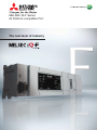
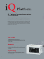
MELSEC iQ-F Series
iQ Platform-compatible PLC
The next level of industry
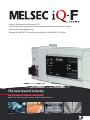
Witness the evolution of the micro PLC.
Designed on the concepts of outstanding performance, superior drive control,
and user centric programming,
Mitsubishi's MELSEC-F Series has been reborn as the MELSEC iQ-F Series.
The next level of industry
From stand alone use to networked system application,
MELSEC iQ-F Series brings your business to the next level of industry.
Conveyance
2
Food & Beverage
Packaging
Air-conditioning
New micro PLC designed on the concepts of ...
Outstanding Performance
- Completely redesigned, high speed
system bus
- Extensive built-in functions
- Enhanced security functions
Superior Drive Control
Intuitive Programming
Environment
- Built-in positioning (4-Axis 200 kHz)
- Easy programming by drag and drop
- Simple linear interpolation
(2-Axis simultaneous start)
- Reduced development time with
module FB
- Synchronous control with Simple Motion
unit (4-Axis)
- Parameterized setup for a variety of
functions
- No need for dedicated positioning
software
The next level of industry
3
iQ Platform for maximum return
on investment
Minimize Total cost, Seamless integration, Maximize productivity, Transparent
communications: these are common items that highlight the benefits of the iQ Platform.
Enhanced further with the arrival of the new MELSEC iQ-F Series Programmable Logic
Controller (PLC), reducing costs and improving productivity can be realized even easier.
The iQ Platform minimizes TCO at all phases of the automation life cycle by improving
development times, enhancing productivity, reducing maintenance costs, and making
information more easily accessible.
PLC & HMI
1. The new MELSEC iQ-F Series system bus is 150-times faster
realizing improved system performance
2. Program standardization through function blocks and
module labels
3. Powerful and robust security features
Network
1. CC-Link IE Field, 1Gbps high-speed and large bandwidth
communications network
2. Seamless connectivity within all levels of manufacturing
with SLMP
Engineering
1. Automatic generation of network configuration diagram
2. Share parameters across multiple engineering software via
MELSOFT Navigator
4
ER
P
ERP (Enterprise resource planning)
MES (Manufacturing execution system)
ME
S
PLC & HMI
Network
Engineering
environment
n
io
at r
m e
to roll
u
A ont
C
Transparent
connectivity
ed
at
r
g k
te wor
n
I et
N
d
te g
a
r n
eg eeri
t
In in
g
En
5
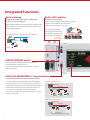
Integrated Functions
Built-in Analog
Built-in SD Card Slot
Integrated 2 ch analog input and 1 ch analog output
(12 bit 0 -10 V DC input/output)
FX5U is equipped with analog control capabilities right out of the
box. No ladder logic is required when using parameter setting in
the programming software.
Standard external memory
External memory is useful for updating PLCs in the field.
Program can be loaded onto SD card and then
transferred to as many PLCs as necessary.
SD card can also be used for
data logging. Record keeping is
›› Example of analog application with 2AD and 1DA.
important for data analysis and
tracking machine performance.
Ethernet
... Future support
FX5U (Master)
GOT
Inverter
RUN/STOP/RESET Switch
The run/stop switch conveniently includes the same reset
functionality found on high end devices.
PLC can be rebooted without turning off the main power for
efficient debugging.
Built-in RS-485(MODBUS®) Communication
No need for additional options for RS-485 communication
For related systems and data transfer with external equipment
and third party devices, serial communication has long been the
established connection method. Serial communication allows the
FX5U to connect both efficiently and reliably with other PLCs,
›› Inverter Communication
FX5U(Master)
RS-485
Max. 50m
Max. 16 inverters
sensors, printers, and modems, etc. Multi-drop networks,
non-protocol communication, and remote maintenance are just
some of the many uses.
Mitsubishi inverters
›› MODBUS Communication
FX5U(Master)
Modbus(RS-485)
Max. 50m
Max. 32 stations
Modbus Equipment
(Inverter, Thermoregulator, and etc.)
6
The next level of industry
Security
High-speed System Bus
MELSEC iQ-F provides advanced security functions (file password,
The MELSEC iQ-F high speed system bus provides seamless data
remote password, security key) for protection against unauthorized
transfer from/to the CPU.
access.
With new architecture that realizes data speeds of 1.5 k words per
×
×
›› Example of Security key function.
Unauthorized
copy
ms (150-times faster than FX3U), fast response is guaranteed even
when using expansion modules.
Copied program
cannot be excuted
because security key
does not match.
High-speed system bus (approx. 150-times faster)
CC-Link IE slave Module
... Future support
SSCNET Ⅲ/H
Built-in Ethernet port
Built-in Ethernet supporting 8 ch
In the information age, Ethernet has become the personal,
›› Socket Communication
commercial and industrial standard for easy and efficient data
Communicate with PLC and other devices.
transfer. Whether it is between multiple PLC systems or PLC and
HUB
PC servers, industrial users dictate foremost that data must always
be consistent even in high-noise environments.
›› MODBUS/TCP client
... Coming Soon
›› Remote Maintenance
Program read/write can be made by
GX Works3 connected via VPN.
PC
VPN router
VPN Tunnel
VPN router
›› SLMP Communication
Device data read-out/writing to a PLC from
an external device is possible.
HUB
Easy parameter setting
PC
7
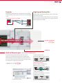
Positioning Solution
Built-in Positioning (4-Axis built-in)
Up to 8 ch 200 kHz
The built-in high-speed pulse inputs and outputs on the FX5U, with special positioning
operations instructions, are designed to satisfy simple independent-axis positioning
applications using servo and stepping motors with speed and precision.
Positioning operations on different axes can also be started simultaneously.
FX5U-32M : 6 ch 200 kHz+2 ch 10 kHz
1st Axis
200 kHz
2nd Axis
200 kHz
3rd Axis
200 kHz
Pulse Output
4th Axis
ON (Forward Rotation)
200 kHz
OFF (Reverse Rotation)
Direction
Simple Linear interpolation (2-Axis simultaneous start)
Y coordinate
Target position(x,y)
y
x X coordinate
Start point
Simple Motion Module (4-Axis module)
Basic Positioning Control
Positioning control is easily executed using a point table.
The machine can coat the workpiece by using a combination of linear interpolation, 2-Axis
circular interpolation, and continuous trajectory control.
A smooth trajectory can be traced with the S-curve acceleration/deceleration function.
3
2
8
1
1. X-Axis
2. Y-Axis
3. Z-Axis
Application examples
• Sealing
• Dispensers
FX5-40SSC-S
Main functions
• Continuous trajectory control
• Linear interpolation
• Circular interpolation
• S-curve acceleration/deceleration
The next level of industry
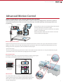
Advanced Motion Control
Making Simple Motion with compactly packed extra functions
Similar to positioning modules, simple motion modules are capable of a wide range of high-precision control such as positional
control, advanced synchronous control, cam control, and speed-torque control with setup being done easily by parameters and
programming.
FX5U
FX5-40SSC-S
• Use synchronous control and cam functionality to make systems
RS-485
that work continuously and maximize output.
Axis1
• In a vertical form, fill & seal machine, perform seal and cut while
the film is continuously fed.
• With 64 cam profiles available, the same machine can be used
P+
Inverter
P+
for many different packaging styles.
P+
MR-JE/J4 series
Axis3
Axis2
Advanced synchronous control
Software-based synchronous control can be used as an alternative to mechanical control, such as gear, shaft, transmission and cam. In
addition, cam control is even easier with cam auto-generation. Synchronous control can be simply operated (start/stop) for each axis,
allowing synchronous and positional control axes within the same program.
• Synchronous control
All axes are synchronized using a synchronous encoder or servo input axes. Up to 4 control axes can be synchronized when using the
synchronous encoder, such as that used for packaging machines, for example.
Cam auto-generation
Cam data for a rotary cutter can be generated automatically simply by registering the
Mark detection
sheet length, synchronization width, rotary cutter axis dimensions, etc.
Cam data
Synchronous
axis length
(circumference)
User-created GOT screen
Sheet
feeding
Synchronization
width
Cam
auto-generation
Sheet length
Cam axis
(synchronized axis)
speed
Sheet feeding
speed
Stroke ratio
Parameter settings,
including items like
sheet length, etc.
Synchronization
width
Mark detection
The actual position of the servo motor can be obtained based on the
registration mark printed on the high-speed moving film. Compensation
of the cutter axis position, based on the registration marks, keeps the
constant cutting position.
9
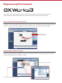
Engineering Environment
GX Works3 consists of various different components that help to simplify project creation and maintenance tasks.
A system design console that enables projects to be created at the system overview stage has been added.
System design with a convenient parts library
Most projects start from system design, so having a software application that caters to this initial stage is important. GX Works3
incorporates a system design feature that enables system components to be assembled directly in the programming software.
It includes a parts library consisting of MELSEC iQ-F Series modules that can be used to simplify system creation.
Simply drag & drop
when adding a module
Drag & Drop
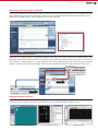
Register module parameters on the fly
Another useful feature is the ability to register parameters automatically. Simply double-click on the desired module and the
corresponding parameters will be registered in the project. A window with an easy-to-use parameter settings screen opens,
enabling module parameters to be modified as needed.
Double click
Module parameter window appears
Parameters automatically added to navigation pane
10
The next level of industry
Main programming languages supported
The main IEC languages are supported by GX Works3. Various different programming languages can be used within the same
project simultaneously and can be viewed easily via the menu tab. The variables and devices used in each program can be
shared across multiple platforms, with user defined function blocks supported.
Structured text
Reduce repetitive program tasks
Global and local variables (labels) are supported providing an easy way to share device names across multiple projects, other
MELSOFT software and third party SCADA. The variables can be registered into either the current program, function block as
a local variable or within the project as a global variable to share across multiple programs within the same project. Variables
specific to a particular module are also available, and can be used immediately, further reducing engineering time and cost.
Global label editor
Drag & Drop
Drag & Drop
Local label editor
Integrated motion setup tool
GX Works3 is equipped with a special motion setup tool that makes it easy to change simple motion module settings such as
module parameters, positioning data and servo parameters. Also, the servo adjustment is simplified using it.
System configuration
Synchronous Control Parameter
Digital oscilloscope
11
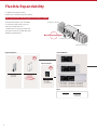
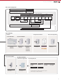
Flexible Expandability
In addition to its built-in features,
FX5U also has a wealth of expansion options.
New communication and analog expansion adapters available!
FX5 Expansion Adapters
The Expansion Adapters, also called ADPs,
are extremely compact and easy to use.
FX5U CPU Module
Various are available for serial
communication and analog. Compared to
the expansion boards, the ADPs offer more
flexibility and performance.
Max. 6 Expansion Adapters
FX5 Expansion Board
FX5 Expansion Modules
Expansion Adapters
FX5U CPU Modules
Max.
Max.
2 ch
4 ch
Expansion Boards
Max.
1 ch
Communication Adapter
FX5-232ADP
FX5-485ADP
Analog Adapter
FX5-4AD-ADP
FX5-4DA-ADP
... Coming Soon
Communication
FX5-232-BD
FX5-485-BD
FX5-422-BD-GOT
FX5U-32MR/ES FX5U-64MR/ES FX5U-80MR/ES
FX5U-32MT/ES FX5U-64MT/ES FX5U-80MT/ES
FX5U-32MT/ESS FX5U-64MT/ESS FX5U-80MT/ESS
Option
12
Battery
SD Card
FX3U-32BL
L1MEM-2GBSD
L1MEM-4GBSD
The next level of industry
Rules of System Configuration
Number of input/output points on whole system
Up to 512 points
1. Number of input/output points
(including input/output occupied points)
Up to 256 points
Up to 16 modules
FX5
Expansion
adapters
(Communication)
CPU module
Up to 2
modules
Up to 1
module
Expansion
board
I/O
module
Intelligent
module
FX3
Extension
power
supply
module
I/O
module
Bus
Intelligent conversion
module
module
Extension
power
supply
module
Up to 1
module
Up to 8 modules
Up to 8
modules
Up to 12 modules
Up to 10 modules
2. Number of remote input/output points for CC-Link
Intelligent Intelligent
module
module
Up to 8 modules
Up to 2 modules
Up to 384 points
CC-Link system
Remote I/O station
Remote I/O station
Remote I/O station
Remote I/O station
Expansion Modules
I/O Modules
Powered I/O Modules
Powered Input/Output Modules
FX5-32ER/ES
FX5-32ET/ES
FX5-32ET/ESS
Bus Conversion Module
Extension Power Supply Module
Intelligent Function Modules
Unpowered I/O Modules
Input Modules
FX5-8EX/ES
FX5-16EX/ES
Output Modules
Simple Motion
Network
FX5-8EYR/ES
FX5-8EYT/ES
FX5-8EYT/ESS
FX5-16EYR/ES
FX5-16EYT/ES
FX5-16EYT/ESS
FX5-40SSC-S
CC-Link/IE Field slave
Power Supply Module
FX5-1PSU-5V
... Future support
FX3U Expansion Modules
Extension Power Supply Module
FX3U Intelligent Modules
Analog
FX3U-4AD
FX3U-4DA
Temperature
FX3U-4LC
Bus Conversion Module
Power Supply Module
FX5-CNV-BUS
FX3U-1PSU-5V
Positioning
FX3U-1PG
Network
FX3U-64CCL
FX3U-32DP
FX3U-16CCL-M
FX3U-64DP-M
High Speed Counter
FX3U-2HC
FX3U intelligent function modules must be set up by PLC program.
Parameter setup is not available in GX Works3.
13
CPU module specification
c
Generic Specifications
c
Item
Operating ambient
temperature[1
0 to 55°C (32 to
Storage ambient temperature
-25 to 75°C(-13 to 167°F )
5 to 95%RH, non-condensation
Storage ambient humidity
5 to 95%RH, non-condensation
Vibration resistance[2
—
Frequency
Acceleration
Half amplitude
Sweep count
Installed on
DIN rail
5 to 8.4 Hz
—
1.75 mm
8.4 to 150 Hz
4.9 m/s
—
5 to 8.4 Hz
—
3.5 mm
8.4 to 150 Hz
9.8 m/s2
—
10 times each in
X, Y, Z directions
(80 min in each
direction)
Direct
installing
2
Specifications
Item
131°F)[2
Operating ambient humidity
Shock resistance[3
147 m/s , Action time: 11 ms, 3 times by half-sine pulse in each direction X, Y, and Z
Noise durability
By noise simulator at noise voltage of 1000 Vp-p,
noise width of 1 μs and period of 30 to 100 Hz
Grounding
Class D grounding (grounding resistance: 100 Ω or less) <Common grounding with a
heavy electrical system is not allowed.>[4
Operating atmosphere
Free from corrosive or flammable gas and excessive conductive dust
FX5U-32M
Rated voltage
100 to 240 V AC
Allowable supply voltage range
85 to 264 V AC
0 to 2000 m
Installation location
Inside a control panel
Overvoltage category
Ⅱ or less
Pollution degree[6
2 or less
Equipment class
Class 2
FX5U-80M
50/60 Hz
Allowable instantaneous power failure time
Operation can be continued upon occurrence of instantaneous
power failure for 10 ms or less.
Power fuse
250 V, 3.15 A
Time-lag fuse
250 V, 5 A Time-lag fuse
Rush current
25 A max. 5 ms or
less/100 V AC
50 A max. 5 ms or
less/200 V AC
30 A max. 5 ms or less/100 V AC
60 A max. 5 ms or less/200 V AC
Power consumption[1
30 W
40 W
45 W
5 V DC power supply capacity
900 mA
1100 mA
1100 mA
24 V DC service power When service power
supply is used for input
supply capacity[2
circuits
When external power
400 mA
600 mA
600 mA
480 mA
740 mA
770 mA
supply is used for input
circuits
[1 : The simultaneous ON ratio of available PLC inputs or outputs changes with respect to the ambient temperature, refer to
manuals of each product.
[2 : For details on Intelligent function modules, refer to manuals of each product.
[3 : The criterion is shown in IEC61131-2.
[4 : Ground the PLC independently or jointly.
[5 : The PLC cannot be used at a pressure higher than the atmospheric pressure to avoid damage.
[6 : This index indicates the degree to which conductive material is generated in the environment in which the equipment is used.
Pollution level 2 is when only non-conductive pollution occurs. Temporary conductivity caused by condensation must be
expected occasionally.
FX5U-64M
Frequency rating
2
Operating altitude[5
c
Power Supply Specifications
Specifications
[1 : This value is for when all 24 V DC service power supplies are used in the maximum configuration in which they can be
connected to the CPU module.
The input current is included.
[2 : When I/O modules are connected, they consume current from the 24 V DC service power.
Performance Specifications
Item
Specifications
Control system
Stored-program repetitive operation
Input/output control system
Programming specifications
Refresh system
(Direct access input/output allowed by specification of direct access input/output [DX, DY])
Programming language
Ladder diagram (LD), structured text (ST)
Programming extension function
Function block (FB), structured ladder, label programming (local/global)
Constant scan
0.2 to 2000 ms (can be set in 0.1 ms increments)
Fixed cycle interrupt
1 to 60000 ms (can be set in 1 ms increments)
Timer performance specifications
100 ms, 10 ms, 1 ms
No. of program executions
32
No. of FB files
16
Operation
specifications
Execution type
Standby type, initial execution type, scan execution type, event execution type
Interrupt type
Internal timer interrupt, interrupt from input, high-speed comparison match interrupt
Command
processing time
LD X0
34 ns
MOV D0 D1
34 ns
Memory capacity
Program capacity
64 K steps (128 Kbytes)
SD memory card
Memory card capacity (SD/SDHC memory card: Max. 4 Gbytes)
Device/label memory
120 Kbytes
Data memory/standard ROM
5 Mbytes
File storage capacity
Device/label memory
1
Data memory
P: No. of program files/FB: No. of FB files
P: 32, FB: 16
Clock function
Display data
Year, month, day, hour, minute, second, day of week (leap year automatic detection)
Precision
-2.96 to +3.74 s (TYP.+1.42 s/d at 0°C (32°F))
-3.18 to +3.74 s (TYP.+1.50 s/d at 25°C (77°F))
-13.20 to +2.12 s (TYP.-3.54 s/d at 55°C (131°F))
(1) No. of input/output points
256 points or less
(2) No. of remote I/O points
384 points or less
Total No. of points of (1) and (2)
512 points or less
Retention method
Large-capacity capacitor
Retention time
10 days
Data retained
Clock data
Flash memory write count
No. of input/
output points
Power failure
retention[1
Maximum 20000 times
[1 : The retention period of a fully charged capacitor (electricity is conducted across the PLC for at least 30 minutes) is 10 days (ambient temperature: 25°C (77°F)).
c
Number of device points
Item
No. of user
device points
Base
Input relay (X)
1024 points
Output relay (Y)
8
1024 points
Internal relay (M)
10
32768 points (can be changed with parameter)[1
Latch relay (L)
10
32768 points (can be changed with parameter)[1
Link relay (B)
16
32768 points (can be changed with parameter)[1
Annunciator (F)
10
32768 points (can be changed with parameter)[1
Link special relay (SB)
16
32768 points (can be changed with parameter)[1
Step relay (S)
10
4096 points (fixed)
The total number of input/output
points must not exceed 256 points.
Timer system
Timer (T)
10
1024 points (can be changed with parameter)[1
Accumulation
timer system
Accumulation
timer (ST)
10
1024 points (can be changed with parameter)[1
Counter
system
Counter (C)
10
1024 points (can be changed with parameter)[1
Long counter (LC)
10
1024 points (can be changed with parameter)[1
10
parameter)[1
Data register (D)
No. of system
device points
Max. number of points
8
8000 points (can be changed with
Link register (W)
16
32768 points (can be changed with
Link special register (SW)
16
32768 points (can be changed with parameter)[1
Special relay (SM)
10
10000 points (fixed)
Special register (SD)
10
12000 points (fixed)
[1 : Can be changed with parameters within the capacity range of the CPU built-in memory.
[2 : Total of the index register (Z) and long index register (LZ) is maximum 24 words.
14
parameter)[1
Item
Base
Module access
device
Intelligent function
module device
10
65536 points (designated by Uc \Gc )
No. of index
register points
Index register(z)[2
10
24 points
Long index register (LZ)[2
10
12 points
No. of file
register points
File register (R)
10
32768 points (can be changed with parameter)[1
No. of nesting
points
Nesting (N)
10
15 points (fixed)
No. of pointer
points
Pointer (P)
10
4096 points
Interrupt pointer (I)
10
178 points (fixed)
Others
Decimal
constant (K)
Signed
—
16 bits: -32768 to 32767,
32 bits: -2147483648 to 2147483647
Unsigned
—
16 bits: 0 to 65535, 32 bits: 0 to 4294967295
Hexadecimal constant (H)
—
16 bits: 0 to FFFF, 32 bits: 0 to FFFFFFFF
Real constant (E)
—
E-3.40282347+38 to E-1.17549435-38, 0,
E1.17549435-38 to E3.40282347+38
—
Shift-JIS code max. 255 single-byte characters
(256 including NULL)
Character string
Single precision
Max. number of points
The next level of industry
Input Specifications
24 V DC input (sink/source)
Output Specifications
Relay output
c
c
Specifications
Item
FX5U-32M
No. of input points
16 points
Connection type
Input type
FX5U-64M
32 points
40 points
Output Specifications
Item
FX5U-80M
FX5U-32M
FX5U-64M
FX5U-80M
No. of output points
16 points
Removable terminal block (M3 screws)
Connection type
Removable terminal block (M3 screws)
Sink/source
Output type
Relay
Input signal voltage
24 V DC +20 %, -15%
External power supply
Input signal current X000 to X017
5.3 mA/24 V DC
30 V DC or less
240 V AC or less ("250 V AC or less" if not a CE, UL, cUL compliant item)
Max. load
2 A/point
The total load current per common terminal should be the following value.
• 4 output points/common terminal: 8 A or less
• 8 output points/common terminal: 8 A or less
Min. load
5 V DC, 2 mA (reference values)
X020 and subsequent 4.0 mA/24 V DC
Input impedance
X000 to X017
4.3 kΩ
X020 and subsequent 5.6 kΩ
ON input sensitivity X000 to X017
3.5 mA or more
current
X20 and subsequent 3.0 mA or more
OFF input sensitivity current
1.5 mA or less
Input response
frequency
X000 to X005
200 kHz
—
X006 to X017
10 kHz
—
X000 to X007
—
200 kHz
X006 to X017
—
10 kHz
X020 and subsequent —
Pulse waveform
Waveform
Open circuit leakage current
—
Response time
OFF→ON
Approx. 10 ms
ON→OFF
Approx. 10 ms
Insulation of circuit
Mechanical insulation
Indication of output operation
LED is lit when output is on
Output circuit configuration
0.1±0.05 kHz
T1
COM
Fuse
T1 (pulse width)
Input response time
(H/W filter delay)
T2
Load
Y
AC power supply
T2 (rise/fall time)
X000 to X005
T1: 2.5 μs or more,
T2: 1.25 μs or more
—
X006 to X017
T1: 50 μs or more,
T2: 25 μs or more
—
A number is entered in the c of [COMc ].
—
T1: 2.5 μs or more,T2: 1.25 μs or more
X010 to X017
—
T1: 50 μs or more,T2: 25 μs or more
X000 to X005
ON: 2.5 μs or less,
OFF: 2.5 μs or less
—
X006 to X017
ON: 30 μs or less,
OFF: 50 μs or less
—
—
ON: 2.5 μs or less,OFF: 2.5 μs or less
—
ON: 30 μs or less,OFF: 50 μs or less
X010 to X017
COM
Fuse
X000 to X007
X000 to X007
40 points
Load
Y
DC power supply
T1
T2
32 points
Transistor output
Output Specifications
Item
FX5U-32M
FX5U-64M
FX5U-80M
No. of output points
16 points
32 points
40 points
Connection type
Removable terminal block (M3 screws)
Output type
Transistor/sink output (FX5U-c MT/ES)
Transistor/source output (FX5U-c MT/ESS)
External power supply
5 to 30 V DC
Max. load
0.5 A/point
The total load current per common terminal should be the following value.
• 4 output points/common terminal: 0.8 A or less
• 8 output points/common terminal: 0.8 A or less
Input response time
(Digital filter setting value)
None, 10 μs, 50 μs, 0.1 ms, 0.2 ms, 0.4 ms, 0.6 ms, 1 ms, 5 ms, 10 ms, 20 ms, 70 ms
When using the product in an environment with much noise, set the digital filter.
Input signal format
No-voltage contact input
Sink: NPN open collector transistor
Source: PNP open collector transistor
Open circuit leakage current
0.1 mA or less/30 V DC
Input circuit configuration
• When using service power supply
Sink input wiring
Voltage drop
when ON
Y000 to Y003
1.0 V or less
Y004 and subsequent
1.5 V or less
Fuse
Response
time
Y000 to Y003
2.5 μs or less/10 mA or more (5 to 24 V DC)
Y004 and subsequent
0.2 ms or less/200 mA or more (24 V DC)
100 to 240 V AC
L
Source input wiring
Fuse
L
N
N
24V
100 to 240 V AC
S/S
Input impedance
Insulation of circuit
Photo-coupler insulation
0V
Indication of output operation
LED is lit when output is on
S/S
Output circuit configuration
Sink output wiring
24V
0V
X
Load
Y
DC power supply
• When using external power supply
Sink input wiring
Source input wiring
Fuse
L
Fuse
L
N
24V
Input impedance
24V
0V
0V
S/S
S/S
X
Input impedance
X
A number is entered in the c of [COMc ]. A number is entered in the c of [+Vc ].
Analog output
Item
Specifications
Specifications
1 points (1 channels)
2 points (2 channels)
Unsigned 12-bit binary
Analog output
Voltage
I/O characteristics,
Maximum resolution
Digital input value
0 to 4000
Maximum resolution
2.5 mV
Voltage
0 to 10 V DC (input resistance 115.7 kΩ)
I/O characteristics,
Maximum resolution
Digital output value
0 to 4000
Maximum resolution
2.5 mV
Accuracy
(Accuracy in respect to
maximum analog
output value)
Accuracy
(Accuracy in respect to
maximum digitaloutput value)
Ambient temperature
25±5°C (77±41°F)
Within ±0.5% (±20 digit[1)
Conversion speed
Ambient temperature
0 to 55°C (32 to 131°F)
Within ±1.0% (±40 digit[1)
Unsigned 12-bit binary
Conversion speed
30 μs/channel (data refreshed every operation cycle)
Absolute maximum input
-0.5 V, +15 V
Insulation method
+V
100 to 240 V AC
Digital input
Item
Digital output
Fuse
N
100 to 240 V AC
Analog input
Analog input
Load
Y
DC power supply
COM
Fuse
Analog output points
Analog input points
Source output wiring
X
Input impedance
Between input terminal and PLC
Not insulated
Between input terminals
Not insulated
Ambient temperature
25±5°C (77±41°F)
Within ±0.5% (±20 digit[1)
Ambient temperature
0 to 55°C (32 to 131°F)
Within ±1.0% (±40 digit[1)
30 μs (data refreshed every operation cycle)
Insulation method
Between output
terminal and PLC
Not insulated
Occupied points
0 points (does not pertain to the max. No. of input/output
points of the PLC.)
Terminal block used
European-type terminal block
[1 : "Digit" refers to digital values.
Occupied points
0 points (does not pertain to the max. No. of input/output
points of the PLC.)
Terminal block used
European-type terminal block
[1 : "Digit" refers to digital values.
Built-in RS-485 communication
Item
0 to 10 V DC (external load resistance 2 k to 1 MΩ)
Specifications
Built-in Ethernet communication
Item
Specifications
Data transmission speed
100M/10M (bps)
Communication mode
Full duplex (FDX) / half duplex (HDX)
Transmission method
Base band
Maximum segment length
100 m (328' 1")
10BASE-T
Cascade connection max. 4 stages[1
100BASE-TX
Cascade connection max. 2 stages[1
Transmission standards
Conforms to RS-485/RS-422 specifications
Cascade
connection
Data transmission speed
Max. 115.2 kbps
Communication method
Full duplex (FDX) / half duplex (HDX)
Protocol type
Maximum total extension distance
50 m (164' 0")
Protocol type
MELSOFT connection
MELSOFT connection
SLMP (3E frame)
Socket communication
Non-protocol communication
Number of simultaneously open connections
allowed
8 connections
MODBUS RTU
Insulation method
Pulse transformer insulation
Inverter communication
Interface
Insulation method
Not insulated
Terminal resistors
Built-in (OPEN/110 Ω/330 Ω)
Terminal block used
European-type terminal block
Cable
used[2
RJ45 connector
For 10BASE-T connection
Ethernet standard-compatible cable, category 3 or higher (STP cable)
For 100BASE-TX connection Ethernet standard-compatible cable, category 5 or higher (STP cable)
[1
: Number of stages that can be connected when a repeater hub is used. When a switching hub is used, check the specifications
of the switching hub used.
[2 : A straight cable can be used. If a personal computer and CPU module are directly connected (simple connection), a cross cable
can be used.
15
Simple motion module specification
c
Control specification
c
Item
Specifications
FX5-40SSC-S
Number of control axes
(Virtual servo amplifier axis included)
Up to 4 axes
Operation cycle (Operation cycle settings)
1.777 ms
Interpolation function
Linear interpolation (Up to 4 axes),
Circular interpolation (2 axes)
Control modes
PTP (Point To Point) control, Trajectory control (both linear
and arc), Speed control,Speed-position switching control,
Position-speed switching control, Speed-torque control
Acceleration/deceleration process
Trapezoidal acceleration/deceleration,
S-curve acceleration/deceleration
Compensation function
Backlash compensation, Electronic gear, Near pass function
Synchronous control
Cam control
Maximum distance between stations [m(ft.)]
100 (328.08)
Peripheral I/F
Via CPU module (Ethernet, RS-485)
Manual pulse generator operation function
Possible to connect 1 module
Synchronous encoder operation function
Possible to connect 4 modules
(Total of the internal interface , via PLC CPU
interface, and servo amplifier interface)
Input signals(DI)
4 points
Number of input points
Input method
Positive common/Negative common shared
(Photocoupler isolation)
Rated input voltage/current
24 V DC/ Approx. 5 mA
Operating voltage range
19.2 to 26.4 V DC
(24 V DC +10%/-20%, ripple ratio 5% or less)
Cam axis (Up to 4 axes)
Number of registration
Up to 64 (depending on memory capacity, cam resolution
and number of coordinates)
ON voltage/current
17.5 V DC or more/ 3.5 mA or more
OFF voltage/current
7 V DC or less/ 1.0 mA or less
Cam data type
Stroke ratio data type, Coordinate data type
Input resistance
Cam auto-generation
Cam auto-generation for rotary cutter
Response time
1 ms or less (OFF→ON, ON→OFF)
mm, inch, degree, pulse
Recommended wire size
AWG24 (0.2 mm2)
Number of input points
1 point
Input method
Positive common/Negative common shared
(Photocoupler isolation)
600 data (positioning data No. 1 to 600)/axis (Can be set
with MELSOFT GX Works3 or a sequence program.)
Parameters, positioning data, and block start data can be
saved on flash ROM (battery-less backup)
Forced stop input signal (EMI)
Approx. 6.8 kΩ
Rated input voltage/current
24 V DC/ Approx. 5 mA
Home position return
method
Proximity dog method, Count method 1, Count method 2,
Data set method, Scale home position signal detection method
Operating voltage range
19.2 to 26.4 V DC
(24 V DC +10%/-20%, ripple ratio 5% or less)
Fast home position return
control
Provided
ON voltage/current
17.5 V DC or more/ 3.5 mA or more
Sub functions
Home position return retry, Home position shift
OFF voltage/current
7 V DC or less/ 1.0 mA or less
Linear control
1-axis linear control, 2-axis linear interpolation control,
3-axis linear interpolation control, 4-axis linear interpolation
control [1 (Composite speed, Reference axis speed)
Input resistance
Approx. 6.8 kΩ
Fixed-pitch feed control
1-axis fixed-pitch feed, 2-axis fixed-pitch feed,
3-axis fixed-pitch feed, 4-axis fixed-pitch feed
2-axis circular interpolation Sub point designation, center point designation
Speed control
1-axis speed control, 2-axis speed control,
3-axis speed control, 4-axis speed control
Speed-position switching
control
INC mode, ABS mode
Position-speed switching
control
INC mode
Current value change
Positioning data, Start No. for a current value changing
NOP instruction
Provided
JUMP instruction
Unconditional JUMP, Conditional JUMP
LOOP, LEND
Provided
High-level positioning
control
Block start, Condition start, Wait start, Simultaneous start,
Repeated start
JOG operation
Provided
Response time
4 ms or less (OFF→ON, ON→OFF)
Recommended wire size
AWG24 (0.2 mm2)
Signal input form
Manual pulse
generator/Incremental
synchronous encoder
signal
Phase A/Phase B (magnification by 4/
magnification by 2/magnification by 1),
PULSE/SIGN
Differential
output type
(26LS31 or
equivalent)
Input pulse frequency
Up to 1 Mpulse/s (After magnification by 4,
up to 4 Mpulse/s)
Pulse width
1 μs or more
Leading edge/trailing edge
time
0.25 μs or less
Phase difference
0.25 μs or more
Rated input voltage
5.5 V DC or less
High voltage
2.0 to 5.25 V DC
Low voltage
0 to 0.8 V DC
Differential voltage
±0.2V
Cable length
Up to 30 m (98.43ft.)
Voltageoutput/ Input pulse frequency
Opencollector
type (5 V DC) Pulse width
Up to 200 kpulse/s (After magnification by 4,
up to 800 kpulse/s)
5 μs or more
Inching operation
Provided
Manual pulse generator
Possible to connect 1 module (Incremental),
Unit magnification (1 to 10000 times)
Leading edge/trailing edge
time
Speed-torque control
Speed control without positioning loops, Torque control,
Tightening & press-fit control
Phase difference
1.2 μs or more
Rated input voltage
5.5 V DC or less
Absolute position system
Made compatible by setting a battery to servo amplifier
High voltage
3.0 to 5.25 V DC/2 mA or less
Synchronous encoder
interface
Up to 4 channels (Total of the internal interface,
via PLC CPU interface, and servo amplifier interface)
Low voltage
0 to 1.0 V DC/5 mA or more
Cable length
Up to 10m (32.81ft.)
Expansion control
Functions that limit control
Functions that change
control details
Other functions
Internal interface
1 channel (Incremental)
Speed limit function
Speed limit value, JOG speed limit value
Torque limit function
Torque limit value_same setting,
torque limit value_individual setting
Forced stop
Valid/Invalid setting
Software stroke limit
function
Movable range check with current feed value,
movable range check with machine feed value
Hardware stroke limit
function
Provided
Speed change function
Provided
Override function
1 to 300 [%]
Acceleration/deceleration
time change function
Provided
Torque change function
Provided
Target position change
function
Target position address and speed are changeable
M-code output function
Provided
Step function
Deceleration unit step, Data No. unit step
Skip function
Via PLC CPU, Via external command signal
Teaching function
Provided
Parameter initialization function
Provided
External input signal setting function
Via internal interface, CPU, servo amplifier
Amplifier-less operation function
Provided
Mark detection function
Regular mode, Specified Number of Detections mode,
Ring Buffer mode
Mark detection signal
Up to 4 points
Mark detection setting
4 settings
Optional data monitor function
4 points/axis
Driver communication function
Provided
SSCNET connect/disconnect function
Provided
Digital oscilloscope
function[2
Bit data
16 ch
Word data
16 ch
[1 : 4-axis linear interpolation control is enabled only at the reference axis speed.
[2 : 8 ch word data and 8CH bit data can be displayed in real time.
16
400 (1312.32)
Servo input axis,Virtual servo amplifier axis,
Synchronous encoder axis
Backup
Manual control
Specifications
SSCNET Ⅲ/H
Maximum overall cable distance [m(ft.)]
Output axis
Number of positioning data
Positioning control
Item
Servo amplifier connection method
Input axis
Control unit
Home position return
Module specification
1.2 μs or less
24 V DC internal current consumption
0.25 A
Mass
0.30 kg
Exterior dimensions [mm(inch)]
90.0(3.55)(H)×50.0(1.97)(W)×83.0(3.27)(D)
The next level of industry
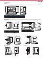
External Dimensions
Main Modules
Unit: mm (inches)
90 (3.55")
80 (3.15")
(Mounting hole pitch)
2-φ4.5 mounting holes(FX5U-32M)
4-φ4.5 mounting holes(FX5U-64M, FX5U-80M)
8 (0.32")
W1
220
(0.873")
83 (3.27")
W
Model
W: mm (inches)
W1 (mounting hole pitch):
mm (inches)
Mass (weight)
FX5U-32Mc
150 (5.91")
123 (4.85")
Approx. 0.65 kg (1.43" lbs)
FX5U-64Mc
220 (8.67")
193 (7.60")
Approx. 1.00 kg (2.2" lbs)
FX5U-80Mc
285 (11.23")
258 (10.16")
Approx. 1.20 kg (2.64" lbs)
• Exterior color : Main body: Munsell 0.6B7.6/0.2
• Accessories : Dust proof protection sheet, Manual supplied with product
Expansion Modules
I/O Modules
Unit: mm (inches)
80 (3.15")
(Mounting hole pitch)
40 (1.58")
140(5.52")(Mounting hole pitch)
83 (3.27")
Model
8 (0.32")
83 (3.27")
150(5.91")
Mass (weight)
FX5-8EX/ES, FX5-8EYR/ES, FX5-8EYT/ES, FX5-8EYT/ESS
90 (3.55")
2-φ4.5 Mounting hole
8 (0.32")
90 (3.55")
80 (3.15")
(Mounting hole pitch)
2-φ4.5 Mounting hole
Approx. 0.2 kg (0.44" lbs)
Model
Mass (weight)
FX5-32ER/ES, FX5-32ET/ES, FX5-32ET/ESS
Approx. 0.65 kg (1.43" lbs)
FX5-16EX/ES, FX5-16EYR/ES, FX5-16EYT/ES, FX5-16EYT/ESS Approx. 0.25 kg (0.551" lbs)
Intelligent Function Module
Extension Power Supply Module
FX5-40SSC-S
FX5-1PSU-5V
80 (3.15")(Mounting hole pitch)
90 (3.55")
80 (3.15")
(Mounting hole pitch)
16 (0.63")
8 (0.32")
50 (1.97")
90 (3.55")
2-φ4.5 Mounting hole
2-φ4.5 Mounting hole
16
(0.63")
8 (0.32")
83 (3.27")
50 (1.97")
83 (3.27")
Expansion Adapters
Bus Conversion Module
FX5-232ADP / FX5-485ADP
FX5-CNV-BUS
8 (0.32") 74 (2.92")
FX5-232ADP
8.8(0.35")
FX5-485ADP
15.1(0.6")
15.1
(0.6")
17.6
(0.7")
8 (0.32”)
90 (3.55”)
80 (3.15”) Mounting hole pitch
90 (3.55")
98 (3.86")
(Mounting hole pitch)
106 (4.18")
2-φ4.5 Mounting hole
8 (0.32”)
16
(0.63”)
83 (3.27”)
17
Products list
CPU & I/O module
Specification
Model
FX5U-32MR/ES
Power Supply
100 to 240 V AC
50/60 Hz
FX5U-32MT/ES
Input
16 points
Output
24 V DC
Sink/source
16 points
Relay
Transistor/sink
FX5U-32MT/ESS
Transistor/source
FX5U-64MR/ES
32 points
32 points
FX5U-64MT/ES
Relay
Transistor/sink
FX5U-64MT/ESS
Transistor/source
FX5U-80MR/ES
40 points
40 points
FX5U-80MT/ES
Relay
Transistor/sink
FX5U-80MT/ESS
Transistor/source
FX5-8EX/ES
Power supply from CPU module
8 points
FX5-16EX/ES
16 points
24 V DC
Sink/source
FX5-8EYR/ES
—
—
—
—
8 points
Relay
FX5-8EYT/ES
Transistor/sink
FX5-8EYT/ESS
Transistor/source
FX5-16EYR/ES
—
—
16 points
FX5-16EYT/ES
Relay
Transistor/sink
FX5-16EYT/ESS
Transistor/source
FX5-32ER/ES
100 to 240 V AC
50/60 Hz
FX5-32ET/ES
16 points
24 V DC
Sink/source
16 points
Relay
Transistor/sink
FX5-32ET/ESS
Transistor/source
Expansion modules
Model
Specification
FX5-40SSC-S
Simple motion module
FX5-1PSU-5V
Extension power supply module
FX5-CNV-BUS
Bus conversion module
Expansion Boards & Adapters
Model
Specification
FX5-232-BD
For RS-232C communication
FX5-485-BD
For RS-485 communication
FX5-422-BD-GOT
For GOT RS-422 communication
FX5-232ADP
For RS-232C communication
FX5-485ADP
For RS-485 communication
Option
Model
FX3U-32BL
Specification
Option battery
User's manuals for the applicable modules
Manual name <manual number>
18
Description
MELSEC iQ-F series FX5U Hardware Manual
<JY997D53401>
Describes the details of input/output specifications, wiring and installation of the FX5U CPU module from FX5U User's Manual [Hardware].
MELSEC iQ-F series FX5U User's Manual
[Hardware]<JY997D55301>
Describes the details on hardware of the FX5U series CPU module, including input/output specifications, wiring, installation, and maintenance.
MELSEC iQ-F series FX5 User's Manual
[Application]<JY997D55401>
Describes basic knowledge required for program design, functions of the CPU module, devices/labels, and parameters.
MELSEC iQ-F series FX5 Programming Manual
[Program Design]<JY997D55701>
Describes specifications of ladders, ST, and other programs and of labels.
MELSEC iQ-F series FX5 Programming Manual
[Instructions, Functions]<JY997D55801>
Describes specifications of instructions and functions that can be used in programs.
MELSEC iQ-F series FX5 User's Manual
[Serial Communication]<JY997D55901>
Describes inverter communication, and non-protocol communication.
MELSEC iQ-F series FX5 User's Manual
[MODBUS Communication]<JY997D56101>
Describes MODBUS serial communication.
MELSEC iQ-F series FX5 User's Manual
[Ethernet Communication]<JY997D56201>
Describes the functions of the built-in Ethernet port communication function.
MELSEC iQ-F series FX5 User's Manual
[Positioning Control]<JY997D56301>
Describes the built-in positioning function.
FX5 Series User's Manual
[Startup]<JY997D55301>
Performance specifications, procedures before operation, and troubleshooting of the CPU module.
The next level of industry
About this product catalog
Due to the constantly growing product range and new or changed product
features, the information in this catalog may be updated without notice.
Please contact your Mitsubishi Electric product provider for more details.
Texts, figures and diagrams shown in this product catalog are intended
exclusively for explanation and assistance in planning and ordering the
FX5 programmable logic controllers (PLCs) and the associated accessories.
Only the manuals supplied with the units are relevant for installation,
commissioning and handling of the units and the accessories. The
information given in the manuals must be read before installation and
commissioning of the units or software.
If any questions arise regarding the application or use of the PLC units and
accessories described in this catalog, please contact your Mitsubishi Electric
product provider.
hEthernet is a trademark of Xerox Corporation.
hMODBUS is a registered trademark of Schneider Electric SA.
hAll other company names and product names used in this document are
trademarks or registered trademarks of their respective companies.
This catalog confers no industrial property rights or any rights of any other
kind, nor does it confer any patent licenses. Mitsubishi Electric Corporation
cannot be held responsible for any problems involving industrial property
rights which may occur as a result of using the contents noted in this
catalog.
©2014 MITSUBISHI ELECTRIC CORPORATION
19
PROGRAMMABLE CONTROLLERS
HEAD OFFICE: TOKYO BLDG., 2-7-3, MARUNOUCHI, CHIYODA-KU, TOKYO 100-8310, JAPAN
http://Global.MitsubishiElectric.com
HIME-L081-A1411(MEE)
New publication, effective Nov. 2014
Specifications subject to change without notice.


![MELSEC iQ-F FX5U Series User`s Manual [Hardware]](http://vs1.manualzilla.com/store/data/005848866_1-47292304553905fa63d352e8811bb59a-150x150.png)