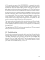
1
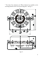
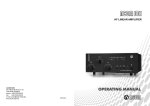
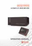
Contents 1. GENERAL INFORMATION 3 1-2. Owner Assistance 3 1-3. Equipment Supplied and Options 3 1-4. Features 3 1-5. Safety Considerations, Explicit Definitions 4 2. INSTALLATION 6 2-1. Unpacking and Initial Inspection 6 2-2. Place selection and mechanical mount 6 2-3. Connections 8 3. OPERATION 10 3-1. OPERATION IN THE ACOM SYSTEM 10 3-2. USER SYSTEMS OPERATION 11 4. MAINTENANCE 11 4-1. The ACOM2000SW Schematic Diagram 11 4-2. Troubleshooting 13 1 5. SPECIFICATIONS 14 5-1. Parameters 14 5-2. Functions 15 5-3. Storage and Shipment 15 2 1. GENERAL INFORMATION 1-1. Introduction and Description This manual explains the installation, operation and maintenance of the ACOM2000SW remote 10 way antenna switch. The ACOM2000SW is a remote 1 out of 10 antennas switch especially designed for use with the ACOM2000S automatic antenna selector and the ACOM2000A automatic HF linear amplifier. Nevertheless, the ACOM2000SW can be easily integrated in other automatic antenna systems or manually controlled, too. 1-2. Owner Assistance If assistance is needed, you should contact your local dealer first. If you still have an issue, you need to discuss with one of ACOMs specialists. The contact information is as follows: fax (+359 2) 920 96 56, e-mail [email protected], [email protected] or by mail: blvd.Nikola Mushanov 151, 1330 Sofia, Bulgaria. 1-3. Equipment Supplied and Options The ACOM2000SW remote antenna switch plus a mating cable connector for input control and power supply, 11 plastic protective caps, and this manual are shipped in one cardboard carton. The automatic antenna selector ACOM2000S is a separably purchasable option. If you have purchased it, the same carton will contain both units. 1-4. Features * One out of 10 antennas, 50 Ohm, up to 60MHz frequency range. * Up to 5kW continuous carrier: Teflon (PTFE) insulated connectors for 100% duty cycle (continuous) operation. * Gold plated and bifurcated contacts for excellent reception, no contact derived cross - modulation phenomenon. 3 * Flat coaxial line construction for excellent VSWR and crosstalk isolation. * Anti - hot switching self protection for reliable contact operation; monitors RF incoming power and generates a ready to transmit output signal for maximum operating flexibility. * Only 0.15 seconds operating time. * Control and power supply mate to the ACOM2000S automatic antenna selector which is directly compatible with the ACOM2000A automatic HF linear amplifier. * Compatible with other automatic systems thanks to the simple 4 - bit BCD control code (positive or inverted, internally selectable). * For manual control, only a simple BCD - coding switch plus 27VDC/150mA unregulated power supply are enough. * Grounds unused antennas during operation for excellent crosstalk isolation; after switching off, all antennas are automatically grounded for maximum lightning safety. * Easy to install: only 2 holes needed, mounting bracket included. * Dust and rain protected (IP53), -30 to +60degs.C operating. 1-5. Safety Considerations, Explicit Definitions The ACOM2000SW remote antenna switch is designed to meet international safety standards. It is powered with safe voltage (27VDC) but it must always be connected to a proper lightni ng protection grounding system for safe operation. This operating manual contains information, precautions, indications for cautions and warnings which must be followed by the user to ensure safe operation and to keep the ACOM2000SW in safe operating condition. PRECAUTIONS: The EXPLICIT DEFINITIONS described below apply to this operating 4 manual: W A R N I N G notes call attention to a procedure which, if not correctly performed, could result in personal injury, fire hazard or electric shock. C A U T I O N notes call attention to a procedure which, if not correctly performed, could result in equipment damage, not only in the switch. N O T E notes call attention to a procedure which, if not correctly performed, could result in inconvenience only. W A R N I N G HIGH VOLTAGE! NEVER use the antenna switch if not connected to a proper lightning protection grounding system. NEVER TOUCH AN ANTENNA during transmission - this may result in an electric shock or burn. WARNING Do not undertake on your own repairs or changes in the construction of the antenna switch in order not to endanger your or others health and life and not to damage the antenna switch and the equipment connected with it, not covered by warranty. The manufacturer is not liable for anothers actions and responsibility shall be assumed by the doer. CAUTION To avoid damage (not covered under warranty) read the Installation - S.2 of this operating manual carefully. If you have any doubts about the installation, operation or safety of the antenna switch, please consult your dealer. 5 2. INSTALLATION 2-1. Unpacking and Initial Inspection NOTE Before you start any action on installing the antenna switch, thoroughly read through this manual. First carefully inspect the cardboard carton and its contents for physical damage. If damage is noticed, notify your dealer immediately. Delay may infringe carriers warranty conditions. Keep all packing for possible future transportation! Check carefully the serial number of the antenna switch with the Table of Individual Data (Table 2-1). If you find any discrepancies notify your dealer immediately to have your warranty information corrected. Serial Number: ................... positive inverted BCD code: Table 2-1. Individual Data 2-2. Place selection and mechanical mount When selecting the mounting place have in mind the following considerations: * Keep the grounding length as short as practical. * Minimize the coaxial cable length. Normally a place near the antennas area (a bit longer common and control cables) would save length from multiple antenna cables. * Keep the highest frequency cables as short as possible even if for the lower frequencies the cables become longer. * The antenna switch design is suitable for outdoor mounting. Nevertheless, if you select (or make especially for it) a shady and dry place, the antenna selector materials would age slowly, i.e. last longer. 6 * Two holes, 9mm diameter and 120mm distanced are available on the mounting bracket to firm it to the mounting base - see Fig 2-1. # $ " % Made in Bulgaria COMMON ! & OT C RE H S/N M SW E AN T E N NA IT ' Fig. 2-1 7 * The principal operating position of the antenna selector is with the cover up (connectors pointing down), but when it is indoor used any position is OK. 2-3. Connections Connections must be accomplished in the order described below, before you apply power supply or control to the antenna switch. a) First tighten the lightning protection grounding leads under either of the two wing nuts of the antenna switch. b) Preparation of input control cable. A 6-wire shielded cable should be used for the input control. The needed wire cross-section depends on the distance from the antenna switch to the control unit (for instance ACOM2000S automatic antenna selector) in your station. You can determine cable specifications proportionally from the following table: Cable lenght, meters (feet) maximum wire cross-section, mm² (AWG, SWG) 6x, minimum wire diameter, mm (inch/1000) 6x, minimum 10 (33) 0.04 (31, 34) 0.23 (9) 20 (65) 0.08 (28, 30) 0.32 (12) 50 (165) 0.2 (24, 25) 0.51 (20) 125 (400) 0.5 (20, 21) 0.81 (32) 250 (800) 1.0 (17, 18) 1.15 (45) Before trimming and soldering the first cable end, thread all connector accessories on the cable end in the following order: - the hollow nut (oriented with the smaller diameter to the cable end), - the first of the two washers, - the plastic ring, - the second washer. 8 Solder all 6 wires to contacts 1, 2, and 4 through 7. Solder the shield to contact nr.3: ACOM2000SW PC7 - female soldering view: 1 2 5 3 shield 4 6 7 Now you can assembly the connector accessories. Tighten the plastic ring of the 7-contact connector firmly in order to protect it hermetically. When you use the ACOM2000S automatic antenna selector, before trimming and soldering the second cable end, thread the hollow nut of the 8 contact connector oriented with the smaller diameter to the cable end. Solder all 6 wires and the shield to mate directly by numbers to the 8 contact connector for the selector side as follows: ACOM2000S NC514 - female soldering view: 1 7 2 6 shield 3 5 4 8 not connected When not ACOM2000S but another control unit is used, the following information may be needed to prepare the input control cable: 9 Contact: Signal name: Functional description: nr. 1 nr. 2 nr. 3 nr. 4 nr. 5 nr. 6 nr. 7 +27V RDY GND *A1 *A2 *A4 *A8 Power supply input, 150mA maximum Output: high when ready to transmit Common ground, shield Input: BCD bit 0; low when A0 selected Input: BCD bit 1; low when A2 selected Input: BCD bit 2; low when A4 selected Input: BCD bit 3; low when A8 selected See S.4-1a and fig. 4-1for details on how the input and output signals are to be used. NOTE When the Code Levels selector is in pos.1", all low levels become high and vice versa. c) Connect the common coaxial cable to the COMMON connector and then all antenna cables to the respective antenna connectors. Make a list of antenna number destinations. Place the plastic protection caps onto all free antenna connectors and keep the rest for possible connection changes and/ or shipment. d) Connect the control cable the last. 3. OPERATION After following all instructions in S.2, you can power on the antenna switch and control it through the control cable. 3-1. OPERATION IN THE ACOM SYSTEM Operation using the ACOM2000S antenna selector, the ACOM2000A HF linear amplifier, and/or the ACOM DOS application for PC is automatic. No operator intervention is needed to change antennas. Anyway, you may still change antennas manually from the selector UP/DOWN buttons or amplifiers RCU as well. 10 3-2. USER SYSTEMS OPERATION When used in another system, the ACOM2000SW remote antenna switch must be powered with +27VDC (150mA) and can be controlled via the 4 bit BCD code. This code could be generated from any automatic antenna system or manually via a simple coding manual switch plus 4 resistors 1.2kOhm/1W. Connect them similarly to the RDY output (see fig.4 - 1). Antenna switching will follow the input BCD code number passed to the control input. The RDY output signal will stay in logical high state always when an antenna is switched on and is ready to transmit. You could use this signal to improve switching reliability or just monitor it via a LED for feedback information. If a new antenna number is requested changing the input BCD code, first the RDY output falls to the logical low state and the incoming RF power is checked. If its level is greater than 10-12W, the switching will be suspended until RF disappears. When switching is safe, the request will be executed and the RDY signal returns in logical high for only 0.15 seconds. We recommend that some inexpensive lowpass filters be added to all control cable wires in your control box. Look into the schematic diagram of the antenna switch just to get an idea (Fig.4 - 1). Filters with cut - off frequency substantially below the lowest operating frequency (for instance 50 - 100kHz) will substantially improve the EMC performance of your control unit. 4. MAINTENANCE 4-1. The ACOM2000SW Schematic Diagram See Fig.4-1. The remote antenna switch ACOM2000SW has two main parts: a control circuit and the proper switch. a) The control circuit decodes the input 4 - bit BCD antenna number to 1 out of 10 output relay driving signals. Meanwhile it continuously monitors the incoming RF power in order not to allow hot contact switching if accidentally antenna number is changed during a transmission. Four functional blocks serve this: I/O interface, antenna changes founding register, 11 antenna number decoder, and relay coils driver. The I/O interface circuit receives the input BCD code (A1, A2, A4, A8) from JP1:4 - JP1:7, via four 4093 type Schmidt inputs and converts them into 0/+5V logic levels (*A1...*A8) on pins 10, 11, 4, and 3 of U1. The RDY output signal is buffered via 2003 Darlington arrays (U9B,U9C). See Fig.4-1. The antenna changes founding register is based on the 4063 type 4 - bit magnitude comparator (U4). It continuously compares the parallel input BCD code *A1, *A2, *A4, *A8 (antenna number command) on pins 9, 11, 14, 1 with the currently selected antenna number on pins 10, 12, 13, 15 passed from the 4042 type quad clocked D - latch. If a difference is found, the comparator generates a low clock pulse on pin 6 (A=B) which is forwarded to the D - latch in order to transfer and register the new antenna number. Every clock pulse is 150ms extended via the 4047 type monostable (U7) in order to allow the electromagnetic actuators to execute the received command. This pulse may be additionaly delayed if RF power is detected at the same time (via the RF signal detector TA/D1, U5A voltage comparator and U6 logic), until the RF disappears. In such a case the RDY signal is tied to low via U9C for the period when the input and output antenna numbers are not matching. The antenna number decoder inputs are selectively connected to the normal or inverted D - latch outputs. Selection is done via four jumpers (Code Levels). The 4028 type BCD to decimal decoder is used (U3) to convert the antenna number from 4 - bit parallel BCD code into 1 out of 10 antennas selection. The relay coils driver consists of U8, U9, and Q1. The first coil ends of all electromagnetic actuators are fed in parallel from +27V through the transistor Q1 and/or the resistor R12. The selected antenna output ties down the second end of the respective coil in order to switch on the actuator. Meanwhile the transistor Q1 is being saturated for 150ms via the *UP signal derived from the monostable. In this way full voltage is applied across the newly switched coil until the actuator pulls in. After the switching, Q1 cuts off, so R12 reduces the coil heat in settled condition. The power supply from the control unit is fed to the antenna switch via JP1:1 (+27V) and JP1:3 (27V return and GND). The consumption is less than 150mA. 12 b) The second main part of the ACOM2000SW, i.e. properly the switch, comprises 10 identical electro - magnetic actuators. Every actuator moves a separate flat coaxial line shaped spring contact. The strips are gold over silver plated and the line characteristic impedance is 50 Ohm for minimum RF reflections, best feed line homogenity, and maximum crosstalk isolation. All 10 lines begin from a separate UHF type (SO239A) connector and are directed to the center. Their contact ends normally lay on the chassis plane (i.e. are grounded). When any contact is being actuated, it transfers to a central collector disc to connect to the common UHF connector. The central collector disc is massive brass and gold over silver plated, too. The result is a very quick heat diffusion from the contact area. The contact ends are bifurcated and the two branches are different length. This, along with the goldened contact surfaces, improves the long - term contact reliability and ensures a nonlinear - free reception, even at extremely low signal levels. The signal detector PCB (D1) and its current transformer (TA) are mounted directly on the central common connector. 4-2. Troubleshooting If any function is not properly executed, check control unit first and then the external cabling (S.2-3). At the cable end, check the power supply voltage (+27VDC), its behavior during switching, and also the control BCD code and code low and high levels. See S.5-1 g, h for specifications. Check all cables for continuity and/or short circuit. If the problem persists, contact your dealer first or ACOM directly - see S.1-2. 13 5. SPECIFICATIONS 5-1. Parameters a) Operating frequency range: 0.1 to 60MHz continuously. b) Rated power (continuous): for 0.1 to 30MHz - 5000W @ VSWR 1:1 2500W @ VSWR 2:1 1600W @ VSWR 3:1 up to 60MHz - 3600W @ VSWR 1:1 1800W @ VSWR 2:1 1200W @ VSWR 3:1. c) Characteristic impedance: 50 Ohm unbalanced, UHF type SO239A PTFE connectors. d) Mismatch VSWR: for 0.1 to 2MHz - better than 1.02:1 up to 30MHz - better than 1.08:1 up to 60MHz - better than 1.20:1. e) Crosstalk isolation: for 0.1 to 2MHz - better than -100dB up to 30MHz - better than -70dB up to 60MHz - better than -66dB. f) Operating time: less than 0.15 seconds, including bounces. g) Parallel input/output control: 4 - bit BCD input code (positive or inverted - internally selectable), plus RDY output signal. * logical low input: -1...+1.25V, 1.2kOhm input resistance; * logical high input: +7.5...+18V, 1.2kOhm input resistance; * logical low output: 0...+1V, 15mA drive, 60mA sink; * logical high output: +20...+30V, 1.2kOhm output resistance. 14 h) Power Supply: +(24...31)V DC, 150mA maximum consumption. i) Size & Weight (operating): 160mm diameter, 105mm height, 1.9kg. j) Operating temperature range: -30...+60 degs. Celsius. k) Protection degree: IP53 (dust and rain). 5-2. Functions a) Switching capacity: 10 antennas to 1 output. b) Anti - hot switching self - protected. c) Ready to transmit output signal. d) Unused antennas grounding (all antennas when not powered). 5-3. Storage and Shipment CAUTION Should you need to transport the antenna switch, use the original packing as described below. First disconnect antenna cables, afterwards the common coaxial cable and then the control cable. Remove the ground connection the last. Replace all 11 plastic protective caps. Finally pack the antenna switch in the original carton. Fill in the empty space if the ACOM2000S automatic antenna selector will not be transported. a) Storage environments: the antenna switch must be kept packed in dry and ventilated unheated premises without chemically active substances (acids, alkalies etc.) in the following climatic environment: * temperature range: -40 to +70 degs. Celsius; * humidity: up to 75% @ +35 degs. Celsius. b) Shipping Size and Weight W178mm x D194mm x H182mm, 2.5kg (4kg 15 when purchased with automatic antenna selector ACOM2000S). c) Shipping environments: all types of transportation, including aircraft baggage section. 16