1
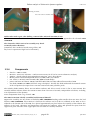
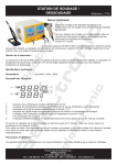
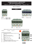
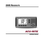
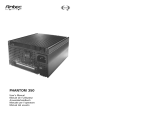
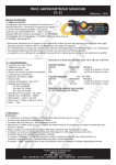
Failure analysis of Selectronic dynamo regulator version 3.2 1 Failed regulator Selectronic N°1, for Dynamo 6V 60W LUCAS.......................................................................2 1.1 General view................................................................................................................................................2 1.2 Function.......................................................................................................................................................2 1.3 Composition.................................................................................................................................................2 1.3.1 Printed circuit board.............................................................................................................................2 1.3.2 Pinout ..................................................................................................................................................2 1.3.3 Wires, wire mounting...........................................................................................................................3 1.3.4 Components.........................................................................................................................................4 1.3.5 Explanation of the stresses:..................................................................................................................5 1.3.6 Mounting of other components............................................................................................................5 1.4 Electrical measurements..............................................................................................................................6 1.5 Conclusions on the assembly of the regulator.............................................................................................6 2 Régulator N°2......................................................................................................................................................7 2.1 Measuring, values of components...............................................................................................................7 2.2 Observations................................................................................................................................................7 2.2.1 Back to correct.....................................................................................................................................8 2.3 Electrical tests..............................................................................................................................................8 3 Electronics modification......................................................................................................................................9 3.1 Reconstruction of schematics......................................................................................................................9 3.2 Remarks on design.......................................................................................................................................9 3.2.1 D1 diode : STPS15..............................................................................................................................9 4 Bike charge circuit.............................................................................................................................................11 4.1 the battery..................................................................................................................................................11 4.1.1 Discharge curve, ................................................................................................................................12 4.1.2 Temperature Coefficient ....................................................................................................................13 4.1.3 battery data sheet................................................................................................................................13 4.2 dynamo regulator ......................................................................................................................................14 4.3 The dynamo...............................................................................................................................................15 4.3.1 Lucas Dynamo...................................................................................................................................15 4.3.2 «Trick» for isolation check................................................................................................................16 4.4 The alternator.............................................................................................................................................16 4.4.1 Car type alternator..............................................................................................................................16 4.4.2 Bike Alternator ..................................................................................................................................17 4.5 alternator regulator.....................................................................................................................................17 4.5.1 Car type .............................................................................................................................................17 4.5.2 Bike regulator.....................................................................................................................................18 4.5.2.1 Rectifier......................................................................................................................................18 4.5.2.2 To regulate or nor to regulate ? (Lucas, prince of Darkness, William Sh.,1599).......................18 4.5.2.3 The Japanese...............................................................................................................................19 5 Conclusions.......................................................................................................................................................19 Zibuth27, 2012, Creative Commons (CC) by, nc, sa page 1/19 april 2012 Failure analysis of Selectronic dynamo regulator version 3.2 1 Failed regulator Selectronic N°1, for Dynamo 6V 60W LUCAS I was given this failed regulator for repair and comments. 1.1 General view Extarnal view of radiator PCB view, component side PCB view, bottom side 1.2 Function It is a dynamo regulator for 60W british dynamo (positive to earth), one could think that the field coil will drain no more than 6W, provided that the electromagnetic gain is 10. The dynamo will provide 10A if it was designed for 6V operation and 8A, if designed for 7,5V operation. I have not yet a dynamo for test (at the begin of this paper), and I work on estimates current/voltages, I take 10A before more precise informations. 1.3 1.3.1 Composition Printed circuit board Single side goldened, FR4 epoxy with solder mask ref 3801 D.L. Selectronic = well manufactured. Some insulation distances could have been slightly bigger, considered that there is no real estate problem, anyway the solder mask protects. Gol finish is OK because the quantity of of solder is big enough to dilute to an acceptable level the goldtin intermetallics. A double side PCB would ensure better holding of feedthrough components. The circuit was cleaned from flux residues after soldering of components, then, a second phase of manufacturing (connecting wires) was done, without cleaning. No general protection with varnish. 1.3.2 Pinout Red = + battery = ground Black = battery White = field Yellow = dynamo out A diode links wires yellow and black, avoiding current from battery to the dynamo, which uses the dynamo as a motor. All charge current flows through it. Zibuth27, 2012, Creative Commons (CC) by, nc, sa page 2/19 april 2012 Failure analysis of Selectronic dynamo regulator 1.3.3 version 3.2 Wires, wire mounting External link is made by wires 3mm dia, 16AWG copper = 1.29mm dia, section 1.31mm², specified 105°C. Good quality wire, registered UL (Underwriter's Labs), possibly made of PER (reticulated polyethylen), withstands better than PVC, thus allowing higher working temperature. Copper wire with metallic finish, bright grey, poor solderability. The wires are fed through the radiator in a 4mm dia hole, NO bonding NOT CONFORM. All wires are wounded by the radiator (not deburred on one side, fortunately, on this sample on inner side, where the wire moves less). Because the wires are NOT going through the PCB, the angle at the radiator varies, and the contact with the radiator may be hard. Two wires are oversized, they will only feed an amp or less. The main current flows in a section of 1.31mm², slightly overloaded, not a big concern, considered his short lenght. Because the hole in PCB is too small, the wires are butt soldered and can't get through. RECOMMENDATION = bond the wires to the PCB and to the radiator, Ideally, the wire should have a stress relaxing loop. Anyway the holes HAVE to be big enough or redrilled. • • Correct solder except big wires leaded solder (illegal for sale since 2006) The solder flux residues are cleaned on the PCB, except for added elements, probably added in a second phase of manufacturing : big wires and TO220 transistors. This may induce long term corrosion problem. NOT CONFORM, but probably not so important here because of the presence of solder mask and no high impedance circuitry No wire goes rhrough the PCB because the copper diameter is bigger than the hole ! So, the wires are butt soldered. A traction stress is not welcome here ! NOT CONFORM The red wire is very bad soldered : no wetting of the copper and an excess of solder flowed through the PCB hole (a touch of soldering iron showed that it not a wire going through the PCB, NOT CONFORM Zibuth27, 2012, Creative Commons (CC) by, nc, sa page 3/19 april 2012 Failure analysis of Selectronic dynamo regulator version 3.2 flowing of solder, not even correct on other side! Solder to be made again, after drilling a correct hole and total insertion of wire The transistor screwed on the radiator has a too sharp bending radius, and cracks appeared in the electrode NOT CONFORM The electrodes which survived to assembly, may break eventually under vibrations (remember, this is made for british vintage bikes, and they have a reputation of high level of vibrations) 1.3.4 • • • • • • • Components dated 3 = 2003 or 1993 Resistors : ALL in 1% tolerance = OK but not necessary for all (to be seen in schematics analysis) STPS15 = diode Schottky ST Semiconductor 45V, 15A, 175°C, NO radiator BD136 power transistor Philips PNP, 45V, 1,5A, 10W, 150°C, no radiator two C547 (= BC547) transistor NPN, 60V, 100mA, 0,5W Philips power transistor on radiator: TIP41C Fairchild NPN, 60V, 6A, 65W, soldered bottom side of PCB one diode 1N4007 1A 1000V field back surge absorption . Usually this diode withstand the nominal current of the coil protected, I expect then a 1A max current with some possibles peaks. The Schottky diode STPS15 allows 15A on infinite radiator, and able to work at 175°C (but at zero current) The assembly without radiator allows the current no more than a few tens of seconds, computation to be done, according to real parameters of the dynamo. Active components from « big » brands : OK The TIP41 transistor is badly assembled and destroyed himself! Hyperstatic assembly, not any chance of flexibility NOT CONFORM bending radius smaller than two times the lead thickness NOT CONFORM. The transistor is fixed on the radiator ans his leads are soldered on the PCB. As he is soldered to the bottom side of the PCB, he is placed approximately on place before the assembly of the radiator. The stiffness of the leads, vibrations and temperature increased the cantilever effect and splitted the epoxy from the copper base plate. The side of the copper plate are not visible in a healthy transistor. Zibuth27, 2012, Creative Commons (CC) by, nc, sa page 4/19 april 2012 Failure analysis of Selectronic dynamo regulator version 3.2 Broken transistor In fact the broken transistor could have been seen by very careful inspection (and by somebody aware of this very uncommon failure) the abnormal aspect of the transistor deep and bright black color for the normal part of the transistor, grey and finely grainy aspect of the broken part 1.3.5 Explanation of the stresses: The stress is in that direction (« effort »), because the vertical part (in this drawing) of the lead was slightly too long. The solder spot in this position gives a strong application point to the force. And the lengths are just short enough to avoid bending. It is possible than if the lead is too short, when the screw is torqued, the copper plate can be bended (restricting the thermal transfer), or the lift of the epoxy may occur on the other side. Film isolant=isolating sheet (silicon) semelle=plate of transistors soulèvement=lift up effort=stress In this assembly, the destructing effects of this design are dependent of the torque applied to the silicon sheet because of the « elasticity of the silicon sheet and of the nylon screw insulator. In addition to that, the solder spots are located i the worst place : exactly in the axis of the two PCB fixation screws ! Because it is now obvious that there is no electric relation with the remaining of the circuit, and the schematics seems simple, I simply replaced this transistor only. It works ! 1.3.6 Mounting of other components Diode STPS15 : the bending of the leads do not start at a minimum distance from the body NOT CONFORM, risk of moisture penetration and internal corrosion. In addition, the mounting without radiator does not allow the maximum current of 15A (there are specified by the manufacturer, only with correct radiator) Zibuth27, 2012, Creative Commons (CC) by, nc, sa page 5/19 april 2012 Failure analysis of Selectronic dynamo regulator version 3.2 diode BD136 BD136 One lead is bended too close to the body, we can see a black line showing separation bodylead. It is preferable to replace it. An example of more tolerant mounting of the transistor. This one was not a new one, that explains the irregularities. This transistor, was only used for checking the hypothesis of single failure. 1.4 Electrical measurements Regulated voltage (measured on lab power supply, not on dynamo circuit) = 8.26V. It is consistent with values I already observed on some Zener regulators for alternators, I don't say it is correct ! It seems to me that is a boiling voltage for the battery, and is probably not good for long term. For example in a 12V car circuit, the voltage is limited to 14.4V, (7.2V on « 6V » circuit). For reference purpose, the reference diode voltage is 5.48V. The regulator shows no linear behavior, (maybe for a few millivolts only). This proves the insensibility to individual characteristics of the transistors, allowing the replacement by any other, in the power range. For replacing the dead TIP41 (not knowing the exact need, I just want a type withstanding at least the 6A of the TIP41, I finally decided for a MJE3055 NPN, 100V, 15A, 90W, just because it was available in my drawer. Mounted obviously with short wires, so the PCB and the transistor on the radiator are now mechanically decoupled. RECOMMENDATION : dismount the TIP41, place linking wire between transistor and PCB of course, after checking the good health of the transistor, and shortening the leads to 5mm, because the solder has NOT to go up to the body, the copper diameter could be reduced to 1mm, considering the short lenght of 2cm max. 1.5 Conclusions on the assembly of the regulator Not knowing the schematics (not yet reconstructed, but knowing how a classic regulator should be), I ca say that the components are from good quality, some are overspecified (no need to bother to compute exactly the necessary power or precision) not a problem, only somewhat pricier (except schottky diode) Most of the PCB is well made, soldered and cleaned But the mechanical design is BAD (some points not conform to IPC 610 standard, class : toys). The mounting of the wires and specifically of the transistor TIP41 is BAD. This failure is the consequence of truth. In my (humble) opinion, it is necessary to : • change the assembly of the TIP41, and add wires to link the transistor to the PCB, change the transistor if any suspicion of stress • redrill the wire holes in the PCB and resolder them correctly • glue the transit of wire to the PCB This analysis was sent to Selectronic on March 2012, in hope (I had a dream) the future deliveries will be reliable Zibuth27, 2012, Creative Commons (CC) by, nc, sa page 6/19 april 2012 Failure analysis of Selectronic dynamo regulator version 3.2 2 Regulator N°2 Received in working condition Same model than the previous one 2.1 Measuring, values of components Same resistors on same place (thus no adjustment with different Zener diode) And we have then a different regulation voltage. regulation voltage Zener voltage = 8,77V (regulator #01 = 8.26V) = 5,79V (regulator #01 = 5,48V) 2.2 Observations • • • • The leads of the TIP41 have a good bending radius, OK the silicon isolation film is wrong placed under the TIP41, bad thermal transfer and electrical isolation, NOK Only one wire goes through the PCB, the yellow one. Bad solder wetting , NOK the PCB is not parallel to the radiator, due to the stress given by the wires and the TIP41, this one is OK PCB & radiator are not parallel, because of the stress on a wire. This wire is not in his hole, then misplaced bending radius of TIP41 almost correct, isolating film wrong (not totally under the transistor) Misplacement of film ; unexplained scratches on PCB bad solder : no wetting of wire (& not passing through the PCB) Zibuth27, 2012, Creative Commons (CC) by, nc, sa page 7/19 april 2012 Failure analysis of Selectronic dynamo regulator version 3.2 wound on all wires 2.2.1 Back to correct Simply back to standards with the recommendations : link wire from TIP41 to PCB, output wires correctly soldered in a bigger hole. Regulator back to standards slight melting of wire insulator because the the difficult wetting of the wire. Transistor linked to PCB via a wire The output wire is glued to the radiator 2.3 Electrical tests Obviously, no change in in regulated voltage. Test under load : 9Amps as the dynamo should give 10A, Negative margin, for a 10A system, the diode should withstand 15A As expected on the first sample (§1.3.4), the diode D1 blew up after one minute and half ! The diode is replaced by a MBR1545 (available from the same provider : Selectronic, price 1.3€) As the diodes are from the same chip, no problem of parallelization (30A total). The diode is placed on the radiator and the temperature rises now to 35-40°C at 9A, NOW the regulator becomes reliable Zibuth27, 2012, Creative Commons (CC) by, nc, sa page 8/19 april 2012 Failure analysis of Selectronic dynamo regulator version 3.2 3 Electronics modification For qualified people only, at your own risks 3.1 Reconstruction of schematics 3.2 Remarks on design Very classic schematics of regulator : differential amplifier + power amplification, open loop (very high gain). The dynamo voltage is controlled by compare the reference voltage (zener diode) to a part (bridge R3R4) of the output in an differential amp T1T2 . The output voltage is then shifted down from 0.2 to 0.5V, depending on current, we are far away from the 3% requested by Yuasa. In the case the transition voltage is too high, place additional resistor parallel to R3, in the case voltage is too low, place resistor on R4. 3.2.1 D1 diode : STPS15 As expected (§1.3.4, components) D1 diode heats up a lot : from 21°C to 130°C in a minute & half, no possibility to take into account the time constant, so the temp was significantly higher ! At this temp direct voltage drop is 0.5V at 9A, dissipation is 4.5W, you add 7.2°C for junction temp making 137°C. The PCB will degrade at these temps The data sheet shows that if the STPS15 is placed on PCB (but on the copper side) with 1.3 cm² of copper (the brutal change of slope in the curve), the thermal resistance is in the range of 45°/W, then 193°C above ambiant. Largely over the max: 218°C, as 175°C is allowed, but 175° at ZERO CURRENT ! Selectronic made a major design failure in the design of the regulator which may only be used at a fraction of the max dynamo current.. This diode NEEDS a radiator, In fact it can be mounted on the main radiator, with isolation film, thermal conductor, close to the TIP41 (dissipation 2 to 3W) Zibuth27, 2012, Creative Commons (CC) by, nc, sa page 9/19 april 2012 Failure analysis of Selectronic dynamo regulator version 3.2 It is better to use the MBR1545 available at the same Selectronic priced 1.3 €. This diode is made of two 15A diodes in the same chip,= same voltage drop, same temp coefficient, we have then a good operation margin. Radiator is MANDATORY, use the main radiator, care should be taken on the passage of wires. The best would be to regulate the true voltage of battery, first by moving the sense point of R4 to the output of the diode : the black wire, but compute first all effcts of this modification. Second possibility is to have a sense wire, connected to the battery itself, then it will be a true compensated regulator, those modification will be studied in an other paper. As it is the regulator requests to be set 0,5V above battery voltage, but the voltage drop to be compensated depends on the current, so 7.7V would make an acceptable trade off. The test was conducted with a 9 Amps current for a 8.5 Amps max current, but the temperature rise is then 191°C above ambient, still destructive. Zibuth27, 2012, Creative Commons (CC) by, nc, sa page 10/19 april 2012 Failure analysis of Selectronic dynamo regulator version 3.2 4 Bike charge circuit Just a reminder of basics, already supposed well known The bikes from my tests : BSA 350 & 250 from the fifties, back , my teenager : BMW R1100, 1997, 180 Megameters The charge circuit is made of a battery, a rectifier(if fitted with an alternator) and a source (dynamo or alternator). We are speaking of british bikes, therefore this (reversed) order. 4.1 the battery Leadacid for the bikes, almost no exception. Made of an assembly of cells called « 2V » because the voltage is around 2V per cell. 3 cells in series make a 6volt battery, 6 cells make a 12V battery. The 2V per cell varies around 2V, depending on the acid concentration, the charge status, the current, the TEMPERATURE, the technology (starter battery, buffer battery, gel battery, and the metals in the alloy : pure lead, with calcium, tin, selenium, silver, ...) The battery of the vintage british bikes is not intended for cranking motor, not able to give a current of several times his capacity. The capacity is given in Ah ampere hour and is theoretically the current for going from full charge to empty in an hour. It appeared soon that the apparent capacity depends on the discharge current, we use now a discharge in 20 hours. The measure unit in Ah comes from electrochemistry domain, related to the amount of coulombs transferred, supposed the current is constant, which never happens in reality ; an other unit issued from electricity domain is the watt hour Wh (it begins to be stamped on some camera batteries), but the power is not more constant. The main user in the vintage bikes is the lighting circuit where the current varies highly : a cold lamp drains 15 times more current than a hot lamp, during the time of heating up, and lamp current (and lamp duration) is very sensitive to the voltage. The only constant drain (constant resistance) is the coilbattery ignition system (Kettering ignition in USA), but ther are lots of magnetos out there. A starter battery shows two figures : capacity in Ah and the max current for short time (eg 60Ah 610A) Most values are given at temperature 20 or 25°C. A few manufacturers publishes the temperature coefficient, as a linear coefficient (range of 0.003V/°C) but reality is not that linear, straight line is only an approximation, in a temperature range. Zibuth27, 2012, Creative Commons (CC) by, nc, sa page 11/19 april 2012 Failure analysis of Selectronic dynamo regulator 4.1.1 version 3.2 Discharge curve, Measured on new bike battery 6V 4Ah : Amp A/h W/h Prix A/h Prix W/h batterie plomb 6V Tashima 6N4 R interne 0,100 0 5 10 15 20 25 30 35 40 45 50 55 60 65 70 75 80 85 90 95 100 105 110 115 120 125 130 135 140 145 150 155 160 165 6,04 6,04 6,04 5,81 6,16 6,04 5,81 5,86 5,86 5,86 5,81 5,81 5,81 5,75 5,75 5,75 5,69 5,63 5,69 5,51 5,51 5,39 5,10 4,34 3,99 3,69 3,52 3,11 3,05 2,87 2,70 2,52 2,29 2,17 1,285 1,285 1,285 1,235 1,310 1,285 1,235 1,248 1,248 1,248 1,235 1,235 1,235 1,223 1,223 1,223 1,210 1,198 1,210 1,173 1,173 1,148 1,085 0,923 0,848 0,786 0,749 0,661 0,649 0,611 0,574 0,537 0,487 0,462 0,000 0,214 0,428 0,634 0,853 1,067 1,273 1,481 1,689 1,896 2,102 2,308 2,514 2,718 2,922 3,125 3,327 3,527 3,728 3,924 4,119 4,311 4,492 4,646 4,787 4,918 5,043 5,153 5,261 5,363 5,459 5,548 5,629 5,706 0,000 1,294 2,587 3,783 5,127 6,421 7,616 8,835 10,055 11,274 12,469 13,664 14,859 16,031 17,202 18,373 19,520 20,644 21,791 22,869 23,946 24,978 25,901 26,569 27,133 27,617 28,056 28,399 28,728 29,021 29,279 29,505 29,690 29,857 0,000 36,884 18,442 12,456 9,266 7,406 6,208 5,336 4,679 4,166 3,758 3,423 3,142 2,907 2,704 2,528 2,374 2,240 2,119 2,013 1,918 1,833 1,759 1,701 1,650 1,606 1,567 1,533 1,502 1,473 1,447 1,424 1,403 1,384 0,000 6,107 3,053 2,089 1,541 1,230 1,037 0,894 0,786 0,701 0,634 0,578 0,532 0,493 0,459 0,430 0,405 0,383 0,363 0,345 0,330 0,316 0,305 0,297 0,291 0,286 0,282 0,278 0,275 0,272 0,270 0,268 0,266 0,265 date 02/04/12 Ratio 0,0586 ddp vide 6,51 R--> 4,7000 Prix 7,9 utiliser avant tension 7,00 6,00 5,00 4,00 volts Volts Volts 3,00 2,00 1,00 0,00 0 20 40 60 80 100 120 140 160 180 minutes tension = voltage capacité=capacity décharge=discharge capacité capa minutes 6,000 6,000 5,000 5,000 4,000 4,000 3,000 3,000 2,000 2,000 1,000 1,000 0,000 A/h 0,000 0 20 40 60 80 100 120 140 160 180 minutes décharge Tashima 6N4 charge Tashima 6N4 C/2 C/3 6,50 9,00 6,00 8,50 5,50 8,00 Volts 4,50 tension volts 5,00 fem 4,00 Volts 7,50 7,00 3,50 6,50 3,00 6,00 0 2,50 0 50 100 150 200 20 40 60 80 100 120 140 minutes minutes typical chargedischarge curve on a bike, pilot and regulator don't use normally a gravity meter while riding, so I'm interested in the volts per cell values. We may deduce from this that the floating value correspond approx to 80% charge for 6V battery, multiply by 3 for 12V battery, multiply by 6 Zibuth27, 2012, Creative Commons (CC) by, nc, sa page 12/19 april 2012 Failure analysis of Selectronic dynamo regulator 4.1.2 version 3.2 Temperature Coefficient The temperature coefficient depends on acid concentration (therefore from the charge status) PowerSonic publishes this chart for his 12V 4.5Ah sealed leadacid battery The corresponding thermal coefficient 0 to 40°C is 0.006V/°C Another curve, corresponding to a unique charge status. The corresponding thermal coefficient, linearized between 0 and 40°C is +0,004 V/°C. 4.1.3 battery data sheet Yuasa data –difficult to get this level of document quality from other manufacturers I tried: Exide Bosch, …, I found only PowerSonic to have such usable docs floating voltage is the voltage with no current in or out of the battery. I use this document as standard value for bike batteries. The values can be transposed to other members of th NP family, hermetic battery, valve protected, gas recombination (VRLA). The cyclic charge corresponds to bike use : charges/discharge and requests précision of 3% soit ±0,072V/élément on 6V battery makes ±0,21V = 7,47Vmax et 7,04Vmin the Selectronic regulator with measured voltage of 8,26 and 8,77V is offspecs Yuasa , even with Schottky diode between dynamo and battery, The Lucas regulator with 7,8V typic is still off specs the thermal coefficient is 0.004V/°C, in accordance with Wikipedia USA in cycled use : 7,02V at 40°C and 7,5V at 0°C. The regulators Lucas , and worse Selectronic, are off Yuasa specs, which induces a reduced lifespan But using a battery manufactured in 1950, impossible to get one in working condition ! Zibuth27, 2012, Creative Commons (CC) by, nc, sa page 13/19 april 2012 Failure analysis of Selectronic dynamo regulator version 3.2 The tested Tashima battery, has the voltage (at 23°C) going from 6.04 to 5.51V when the battery, always connected to the same load resistor (4.7 ohms) has his charge status goeing from full charged to full discharged. The emf should be normally measured, any load/charging circuit disconnected since a certain time, say half an hour after disconnecting the load. This is a boring measurement, I simply computed a value of internal resistance at begin of measurements, from the difference loadedunloaded. Deducted from the internal resistance, I extracted an instant emf (no settling time of 30 mins) in the curve discharge at C/3 : the red curve fem (emf in french) The discharge , once the 4Ah drained, the voltage drops rapidly AND we are in the sulfatation zone. I sacrificed a part of the lifespan here (but at a price of less than 8€, I can afford it). The manufacturer choosed to stop discharge at that value, we can see that we can extract some more energy, I went up to 5.7Ah. Remember, the more deeply you discharge, the less the battery withstands a number of charge cycles. You better choose the biggest capacity which fits to the compartment (and electrodes position), it lasts longer. The vintage BSA 350 has a battery of 6V 12Ah, the dynamo gives 8.5A at 7.5V, the maximum charge current is C/1.6. 4.2 dynamo regulator Many vintage bikes from the fifties use the Lucas MCR2 regulator, adapted to the E3L dynamo (diameter 3 inches=7.62cm), this is a two coils regulator, well manufactured (for his time). It is made of • one voltage regulation coil • one coil to avoid the current going INTO the dynamo (cutout coil) The voltage coil is adjustable on a few parameters • the gap of the contacts • the stiffness of the spring As soon the desired voltage is reached, the contact opens, making a vibrating contact (around 100Hz) The adjustable spring (visible on the picture : the vertical parallel lines, just on the left of the coil) is in fact bimetallic (like in many thermostats) and acts as the thermal compensation wanted by Sir Lucas : Extracted from service manual 10°C 7,9V min7,7 max 8,1 20°C 7,8V min7,6 max 8,0 30°C 7,7V min7,5 max 7,9 40°C 7,6V min7,4 max 7,8 makes a thermal coefficient of 0.01V/°C, which means the temperature is somewhat compensated. The voltage regulation coil has additional 4 wounds of thick wire (diameter 2mm), the main dynamo current flowing through. This compensates the voltage drop in a typical cabling from dynamo to battery : « compensated regulator ». Good manufacturing quality! The Selectronic regulator, and probably other electronics regulators do not have this compensation feature, which needs a current sensor, and a 10 Amps sensor is very visible, the use of a diode as sensor is not an easy task. A good solution is a sense wire directly connected to the A output from the regulator, or better, to the battery terminal. The Selectronic regulator miss two important features : wiring resistance and temperature compensations. Regulation voltage Selectronic : 8.77 or 8.26, Sir Lucas : 7.9Vtyp (@10°C) and 7.6Vtyp (@40°C) One cannot claim that Selectronic has a higher voltage in order to compensate the voltage drop in the circuitry, as it is always too high, low or high current ; Lucas regulator has a antiohmic behaviour, his output voltage is higher on high current, so, considering the average cabling circuitry, the battery voltage remains constant (at same temperature, of course) Ideally the schematics of the Selectronic regulator has to be modified by adding temperature compensation and Zibuth27, 2012, Creative Commons (CC) by, nc, sa page 14/19 april 2012 Failure analysis of Selectronic dynamo regulator version 3.2 adding a sense wire. The other coil (cutoff) opposes the magnetic field created by the main current, to the field created by a voltage coil : as soon as the current wants to go from the battery to the dynamo, the current is stopped. This coil is replaced by a diode (mandatory a Schottky diode for lowering the voltage drop). In the car world, there is a third coil, for current regulation. There is a spike voltage limitation on the vibrating contact, made with a pellet resistor (the black disc with green paint stripe, firmly pressed against the armature for heat dissipation) value : 50 ohms. This contact wears out, even covered with platinum or tungsten, specifically because of the functional vibrations 100 openings per second, making a million operation in less than 3 hours. Obviously, there is no longer any spare part available. An electromagnetic regulator, when the voltage is not reached, shortens rotor and stator (called here field and armature), the residual magnetic field creates a small voltage in (rotating) armature, which, in turn, creates a higher voltage, the dynamo, after this autostart loop, reaches finally the regulation voltage. It happens that, after some position in the earth magnetic field or exposure to leakage of alternative magnetic fields (motors or transformers), the residual field in dynamo becomes too low for the autostart feature, it is necessary to connect temporary field and armature together shortly to a battery with correct polarity. Take care that the dynamo works then as an electric motor. For the wise guys: don't expect to have invented a cranking device, the usable torque is way from enough ! The Lucas regulator has two « voltage » coils connected to the dynamo output, making 13 ohms resistance which drains 0,57 Amps, an electronic regulator drains only a few milliamps. 4.3 The dynamo 4.3.1 Lucas Dynamo Made of a fixed inductor (Field coil) 2,8 ohms and a rotor (called armature) with brushes (0.5ohms rotor+brushes) for rectifying and collecting current. It is an electric machine, able to work as a motor if current flows TO the dynamo. The E3 series have a diameter of 3 inches (76.2mm). dynamo Lucas E3L : the dynamo is not designed with axial symetry, only one field coil ! rotor brush side I finally got the electrical parameters of the E3L dynamo (J Gardner revised by Hancock) : Field coil = 2.8 ohms rotor resistance (armature) = 0.55 ohms, including brushes max output voltage 7.85 V at 8.5 Amps This is intended for charging the battery at 7V through a regulator resistance of 0.1 ohms (voltage drop 0.85V). This not a full charge, only between float and cycle charge, around 70% of full charge, but is at full load of 60W. It is not possible to measure correctly these resistance values with a normal multimeter, even an electronic one. Zibuth27, 2012, Creative Commons (CC) by, nc, sa page 15/19 april 2012 Failure analysis of Selectronic dynamo regulator 4.3.2 version 3.2 «Trick» for isolation check I often heard this wise guy trick for isolation check: put a few watts lamp in series, and use the 220V mains. NEVER do it ! Aside the lethal risks, specially with a quick and dirty setup, this can create a failure on device with no 6V problem, or increase an existing leakage. Remember, when you speak about 220V, the reality is a peak/peak 622V, the destructive spark is sensitive to peak voltage, a lamp is sensitive to the average current, RMS to be precise). In addition the current is variable : cold starting current is 15 times higher than steady current, a 20W bulb starts at 1.35Amp and runs with 90mA (the filament temperature is 3000°C and the temperature coefficient is 0.5%/°C). Sparking risk : with a 600V peak, if two unsinsulated conductors are separated by a 0.2mm gap, there is a destructive spark, which never would have caused any trouble on 6V. The 220V 20W bulb never replaces a specialized device like high voltage megohmmeter (with limited current). 4.4 The alternator The alternator generates alternating current, obviously. The battery needs direct current. Alternating current is measured in RMS value : the equivalent DC current for thermal effect, like in a lighting bulb. The alternator can be used for the lighting system but the output current varies as the rotation revs up or down, 6V at 1000rpm makes 30V at 5000rpm ! The AC is expressed in RMS (root mean square, which is the computation of this current) this means the equivalent thermal effect of a DC current. For a pure sinus current the peak/peak voltage is expressed as 2 x √2 times the DC value, so a 6V RMS makes 17V p/p. 4.4.1 Car type alternator Exists in some big bikes BMW, Goldwing, Guzzi, ... The inductor is rotating (rotor), powered by brushes, with lower current than the output (this acts like an electromagnetic gain). The shape of the polar pieces determines the voltage form (sinus, trapeze). The stator gives the main current (40 to 80Amps) is fixed. The rectification is made in the alternator with silicon diodes pressed in the radiators, in the air flux for cooling. The circuits are three phases, with fullwave rectification, this makes a minimum voltage ripple. Contrary to car dynamo, there is no need to limit the current, the designed magnetic saturation limits the current. Magnetic saturation Zibuth27, 2012, Creative Commons (CC) by, nc, sa page 16/19 april 2012 Failure analysis of Selectronic dynamo regulator 4.4.2 version 3.2 Bike Alternator Generally limited to 200W, made with strong magnets placed on the crankshaft. Suzuki GSX400 1981 rotor rotating around stator stator fixed on the cover, inside the rotor The rectification is made with an external diode bridge, it was selenium diodes for the first vintage bikes, now silicium diodes, integrated with the regulator since the seventies. There were no regulation on the beginning of alternator use, simply switching of one or several coils when using lighting. The choice was to have the correct voltage on hi rpm only, at low rpm lighting was poor (Lucas, prince of Darkness). The voltage is directly dependent of rpm if 6V at 1000rpm, it goes to 30V at 5000rpm, and the lamps are extremely sensitive to overvoltage (inversely proportional to V to the sixteenth power = an overvoltage of 16% reduces the lifespan to 10% of normal) chart from the british Lighting Industries Federation 4.5 alternator regulator 4.5.1 Car type Integrated in the alternator, generally in a module close to the diodes. The diodes request air cooling, provided by the air flowing through the alternator, This air is already heated up by the coils, and by the diodes, before reaching the regulator, therefore the temperature is not related to the battery temperature (which was the case with dynamos, when the regulator was laced near the battery), so there is no way to implement temperature compensation. The voltage is generally regulated to 14.4V, which is not a 100% charging. The alternator requests a 12V system as the voltage drop of 12V is too important for 6V. On the same time, was the introduction of the nomaintenance batteries. Zibuth27, 2012, Creative Commons (CC) by, nc, sa page 17/19 april 2012 Failure analysis of Selectronic dynamo regulator 4.5.2 version 3.2 Bike regulator 4.5.2.1 Rectifier Replaces one function of the brushes, was copper/copper oxide at the beginning, then selenium. The reliability was very poor, with addition of some leakage current, draining the battery. Since the seventies, the rectifier is made of silicon. The voltage on half wave provides a high ripple, the 3phase fullwave rectification provides almost no ripple. 4.5.2.2 To regulate or nor to regulate ? (Lucas, prince of Darkness, William Sh.,1599) On the beginning, « regulation » was made by switching the coils between day or night, because on these times, it not mandatory to ride with headlights on during the day. Today, although it exists in France, a law allowing not to ride headlight on, for bikes older than 1962, the cops arrest you frequently, making believe they don't know this law (real stupidity or tactic from law enforcement forces ?) but look carefully on your tyres, in any case, you better have a copy of this law in your wallet ! Because of basic electromagnetic laws (voltage depends primarily on the rotation speed), the only possible choice was to have full charge only at high rpm. This is a possible cause for the nickname « Lucas, prince of Darkness ». As electronics was not well developed at these times (to affordable price), Lucas, as many others used at first hand the pilot's hand (switch), later on used Zener diodes : zerro current at low voltage (in silicon, leakage current is in the microamps range), at the Zener voltage, the current becomes suddenly limited only by external resistors, the zener limits therefor the voltage, and dissipates the excess in heat, big radiator needed ! Lucas alternators are monophase : the magnets travels on the same time in front of the corresponding polar pieces. First type: a third of alternator is used for charging the battery. Two thirds are used for lighting, no regulation at all. Second type: a Zener diodes limits voltage (and heats up) one third of coils is added for lighting. In the case of magneto ignition, one third is used for charge, tho thirds added for lighting. Full wave rectifier. Third type: two Zener diodes, must be paired, for equalizing heating, else on heats up a lot and destroys himself, the second following soon. It is a half wave rectifier, and half of the power is usable with high ripple of voltage. Zibuth27, 2012, Creative Commons (CC) by, nc, sa page 18/19 april 2012 Failure analysis of Selectronic dynamo regulator version 3.2 4.5.2.3 The Japanese All Japanese use triphase alternator and the rectifier is in the same module. All Japanese since the seventies use the same regulation scheme, with thyristors. The thyristor is a memory power switch, once triggered with a small grid current, it remains ON up to next zeroing of voltage or current. Thats perfect, as the alternator produces alternating current, which regularly switches OFF the thyristors. The thyristor is obviously not mounted on the battery side : once triggered, it will only switch off when the battery is emptied to zero or when it disappears in a puff of smoke (stinky!). The thyristor is triggered by a zener diode as soon as the voltage becomes too high, and switches off next voltage inversion. The alternator saturates and has no damage from this shortcircuit. The schematics is the same for all Japanese bike manufacturers, only the amount of thyristors may vary : one or three, three is the better. standard schematics for Japanese rectifierregulator 5 Conclusions The regulators from British vintage bikes do not respect the specifications of battery manufacturers, which reduce in fact their lifespan. The electromagnetic regulators show a rapid wearout and are replaced by electronics. One electronic regulator, made by Selectronic in France uses good quality components, but the design and one poor manufacturing phase, give a poor reliability (numerous claims on the Web). The correction of some design errors is though easy and cheap, and it is recommended to adjust their voltage. Zibuth27, april 2012 Zibuth27, 2012, Creative Commons (CC) by, nc, sa page 19/19 april 2012