1
Novel EOD Robot Design with a Dexterous Gripper and Intuitive Teleoperation A Major Qualifying Project submitted to the faculty of Worcester Polytechnic Institute in partial fulfillment of the requirements for the Degree of Bachelor of Science Submitted by: Matthew W. Carey (RBE/ECE) Eric M. Kurz (RBE) Joshua D. Matte (ME) Timothy D. Perrault (RBE) Advised by: Professor Taskin Padir Advisor Code: TP1 Project Code: BDR1 April 22, 2011 Abstract This paper details the design and implementation of an intelligent explosive ordinance disposal (EOD) robot to provide law enforcement agencies with a cost effective and reliable robotic platform. The key features of the robot include an intuitive user interface which provides additional sensor feedback and enhanced visual awareness compared to existing systems, an onboard three degree of freedom manipulator arm providing an enlarged workspace, and a dexterous gripper allowing for the removal of detonators. The flexible and modular robot design utilizes commercial off the shelf components for ease of maintenance and repairs. The robot provides a safe distance threat assessment and increased capacity for explosive ordinance disposal, improving the effectiveness of bomb disposal teams. The robot‘s low-cost, intuitive operation and ease-of-maintenance promote its widespread appeal, thereby saving the lives of both law enforcement personnel and civilians. i Contents Abstract ............................................................................................................................................ i Table of Figures .............................................................................................................................. v Table of Tables ............................................................................................................................. vii Bomb Disposal Robot Prototype .................................................................................................... 1 I. Introduction ............................................................................................................................. 2 II. Background .......................................................................................................................... 4 A. Market Research:.............................................................................................................. 4 B. Sensor Feedback ............................................................................................................... 6 C. Controls and Control Software ......................................................................................... 6 D. Mechanical Systems ......................................................................................................... 9 E. Network Communication Methods .................................................................................... 15 F. Hardware Components....................................................................................................... 18 1. Motor Controllers ........................................................................................................... 18 2. Communicating with motor controllers ......................................................................... 23 3. Robot Controller............................................................................................................. 25 4. Cameras: ......................................................................................................................... 28 5. Batteries:......................................................................................................................... 31 G. Summary ........................................................................................................................ 32 III. Methodology ...................................................................................................................... 33 IV. Mechanical and Hardware Design ..................................................................................... 35 A. Arm Design .................................................................................................................... 36 B. Gripper Design ............................................................................................................... 38 C. Base Design .................................................................................................................... 40 D. Sensor Suite .................................................................................................................... 41 ii E. Control Hardware............................................................................................................... 43 F. Controller ........................................................................................................................... 44 V. Design of Software and Communication Systems............................................................. 45 A. Network Communication ............................................................................................... 45 B. Onboard Processing........................................................................................................ 48 Ethernet Parsing ..................................................................................................................... 48 Safety System ........................................................................................................................ 49 C. Motor Control System .................................................................................................... 50 D. Programming the Controller Unit .................................................................................. 53 Controller Software ............................................................................................................... 53 GUI Layout ............................................................................................................................ 56 Displaying Video Feeds ............................................................................................................ 57 Threads ...................................................................................................................................... 57 Packet Structure......................................................................................................................... 58 VI. Controller Design ............................................................................................................... 59 A. Introduction: ................................................................................................................... 59 B. Iteration 1: Standard PID Loop ...................................................................................... 59 C. Iteration 2: Standard PID Loop and Experimental System Model................................. 61 D. Iteration 3: Position and Velocity Control ..................................................................... 62 E. Iteration 4: Position and Velocity Control (with slew rate added) .................................... 64 VII. Results ................................................................................................................................ 66 A. Finished Robot Specifications........................................................................................ 66 B. Mechanical Systems ....................................................................................................... 69 C. User Interface ................................................................................................................. 70 D. Wireless Capabilities ...................................................................................................... 71 iii E. Cost Analysis ..................................................................................................................... 72 VIII. Recommendations for future development .................................................................... 74 IX. Greater Impacts .................................................................................................................. 75 X. Conclusions ........................................................................................................................ 76 XI. Acknowledgements ............................................................................................................ 76 XIII. References ...................................................................................................................... 77 XIV. APPENDICES:............................................................................................................... 80 A. Appendix I: Parts List .................................................................................................... 80 B. Appendix II: Electrical Pin out for sbRIO ..................................................................... 82 C. Appendix III: Packet Overview...................................................................................... 87 D. Appendix IV: Mechanical Drawings of Key Components ............................................ 90 E. Appendix V: User Manual ............................................................................................... 102 iv Table of Figures Figure 1: Blast Suit ......................................................................................................................... 2 Figure 2: The Team with the Andros F6A Robot ........................................................................... 5 Figure 3: Visual Arm Position Feedback of the Andros F6A Robot .............................................. 6 Figure 4: Andros UI Display Screen ............................................................................................... 7 Figure 5: The Talon Controller ....................................................................................................... 8 Figure 6: The Andros Controller..................................................................................................... 8 Figure 7: MURV-100 High-Rise Arm for Aircraft Applications [6] ............................................. 9 Figure 8: iRobot‘s Packbot Fires a Disruptor [21]........................................................................ 12 Figure 9: Comparison of Tracked vs. Wheeled Vehicles [10]...................................................... 13 Figure 10: Andros F6A Wireless Tranciever ................................................................................ 17 Figure 11: Andros Dash with Fiber Optic Cable .......................................................................... 17 Figure 12: PWM control at different duty cycles [14] .................................................................. 19 Figure 13: H-Bridge Circuit [11] .................................................................................................. 20 Figure 14: Cytron Motor Controller [5] ........................................................................................ 20 Figure 15: Sabertooth Motor Controller [7].................................................................................. 21 Figure 16: SyRen Motor Controller .............................................................................................. 21 Figure 17: Pololu Motor Controller .............................................................................................. 21 Figure 18: Simple-H Motor Controller ......................................................................................... 22 Figure 19: Black Jaguar Motor Controller .................................................................................... 22 Figure 20:CANBUS [23] .............................................................................................................. 24 Figure 21: RS232 Architecture [4] ............................................................................................... 24 Figure 22: Ethernet Packet Structure [13] .................................................................................... 25 Figure 23: sbRIO 9612 [25] .......................................................................................................... 26 Figure 24: Axon II [6] ................................................................................................................... 27 Figure 25: FRC Controller [19] .................................................................................................... 27 Figure 26: Axis 214 PTZ camera [5] ............................................................................................ 30 Figure 27: Axis 212 Wide Angle Camera [5] ............................................................................... 31 Figure 28: Final Robot Design Overview ..................................................................................... 35 Figure 29: Kinematics Analysis of Arm ....................................................................................... 37 Figure 30: Inner Gripper Design Shown with Closed, Half and Full Open Configurations ........ 39 v Figure 31: Physical Gripper .......................................................................................................... 40 Figure 32: Gripper CAD Model .................................................................................................... 40 Figure 33: Robot Sensor Suite ...................................................................................................... 41 Figure 34: Hardware systems overview ........................................................................................ 44 Figure 35: Wi-Fi Rates [2] ............................................................................................................ 45 Figure 36: 802.11 Bandwidth Layout [7] ..................................................................................... 48 Figure 37: Safety System Diagram ............................................................................................... 49 Figure 38: Cascaded PID Arm Control System ............................................................................ 51 Figure 39: Labview programming ................................................................................................ 52 Figure 40: Gamepad Control Pin-out............................................................................................ 54 Figure 41: Graphical User Interface Display ................................................................................ 56 Figure 42: PID Equation ............................................................................................................... 60 Figure 43: Oscillation motion, PID Simulation ............................................................................ 61 Figure 44: Linearization for Dynamic Model of Robot Arm ....................................................... 62 Figure 45: Cascaded Control Loop ............................................................................................... 63 Figure 46: Saturated Velocity Controller ...................................................................................... 63 Figure 47: Cascaded PID, Slew Rate Added ................................................................................ 65 Figure 48: Front View ................................................................................................................... 69 Figure 49: Side View .................................................................................................................... 69 Figure 50: Link quality and strength as a function of distance from controller. .......................... 72 vi Table of Tables Table 1: Gripper Claw Comparison .............................................................................................. 10 Table 2: Comparison of key features of competitive EOD robots. Values dependent on accessories installed. ..................................................................................................................... 15 Table 3: Motor Controller Summary Table .................................................................................. 23 Table 4: Arm Drive Information ................................................................................................... 36 Table 5: D-H parameters of arm ................................................................................................... 36 Table 6: Acceleration and Maximum Speed Testing Results ....................................................... 40 Table 7: Analysis of Initial Design Specifications ....................................................................... 67 Table 8: Axis Camera Donation ................................................................................................... 73 vii Bomb Disposal Robot Prototype A video of the robot in action can be viewed online at: http://www.youtube.com/watch?v=vjDu2mlHDTQ 1 I. Introduction In the past decade, robotic systems have been used with increased popularity for explosive ordnance (EOD) missions. Advances in robotic technology have made it possible for robots to perform functions previously only possible by human workers wearing a blast suit as shown The primary advantage to using robotic systems for explosive ordinance disposal is the reduced risk to humans. Currently, EOD robots are able to traverse a variety of terrain, collect and destroy certain explosives and provide improved reconnaissance capabilities to law enforcement and military agencies. Although far from perfected, these robots are saving lives by finding and disposing of explosives without the need for direct human contact. In a press conference in Washington, D.C. in April of 2004, Cliff Hudson, the coordinator of the Joint Robotics Program of the U.S. Department of Defense stated that: “The bad news is we’re losing the units in the field. And the good news is we’re losing the units in the field. Every one lost is a soldier’s life saved.” [2] Some of the drawbacks to using robotic systems for these missions are the difficult and complex control systems, lack of dexterity, and lack of sensory feedback. Additionally, the high cost of these systems greatly limits their availability, especially to small law enforcement divisions with limited budgets. EOD Figure 1: Blast Suit robots generally cost upwards of $250,000 depending on size, mission capabilities, and available tools. Since bomb technicians have a higher success rate than robots due to increased dexterity, visual awareness, and the ability to make quick movements and adjustments, many bomb crews still prefer to send in a human technician for smaller explosives in order to protect their investment from being destroyed by a small explosive. As a result, bomb technicians are frequently placed in harm‘s way to perform missions that could be neutralized by robots. Despite the cost, bomb disposal robots continue to sell to both military and law enforcement agencies because of their invaluable role in threat detection and neutralization. On 2 April 12, 2011 iRobot Corporation of Bedford, Massachusetts signed a $230.1 million contract with the U.S. Navy to provide them with EOD robots [16]. The functionality of existing robotic systems has continuously improved over the past decade allowing them to perform an increased range of tasks. Some robots incorporate longer arms with increased degrees of freedom for improved dexterity and reach, different gripper designs for improved manipulation, and better cameras for improved visual awareness. Although much progress has been made in advancing the capabilities of EOD robots, there is still much work to be done. Most robots are unable to disarm detonators (primary explosives that trigger larger secondary explosives), due to lack of dexterity and the need for opposable motion. Control systems are often confusing and require lengthy training sessions before the operator can even move the robot. Furthermore, the sensor feedback from existing robots is severely lacking or nonexistent, making it extremely difficult for the operator to perform desired tasks. The goal of this project is to design and prototype a cost-effective bomb disposal robot with improved functionality, dexterity, and situational awareness in order to reduce the need for placing explosive ordnance technicians in harm‘s way. Some of the key areas that will be focused on in this prototype include a decreased production cost, improved sensor package, more dexterous gripper, and more intuitive control systems. 3 II. Background EOD robots come in a variety of shapes and sizes with a wide range of available features. Each system may vary in the mechanical design, communication and control systems. This section aims to outline the research performed on existing robot systems before design work began. This phase involves investigating exiting EOD robot systems and performing basic market research to determine desirable and undesirable features. The key aspects of research include: a. Market Research: Involves interviews with bomb technicians to review advantages and flaws of currently available robots. b. Sensor Feedback: Explores basic sensors that would aid in EOD missions. c. Controls and Control Software: Study of the controller and GUI software and the hardware control architecture. d. Mechanical systems: Research into the mechanical design of robot systems including base, arm, and gripper design. e. Communication Research into current methods of communication and review of the systems currently used on robot systems. Further research was performed to determine range requirements and signal limitations and restrictions. f. Hardware components: All other hardware components such as controllers, batteries, motor controllers, and sensors were researched. A. Market Research: Basic market research was performed to understand the key desirable features of existing robot platforms. A large portion of this information was obtained through an interview with the Boston Bomb Squad. In this interview, the team investigated three primary robot platforms including the Talon by Foster Miller, the Remotec Andros F6A and HD-1 robots by Northrop Grumman. Other smaller systems were also discussed and demonstrated for comparison and explanation of key features. A picture of the team with the Andros F6A robot can be seen in Figure 2. From these discussions, several key areas for improvement were unveiled. 4 Figure 2: The Team with the Andros F6A Robot One area of improvement for EOD robots is the use of sensor feedback. Many robots, such as the Andros robots, rely solely on visual feedback for remote operation, requiring the technician to aim a camera down towards a chart on the arm as a method of avoiding collisions with other components of the robot (shown in Figure 3). Similarly, many of the investigated robots have no method to detect how far away the gripper is from an object, making it very difficult to grab or lift objects, much less attempt to disarm bombs. Another key deficiency in several existing platforms is the complexity of operation. Many commonly used control units are riddled with switches and dials and require extensive training for robot operators. A desirable feature in EOD robots is a gripper capable of disarming blasting caps or detonators. Bomb technicians from the Boston Bomb Squad noted that an ideal method to disarm detonators would be through the use of a small gripper claw that protrudes from the center of a larger griper. This would provide the ability to pull the detonator relative to the explosive device. Currently this feature does not exist in any EOD robot systems, making detonators the only method of bomb disposal. 5 The method of communication is often costly can lead to a range of problems. Wired communication is commonly performed using fiber optic cable. Fiber optic cable is highly susceptible to breaking and can be crushed by passing vehicles or the robot itself. For the robots that do not use fiber optic cables, wireless radio transmission B. Sensor Feedback There is an apparent lack of sensor feedback in the current EOD robots on the market. This problem could be easily solved with the addition of simple sensors such as potentiometers, limit switches, range finders, and pressure sensors. Potentiometers could be used to provide the operator with real time position feedback from all links of the robot arm. Limit switches would increase the safety of the system and prevent the robot from colliding with its own systems. Range finders would allow more precise alignment of the gripper and arm while pressure sensors would allow the operator to cautiously grip delicate objects. Figure 3: Visual Arm Position Feedback of the Andros F6A Robot C. Controls and Control Software Each EOD robot manufacturer has a unique user interface to control their robots. These user interfaces vary from applications that run on standard computers to custom built units. The MARKBot uses a control program that can be installed on any windows computer with wireless capability. This program takes input from an Xbox 360 controller allowing the user to send input to the program about how to drive and control the arm. The program pulls up a 6 control interface when it detects a robot on the network. This control interface includes feedback about the status of the robot as well as information indicating what robot is connected. The information displayed on the interface includes the battery voltage, signal strength, internal temperature and GPS location. There is also a button to press to bring up the video feed form the robot‘s camera. The advantage of this control system is that it uses a very similar control system to that used in a number of video games that the majority of solders have played. The Andros robots use a custom made interface as shown in Figure 6. The interface consists of a control panel with a series of switches and knobs to control the different actions of the robot as well as a video screen to show the camera feedback. The Andros robot has four onboard cameras, yet only one feed can be seen at any given time (see Figure 4). Next to the screen there are controls for the volume of a speaker on the robot and headphones attached to the UI. The control panel is divided in to three sections. The first section controls the different aspects of the cameras, such as which camera is displayed, the zoom, focus and a variety of other controls. The second section of the control panel controls the physical motions of the robot, such as the position of the arm, driving and control of the claw. The third section of the controls is for attachable tools such as disrupter. The advantage of this control system is that it allows control of each possible action of the robot. Figure 4: Andros UI Display Screen The Talon control system is very similar to that of the Andros robot and can be seen in Figure 5. The self-contained unit is opened like a briefcase to reveal a panel of switches and dials and a display monitor. The controller contains a microphone and speaker to allow verbal 7 communication through the robot. Although this control system provides several different modes and controls, it is not intuitive for first time users. Figure 5: The Talon Controller Figure 6: The Andros Controller IRobot‘s PackBot is sold with a control unit that consists of a standard computer as well as a game controller. The controller uses a program that displays different camera views and includes a virtual 3-D model of the robot. The program also displays the battery power as well as the strength of the communications signal. This control system of this robot has the advantage that the user can easily tell the position of the robot without having to resort to using the cameras or guessing as is necessary with many of the other robots. With this model the user can avoid running the arm of the robot into other sections of the robot. This is much more difficult to do by using the cameras. There are a number of program languages that include the capability to create user interfaces. C++ has libraries that allow easy creation of a user interface. Java has a similar system with a couple of different options for what library to use. The java swing library allows for easy and quick construction of a graphical user interface, or GUI. This library includes objects such as buttons, text boxes and panels. By using these objects it is possible to create any user interface that can be thought of. There are two main ways to create these interfaces the first is by writing code directly then testing it. The second method to create a GUI is to use a tool that is specifically designed to create a user interface such as NetBeans. 8 SWT and AWT are java libraries that are designed to be used in the same manner as the swing library. The libraries for C++ are also built with the same concepts in mind as the swing library. D. Mechanical Systems Manipulator Arm EOD robots require some form of arm to perform basic functions. This arm can range from a short linkage to hold a disruptor to a large six degree of freedom robotic arm with gripper claw. The arm design will vary depending on the robot‘s utility, but the basic ability to reach and manipulate the targets is important to all systems. Figure 7: MURV-100 High-Rise Arm for Aircraft Applications [6] The arms ability to reach the target is often hard to predict because bomb threats can occur in a wide range of locations including vehicles, trash cans or dumpsters, closets, bags and other obscure areas. The arm should therefore be designed to reach a variety of locations. Many robots are designed for specific applications such as the HDE MURV-100 with a high-rise arm designed for aircraft EOD missions [6]. The arm must be able to reach inside overhead luggage bins at heights up to eight feet (see Figure 7). Another aspect of reaching the target is the ability to open doors, break glass, and lift objects. For this reason, most robotic arms contain a gripper claw. Gripper Claw The gripper offers the ability to manipulate potential targets, as well the ability to reach and view these threats. Just like with the arm, there are several different designs for gripper 9 claws, each providing the user with the ability to lift, drag and carry objects as well as open doors and compartments. The Talon, Scarab IIA, Caliber, Packbot, MURV-100, MK2-ROV, Pedsco and Matilda robots all have small grippers designed to pick up smaller objects. The Andros, Knight, and MR-5 robots have much larger grippers allowing them to pick up a wider range of objects. There are also many ways to control the opening and closing motion of the gripper. The Andros and Knight robots use a standard four-bar linkage drive system to power the gripper. This system is advantageous as it can provide a high level of mechanical advantage if transmission angles are optimized. Many smaller gripper designs are driven using an actuator to push or pull a linkage system that opens the claw. This system does not provide as much force but can save space in the design. MFR ROV Technology iRobot Remotec Robot Packbot [15] Andros F6A [21] Scarab IIA [25] MFR ICOR Remotec QinetiQ Caliber [12] Picture of Gripper Claw Andros HD-1 [121] Talon Robot Table 1: Gripper Claw Comparison Picture of Gripper Claw 10 HDE MK2-ROV [28] Vanguard WM Robotics Matilda [18] Mesa Robotics Pedsco MR-5 [8] EOD Partner MURV-100 [6] Knight [29] RMI-9WT RMI-10F [22] One request from bomb technicians was to have a gripper capable of disarming a blasting cap from explosive ordinance. This action requires two claws; one to hold the explosive ordinance package stationary and one to remove the blasting cap. If only one claw is used to grab the blasting cap, it is possible to drag the explosive device rather than removing the blasting cap. Dual gripper robotic arms are currently not commercially available. The Disruptor The detonator destruction is traditionally performed using a tool known as a disruptor. Disrupters are commonly used to neutralize or ―disrupt‖ a wide range of explosive devices by firing a high-velocity slug of water at the threat [1]. Disrupters can also be used destroy lock mechanisms allowing entry behind locked doors and inside vehicles. Because the disrupter fires water, there is a low probability that it will trigger the explosive device to explode. Recoilless disrupters are commercially available and provide an effective means to reduce wear on the robot arm. The robot design incorporates a mount for the 98 percent recoilless Proparms 20mm MK111 disrupter [1]. Figure 8 shows iRobot‘s Packbot firing a disruptor at a target [21]. 11 Figure 8: iRobot’s Packbot Fires a Disruptor [21] Base A mobile base is an important component of EOD robots. The primary purpose of a base is to deliver the robot to the target. As with the arm and gripper, specific applications determine what the base looks like. To accomplish this task, the base must be able to maneuver the terrain required by the mission. The key features that allow a robot to traverse different terrain include tracks, wheels, and flippers. Tracked bases have several advantages when navigating through unstable, rough terrain and wheeled vehicles provide higher speeds, and lower cost for flat surface missions. Tracks also allow some robots to climb stairs, depending on the robot design. Figure 9 compares tracked and wheeled vehicles based on the required operational environment such as terrain profile and required speed and mobility, vehicle specification such as gross vehicle weight (GVW) and payload, and economic issues related to operation. Because of the multipurpose nature of EOD robots, tracks are often used to allow the robot to function in even the most extreme environmental conditions. Flippers are commonly used to assist in stair climbing and counter balance the robot for a higher lifting capacity. Other mechanisms may also be included in the base to redistribute the weight allowing for heavier lifting. 12 Figure 9: Comparison of Tracked vs. Wheeled Vehicles [10]. Summary of Mechanical Features A comparison of the key mechanical features of researched robots is shown in 13 Table 2. These robots range in weight from 50 to 550 pounds capable of driving at speeds ranging from 0.23 to 5.8mph. There are several different arm designs allowing for anywhere from three to five degrees of freedom. A wide range of reaches are available from vertical reaches over 100 inches to horizontal reaches nearly approaching this value. The pressure that robot grippers can exert ranges from 20 to 115 pounds. These values are largely dependent on the amount that the gripper opens. 14 20 Caliber [12] ICOR 140-190 66 66 Andros HD-1 Remotec 200 72 MURV-100 [6] HDE 66.1 Knight [29] WM Robotics RMI-9WT [22] 30 Arm DOF 52 Max Speed (mph) 52 Max Gripper Opening (in) 115-156 Gripper Pressure (lbs) Max Lifting Capacity (lbs) from base (in) Max Horizontal Reach QinetiQ Ground (in) Manufacturer Talon [27] Weight (lbs) Robot Name Max Vertical Reach from Table 2: Comparison of key features of competitive EOD robots. Values dependent on accessories installed. 6 5.2 3 65 10 5 3 46 30 6 4.3 3 96 86 50 1.4 3 550 103.5 76.5 260 79 12 2.5 4 Pedsco 317-387 90 44 175 20-60 10.25 1.8 4 RMI-10F [22] Pedsco 140 55 13 75 20-60 10.25 1.8 4 Scarab IIA [25] ROV 50 100 94 15 115 6.5 0.23 4 5.8 5 3.5 5 [21] Technology Packbot [15] iRobot 53 90 82 30 Andros F6A [21] Remotec 485 109 56 65 MK2-ROV [28] Vanguard 123.5 69.5 38 40 2.8 5 Matilda [18] Mesa Robotics 106 50 44 35 2 5 MR-5 [8] EOD Partner 550 98 69 264 1.24 6 E. 50 80 12 12 Network Communication Methods From every aspect of the operator‘s controller unit to every sensor and actuator on the robot itself, without a means of communicating between the user interface and the robot the entire system would be useless. There are many different ways to link a control system to a device when the two can‘t reside on the same physical piece of equipment because they will be moving independently from each other. Types of common controllers one might use frequently, such as a television remote or radio controlled toy car typically have no feedback, so the controller only needs to be able to transmit a signal and the device receive it, as opposed to both ends using transceivers. Two other important aspects of the communication system are the 15 reliability of the connection and the amount of available throughput to ensure there‘s enough bandwidth for supporting multiple simultaneous video feeds. A minimum throughput of 300 Kbps would be required for a heavily encoded feed at 320x240 pixels [31] Since receiving video signals back from the robot requires significantly more bandwidth to transmit than the relatively miniscule operational data packets, one option would be to separate the two. This would allow a fiber optic based camera system to be used. By deploying a thin, extremely flexible ―tube‖ of glass behind the robot as it travelled away from the control unit, nearly perfect video quality can be achieved because encoding the raw feed is not necessary. Encoding and extra compression to lower the video stream‘s bit-rate would be neither used nor required to transmit the signal since the fiber optic cable is capable of providing a datathroughput rate of many tens-of-terabits-per-second [13], far above the amount used in modern real-time feeds. However, this means trailing a cable behind the robot which in turn would limit distance and usability. If an emergency vehicle in the area were to accidentally drive over the cable, the glass inside would shatter and the operator would completely lose visual communication. Additionally, because this method only deals with the visual aspect of the system, it would need to be combined with another method for data communication too. Instead of trailing a breakable fiber optic cable and worrying about maintaining contact, a rugged copper-based cable could be used to help withstand vehicles running over it and prevent cutting from sharp rocks or stress. This would only require minimal video compression and would provide a reliable means of both video and data communication for well over a mile [13]. Unfortunately, any sizable length of ruggedized, thick cable is going to add significant extra weight and require mechanisms for deployment and re-spooling. Depending on the thickness, it likely wouldn‘t even be possible to achieve an adequate distance because the spool of cable would be larger than the robot itself. Figure 11 shows that a fiber-optic spool is bulky and requires extra onboard equipment for the spooling mechanisms, and this would be much lighter than copper cabling instead. Fortunately, there is an alternative to the tethered approach: wireless communication. Cell phones are excellent examples of devices used every day that communicate with a transceiver tower sometimes located several miles away. Newer mobile networks are utilizing LTE for 4G mobile data and voice services. By using different modulation and encoding 16 techniques, similar amounts of bandwidth that were used in previous cell networks can provide throughput speeds almost as high as a typical consumer CAT-5e cable with unbelievably low latencies [25]. Using this technology for a mobile robotic application would be an excellent choice if the only areas of operation were going to be in the top ten largest cities in the country. The service is so new that it is only just beginning to get integrated into the country‘s largest cities. Perhaps this option might be more viable in a handful of years when the 4G service is more widespread. Until then, another choice is using existing 3G mobile networks. Although video would need to be heavily encoded and compressed, there‘s still enough available throughput speed to make it work. The downside would be a restricted operation area of wherever cell service was (often not in large concrete buildings or underground parking garages either). More importantly, high latency times up to half a second would prevent an operator from working in true real-time, significantly impeding use [25]. For either of these systems, the success of any mission would depend on the reliability of the network since it‘s beyond the control of a team. Figure 11: Andros Dash with Fiber Optic Cable Figure 10: Andros F6A Wireless Tranciever As a replacement for using an already setup infrastructure being primarily used for something else, there are different forms of wireless communication that can be categorized as 17 point-to-point contact. One example of this is IEEE 802.11 technology, or more commonly simply referred to as ―Wi-Fi‖. This is used to setup a wireless access points in a home or business environment and has a throughput theoretically capable of 600 Mbps if using the maximum number of antennas with 802.11n. The other common variants are 802.11g, theoretically capable of up to 54 Mbps, and 802.11b coming in at 11 Mbps. Although 802.11n is more effective at combating the problems of multipath interference (objects obstructing the line of site communication between the base station and client), it‘s also more expensive and typically requires a multi-antenna setup. It does have the added bonus of being able to operate at ~5GHz where there is less interference, but it‘s more often used at the normal 2.4GHz part of the spectrum due to slightly better range in real world applications. Comparing .11g and .11b, the sacrifice for the speed increase in the former is a much smaller area of coverage, meaning that the latter can cover much more distance before the signal strength drops off below the threshold [18]. To increase the distance even farther, a combination of omnidirectional and directional antennas can be used (or even two directional antennas if the application is stationary). F. 1. Hardware Components Motor Controllers Motor controllers are electronic components that provide controlled power to the motors. Typically they are connected between the battery and the output device, controlled by a low power input signal (such as PWM or CAN). Pulse-width modulation (PWM) is a signal that is often transmitted to motor controllers to control the motor speed. It works by controlling the duty cycle of the signal and is usually measured in a percent value of the ―voltage-on‖ or ―high‖ time over of the period. For example, if the voltage was held on for half the period then the duty cycle would be 50%, resulting in an output predominately in the center of the values on the motor controller. Figure 12 shows PWM control for 10, 50, and 90 percent duty cycles. The motor controller then uses this duty cycle to control the output voltage to the motor. 18 Figure 12: PWM control at different duty cycles [14] Frequencies used for the period can range from hundreds of Hertz for lights, to hundreds of thousands of Hz for audio equipment. An advantage of PWM communication is that only a trace amount of current is drawn [14]. Motor controllers take in a low current input signal and provide high current power to the motors. Although there are many types of motor controllers, there is one style that is predominately used to control brushed DC motors. This style uses the concept of PWM with an H-Bridge application. The rapidly alternating on/off voltage signal being sent to the motor imitates a variable voltage source. For instance, if a 24V source was being pulsed with a 50% duty cycle, the motor (acting as a large inductor) would see 12 volts across it and would drive at half speed. In order to get this response, a high power H-bridge must be used. An H-bridge (shown in Figure 13) is a set of transistors that switch on and off depending on the direction of the motormovement desired. When used in a switching application, this H-bridge can change its transistor output at a rate of up to 10 KHz. 19 Figure 13: H-Bridge Circuit [11] Several motor controllers were researched as each offers a unique combination of features. A summary of this research can be seen in Table 3. 1. The 15A Cytron (Figure 14) is a brushed DC motor controller. The controller is capable of running a continuous 15A through the motor with 24V operation. The motor controller comes configured for 12v operation and comes with a rotary encoder port along with a selectable power source. The control method for this motor controller is PWM and it costs $49. Figure 14: Cytron Motor Controller [5] 2. The Sabertooth 2X10 (Figure 15) motor controller is a dual output motor controller, providing 8A continuous and 15A peaks per channel. It comes equipped with thermal and overcurrent protection and has three different input modes, including direction via analog voltage, RC PWM standard and RS232. The cost for this motor controller is $79. 20 Figure 15: Sabertooth Motor Controller [7] 1. The SyRen (Figure 16) is a single channel, 24V, 25A continuous (45A peak) motor controller designed for medium to heavy robotic applications. It comes equipped with a regenerative system to recover normally lost energy in rapid accelerations. The input methods allowed for this controller include a regular analog voltage, RC PWM and RS232. As an added bonus, the switching frequencies of this motor controller are extremely high (32 KHz), allowing for silent operation. The cost of the SyRen is $75. Figure 16: SyRen Motor Controller 2. Another motor controller is the Pololu (Figure 17), capable of 30V at 20A continuous (35A peak). The unit has four control options, either USB, TTL, RC PWM or analog voltage (0-3.3v). This product contains many safety features including an over-temp, overcurrent and slew rate limiter shutdown. This controller also comes with a built-in USB interface for easy troubleshooting and initial testing. Figure 17: Pololu Motor Controller 21 3. Simple-H (Figure 18) is a motor controller capable of operating at 24V and 25A continuous (45A peak). The input type for this motor controller is RC PWM, although it requires two PWM signals as an input. The H-bridge switches at a slow 20 KHz, allowing the possibility for audible noise. This motor controller costs $70. Figure 18: Simple-H Motor Controller 4. The Black Jaguar (Figure 19) is a motor controller that allows for a relatively high amount of continuous currents (40A), although comes at a cost of a low switching speed (under 15 KHz). It comes with built in feedback and PID controllers, including current feedback and optional encoder feedback and control. Figure 19: Black Jaguar Motor Controller 22 Table 3: Motor Controller Summary Table Name Channels Cost Voltage Peak Continuous (USD) (V) Current Current (amps) (amps) Input Type Cytron 1 $46 24 20 15 Proprietary SaberTooth 2 $75 24 15 10 Analog, PWM, Serial SyRen 1 $75 24 45 24 Analog, PWM, Serial Pololu 1 $54 24 32 25 Analog, USB, TTL, PWM Simple-H 1 $80 24 4 25 PWM Jaguar 1 $85 24 45 40 Serial, Can 2. Communicating with motor controllers There are several different types of communication that can be used to talk with motor controllers. Some of the more popular methods include CAN, RS232 or Ethernet communication. Direct forms of control (one way communication) include analog voltage and PWM signals. CANBUS CAN communication consists of a series of ranked nodes. Each node contains a processor, a CAN protocol controller with a synchronous clock, and an actual transceiver. Nodes can send and receive messages independently from each other using a ―Non-Return-To-Zero‖ protocol, which means that the voltages range from -5V to +5V, never using 0V as a communications signal to prevent errant signals processing. 23 Figure 20:CANBUS [23] The messages are sent in packets with the node ID and other address information. If two nodes are talking at the same time, the node with the higher ranking resumes with priority. Speeds for this application on a robot can reach one megabit per second of digital information. RS232 Figure 21 shows an implementation of RS232, another communications protocol that can be used for this purpose. The most basic system only uses three wires: a ground wire, a transmit wire (TX) and a receive wire (RX). Prior to initializing the connection the baud rate must be set, either automatically using complex handshake protocols or manually by the user. When setup properly the system is extremely easy to use. The selected communication speed defines the frequency of each period of information (referred to as a bit). Figure 21: RS232 Architecture [4] 24 The packet starts with a start bit before transmitting the data bits. Usually the data bits are eight bits (1 byte) in size per packet (allowing a single character in ASCII to be sent per packet). This data is followed by a parity bit which determines if a bit has been changed or lost during transmission. Lastly, a stop bit is sent to let the RX unit know when the packet is finished. RS232 communication is not designed for large networks, but instead it focuses on communication directly between two devices. Ethernet Ethernet communication is one of the most widely used communication protocols. Although the details of the system are much more complicated than RS232, the physical layer of the network consists of four twisted pairs of wires containing a voltage difference. Figure 22 displays the structure of a standard Ethernet packet, which can be sent out as a standalone piece of information. This communication standard can be used between two devices or scaled up to global networks. Figure 22: Ethernet Packet Structure [13] 3. Robot Controller A robot controller board capable of receiving sensor input, data communication and highspeed operation is needed to run these functions on the robot. There were three main control boards researched: The NI sbRIO, the Axon II, and the FRC. 25 sbRIO Figure 23: sbRIO 9612 [25] The 9612XT sbRIO board from National Instruments is a potential candidate for the onboard computer. This model has a 400 MHz processor, 246 MB of storage space, and 128 MB DRAM. An FPGA is also included to prevent overloading the processor with too many I/O requests. This board comes equipped with basic shock and drop resistance and is certified to operate in extreme temperatures up to 138F. Communication with this board is performed using the built in Ethernet port and four serial ports. There are 110 digital I/O ports and 32 analog inputs controlled by the FPGA. If more ports are ever required a different unit will be required. Axon II Another possible solution is the Axon II robot controller. This heavy-duty motor controller is a small, streamlined controller capable of 58 different I/O, including 16 analog-todigital converters (as shown in Figure 24). 26 Figure 24: Axon II [6] This board comes equipped with over 25 servo outputs, as well as eight external interrupts. The onboard software (in C) is completely open source, allowing for extensive library use. The board is also capable of outputting over 15 PWM channels. Lastly, the communications system is either UART or USB requiring an Ethernet adapter. The cost of this controller is $219 USD. FRC Controller Another robot controller under consideration is the FRC controller. The controller is sturdy and capable of 32 separate I/O, including 16 10-bit analog inputs (Shown in Figure 25). Figure 25: FRC Controller [19] This chip uses the PICmicro processor, allowing for high speed operation. The controller allows for up to 16 PWM outputs (including four fast outputs). Additionally, it contains a backup 27 battery feature to allow for continued operation of the robot. The data communication of this controller is high-speed serial communication which would require a conversion to Ethernet. The controller is programmed in C and costs $459 USD. 4. Cameras: The vision system of the robot is one of the most crucial because it allows an operator to control and react to anything in real-time. There are several different types of camera systems that could be used for this purpose and each has its own advantages and disadvantages. Depending on what types of cameras are used, the video signals should all be converted to a common type to facilitate transmitting the live streams to the operator. In recent years, digital consumer cameras have become extremely affordable and dozens of companies compete to provide high quality products that boast more and more features in each successive model while still keeping the cost low. Although these point-and-shoot cameras weren‘t designed for continuous live streaming, it‘s quite possible to use one as such. Most models come with a video out port that clones the signal going to the LCD screen and outputs it as an analog composite video signal. The purpose of this is to add the ability to share pictures and videos with others by plugging the camera directly into a TV or projector. By placing the camera in capture mode instead of viewing mode, a real-time view is sent out the same port in analog composite form. This raw video signal isn‘t very usable without first processing it and converting it to a digital signal. Many companies make a specialized piece of equipment called a Video Server that is able to take an analog video signal as an input and stream a digital signal over an Ethernet (RJ-45) network cable with its own IP address. The video codec, compression rate, frame rate and other settings can be set by the user to optimize the output to meet a required specification. For a fraction of the cost, this method allows a consumer grade video camera to effectively become a highly configurable network camera with autofocus, optical and digital zoom, and often at least an automatic neutral density filter to accommodate a bright sunny day or areas with lower light levels. Additionally, due to the lower cost and cheaper filters used in consumer grade cameras they are almost always more susceptible to infrared interference. This means that they could be used in pitch-black conditions with infrared spotlights as a light source (which could be 28 useful in warzone conditions since this wavelength of light is invisible to the naked eye) to continue to provide a high quality monochrome video feed. There is only one reason to use the bulky setup of a camera with analog output combined with a video server to end up with the equivalent of a network camera, and that reason is cost. Many camera manufacturers that specialize in security and monitoring solutions make dozens of different network cameras, and some companies don‘t even produce an analog line. With an IP camera, all of the encoding and compression is done in the same small package as the camera itself, simplifying both installation and implementation. Many network cameras also support PoE (Power over Ethernet) to further facilitate installation since a power outlet doesn‘t even need to be nearby. This means only a single wire needs to be plugged in to handle power, user configuration, and viewing the actual video stream. Almost every IP camera comes with one, two, or three different supported codecs for encoding the network stream before the signal even leaves the camera to be broadcast over the network. MJPEG (Motion JPEG) is the most simple of the three and requires hardly any resources to decompress and view since it‘s essentially just a stream of JPEG images coming in at a specified frame rate. This is useful when the camera is capturing significant movement in the field of view because it hardly takes any time to output due to a lack of significant compression. If the available throughput is a limited resource, choosing an encoding method such as MPEG4 or H.264 might be more suitable. It‘s important to note that even though these latter two alternatives don‘t perform as well under action-intense conditions, one is still usually preferred over MJPEG due to the large amount of bandwidth required from its lack of compression. On the contrary, MPEG4 has the benefit of providing decent compression without requiring many resources on the receiving end to decode the video, but it is primarily only for sub-megapixel resolutions. H.264 requires significantly more CPU time to both encode and decode—which can add some latency to the entire process—but in some cases is worth the tradeoff because it can transfer the same quality video as MPEG4 can while using only half as much bandwidth. 29 Figure 26: Axis 214 PTZ camera [5] There are two basic types of cameras intended for monitoring purposes: fixed and PTZ (Pan-Tilt-Zoom). Both can come with or without a dome, the purpose of such being to hide the current position of the camera, prevent vandalism, and protect the lens and onboard electronics from the elements for outdoor use. A fixed camera is used in applications where the position, angle and focal distance of the area being monitored are constant, such as a camera pointed downwards at a cash register in a convenience store. Fixed cameras typically have no optical zoom but sometimes have exchangeable lenses or an adjustable focal range on the lens apparatus itself. This also changes the field of view, which is how wide of an angle each frame captures. 30 Figure 27: Axis 212 Wide Angle Camera [5] PTZ cameras are useful in larger, open spaces or where there‘s no fixed angle that needs to be monitored. A single PTZ camera with 360 degrees of rotation and 180 degrees of tilt can easily replace several fixed cameras if installed in an appropriate location. Many of the PTZ cameras on the market have an exceptionally powerful optical zoom, ranging anywhere from 12x to 35x—and the 35x camera boasts the ability to easily read a license plate from 160 meters away. An example of a PTZ camera with high optical zoom is shown in Figure 26. Usually, PTZ cameras have moving mechanical parts and motors to allow their motion, however there are also wide-angle ―fish eye‖ types of PTZ cameras in which no moving parts are used whatsoever. An example of a fish eye camera is shown in Figure 27. This camera enables panning, tilting, and zooming features using a 140 degree super-wide-angle lens to display an overall view that the user can then pan or tilt to any part of, zooming up to 3x without losing any image quality, all instantaneously since nothing needs to move or refocus physically. 5. Batteries: To supply power to the onboard computer, the communication system, and every actuator, the batteries need to be powerful enough to handle and sustain the maximum possible loads at any given time. There are four common types of batteries used in mobile applications and depending on a system‘s requirements there is usually one type that stands out as the better choice. 31 The most common heavy duty battery that was researched is the Sealed Lead Acid (SLA) battery. Although they are the heaviest and least efficient battery, coming in at only 40-60%, they‘re also the cheapest and found in nearly every vehicle used to start the engine. Another industrial use is in electric forklifts where a several-hundred-pound battery is actually beneficial to use as a counterweight as well as a power source. One subtype of SLA—the Valve Regulated Lead Acid (VRLA) rechargeable battery—is designed for deep discharge and low-maintenance recharging. It‘s commonly used in deep cycle marine applications as well as electric wheelchairs and other mobile platforms. Nickel Cadmium (NiCad) batteries are a significant upgrade from SLAs because they are a lot lighter and nearly 90% efficient. Additionally, they can be recharged several times faster yet remain very robust, reliable power sources and offer a high amperage output similar to that of an SLA. The downside is that they are a lot more expensive and quite sensitive to cold, so much so that they are often carried using the practice of ―shirt stuffing‖, or holding them close to one‘s shirt or body to try and keep it warm in cooler climates. When efficiency and light weight are of the utmost importance, Metal Nickel Hydride (NiMH) batteries are the next step up. While their efficiency approaches the upper nineties percentage wise, they are a great deal more expensive than even NiCad batteries. For this reason, they are usually only used when weight is a major limiting factor. The more common rechargeable batteries that are usually considered on a smaller scale are Lithium Ion cells. These are in many portable devices, including everything from cell phones to MP3 players, GPS devices and notebook computers. A Lithium Ion battery is an optional add-on to QinetiQ‘s TALON, which increases the operating time by 4.5 hours (more than doubling it). G. Summary The background research discussed in this chapter was important in understanding what has already been done in related fields and on existing EOD robot platforms. Furthermore, it explored several options for the hardware and software design, highlighting some of the important advantages of different options. 32 III. Methodology The methodology chapter discusses the approach taken in the design of the robot. It defines the task specifications and the design process used to carry the design from preliminary sketches through to a finished prototype. From this point on, all material will be in reference to the prototype that the team developed, and not to theoretical or existing robot systems. 1. Design Specifications: It is important to define a list of specifications that can be used to guide the design. A detailed list of performance specifications as shown below helps to identify key goals of the final product. The arm must be able to approach target from at least two position vectors. The arm must be capable of lifting a 5 lb. load with arm at full extension. The robot must provide user with real time position data for each arm link. The outer gripper must supply minimum of 40 lb. clamp force. The gripper must have an emergency feature enabling the release of objects without power. The inner gripper must be capable of gripping small objects such as wires and blasting caps. The inner gripper must exert a minimum clamp force of 5 lb. The robot must have active and passive emergency fail safes. The robot must fit within a 5‘ x 3‘ x 4‘ box in the stowed configuration. The robot must weigh less than 350 lbs. The robot must have onboard power. The robot must reach a minimum ground speed of four miles per hour. The robot must return visual feedback to the user interface from onboard cameras. The robot must have intuitive operation through sensor feedback and control methods. The robot must communicate wirelessly with a minimum range of 150 meters line of sight. The robot must contain modular components. The robot must have a production cost less than $10,000. 2. Modeling and Analysis: This is where the design work begins. This involves creating sketches of components to understand how features will work, modeling the 33 ideas in a CAD system, and performing a range of dynamic and kinematic analyses to analyze the design. The majority of modeling was focused on the arm design, limiting the time spent on base designs. Additionally the initial software was developed to lay out the structure and layout of the GUI and controller as well as software that controls the arm dynamics. 3. Prototyping, Integration and Testing: This stage is essential to confirm that the system will work and meet the task specifications. Several iterations of mechanical designs and software coding will be made. Creating prototypes of any complex mechanical systems will allow for revisions to be made in the design before manufacturing begins. Similar processes can be done with the software by revising models and control architecture. 4. Final Design: The results of the prototyping and testing will yield changes to be made to the design. Once these changes are made, the final design should be modeled, manufactured, and tested. 34 IV. Mechanical and Hardware Design The robot features several different mechanical and hardware systems. A three Degree of Freedom (DOF) arm is mounted to an electronic wheelchair base that provides a rugged yet relatively compact mobile unit to build off of. An innovative end-effector makes use of a dual gripper design to allow the operator to manipulate objects in a way never before possible and specifically facilitates the neutralization of a blasting cap or detonator. The onboard CPU continually checks for and processes data from all sensors, not limited to but including potentiometers for feedback, ranging sensors, pressure sensors on the end-effector, and limit switches for safety. Additionally, three cameras are positioned in strategic locations in order to assist an operator in accomplishing the task at hand. Both the central processing board and cameras are plugged directly into a wireless router, which is used to communicate all of this necessary information back to the controller unit. An overview of the robot system can be seen in Figure 28. Figure 28: Final Robot Design Overview 35 A. Arm Design The robot‘s manipulator arm is designed for multi-mission use, providing a long reach and good mobility. The arm is long enough to be able to reach inside vehicle windows while mobile enough to manipulate a target from a variety of different approach vectors. The mobility of the arm can be defined by the Kutzbach Equation [3] to have three degrees of freedom. One of the advantages of having a three DOF arm mounted on a mobile base is the ability to approach a target from multiple directions. An important application of this can be seen in positioning the disruptor for an optimal firing position. The three degrees of freedom are controlled using methods shown in Table 4. Table 4: Arm Drive Information Joint 1 2 3 Drive Method Worm-gear gearbox Chain drive through worm-gear gearbox Planetary Gearbox Rotation 200° 270° 360° The arm requires drive motors capable of overcoming the force due to the weight and motion of the arm. In order to calculate the basic forward and inverse kinematics of the arm, the coordinate transformation matrices must first be derived. For a given link number i, the Denavit-Hartenberg (D-H) parameters shown in Figure 29 summarize these transformation equations. Figure 29 defines variable locations on the arm‘s coordinate axes. Table 5: D-H parameters of arm i 1 2 3 li (m) 0.48 0.2 0 i 0 π/2 -π/2 Di 0 0 0.94 θi θ1 θ2 θ3 Where: li = offset along the previous z-axis to the common normal i = angle about previous z-axis Di = length of the common normal θi = angle about common normal 36 X3 Z3 Joint 2 Y3 X2 Y1 Y2 Z2 θ2 X1 Z1 θ3 Joint 3 Link (i) l1 l2 l3 Y0 θ1 Z0 Length (m) 0.48 (19in) 0.20 (8in) 0.94 (37in) X0 Joint 1 Figure 29: Kinematics Analysis of Arm The coordinate transformation matrices were calculated for the arm as shown in Equation 1. For a given vector B in base coordinate system Equation 2 allows for the transformation into the final coordinate system (end-effector system). The result is represented by vector A. Equation 1: Coordinate Transformation Matrices [ ] [ ] [ ] [ ] Equation 2: Vector Transformation Torques can be calculated on the arm as expressed using the Lagrangian equation as shown in Equation 3. This equation was derived to describe the torques at each joint. Because the wrist rotation does not move the location of the center mass of the arm, it can be considered negligible in finding the torques for the first two joints. 37 Equation 3: Arm Torque Equation B. Gripper Design The gripper is one of the novel features of the robot and is designed to allow access to the target as well as the ability to manipulate it. One desired feature for a gripper is the capability to disarm a blasting cap, also known as a detonator, from explosive ordinance. The blasting cap is a small charge that initially detonates triggering the larger explosive [6]. To disarm this device with a robot, two claws are required; one to hold the explosive ordinance package stationary and one to grasp and pull out the blasting cap. If only one claw is used to grab the blasting cap, it is possible to drag the explosive device rather than removing the detonator. The robot‘s gripper is specifically designed to allow for detonator removal. A small, three clawed inner gripper as shown in Figure 30, is controlled using a series of linear actuators; a small 40lb actuator controls the opening and closing of the inner gripper while a larger 150lb actuator provides twelve inches of travel along the axis of the arm. The gripper is able to move from its closed position to fully open with less than 50mm of actuator travel, minimizing the space requirements needed for in the small actuator. The inner gripper contains three prongs to allow it to grasp a wider range of objects. 38 Figure 30: Inner Gripper Design Shown with Closed, Half and Full Open Configurations The inner gripper was rapid prototyped to catch potential problems before manufacturing the final gripper. One of the primary lessons learned from the rapid prototype model is the importance of tolerance. The fingers of the prototype did not align properly and there was a great deal of slop in the joints. The tolerance values were tightened in the final design to limit slop and assure precise alignment of fingers. Another issue discovered in the prototype was that the shape of the fingers caused a gap to form when the claw was fully closed. The final design was modified from a square profile to a rounded profile to allow complete closure of the gripper. The large outer gripper shown in Figure 31 provides the ability to lift, drag and carry objects as well as a means to resist the motion of the inner gripper. A 150lb actuator is used to drive the opening and closing of the outer gripper. These two grippers can be used together to improve the overall dexterity and manipulation capabilities of the robot. 39 Figure 31: Physical Gripper C. Figure 32: Gripper CAD Model Base Design The robot design uses a wheelchair base rather than a custom designed platform, allowing for faster design and prototype development of the gripper and manipulator arm. The wheelchair base contains a differential drive system, which provides the needed mobility in terms of maneuverability and speed. The maximum speed of the robot is seven miles per hour, but it can be easily controlled at much slower speeds. The power source on the wheelchair is also large enough to power the entire robot system for several hours of continuous operation. Anti-tip wheels and intelligent braking with electronic, regenerative disk brakes help to aid the drivability of the base. The base also serves as a stable platform to house the robot arm for manipulation tasks. At the production stage, custom designed base platforms can be used to provide smaller and lighter alternatives with high mobility. Table 6: Acceleration and Maximum Speed Testing Results Acceleration (5 yard dash from stop) Test #1 2.9 seconds Test #2 2.9 seconds Test #3 3.0 seconds Test #4 2.9 seconds Average Average = 2.93 seconds Maximum Speed (30 yards at full speed) 9.1 seconds 9.2 seconds 9.1 seconds 9.1 seconds Average = 9.13 seconds One of the task specifications was that the robot must be able to attain a top speed of four miles-per-hour. The speed was tested on a football field where distance was accurately measured every yard. The first test measured the rate of acceleration. Across four tests from completely stopped to the five yard line, the average time was 2.93s, as seen in Table 6: Acceleration and 40 Maximum Speed Testing Results. This means in the first five yards, the robot attained a velocity of 3.5 miles-per-hour. Further testing was performed at 10 and 30 yards to measure the maximum velocity. In four tests performed with nearly fully charged batteries, there was no more than 1% deviation from the average for the 30-yard-dash test results (displayed in Table 6: Acceleration and Maximum Speed Testing Results). The ten yard timings were used to confirm that they were one third of the 30 yard timings, meaning that the robot had indeed achieved full speed by the time it started the test. The resulting maximum speed is 9.1 seconds to travel 30 yards, or 3.3 yards-per-second. In miles-per-hour, this correlates to 6.75 mph—well above the four mile-perhour goal. D. Sensor Suite The robot sensor suite includes a range of sensors providing position feedback at all of the arm joints, pressure feedback and range finders on the gripper, and battery voltage indicators. The mounting locations of these sensors can be seen in Figure 33. Figure 33: Robot Sensor Suite 41 The robot returns position feedback to the user interface in the form of a computer generated model, providing an intuitive method for operating the robot. These sensors not only provide feedback to the user, but also transmit information to the robot‘s safety control system, preventing self-inflicted damage due to improper user direction. In addition to position feedback, pressure sensors are attached to the claws of the outer gripper giving the operator real time updates of the clamp force exerted by the claw. Linear passive pressure sensors are utilized for this application because of their simplicity and durability. A ranging sensor system provides the distance feedback for the operator to aid in orienting the disruptor and gripper mechanisms. This system utilizes an infrared range finder excelling at longer-ranges up to four feet as well as rough materials. An ultrasonic sensor is also included to verify the return distance while increasing the accuracy at short distances of less than two feet as well as on smoother surfaces. The modular design of the robot makes it possible to mount additional mission specific sensors as needed including x-ray or ultrasonic imaging equipment or a Geiger counter. The onboard cameras are also included in the sensor suite. The robot provides visual feedback to the operator using a series of three onboard cameras that can be easily cycled through in the graphical user interface (GUI). The first is an AXIS 214 Pan-Tilt-Zoom (PTZ) camera, featuring an 18x optical zoom, 360 degrees of rotation and 180 degrees of tilt. This camera is mounted five feet above the base of the robot to provide a clear view of the robot and its surroundings as well as an improved perspective for long range viewing. Other features include auto-focusing and auto-IR filter control that allows clear images even in near total darkness, requiring only 0.005 lux (a typical point-and-shoot camera might require one or two lux of ambient light). In order to provide a wide viewing angle for driving forwards, the AXIS 212 PTZ model was chosen as the drive camera. Unlike most PTZ cameras, this has no moving parts and therefore zooming, panning, or tilting can be accomplished instantly. The primary benefit of this model is that it has a 140 degree viewing angle when zoomed out; greatly improving the operator‘s ability to see what types of objects lay ahead. The third and final camera being used is an AXIS M1011, which features a much smaller physical form factor and like all the others, a high resolution color image. It has no special PTZ 42 functionality, but that isn‘t required since this camera is mounted near the end of the gripper to give the primary perspective of objects being picked up, moved, or pulled apart. E. Control Hardware The robot has a stand-alone control system equipped to run all the motors, actuators and sensors as well as actively monitor the conditions of the robot. Essential hardware components of the robot are depicted in Figure 34 each of which are described in detail throughout the Mechanical and Hardware Design section. The onboard control operation is run by a National Instruments single-board RIO (model 9612) (sbRIO). The controller is responsible for sending out the PWM signals required to control the motors. This small but powerful board is also capable of processing the signals from the robot‘s sensor suite as described above. The sensor suit also includes three onboard cameras providing visual feedback to the user. Each camera provides a unique view of the robot to provide as much situational awareness as possible. These cameras (along with the sbRIO) communicate with the onboard network router system with network packets from the wirelessly transmitted user input. 43 Figure 34: Hardware systems overview F. Controller A standard control device is implemented to reduce complexity and long learning curves for operators. The Xbox 360 gamepad was selected since many younger operators are already fairly familiar with it. This intuitive, standard controller that comfortably fits in one‘s hands allows utilization of up to five analog axes and ten digital buttons. A breakdown of the control scheme is shown in Figure 38. By using this gamepad instead of some far more complex controllers, the learning curve for a new operator will be significantly decreased due to inherent familiarity. 44 V. Design of Software and Communication Systems A. Network Communication In order to communicate with the mobile robot remotely and meet the communications range and throughput specifications, a wireless router is installed on the mobile base. The IEEE 802.11 architecture used here is often found implemented in homes and businesses using integrated antennas and off-the-shelf routers or access points (APs), limiting the communication distance to approximately 40 meters. By choosing an appropriate protocol version and amplifying the two transceivers, both in software and physically with antennas, the specification which required full usage at a minimum of 150 meters was met and exceeded with ease. To determine the best 802.11 protocol version, the requirements of a wireless network need to be taken into consideration. For instance, in a typical home or business network the user desires greater throughput speeds and has less concern for the maximum coverage area—which never changes after the initial installation. An 802.11g setup would work well for this due to a more efficient modulation technique (OFDM) that allows for a throughput data-rate of up to 54 Mbps. One down side of using this setup is that as the user moves farther away from the AP, the throughput rate drops exponentially. If this becomes an issue, additional APs or repeaters can be installed at set distances to combat the problem. Figure 35: Wi-Fi Rates [2] 45 The robot‘s wireless requirements are drastically different from these conventional setups. Here, the top priority is to maximize distance with a single access point while still allowing enough bandwidth to view real-time video streams. For this reason, the robot uses the 802.11b protocol that was introduced four years prior to 802.11g. Version ―b‖ uses a different modulation technique (DSSS) that spreads out each bit of data and sends it as multiple bits to help the receiver determine what is and isn‘t noise or interference. This results in an even slower throughput data-rate since the modulated signal has a theoretical maximum speed of 11 Mbps, but it‘s still sufficient for three encoded video streams and control packets. Figure 35 shows the implementation of 802.11g and 802.11b both forced to use DSSS. The latter was chosen because 802.11g typically uses OFDM instead of DSSS, and a more constant and predictable throughputrate is desired for this application. One benefit of this protocol is a significantly extended range since instead of an exponential drop-off, the data-rate decreases linearly as the distance increases. Additionally, unlike OFDM, DSSS modulation is not susceptible to the Doppler Effect and is therefore better suited for a quick-moving mobile application. The router in use comes with the standard factory firmware, but this doesn‘t allow the user to change many low-level hardware settings that can greatly improve performance. The firmware itself is installed on a flash-memory chip that is set to a read-only mode within seconds of turning on the device, right after the settings are written to it from the EEPROM. These first few seconds where the flash-memory chip is still writable can be extended indefinitely by initializing a write to the chip, thus interrupting the normal starting procedure. With the flashmemory now over-writable, customized third-party firmware can be uploaded and set to automatically load in place of the factory software. Since the ―reset‖ button on these devices only erases the EEPROM, the change is permanent until the chip is re-flashed to something else. The primary benefit of going through this process for the robot was to drastically increase the transmission power. At the factory, this setting is set to default to 23 mW (14 dBm), but this customized software allows the transmitter to send at up to 251 mW (24 dBm). It‘s important to note that a greater transmission power doesn‘t necessarily correlate to a better signal since with standard routers since the components are not designed to be operating at that power level. This can cause them to overheat and fail, or be responsible for noise and corruption on the channel prior to failing when the components are used outside of their specified temperature range. After 46 initial testing, the router was set to a recommended 80 mW (19 dBm) for optimal performance. Other minor changes were made to optimize the router for our needs, such as disabling the WAN port and using it as an additional LAN connection. To further increase range and throughput, the +3 dBi stock antenna was replaced with a 15-inch high gain +9 dBi omnidirectional antenna to account for the robot being in any orientation while driving without affecting the signal. For the laptop running the control software on the user-interface side, a wireless USB adapter is outfitted with a high gain +7 dBi directional panel antenna that can be aimed in the general direction of the robot during operation. The controller unit‘s antenna does not need to have as high a gain as the robot‘s antenna because the USB transceiver is designed to be able to run at up to 1000 mW (30 dBm). There was a concern that if the robot was using 802.11 wireless networking, there would be too much interference in the 2.4 GHz spectrum in which it operates. Typically a user is presented with the choice to run their wireless network on a channel numbered one through eleven, which correspond to the frequencies ranging from 2.412 GHz to 2.462 GHz (a 50 MHz block). What most don‘t realize is that while these channels are equally spaced out 5 MHz apart from each other, even at -100 dBm (802.11 is typically considered to be non-operational below 85 dBm due to a high rate of packet loss) each channel requires 22 MHz of bandwidth. This means that only three channels—one, six, or eleven—can be used without overlapping and causing or receiving interference from another channel, as seen in Figure 36. Another benefit of the non-default firmware on the router is the benefit to set a channel of 12, 13, or 14. Since channel 14 is specifically not allowed for use by the FCC in the USA, broadcasting a relatively high-power wireless network on the frequency wasn‘t desirable. The next best choice to have the least amount of interference possible when already surrounded in the worst case scenario with networks on channels one through eleven is channel 13, which has a bandwidth block centered around one endpoint for channel eleven. This means that there will be interference, but the amplified transceivers combined with DSSS modulation should prevent this interference from corrupting packet data. 47 Figure 36: 802.11 Bandwidth Layout [7] To test the robot‘s line-of-sight wireless connection, the signal quality and signal strength were tested every ten yards for 170 yards, as seen in Figure 50 in the Results section. The directional panel antenna was placed on the ground for this test, but it was later noted that when the antennas are on the same horizontal plane, both the signal strength and the signal quality are much greater compared to when they are not at the same height. This can be explained by the fact that the omnidirectional antenna is isotropic, or a ―point source‖ from which the signal extends outward from. B. Onboard Processing As previously mentioned in the Control Hardware section, the robot‘s onboard systems are controlled by a National Instruments single-board control unit (sbRIO). Aside from the basic I/O monitoring there are three main pieces to the on-board software. These pieces are the Ethernet parsing control, safety system and the motor output control. All code written for the sbRIO was created in Labview. Ethernet Parsing By far the simplest of the three systems, this system is responsible for taking the packets from the computer and transferring the information into usable Labview commands. Using the streamline packet protocol outlined in the communication section, the robot takes the incoming packet as a string and parses it into sections. A pass/fail test determines if the packet was indeed destined for the robot, with the following information determining if the command is setting a motor, changing a safety packet or asking for information from the robot. This entire process is done at a rate of 100Hz, allowing for a five millisecond timeout for UDP packet arrival. 48 Safety System As a result of the inherent dangers in a large, heavy robot, the bomb disposal unit comes equipped with several redundant safety systems designed to prevent damage to both the robot and the personnel in the surrounding area (shown in Figure 37). The first safety feature is a system that automatically (and carefully) turns the robot‘s systems on standby if the connection to the host is lost. This is determined through a loss of valid packets for longer than 250 milliseconds. In order for this safety to trigger, the robot must have completely lost two packets in a row (a packet is set out every 100 milliseconds). In order to prevent the robot from getting ‗stuck‘ some place however, a simple re-enable of the systems safeties when the robot is in range will resume operation. This automatic system prevents run-away conditions that can lead to injury. Action packet from host computer arrives Connection safety system Is the robot connected? Active monitoring safety system Are all I/Os acceptable? User safety system Has the user triggered a safety? Output requested service Figure 37: Safety System Diagram The second safety system is a set of underlying safety variables running through the entire control system right down to the output lines on the controller. Should any of the subfunctions trigger this systems, a corresponding safety will enable causing a subsystem shutdown while notifying the operator. Should the error be designated serious enough, it will also push the 49 entire robot into standby. These safeties can be triggered by the controlling robot, the sbRIO itself (should it detect a fault condition) or by pressuring the emergency stop placed on the robot. The most active safety system is the monitor onboard the sbRIO. This program watches the inputs from the sensors and actively detects and prevents failures. This can include everything from accident and sudden input defects to a joint-by-joint position feedback loop ensuring that all feedback is within normal parameters. Each monitor is fed by two separate sensors (limit switches and potentiometers) allowing for a redundant system. Lastly, because of all the potential energy contained in the disruptor, it also has its own, private safety loop. This prevents any accident firings, hardware or user induced. In order to properly fire the disruptor, an encrypted specific packet must first be used to disable the disruptor safeties before the fire command can be followed. C. Motor Control System The robot implements a double-loop control system to maintain the stability of the arm. As shown in Figure 38 the system is broken down into four separate pieces, namely the velocity controller, position controller, system model and the limit sets. 50 Figure 38: Cascaded PID Arm Control System The position controller is the highest level of the motor control system. This controller takes the analog input of the potentiometers monitoring each joint and determines the next position the arm should go. This destination is dependent on the input of the controller. For instance, if the controller sends a zero, the arm will hold position and let its next position be its current position. If the user wants to move the arm slightly forward, the algorithm will choose a value forward of the current position that is proportional to the speed at which the user wants to 51 move. This controller implements a standard PID loop for control. These changes in location are limited by a slew rate. Slew rate is the rate of change of the process variable (in this case, motor output). The final position requested is also limited to the operational range of the robot. The output of this loop is then fed to the velocity controller. The next level down is the velocity controller. This controller takes the change in position the robot arm has traveled and divides the value by the amount of time that has passed during the change in position. After calculating this actual velocity it compares it to the desired velocity provided by the position loop. This is done through an advanced anti-wind PID loop. The output of this loop is then slew rate limited to avoid voltage spikes in the motor and used as part of the actual motor voltage output. This output is measured in percent of total voltage (24 volts for the robot). Figure 39: Labview programming The final output of the system was given by the output of the velocity controller after it put through a slew rate limiter. This final output is sent to the motor controllers. 52 D. Programming the Controller Unit The GUI for the controller unit is programmed in Java, but it is only usable on a Microsoft Windows environment because of driver limitations at the time of development. This section covers the main aspects of the GUI and explains how the larger tasks are accomplished, like integrating the controller and camera feeds into the GUI, independent of external parameters (such as different codecs on the video streams). An overall layout is explained and shown how it‘s intuitive and easy to use, relative to some of the others on the market. Finally, the innerworkings of the GUI are described, down to the methods of sharing data between all of the classes of reliably (since each thread is running on its own relative time), and how the packets are formed before being sent out. Controller Software A specification for the project was a low learning curve, and although the time and resources available didn‘t allow for the calculation of the actual time the controls take to master, it is confirmed that they are intuitive. This is due to the setup being somewhat similar to most video games. If the user has any experience playing on gaming consoles, it should be easy to pick up a controller and figure it out. The Xbox 360 controller was chosen for its extensive mapping capability of ten digital buttons and five separate axes, and most importantly its popularity. Java is infamous for problems interfacing with external hardware. The public, third-party library ―JInput‖ exists to bridge this gap between Java and controllers of all types. In this application, the Xbox 360 controller‘s layout defaults to the controls seen in Figure 40, but these are easily changed in the code since every button or axis is assigned in one spot. Every function can be assigned to a different button or joystick, so long as analog inputs and digital inputs aren‘t swapped (which the code doesn‘t allow for as-is anyway). 53 Figure 40: Gamepad Control Pin-out There are a couple different modes the GUI can be in, but regardless of the mode some settings will always remain the same. An example of this is the left joystick, which is assigned to an arcade-style (single joystick) driving control. The user will need to be able to drive the robot at any time and in any mode. The most important button that always has the same functionality is the ―Start‖ button, which sends an enable or disable ―Emergency‖ packet to flip all the safety switches at once. With regards to different modes, the user can always hit ―X‖ to cycle through ―camera mode‖ and ―arm mode‖ while ―A‖ is used to switch between inner and outer gripper modes. Since these buttons determine the functionality of the remaining three axes, they need to be able to change them at any time. It should be noted that these modes do not exist on the robot-side, they‘re only to assist the operator with sending the right packets when s/he means to. The left bumper can be used to cycle through and select main arm links, even though they can only be controlled in ―arm mode‖, and the right bumper can always cycle through the different camera feeds. The right joystick (or non-driving joystick if the controls are reconfigured) has a 40% threshold setting, compared to the driving joystick‘s 15%. The minimum threshold for any joystick should be 15% because when released, the joystick rarely returns to the exact center and in testing was found to be up to 15% off the center-point on a single axis. These threshold values 54 mean that the operator needs to push the joystick along an axis more than the threshold before the values stray from zero, and from that point to their max value they are scaled from 0-100. This ensures that even with a large or different threshold value, an analog axis will always return a value between zero and 100. The reasoning behind having these threshold values is because it‘s rather difficult to push a joystick along only one axis without going a little bit to the side or crossing into a different quadrant in the 360 degree ―joystick workspace.‖ It is especially important for the non-driving joystick to have a larger threshold because each axis controls a completely different motor. For instance, in ―arm mode‖ the Y-axis controls the movement of the selected main link and the X-axis controls either the extension & retraction of the inner gripper (if inner-gripper mode is also selected), or the rotational wrist joint‘s movement. In ―camera mode‖, that same joystick controls the pan & tilt speed for the main camera feed if it has PTZ functionality (if not, it does nothing). Similarly, the right trigger zooms in and the left trigger zooms out in this mode (but again, only for PTZ cameras). In ―arm mode‖ the triggers control the opening and closing of either the big gripper or the little gripper, depending on what gripper-mode it is in. All of the current modes and selected links/cameras are shown on-screen, as it would be far too confusing to try and remember which mode combination is active. 55 GUI Layout Figure 41: Graphical User Interface Display The GUI can be best described by dividing it into four quadrants. The top left of the screen shows the primary video feed while the bottom left quadrant shows the two secondary feeds. These were positioned in this format so the largest part of the application is dedicated to the currently most important video feed. Instead of the operator having to move their eyes to a completely different part of the screen, they can quickly reference the two feeds below the primary one to see if they can provide a more appropriate viewing angle for the task at hand. Rather than relying on cameras to view the current position of each link, the two main links are displayed with positions updated in real-time on a 2D graphical layout in the upper right quadrant. This reference is placed adjacent to the primary video feed as both quadrants are equally important to a task such as moving the arm. For example, the operator can select the gripper camera to be the primary feed while still being able to quickly glance to the right in order to determine the link position. 56 The lower-right quadrant is dedicated to providing additional valuable feedback to an operator. This data is received once the GUI sends a request for it, after which it is processed, scaled, and displayed. It allows the operator to see the values of every onboard sensor, from the amount of force the main gripper is exerting to what percentage and distance that the outer gripper is extended. Other crucial information available to an operator includes a measurement of the distance away from an object, current battery levels, and wireless signal strength. The reason it‘s placed in the bottom right quadrant, requiring the user to move their eyes the largest distance and focus on smaller text, is because this information is not used nearly as often as any of the other quadrants. The layout in its entirety aims to allow the operator to focus his or her attention mostly to one part of the screen—the upper left—but provides the additional three quadrants to be used as necessary. Displaying Video Feeds The robot provides visual feedback to the operator using a series of three onboard cameras that can easily be cycled through. In order to display the feeds, irrelevant of the stream‘s encoding technique, the GUI uses a public Java library (―VLCJ‖) that contains methods to access the local VideoLAN Media Player Client (VLC) library on the machine. This bridges the gap between low level C code to access core system functions and feed processing, as it essentially integrates instances of VLC within the Java Swing environment, painting each on a separate extension of the JCanvas class (part of Swing). This method was chosen largely due to codec versatility, since VLC is well-known as a cross-platform media player capable of playing almost any form of media without any additional external codecs installed. Threads In order to have multiple things happening at once without freezing the GUI or otherwise preventing it from updating, a handful of threads are used. Upon initialization, the first thread created is an instance of the Listener class to continually listen for an incoming packet on the port used for communication between the robot and GUI. When a packet arrives, it‘s passed to the PacketHandler class which determines what type of packet just arrived. If it is from the robot and it is a sensor value, the appropriate method is called to scale the value and update the GUI. This thread is also useful for confirming that a packet was sent out successfully since the User Datagram Protocol (UDP) is being used to send packets to all addresses on the subnet. This 57 means that the GUI receives them and quickly realizes that the packet source is the controller unit, resulting in simply displaying the packet data to the console and proceeding. The next thread to be initialized is the XboxController. Similar to the PacketListener, there exists a XboxHandler purely for the purpose of updating the CurrentValues class instance, which has all of the controller and GUI‘s settings stored to share between classes since its methods and variables are synchronized with all of the threads. The XboxController thread‘s primary purpose is to poll the Xbox 360 controller‘s event queue every 20ms to see if there are any changes in analog or digital buttons. This means that it doesn‘t have to check while the user is doing something, since the events are all stored until they are read and completely processed. The thread also handles control of which buttons call which methods in the GUI, or update certain values in the CurrentValues class. Another important manually created thread is the SendControls instance. This is ultimately what sends commands every 100 milliseconds to update motor speeds, camera movements, and any other analog values. It computes the arcade driving PWM signals and determines the direction every motor is going. It relies heavily on the synchronized methods from the CurrentValues class to provide reliable feedback regarding which mode is active and therefore which motors to set for each analog value. If there‘s a queued up command related to a button, such as the emergency packet toggling the safety switches on or off, this thread sends it and erases it from the queue (which is checked every 100ms). Packet Structure Since alternate signal confirmation protocols are being used, bandwidth can be saved and packet communication facilitated by using the User Datagram Protocol (UDP). Unlike the Transmission Control Protocol (TCP) where there is an acknowledgement (ACK) packet sent from the original receiver back to the original sender, the UDP can just send a packet out to a specific IP or all addresses on the local subnet and won‘t receive any packets back containing ACKs. The packets sent are usually only a few dozen bytes long due to excessive overhead being eliminated by creating a customized packet structure. As shown in Appendix, there are four different types of packets that the controller unit can send to the sbRIO onboard robot controller. They are the GET packet, MOVE packet, SET 58 packet, and SAFE packet. The sbRIO will only ever return one packet type: RETURN, which contains sensor values to return. The common structure among all packets are the first three bytes: The source, which is either a ―1‖ to designate that the packet originated from the controller, or a ―0‖ to show that it originated from the robot. The next byte is the Action, which typically contains the first letter of the packet type and is used on both sides to determine how to process each packet. Next comes the number of devices, and although this has different meanings for some of the packets, it always tells the system how many different sets of bytes are about to be sent. One ―set of bytes‖ is usually two, such as a SET packet where there‘s a channel and a value being sent for each set, or three bytes per set like when the MOVE packet is sending PWMs. In the case of MOVE, one byte is used to designate the motor ID that is being set, another byte to denote the direction (a positive or negative voltage), and a final byte to represent the duty cycle requested when forming and sending the PWM signal. VI. Controller Design A. Introduction: The basis for the design of the control system used for the project was created in an iterative process. This was due to the fact that the only form of sensor return obtained from the arm consisted of position feedback, as well as not being able to obtain the specifications of the motor used (obtained through donation). As a result of large masses, inefficiencies and extraneous movement in the gearboxes the robots arm is a non-linear system. Because of this, the onboard control system cannot use normal transfer functions, tests for stability (such as the Nyquist theorem) or other standard control algorithms describing a linear system. The robot is also not equipped with a way to determine the output torque of the motors (to be fixed next iteration). Therefore it is also unable to be controlled using the standard Lagrange equations derived in mechanical design section. B. Iteration 1: Standard PID Loop The first iteration of the control system consisted of a standard PID loop with antiintegral windup. The PID loop is given in Figure 42. 59 Figure 42: PID Equation Shown above are the three terms of the PID controller. These terms are the proportional term (Kp), the integral term (Ki) and the derivative term (Kd). The proportional term is responsible for giving an output based directly the error that exists. The integral term is designed to correct steady-state error that is accumulated over time. Lastly, the derivative term limits the transient response magnitude, allowing for a smooth transition with a smaller settling time. The e(t) terms are the derived error terms, calculated by subtracting the set-point from the actual position. The final output is shown as u(t), which is also broken down into the mass (M) times the velocity (V(t)). This PID loop also has an anti-windup term for the integral term (separate from the equation). Integral windup is a large factor that builds up during the transient period of the system, causing offsets when the system nears its set point. The anti-windup is used to prevent this large amount of error accumulating during the transient response, while still taking advantage of steady-state error correction. The feature is accomplished by creating a ‗memory‘ of the integral term and clearing old, non-relevant values. Although the single PID system described above was implemented, it did not succeed in controlling the arm. The control system response on the arm resulted in a severe oscillating motion. Although tuning the PID loop did help, the correct tuning parameters were position specific, resulting in a different system response depending on the position of the arm. This oscillating motion is showed in Figure 43, where the arm (process variable) constantly overshoots the setline. 60 Figure 43: Oscillation motion, PID Simulation The reason for these problems came from several mechanical factors on the robot. First, the innovative gripper attachment at the end of the arm is quite heavy, resulting in radically different torques required to drive the arm at the same velocity if the positions are different. Second, the arm system onboard the robot is not close to an ideal system. The slop gained from the chain, gearbox and motor cause significant delays of force transmission in the system. As a result, the robot will continue to increase the output, but not see the result until a set delay later, making it significantly harder to control. C. Iteration 2: Standard PID Loop and Experimental System Model To solve the problems caused by mechanical factors resulting in the non-settling system, a rough system model was implemented. Normally, a Lagrange equation as previously derived would be applied to find the torque needed for each respective position for proper motion. However since there is no way of determining the actual torque (or current) output in the current iteration of the robot, a different solution was devised. The method required modeling the arm as a single point mass, dependent on the joint angles. Because the mass of the arms is known, this can be easily accomplished. Next, various motor outputs were sampled at different point mass intervals to gain a sampling of what motor power was need to compensate the gravity of the various arm point masses. Lastly, a 61 linearization was applied to form a simple model that allowed the rough system dynamics to be applied to the output. J 1m l1 * cos 1 1b J 2m l 2 * cos 2 2b b m l1 20; length of link 1 l 2 27; length of link 2 1m 4548; offsets for conversion sensor to angle 2 m 2461 1b 26; slope for conversion senor to angle 2b 25.8 m 13 offset xposition to pwm signal b .825 slope xposition to pwm signal J i Sensor input Figure 44: Linearization for Dynamic Model of Robot Arm The equation shown in Figure 44 was then added to a PID loop to compensate for the error. The response of the resulting system also did not settle and encountered some of the same problems as the first iteration PID loop. The robot arm would continue to overcompensate and overshoot the target because the full dynamics of the arm are too complicated to be described by a linear function. Although this process helped, it was inadequate to compensate for all the variables of the heavy arm that doesn‘t exhibit linear behavior. D. Iteration 3: Position and Velocity Control The control system of the robot could not be adequately described by a single, linear equation. To solve this problem, a velocity controller was implemented on the premise of focusing on controlling just the velocity of the arm, which would then be controlled by a position setting cascaded PID loop. In order to implement a velocity controller, a velocity must first be calculated. Since the arm position feedback is entirely based on potentiometer readings, the velocity must be calculated with that by the change in position over change in time. 62 Figure 45: Cascaded Control Loop As shown in Figure 45, the inner control loops (yellow) input is given by the outer control loops output (green). In this case, the inner loop is the velocity controller while the outer loop is the position controller. The response of the system implemented above is shown below (actual test on robot, not a simulation) Figure 46: Saturated Velocity Controller As seen in Figure 46, the velocity controller was implemented, but quickly becomes saturated. This leads to a constant overshoot that cannot be fixed by gain tuning. Again, the system delay in the response in noted as the desired motor output and velocity output is consistently saturated. 63 This leads to very undesirable spikes in output producing violent motions in the arm. Despite tuning the both loops to the robot arm, the correct parameters are again dependent on the position of the arm as well (although much less than iteration 1). E. Iteration 4: Position and Velocity Control (with slew rate added) The last iteration adds a slew rate to the existing position and velocity cascaded control loops. This is designed to prevent the robot from ‗bouncing‘ back and forth between its limits of output at various positions. The reason that these cannot be auto tuned out is because of the changing torque exerted on the joint. Slew rate is the rate of change in a process variable; usually designated as the variable divided by time. A slew rate limiter effectively limits how fast a rate of change can be, similar to limiting the acceleration on a car to slow the rate of change in velocity. The output of the PID loops is now given to this slew rate limiter, allowing for control of how fast the output can switch between its limits. Also noted is the addition of the safety system before the final output, referencing the onboard monitoring done by the robot controller (more details found in safety design section). The response of the system is shown in Figure 47. 64 Figure 47: Cascaded PID, Slew Rate Added The response of this system is actually able to settle unlike previous iterations. The spikes shown in Figure 47 are actual contacts on the arm from outside forces to ensure that the robot arm resettles at the desired position. Since each sample is taken at 100Hz, it can be determined that the arm settles in slightly under one second. There is still some steady state error that can be fixed throughout the system as the graph shows. Ideally, this should happen by slightly raising the integral term on the velocity controller, allowing the output to accumulate with the integral term and eventually fixing the error. 65 VII. Results The robot prototype was fabricated and assembled then taken through a series of testing. This section outlines the final specifications of the system as well as a look at the mechanical systems, user interface, wireless capabilities, and a cost analysis of the robot. A. Finished Robot Specifications Dimensions: Height (arm and boom camera stowed): 38‖ Height (boom camera attached): 70‖ Width: 26‖ Length (Arm stowed): 54‖ Max Length (arm at full extension): 96‖ Horizontal Reach: 56‖ Ground Clearance: 3‖ Weight (fully loaded): 312 lbs. Drivability: Top Speed: 6.75 mph Reach max speed in 2.93 sec Anti-tip wheels Intelligent braking with electronic, regenerative disk brakes Arm Capabilities: Lift capacity (at full extension): 5 lbs. Lift capacity (max): 30 lbs. 3 DOF Multiple approach vectors Gripper Capabilities: Gripping strength of outer gripper: 47 lbs. Outer Gripper Opening: 12 in Gripping strength of inner gripper: 6 lbs. Inner gripper reach: 12in Inner gripper opening: 6in 360° rotating wrist Operator Control Unit Control: Intuitive Xbox 360 controller 3 Continuously streaming camera views Easy view cycling Arm position feedback 66 Displays important feedback from robot Onboard Sensors: Pressure sensors on outer gripper claws Ultrasonic and IR range finders on gripper Arm joint position sensors Battery levels Batteries: Two Lead Acid 12Vdc batteries Rechargeable Life (at typical operation): 3-4 hours Communications: Wireless communication using 802.11b Tested range: 170m (line of site) Cameras: Mechanical PTZ boom camera (360º, 180º, 216x) Wide angle (140º) digital PTZ drive camera Gripper camera Additional Features Possible: Geiger counter X-ray imaging Ultrasonic imaging Recoilless Disruptor Mount GPS compass mount The initial design specifications are evaluated in Table 7. All of our task specifications were met or exceeded in the robot prototype. Table 7: Analysis of Initial Design Specifications Specification Result The arm must be able to approach target from at least two position vectors. Two approach vectors possible The arm must be capable of lifting a 5 lb. load with arm at full extension. Tested with 5lb load The robot must provide user with real time position data for each arm link. Potentiometer feedback visible on UI The outer gripper must supply minimum of 40 lb. clamp force. Outer gripper strength of 47 lbs. The gripper must have an emergency Easy to remove cotter 67 feature enabling the release of objects without power. pins The inner gripper must be capable of gripping small objects such as wires and blasting caps. Tested on circuit boards and wires The inner gripper must exert a minimum clamp force of 5 lb. Inner gripper strength of 6 lbs. The robot must have active and passive emergency fail safes. Software safeties, limit switches, emergency stop The robot must fit within a 60‖ x 36‖ x 48‖ box in the stowed configuration. The robot must weigh less than 350 lbs. The robot must have onboard power. 54‖ x 26‖ x 38‖ 312 lbs. Two Lead Acid 12Vdc Batteries The robot must reach a minimum ground speed of four miles per hour. Max speed of 6.75 mph The robot must return visual feedback to the user interface from onboard cameras. Three streaming video feeds The robot must have intuitive operation through sensor feedback and control methods. Xbox 360 controller with easy to use GUI displaying sensor feedback from the robot The robot must communicate wirelessly with a minimum range of 150 meters line of sight. Max tested range of 170m with excellent signal strength The robot must contain modular components. The robot must have a production cost less than $10,000. Standard hardware, detachable boom Estimated production cost of $7000.00 68 B. Mechanical Systems Figure 49: Side View Figure 48: Front View The final robot is comprised of a mobile base supporting the robot arm and gripper, all onboard sensors, electrical hardware, and wiring as shown in Figure 48 and Figure 49. The arm has been manufactured to the specifications defined in the final design. The gripper system contains slight modifications from the final design. The outer gripper claw has been manufactured by welding hollow box steel into the shape of the design rather than using machining or metal forming processes to create the part. The reason for this change is twofold: cost and weight. A custom forged part or the high volume of steel required for machining the gripper claw would not only be costly, but would greatly increase the weight at the end of the arm. The fingers of the inner gripper have been coated with tool grip, a sticky, textured spray on coating that increased the friction of the gripper, increasing its ability to hold on to objects. Finally, modifications to the base have been made allowing mounting for all onboard electronics and wiring. 69 C. User Interface The feeds from all three cameras are visible to the operator at any given time through the GUI, which is best described by dividing it into four quadrants. There is one ―main camera‖ that is displayed in full size in the upper left quadrant to provide the user with a high resolution stream from the camera currently showing the most important view. The two remaining camera feeds are displayed in reduced size in the lower left quadrant. The three camera feeds can be easily cycled through using the controller. In addition, a visual representation of the robot arm is presented on the upper right quadrant of the GUI to provide feedback to the user on the position and orientation of the robot arm for an intuitive operation. Finally, the lower right quadrant incorporates additional control features and useful sensor feedback. The layout of the robot GUI is shown in Figure 41. An open source library, VLCJ, is used for embedding these video streams into the Java controller GUI most efficiently. This Java library acts as an interface between the ―VideoLan Media Player‖ system-level libraries to provide an interface to reliably connect to network streams with its own integrated extensive codec pack to allow for streams of any encoding method. Each of the three cameras has unique specifications and can be used depending on the task being performed. The ―boom cam‖ is able to rotate 360 degrees and tilt 180 degrees, allowing it to see anything below the height at which it is mounted. It can also be used to zoom in to distant objects since it features a lens capable of 18x optical zoom and 12x digital zoom, providing a combined image amplification of 216x. A second camera is mounted low and attached to the front of the robot. This ―drive cam‖ provides a 140 degree wide-angle view and has motionless digital PTZ functionality built in, allowing a 3x zoom if necessary. The final camera is mounted to the gripper and has a short focal length to assist the operator in grabbing on to objects. When testing, there was an experienced delay when processing the video feed. With one camera, the latency was only a tenth of a second but when all three cameras were linked, the delay increased to about a half of a second. This is likely due to the additional processing overhead that is required to process multiple feeds. 70 To allow the user to control the robot through the GUI, a standard Xbox 360 gamepad is used. The control layout can be seen in Figure 40 and can be easily changed in the code to accommodate other preferences. Nearly all of the buttons on the controller are implemented and only some of the analog inputs are used for multiple tasks, lowering the overall learning curve for the device. D. Wireless Capabilities The wireless distance test resulted in two percentages: signal strength and a link quality. Overall, the test results as portrayed by Figure 50 shows that even at the max-tested distance of 170 yards, the signal quality was still approximately 75%. Many believe the signal strength is the primary factor in determining if the signal is usable or not, but this is not the case. IEEE 802.11 defines the Received Signal Strength Indicator (RSSI) as an arbitrary scale with an unspecified maximum value in 1 byte (a maximum range of 0-255). This value is only used by the wireless adapter to determine an appropriate data-rate for the signal based on a relative calculated distance from the access point, and for 802.11b the data-rate would only switch between 11 Mbps and 5.5 Mbps. When referring to the ―Quality‖ of a wireless connection, a value from a manufacture‘s driver usually is the result of doing a Link Quality Analysis (LQA). This process usually consists of an algorithm comparing the expected DSSS demodulation with the actual result. It is possible to compute because DSSS sends redundant bits to account for interference so it doesn‘t affect the end-result. As long as the signal quality remains high, packets have a lower chance of being dropped and the connection is maintained with higher throughput (since resending packets isn‘t necessary). 71 Link Quality & Strength as Distance Increases 100 90 Percentage 80 70 60 Quality 50 Strength 40 30 20 10 0 10 20 30 40 50 60 70 80 90 100 110 120 130 140 150 160 170 Distance (yards) Figure 50: Link quality and strength as a function of distance from controller. E. Cost Analysis A cost analysis was performed as cost was a key factor contributing to the marketability and widespread availability of the robot. The total amount of money spent in the development of the robot prototype was $2,998.19 USD. This figure does not represent the hardware that was donated including two Axis cameras totaling $1,918.00 USD as shown in Table 8, a wheelchair base from The Wheelchair Recycler which was used as a mobile base platform, and the National Instruments sbRIO board. 72 Table 8: Axis Camera Donation Qty. Product Axis Part # MSRP 1 212 0257-004 1 214 0246-004 1,299.00 649.00 A production ready robot would have the added cost of the cameras, onboard controller, and a base platform, however many of the features used in the prototype are far more powerful then are needed in a production model. Assuming the MSRP for all components on the robot, the final cost still totals only about $7,000.00 USD, well below the $10,000 goal. 73 VIII. Recommendations for future development There are a number of possible developments that can be made to improve the robot in future years including weight reduction of the mechanical systems, developing a custom base, and lowering the production costs. Reducing the weight of the robot would greatly increase its usability. This would allow for the robot to be more easily loaded into a vehicle and transported by smaller teams. Additionally reducing the weight of the arm would allow the robot to lift a larger payload. One method to approach this would be to explore the use of hydraulic systems, which have a higher power to weight ratio then electric actuators. Hydraulic systems would have additional advantages such as energy regeneration capabilities and decreased size. For this prototype, a wheelchair base was used due to the scope of the project limiting the time to produce a custom base. The addition of a custom base could allow for off-road capabilities to be improved and the potential for stair climbing while greatly reducing the robot weight. The custom base could use tracks or outrigger paddles to allow for greater stability and the ability to cover more terrain. The donated equipment such as the AXIS cameras and the NI sbRIO are ideal for the development of a new system due to their flexibility and high capabilities. A production model would not need the same capabilities as the prototype. New hardware components could be found that would decrease the production cost for higher volume production. This project concentrated on developing a gripper that allows for the removal of blasting caps; however it would improve the capabilities of the robot to include a modular mount. This mount would allow a disruptor, light or other attachment to be used with the robot; allowing an increase in the capabilities of the robot without dramatically changing the design of the robot. Improving the dexterity of the inner gripper would improve the usability of the system. This would allow the operator to move the inner gripper without moving the rest of the arm allowing more detailed work to be done by the gripper such as pulling out multiple wires from a single bomb. What axis should be added could be determined by getting feedback from the users. 74 IX. Greater Impacts This project has the potential for vast social implications to bomb squads across the nation if the robot is developed further and made into a production model. Currently, an EOD technician is required to suit-up and disarm an explosive with their own hands, placing their life in immediate and direct danger. This robot allows for an alternative approach that eliminates the need for any personnel to have close contact with a potentially explosive device, whether it is to move it to a safer location or to neutralize the threat on the spot. Other EOD robots do exist, however their cost is a significant factor hindering the ability for smaller bomb squads and police forces to purchase them. In many cases, those departments that can afford a robot do not use it for small explosives in fear of destroying it. For this reason, the goal of having a production cost of less than $10,000 was set. It is important to note that the robot designed and built over the course of this project is only a prototype and should not be used to disarm actual explosive ordnances. After further development on a production model, an increased number of safety features, and extensive testing, it would be viable for a trained EOD technician to use the robot. Until that point, the team cannot suggest its use in anything other than safe testing environments. Akin to most of the EOD robots on the market, batteries power the electrical system used by all motors and devices. The two deep-cycle lead-acid batteries provide a quiet, reliable, and predictable source of energy since the voltage levels are always available to the operator. The batteries will need to be replaced after an estimated one to three years of nearly every-day use (according to the manufacture for the wheelchair base alone, taking into account eight-hour days of completely discharging the batteries). At this point the battery cores will be recycled since there are laws in place governing this practice. This ensures the environment will not be affected by the use or disposal of the lead-acid batteries used, and that no carbon footprint exists from the direct use of the robot. The overall sustainability is therefore quite high and since a set of batteries costs only $140, the cost of operation is incredibly low. 75 X. Conclusions In this work, a dexterous gripper design was coupled with an easy to use graphic user interface and control system to provide EOD technicians with advanced explosive disarmament capabilities. The key advantage of the gripper system is the ability to remove detonators from explosive ordinance without the need for direct human contact. The visual and sensor feedback from the robot aids the operator in threat detection and manipulation and can be done from a safe range. Finally, the production cost of the robot including all systems that were donated or otherwise purchased is less than eight thousand dollars. When compared to the cost of commercially available robots, even if the cost is doubled in the finalization of the design, a significant cost reduction can be seen, greatly increasing the accessibility of the robot. Though the completed robot is only a prototype, there are several key features that, with further development, will increase the efficiency and abilities of bomb disposal units. XI. Acknowledgements A special thanks to our project sponsors including National Instruments for donating an sbRIO board, Axis Communications for camera donations, and The Wheel Chair Recycler for the wheelchair base donation. Also to the many people who have aided this project including Toby Bergstrom, Adam Sears and Neil Whitehouse for their assistance in the machine shop. To Anthony Begins, Michael Fagan, the Sabertooth MQP team, and Corey Stevens for their help with trouble shooting and assistance with complex manufacturing processes. To the many professors who have offered advice and assistance, and Tracey Coetzee for all of her purchasing and budget assistance. Additional gratitude is extended toward the Robotics Engineering Program, Electrical and Computer Engineering and Mechanical Engineering departments for their contributions to the project. Finally, a special thank-you goes out to the project advisor Taskin Padir for providing useful insight and creative ideas throughout the design and manufacturing processes. 76 XIII. References [1] ―20mm Recoilless MK111." EOD Tools, Waterjet Disrupters and Forced Entry Tools. 2006. Web. <http://www.proparms.com/site/product_9.html>. [2] ―802.11 News and Other Resources.‖ Technology News, Analysis, Comments and Product Reviews for IT Professionals. CBS Interactive, 2011. Web. 25 Apr. 2011. <http://www.zdnet.com/topics/802.11>. [3] Ames, Ben. "Makers of Ground Robots Ask for Better Sensors and Communication." Military & Aerospace Electronics. 1 July 2004. Web. 21 Apr. 2011. <http://www.militaryaerospace.com/index/display/articledisplay/208448/articles/military-aerospace-electronics/volume-15/issue-7/electrooptics-supplement/makers-of-ground-robots-ask-for-better-sensors-andcommunication-links.html>. [4] "Astronomy: Tips for Meade's Autostar, LXD-75 and LX200." Astronomy & Photography by Thomas Knoblauch. Web. 21 Apr. 2011. <http://www.starshine.ch/astro/autostar/autostar_LX200_LXD75.html>. [5] ―Axis Products.‖ Axis Communications- Leader in Network Cameras and Other IP Networking Solutions. Web. 26 Apr. 2011. <http://www.axis.com/>. [6] ―Axon II Microcontroller.‖ Trossen Robotics- World’s Leading Robot Shop for Robot Kits and Robot Parts. TRossen Robotics. Web. 26 Apr. 2011. <http://www.trossenrobotics.com/p/axon-II-microcontroller.aspx>. [7] ―Blasting Cap." Encyclopædia Britannica. Encyclopædia Britannica Online. Encyclopædia Britannica, 2011. Web. <http://www.britannica.com/EBchecked/topic/69053/blasting-cap>. [8] "Cytron 15A, 6-24V Brushed DC Motor Controller (IFC Series)." RobotShop | Robot Store | Robots | Robot Parts | Robot Kits | Robot Toys. Web. 21 Apr. 2011. <http://www.robotshop.com/cytron-15a-6-24v-brushed-dc-motorcontroller.html?utm_source=google>. [9] Defenders Network Inc. MURV-100 Robot System. Thibodaux, Louisiana. Online. [10] "Dimension Engineering Sabertooth 2X10 (SKU: 50110) - HVW Technologies." HVW Technologies: Microcontrollers, Embedded Software, Development Tools and Robotics. Web. 21 Apr. 2011. <http://www.hvwtech.com/products_view.asp?ProductID=979>. [11] EODPartner. MR-5 Explosive & Ordnance Disposal Robot. St. Johann, Germany. Online [12] Flickenger, Rob. Wireless Networking in the Developing World. Vol. 2. Hacker Friendly LLC, 2007. Print. 77 [13] ―Higher Speed Study Group.‖ LMSC, LAN/MAN Standards Committee (Project 802). IEEE, 30 NOV. 2007. WEB. 26 Apr. 2011. <http://www.ieee802.org/3/hssg/>. [14] Hornback, P. (1998). The Wheel versus Track Dilemma. Armor, 33-34. [15] "How to Choose the Transistor and the Current Limiting Resistor of the Hbridge? | Let's Make Robots!" Let's Make Robots! | Let's Make Robots! Web. 21 Apr. 2011. <http://letsmakerobots.com/node/4767>. [16] ICOR Technology. CALIBER T5 Small EOD / SWAT Robot. Ottawa, ON. Online [17] "IEEE-802.3 Protocol." Rigacci.org [rigacci.org]. Web. 21 Apr. 2011. <http://www.rigacci.org/docs/biblio/online/intro_to_networking/c4642.htm>. [18] IEEE 802.11n-2009—Amendment 5: Enhancements for Higher Throughput. IEEE-SA. 29 October 2009. <http://dx.doi.org/10.1109%2FIEEESTD.2009.5307322>. [19] ―IFI Robotics – FRC Robot Controller.‖ IFI Robotics- The Art and Science of Control. IFI Robotics. Web. 26 Apr. 2011. <http://www.ifrobotics.com/rc.shtml>. [20] "Introduction to Pulse Width Modulation (PWM) - O'Reilly Media." O'Reilly Media - Technology Books, Tech Conferences, IT Courses, News. Web. 21 Apr. 2011. <http://www.oreillynet.com/pub/a/network/synd/2003/07/02/pwm.html>. [21] iRobot. iRobot 510 Packbot. Bedford, MA. Online. [22] Keller, John. "Navy to Continue Buys of Bomb-disposal Unmanned Ground Vehicles (UGVs) from IRobot in $230.1 Million Contract." Military & Aerospace Electronics. 13 Apr. 2011. Web. 21 Apr. 2011. <http://www.militaryaerospace.com/index/display/articledisplay/7846206058/articles/military-aerospace-electronics/online-news2/2011/4/navy-to_continue_buys.html>. [23] "Luminary Micro - First Robotics Competition." Luminary Micro - Stellaris® — the Industry's First Cortex-M3 MCUs. Web. 21 Apr. 2011. <http://www.luminarymicro.com/jaguar>. [24] Mesa Robotics, Inc. Matilda II. Madison, AL. Online [25] ―NI sbRIO- 9612/9612XT- Embedded Devices with Analog Input and DIO, 2M Gate FPGA.‖ National Instruments: Test, Measurement, and Embedded Systems. National Instruments. Web. 26 Apr. 2011. <http://sine.ni.com/nips/cds/view/p/lang/en/rid/205898>. [26] Nicopolitidis, P. (2003). WIRELESS NETWORKS (p. 190). Chichester, England; Hoboken, NJ : John Wiley & Sons, Ltd. (UK), 2003. 78 [27] NTT (2010-03-25). "World Record 69-Terabit Capacity for Optical Transmission over a Single Optical Fiber". Press release. http://www.ntt.co.jp/news2010/1003e/100325a.html. Retrieved 2010-04-03. [28] "Pololu - Pololu Simple High-Power Motor Controller 18v25." Pololu Robotics and Electronics. Web. 21 Apr. 2011. <http://www.pololu.com/catalog/product/1381>. [29] Robert L. Norton, ―Design of Machinery‖, 4th edition, McGraw Hill. New York, NY. 2008, pp37-40. [30] "Products." Northrop Grumman Information Systems. Web. 21 Apr. 2011. <http://www.is.northropgrumman.com/by_solution/remote_platforms/product/ind ex.html>. [31] "Remote Mobile Investigator (RMI)." Pedsco (Canada) Ltd. - Over 30 Years in the Robotics Industry! Web. 21 Apr. 2011. <http://www.pedsco.com/products.php>. [32] "Robot Power Products - Simple-H Single H-bridge." Robot Power. Web. 21 Apr. 2011. <http://www.robotpower.com/products/simple-h_info.html>. [33] "Robot Speed Controllers (ESC) & R/C Electronic Switch Interfaces." The Robot MarketPlace & Team Nightmare - BattleBots & Combat Robotics Information. Web. 21 Apr. 2011. <http://www.robotmarketplace.com/marketplace_speedcontrollers.html>. [34] "R.O.V. Technologies Inc. - Vehicles." R.O.V. Technologies Inc. - Home. Web. 21 Apr. 2011. <http://www.rovtech.com/Vehicles/Index.html>. [35] Tinkering with Electronics... Web. 21 Apr. 2011. <http://real2electronics.blogspot.com/>. [36] QinetiQ. The Soldier's Choice TALON. Huntsville, AL. Online [37] Vanguard. Digital Vanguard Data Sheet. Ogdensburg, NY. Online [38] WM Robots. Robot Brochure 2006. Colomar, PA. Online [39] Z. Patrikakis, N. Papaoulakis, Stefanoudaki, M. S. Nunes, ―Streaming content wars: Download and play strikes back‖ presented at the Personalization in Media Delivery Platforms Workshop, [218 – 226], Venice, Italy, 2009. 79 XIV. APPENDICES: A. Appendix I: Parts List PART NO PART NAME QTY MATERIAL METHOD STOCK SIZE 100-100 INNER GRIPPER 1 N/A 100-103 FINGER, INNER GRIPPER 3 STEEL WJ 100-105 LINK, INNER GRIPPER 6 STEEL WJ 100-107 CENTER SHAFT, INNER GRIPPER 1 STEEL CNC Ø3/16" X 3" 100-108 TOP MOUNT, INNER GRIPPER 1 STEEL CNC 2" X 2" X 1" 100-109 BOTTOM MOUNT, INNER GRIPPER 1 STEEL CNC 2" x 2" X 1.25" 100-110 LINK, SERVO, INNER GRIPPER 1 STEEL CNC 100-111 SERVO, INNER GRIPPER 1 N/A N/A 100-112 BRACKET, SERVO MOUNT, INNER GRIPPER 1 AL CNC 100-113 MCMASTER PN 92735A110 CRANK, SERVO, INNER GRIPPER 1 N/A N/A 12 N/A N/A 100-000 R2 OUTER GRIPPER 1 N/A 100-001 FINGER, OUTER GRIPPER 2 STEEL MANUAL 100-002 LINK, OUTER GRIPPER 6 STEEL WJ 100-003 R2 2 AL CNC 100-004 MOUNTING BLOCK, FINGER LINKS, OUTER GRIPPER SQUARE TUBING, INNER GRIPPER HOUSING, 3X3, 0.125 THK 1 AL MANUAL 100-005 LINK, ESSENTRIC CRANK, OUTER GRIPPER 2 STEEL WJ 100-006 LINK, ACTUATOR TO ESSENTRIC CRANK 2 STEEL CNC 100-007 1 AL CNC 100-008 END CAP, 3X3 SQUARE TUBING SQUARE TUBING, ACTUATOR HOUSING, 2X2, 0.125 THK 1 AL MANUAL 100-009 END CAP, 2X2 SQUARE TUBING, GRIPPER SIDE 1 AL CNC 2" X 2" X 1" 100-010 END CAP, 2X2 SQUARE TUBING, BOTTOM SIDE 1 AL CNC 2" X 2" X 1" 100-011 BRACKET, 4IN ACTUATOR BASE MOUNT 1 AL ?? PA-14-4-150 ACTUATOR, 4IN, PROGRESSIVE AUTOMATIONS 1 N/A N/A PA-14-10-150 ACTUATOR, 10IN, PROGRESSIVE AUTOMATIONS 1 N/A N/A 100-012 SHAFT, 10IN ACTUATOR 1 N/A N/A 100-013 SHAFT, 4IN ACTUATOR 1 NA N/A 100-014 ACTUATOR NOSE MOUNT BRACKET 1 AL CNC 2.25" X 1.5" X 1.5" 100-015 MCMASTER PN 97345A458 MCMASTER PN 91259A540 MCMASTER PN 91259A544 ACTUATOR NOSE MOUNT FOR INNER GRIPPER 1 AL CNC 2.25" X 1.5" X 1.5" SHOULDER SCREW 5/32 X 1/2 1 N/A N/A SHOULDER SCREW 1/4 X 3/4 1 N/A N/A SHOULDER SCREW 1/4 X 1.25 4 N/A N/A PIN, INNER GRIPPER 1.5" X 1" X 0.5" 4" X 3" X 2" 3" X 3" X 1" 80 MCMASTER PN XXX CLEVIS PIN, OUTER GRIPPER 8 N/A N/A MCMASTER PN XXX MCMASTER PN 92220A184 MCMASTER PN 92220A176 MCMASTER PN 92220A173 MCMASTER PN 92220172 MCMASTER PN 9222A174 MCMASTER PN 91259A103 COTTER PIN FOR CLEVIS ABOVE 8 N/A N/A LOW PROFILE MACHINE SCREW 1/4-20 X 5/8 8 N/A N/A LOW PROFILE MACHINE SCREW #10-32 X 1 4 N/A N/A LOW PROFILE MACHINE SCREW #10-32 X 1/2 8 N/A N/A LOW PROFILE MACHINE SCREW #10-32 X 3/8 36 N/A N/A LOW PROFILE MACHINE SCREW #10-32 X 5/8 16 N/A N/A 1 N/A N/A 100-200 AXIAL BEARING, WRIST MOTOR 100-201 GRIPPER MOUNT, BEARING MOUNT, WRIST MOTOR ARM MOUNTING BLOCK, BEARING MOUNT, WRIST MOTOR 1 STEEL CNC 3" X 3" X 1" 1 STEEL CNC Ø2" X 1.5" BEARING, FLANGED, 5/16 BORE, WRIST MOTOR 1 N/A N/A 100-203 MCMASTER PN 93298A120 MCMASTER PN 93298A125 SHAFT, BANEBOTS MOTOR, KEYED 1 STEEL ?? LOCK NUT, FLANGED, 5/16-18 1 N/A N/A LOCK NUT, FLANGED, 5/16-24 1 N/A N/A 100-300 ARM 1 N/A MP-36064-540 BANEBOT MOTOR AND PLANETARY GEARBOX, 12V 1 N/A N/A 100-301 1 AL M/CNC 1 AL M/CNC 100-303 SQUARE TUBING, ARM LOWER LINK, 2X2, 0.125 THK SQUARE TUBING, ARM MIDDLE LINK, 2X2, 0.125 THK SQUARE TUBING, WRIST ROTATION MOTOR SLEEVE, 2X2 1 AL M/CNC 100-304 LINK, 8IN ACTUATOR JOINT AND BASE MOUNT 4 STEEL WJ 100-305 LINK, ACTUATOR JOINT, BASE SIDE 2 STEEL WJ 100-306 SHAFT, ACTUATOR, 8IN 1 N/A N/A 100-307 FLANGE, LOWER ARM JOINT 2 STEEL WJ 100-308 MCMASTER PN 6793K110 ATTACHMENT, 8IN ACTUATOR NOSE SPROCKET, CHAIN DRIVE, LOWER ARM LINK 2 N/A MANUAL MCMASTER PN XXX CHAIN, LOWER ARM LINK 1 N/A N/A 100-310 MCMASTER PN 92220A175 MCMASTER PN 92220A171 MCMASTER PN 91259A537 MCMASTER PN 93298A108 MCMASTER PN 90298A551 MCMASTER PN 97345A489 END CAP, 2X2 SQUARE TUBING, ARM DRIVE 1 STEEL CNC LOW PROFILE MACHINE SCREW #10-32 X 1/2 4 N/A N/A LOW PROFILE MACHINE SCREW #10-32 X 1/4 8 N/A N/A SHOULDER SCREW 2.25 X 1/4 2 N/A N/A 75 N/A N/A SHOULDER SCREW 1/4 X 2.75 1 N/A N/A SHOULDER SCREW 5/8 X 3/16 1 N/A N/A 100-202 MCMASTER PN 6384K365 100-302 SHOULDER SCREW 1/4 X 2 LOCK NUT, #10-24 1 N/A 2" X 2" X 2" 81 B. Appendix II: Electrical Pin out for sbRIO 82 Pinout: Note: Grounds for outputs are on same connector as signals Note 2: Arm joints are signified by lowest joint first. (i.e. 1st arm joint is the base arm joint etc.) Name: Pin/Port # Pin # of Destination Connector Motors: Pin/Port # Pin # of Packet ID Destination Connector Left Drive Motor Signal Port1/DIO0 23 24v Motor 1 Controller Left Drive Motor Ground D GND 24 24v Motor Controller Right Drive Motor Signal Port1/DIO1 25 24v Motor 2 Controller Right Drive Motor Ground D GND 26 24v Motor Controller Arm Joint #1 Signal Port1/DIO2 27 24v Motor 3 Controller Arm Joint #1 Ground D GND 28 24v Motor Controller Arm Joint #2 Signal Port1/DIO3 29 24v Motor 4 Controller Arm Joint #2 Ground D GND 30 24v Motor Controller Arm Wrist Joint Signal Port1/DIO4 31 12v Motor 5 Controller Arm Wrist Joint Ground D GND 32 12v Motor 83 Controller Big Claw Actuator Signal Port1/DIO5 33 12v Motor 6 Controller Big Claw Actuator Ground D GND 34 12v Motor Controller Small Claw Extend Signal Port1/DIO6 35 12v Motor 7 Controller Small Claw Extend Ground D GND 36 12v Motor Controller Small Claw Close Signal Port1/DIO7 37 12v Motor 8 Controller Small Claw Close Ground D GND 38 12v Motor Controller Sensors (analog): Pin/Port Pin # of # Connector Joint #1 Pot Power 5V 48, Port9 Joint #1 Pot Signal AI0 2 Joint #1 Pot Ground D GND 50 Port9 Joint #2 Pot Power 5V 48, Port9 Joint #2 Pot Signal AI9 4 Joint #2 Pot Ground D GND 46 Port 9 Big Claw Pot Power 5V 48, Port9 Big Claw Pot Signal AI10 8 Big Claw Pot Ground D GND 42 Port9 Small Claw Extend Pot 5V 48, Port9 AI3 10 D GND 40 Port9 Destination Sensor ID 1 2 3 Power Small Claw Extend Pot 4 Signal Small Claw Extend Pot 84 Ground Small Claw Close Pot Power 5V 48, Port9 Small Claw Close Pot Signal AI4 12 Small Claw Close Pot D GND 38, Port9 5 Ground IR Sensor Power IR Sensor IR Sensor Signal IR Sensor IR Sensor Ground IR Sensor Ultrasonic Sensor Power Ultrasonic Sensor Ultrasonic Sensor Signal Ultrasonic Sensor Ultrasonic Sensor Ground Ultrasonic Sensor Pressure Sensor 1 Power Pressure Sensor 1 Pressure Sensor 1 Signal Pressure Sensor 1 Pressure Sensor 1 Ground Pressure Sensor 1 Pressure Sensor 2 Power Pressure Sensor 2 Pressure Sensor 2 Signal Pressure Sensor 2 Pressure Sensor 2 Ground Pressure Sensor 2 Digital Out: Pin/Port # Pin # of 6 7 8 9 Destination Connector Joint #1 Down Limit Power Port5/DIO0 3 21 Joint #1 Down Limit Input Port5/DIO1 5 22 Joint #1 Up Limit Power Port5/DIO2 7 23 Joint #1 Up Limit Input Port5/DIO3 9 24 Joint #2 Down Limit Power Port5/DIO4 11 25 Joint #2 Down Limit Input Port5/DIO5 13 26 Joint #2 Up Limit Power Port5/DIO6 15 27 Joint #2 Up Limit Input Port5/DIO7 17 28 Wrist CW Limit Power Port5/DIO8 19 29 85 Wrist CW Limit Input Port5/DIO9 21 30 Wrist CCW Limit Power Port6/DIO0 23 31 Wrist CCW Limit Input Port6/DIO0 25 Port6/DIO0 27 Port6/DIO0 29 Port6/DIO0 31 Port6/DIO0 33 Port6/DIO0 35 Digital Out: Pin/Port # Pin # of Destination Connector Disruptor Signal Port0/DIO4 11 Disruptor Relay Disruptor Ground D GND Disruptor Relay Spotlight 1 Signal Port0/DIO5 13 Spotlight 1 Relay Spotlight 1 Ground D GND 14 Spotlight 1 Relay Spotlight 2 Signal Port0/DIO6 15 Spotlight 2 Relay Spotlight 2 Ground D GND Spotlight 2 Relay To-Be-Assigned Signal Port0/DIO7 17 TBD To-Be-Assigned Ground D GND TBD 12 16 18 1 2 3 4 Digital Input Descriptions are from facing the front of the robot. 86 C. Appendix III: Packet Overview 5 Total Types of packets Packets TO sbRIO FROM host GET Packet – Requests data from the robot (1 or more sensors) MOVE Packet – Sets 1 or more PWM‘s on the robot SET Packet – Changes 1 or more relays on the robot SAFE Packet – Shutdown the arm, base or entire robot. Safety stop. Packets FROM sbRIO TO host RETURN Packet – Returns requested sensor data Packet Details GET Packet This packet is sent from the host to obtain sensor data from the sbRIO Packet Structure: SOURCE (1B) - SOURCE_CONTROL (1) when requesting data ACTION (1B) - GET (71, decimal for 'G') NUMBER OF DEVICES (1B) - The number of devices being requested or returned in this packet DEVICE ID (1B) - The device ID that a value has been requested from or returned for Packet data length: 4+B (4 is minimum for sbRIO to receive the request for, 6 is the minimum the sbRIO will send back) MOVE Packet This packet travels only from the controller to the robot. Sets PWMS Packet structure: SOURCE (1B) - Will always be SOURCE_CONTROL (1) ACTION (1B) - MOVE (77, decimal for 'M') NUMBER OF SETS (1B) – Number of devices being set CHAN (1B) - The channel or unique identifier to set a value for (Denoted as # in pinout) DIRECTION (1B) – (Either F (dec 70) or R (dec 82)) 87 VALUE (1B) - A value between 0 and 99 to send for power Packet data length: 6B SET Packet This packet travels only from the controller to the robot. Sets Relays Packet structure: SOURCE (1B) - Will always be SOURCE_CONTROL (1) ACTION (1B) - SET (83, decimal for 'S') NUMBER OF DEVICES (1B) - The number of devices being requested or returned in this packet CHAN (1B) - The channel or unique identifier to set a relay (1-10) (Denoted as # on pinout) VALUE (1B) – Value 0 (off) or 1 (on) Packet data length: 5B SAFE – EMERGECY Packet This packet travels only from the controller to the robot. Sets Robot Safes Packet structure: SOURCE (1B) - Will always be SOURCE_CONTROL (1) ACTION (1B) - E (69, decimal for 'E') NUMBER OF DEVICES (1B) - The number of devices being disabled/enabled ITEM TO ENABLE/DISABLE (1B) – (Arm = A (dec 65); Base = B (dec 66); Everything (Master) = M (dec 77); Disruptor = D (dec 68) VALUE (1B) – Value 0 (disable) or 1 (enable) Packet data length: 4B RETURN Packet This packet is sent from the host to obtain sensor data from the sbRIO Packet Structure: SOURCE (1B) - SOURCE_ROBOT (0) when the value is being returned ACTION (1B) - GET (71, decimal for 'G') NUMBER OF DEVICES (1B) - The number of devices being requested or returned in this packet DEVICE ID (1B) - The device ID that a value has been returned (Denoted as # on pinout) 88 VALUE (2B) - [RETURN PACKET ONLY, THESE TWO BYTES DON'T EXIST IN REQUEST (when source == 1)] The value of the device above. Packet data length: 6+B (6 is the minimum the sbRIO will send back) 89 D. Appendix IV: Mechanical Drawings of Key Components 90 91 92 93 94 95 96 97 98 99 100 101 E. Appendix V: User Manual 102
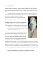
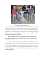
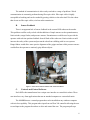
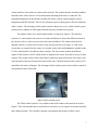
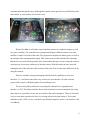
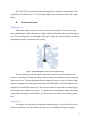
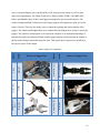
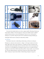
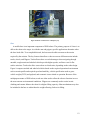
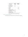
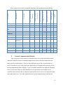
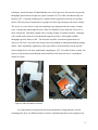
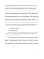
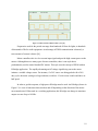
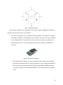
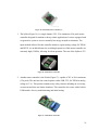
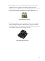
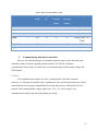
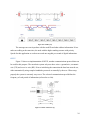
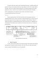
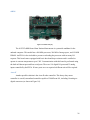
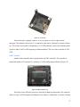
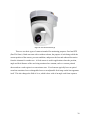
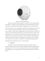
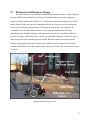
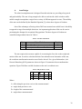
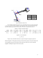
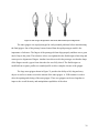
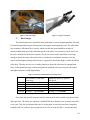
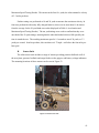
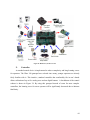
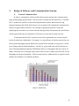
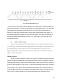
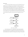
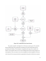
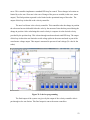
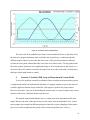
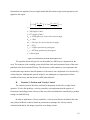
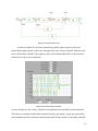
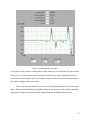
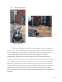
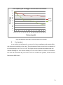
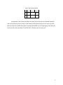
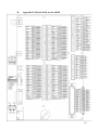
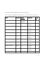
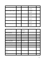
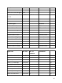
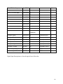

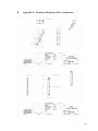
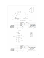

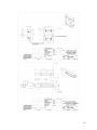
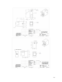

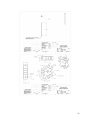
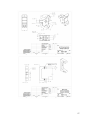
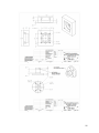

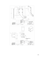
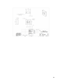


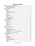
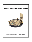
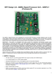

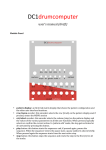
![000 CASORT [9].book](http://vs1.manualzilla.com/store/data/005753997_1-6c1117a0f29b8b2731a0aa33cfc5a43b-150x150.png)