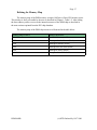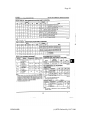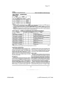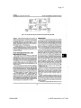
1
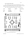
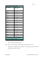
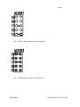
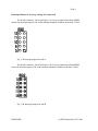
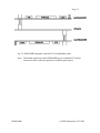
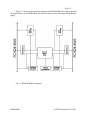
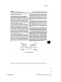
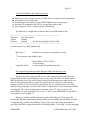
DPM104HR Dual Port SRAM
Interface Board
User's Manual
Real Time Devices Finland Oy
HARDWARE RELEASE 2.1
Real Time Devices Finland Oy
Lepolantie 14
FIN-00660 Helsinki, Finland
Tel: (+358) 9 346 4538
Fax: (+358) 9 346 4539
Email: [email protected]
URL: www.rtdfinland.fi
DPM104HR
(c) RTD Finland Oy 1997-2001
IMPORTANT
Although the information contained in this manual
has been carefully verified, RTD Finland Oy assumes
no responsibility for errors that might appear in
this manual, or for any damage to things or persons
resulting from improper use of this manual or from
the related software. RTD Finland Oy reserves the
right to change the contents of this manual, as
well as the features and specifications of this
product at any time, without notice.
Published by
Real Time Devices Finland Oy
Lepolantie 14
FIN-00660 Helsinki, Finland
Copyright © 1997-2001 by RTD Finland Oy
All rights reserved
Printed in Finland
DPM104HR
(c) RTD Finland Oy 1997-2001
Table of Contents
Page
===============================================================
INTRODUCTION
Dual Port Memory
Mechanical description
Connector description
What comes with your board
Board accessories
Application software and drivers
Hardware accessories
Using this manual
When you need help
CHAPTER 1 - BOARD SETTINGS
Factory configured jumper settings
Base address jumpers
Interrupt channels
CHAPTER 2 - BOARD INSTALLATION
Board installation
CHAPTER 3 - HARDWARE DESCRIPTION
Dual Port Memory
Interrupts
Semaphores
Backup Battery connection
CHAPTER 4 - BOARD OPERATION AND PROGRAMMING
Defining the memory map
DPM datasheet reprint from IDT
Interrupts
What is an interrupt?
Interrupt request lines
8259 Programmable interrupt controller
Interrupt mask register (IMR)
End-Of-Interrupt (EOI) Command
What exactly happens when an interrupt occurs?
Using interrupts in your program
Writing an interrupt service routine (ISR)
Saving the startup IMR and interrupt vector
Common Interrupt mistakes
APPENDIX A - DPM104HR Specifications
DPM104HR
(c) RTD Finland Oy 1997-2001
List of Illustrations
Page
===============================================================
To be completed later
DPM104HR
(c) RTD Finland Oy 1997-2001
Page 1
INTRODUCTION
===============================================================
DPM104HR
(c) RTD Finland Oy 1997-2001
Page 2
This user's manual describes the operation of the DPM104HR Dual Port Memory interface board.
Some of the key properties of the DPM104HR include:
8K x 16 True Dual Ported memory cells with simultaneous
reads from the same memory location
Mapped into 18KB of host low memory
On-chip arbitration logic
Full on-chip hardware and software for semaphore signalling
between ports
Full asyncronous operation from either port
Interrupts from both sides
Backup with external battery and power supply supervisor
+5V only operation
-40 to +85C Operating temperature range
PC/104 compliant
The following paragraphs briefly describe the major features of the DPM104HR. A more
detailed discussion is included in Chapter 3 (Hardware description) and in Chapter 4 (Board
operation and programming. The board setup is described in Chapter 1 (Board Settings). A
full description of the Dual Port Memory chip is included in Chapter 4.
Dual Port Memory
The DPM104HR dual port memory interface is implemented using monolithic memory
chip. This chip provides a high speed low power asyncronous acess to a total of 16 KB of RAM
memory. Inter-port arbitratration is integrated into the chip. To enable high speed data t ransfers
hardware semaphores and interrupts are supported.
To maintain memory contents in cases of power loss an external battery may be used
to provide power for the memory.
Mechanical description
The DPM104HR is designed on a PC/104 form factor. An easy mechanical interface to
PC/104 systems can be achieved. Stack two PC/104 compliant cpuModules directly on your
DPM104HR using the onboard mounting holes.
Connector description
There are two 16-bit PC/104 bus connectors on the DPM104HR to directly interface to
two cpuModules with 16-bit busses. One connector on the top side of the board is the Master
side of the DPM and the other connector on the bottom of the board is the Slave side.
DPM104HR
(c) RTD Finland Oy 1997-2001
Page 3
Note! Only 16-bit CPU bus boards may be used with the DPM104HR.
What comes with your board
You receive the following items in your DPM104HR package:
* DPM104HR Dual Port Memory interface module
* User's manual
Note: DOS/WIN95/98/2000/NT 4.0 drivers and test software
are available from our website at www.rtdfinland.fi.
If any item is missing or damaged, please call Real Time Devices Finland customer service
department at (+358) 9 346 4538.
Board accessories
In addition to the items included in your DPM104HR delivery several software and
hardware accessories are available. Call your distributor for more information on these accessories
and for help in choosing the best items to support your distributed control system.
Using this manual
This manual is intended to help you install your new DPM104HR card and get it
running quickly, while also providing enough detail about the board and it's functions so
that you can enjoy maximum use of it's features even in the most demanding applications.
When you need help
This manual and all the example programs will provide you with enough information to
fully utilize all the features on this board. If you have any problems installing or using this board,
contact our Technical Support Department (+358) 9 346 4538 during European business hours,
or send a FAX to (+358) 9 346 4539 or Email to [email protected]. When sending a FAX or
Email request, please include your company's name and address, your name, your telephone
number, and a brief description of the problem.
DPM104HR
(c) RTD Finland Oy 1997-2001
Page 4
CHAPTER 1 - BOARD SETTINGS
===============================================================
The DPM104HR board has jumper settings you can change to suit your application
and host computer memory configuration. The factory settings are listed and shown in
the diagram in the beginning of this chapter.
DPM104HR
(c) RTD Finland Oy 1997-2001
Page 5
Factory configured Jumper Settings
Table 1-1 illustrates the factory jumper setting for the DPM104HR. Figure 1-1 shows
the board layout of the DPM104HR and the locations of the jumpers. The following paragraphs
explain how to change the factory jumper settings to suit your specific application.
Table 1-1 Factory configured jumper settings see figure 1-1 for detailed locations
JUMPER
NAME
DESCRIPTION
OF JUMPER
NUMBER OF
JUMPERS
FACTORY SETTING
JUMPERS INSTALLED
ADDR_A
ADDR_B
IRQ_A
IRQ_B
BASE ADDRESS
BASE ADDRESS
HOST INTERRUPT
HOST INTERRUPT
5
5
5
5
D8000
D8000
Not connected
Not connected
Fig. 1-1 - Board layout showing jumper locations
DPM104HR
(c) RTD Finland Oy 1997-2001
Page 6
Base Address Jumpers
(Factory setting: D8000h)
The DPM104HR is memory mapped into the low memory of your host computer. The
board occupies a memory window of 18KB starting from the base address.
The most common cause of failure when you are first setting up your module is address
contention. Some of your computers memory space is already occupied by other devices and
memory resident programs. When the DPM104HR attempts to use it's reserved memory
addresses already used by another device, erratic performance may occur and data read from
the board may be corrupted.
To avoid this problem make sure you set up the base address first using the 5 jumpers
marked "ADDR" which let you choose from number of addresses in your host computers
memory map. Should the factory installed setting of D8000h be unusable for your system
configuration, you may change this setting to another using the options illustrated in Table 1-2
and in Figures 1-2 and 1-3 . The table shows the jumper settings and their corresponding values
in hexadecimal values. Make sure you verify the correct location of the base address jumpers.
When the jumper is removed it corresponds to a logical "1", connecting the jumper to a "0".
When you set the base address of the module, record the setting in the table inside the back
cover of this manual after the Appendices.
Note: If you are using a memory manager such as QEMM, make sure you exclude the
memory section you are occupying by the DPM104HR; for example X=D000-D8FF.
DPM104HR
(c) RTD Finland Oy 1997-2001
Page 7
Address Settings for DPM104HR
Base Address
Hex
Jumper Settings
18 17 16 1
80XXX
0 0 0 0
88XXX
0 0 0 1
90XXX
0 0 1 0
98XXX
0 0 1 1
A0XXX
0 1 0 0
A8XXX
0 1 0 1
B0XXX
0 1 1 0
B8XXX
0 1 1 1
C0XXX
1 0 0 0
C8XXX
1 0 0 1
D0XXX
1 0 1 0
D8XXX
1 0 1 1
E0XXX
1 1 0 0
E8XXX
1 1 0 1
F0XXX
1 1 1 0
F8XXX
1 1 1 1
1 = NO JUMPER, 0 = JUMPER installed
Note : A19 is always decoded as 1 !
Table 1-2 Base address jumper settings
Note: The above table illustrates only the settings for the address bits A18-A15.
Address line A19 should always be decoded as "1" since low memory area 00000 -7ffff
is normally occupied by the system.
DPM104HR
(c) RTD Finland Oy 1997-2001
Page 8
Fig. 1-2 Base address jumpers for side A (Master)
Fig. 1-3 Base address jumpers for side B (Slave)
DPM104HR
(c) RTD Finland Oy 1997-2001
Page 9
Interrupt Channel A (Factory setting: Not connected)
The header connector, shown on Figure 1-4a, lets you connect the onboard DPM
master side interrupt output to one of the interrupt channels available on the host AT bus.
Fig. 1-4a Interrupt jumpers for side A
The header connector, shown on Figure 1-4b, lets you connect the onboard DPM
slave side interrupt output to one of the interrupt channels available on the host AT bus.
Fig. 1-4b Interrupt jumpers for side B
DPM104HR
(c) RTD Finland Oy 1997-2001
Page 10
CHAPTER 2 - BOARD INSTALLATION
===============================================================
The DPM104HR memory interface board is very easy to connect to your industrial
distributed control system. Direct interface two PC/104 computers in one stack! This
chapter tells you step-by-step how to install your DPM104HR into your system.
DPM104HR
(c) RTD Finland Oy 1997-2001
Page 11
Board Installation
Keep your board in its antistatic bag until you are ready to install it to your system!
When removing it from the bag, hold the board at the edges and do not touch the components
or connectors. Please handle the board in an antistatic environment and use a grounded
workbench for testing and handling of your hardware.
Before installing the board in your computer, check the jumper settings. Chapter 1
reviews the factory settings and how to change them. If you need to change any settings,
refer to the appropriate instructions in Chapter 1. Note that incompatible jumper settings
can result in unpredictable board operation and erratic response.
General installation guidelines:
1. Turn OFF the power to your computer and all devices connected to DPM104HR
2. Touch the grounded metal housing of your computer to discharge any
antistatic buildup and then remove the board from its antistatic bag.
3. Hold the board by it's edges and install it in an enclosure or place it on the
table on an antistatic surface.
4. Connect the board to the two PC/104 cpuModules using the two bus interface
connectors.
Installation integrated with a PC/104 module stack:
* Secure the two PC/104 installation holes opposite to the bus connectors
with standoffs.
* Connect the DPM104HR board to the two PC/104 cpuModules using the two
bus interface connectors.
DPM104HR
(c) RTD Finland Oy 1997-2001
Page 12
Fig. 2-1 DPM104HR integrated with two PC/104 cpuModule stacks
Note: The default connectors on the DPM104HR are two soldertail PC/104 bus
connectors. Other connector options are available upon request.
DPM104HR
(c) RTD Finland Oy 1997-2001
Page 13
CHAPTER 3 - HARDWARE DESCRIPTION
===============================================================
Chapter 3 - Hardware Description describes the major features of the DPM104HR:
the Dual Port Memory chip, Interrupts , Semaphores and Backup battery supply.
DPM104HR
(c) RTD Finland Oy 1997-2001
Page 14
Figure 3-1 shows the general block diagram of the DPM104HR. This chapter describes
the major features of the DPM104HR: the Dual Port Memory chip, Interrupts and the Battery
supply.
Fig. 3-1 DPM104HR Block diagram
DPM104HR
(c) RTD Finland Oy 1997-2001
Page 15
Dual Port Memory chip
The onboard memory is a 8K x 16 Dual port static RAM. The device provides two
independent ports with separate control, access and I/O pins that permit independent,
asyncronous access for reads and writes to any location in the memory. Automatic
powerdown in activated when the chip is not addressed. Interrupts and semaphores are
supported, the onchip busy flag is not used.
Interrupts
If you wish to use the interrupt supported by the Dual port memory chips, a memory
mailbox is assigned to each port. The Slave port interrupt flag is set when the Master port
writes to memory location FFE (hex). The Slave port clears the interrupt by reading the same
address. Likewise for the Master writing to address FFF (hex). The messages at addresses
FFE and FFF (hex) are user definable. Refer to component specific datasheet for more detailed
information on the functionality of interrupts.
Semaphores
The Dual port RAM chip has eight locations dedicated to binary semaphore flags.
These flags allow the CPU on the Slave or Master side to claim a priviledge over the other
CPU for functions defined by the system software. As an example, the semaphore can be used
by one CPU to inhibit the other CPU from accessing blocks of memory or shared resources.
Software handshaking between CPU's offers the maximum in system flexibility by
permitting shared resources to be allocated in various system configurations. The DPM chip
does not use the semaphore to control any resources through hardware, thus allowing the
system designer maximum flexibility. Refer to component specific datasheet for more
detailed information on how to use semaphores.
Battery supply
The DPM104HR board has an onboard power supply supervisor to monitor the RAM
supply voltage. A small 10 micro Farad charge capacitor will provide enough power for small
transient power losses. This capacitor is kept in charge while power is maintained normally.
For completely non volatile operation an external 3,6V battery must be used in header connector
X1 located next to the Master 16-bit PC/104 bus connector. The polarity of the battery is
important, see picture below for correct connection of the external battery.
Pin 1 - GND (square pad)
Pin 2 - 3,6V battery power
DPM104HR
(c) RTD Finland Oy 1997-2001
Page 16
CHAPTER 4 - BOARD OPERATION AND PROGRAMMING
===============================================================
This chapter shows you how to program and use your DPM104HR. It provides a
complete detailed description of the memory map and a detailed discussion of programming
operations to aid you in programming. The full functionality of the Dual Port Memory chip
is described in the datasheet reprint from IDT. You may use the diagnostics and software
supplied by RTD to fully test your system under different operating systems. Please download
the latest drivers and software form our website: <www.rtdfinland.fi>.
DPM104HR
(c) RTD Finland Oy 1997-2001
Page 17
Defining the Memory Map
The memory map of the DPM memory occupies 18 Kbytes of host CPU memory space.
This window is freely selectable by the user as described in Chapter 1, Table 1-2. After setting
the base address you have access to the internal resources of the DPM-chip as described in
the next sections reprinted from the IDT chip datasheet.
The memory map of the DPM chip resources is illustrated in the table below.
Address Range in HEX
Memory Resources
000-1FFE
Dual Port Memory mailbox area
1FFE
Interrupt clear for Master (Read)
1FFE
Interrupt to Master (Write)
1FFF
Interrupt clear for Slave (Read)
1FFF
Interrupt to Slave (Write)
2000-2008
Semaphore bits for both sides
DPM104HR
(c) RTD Finland Oy 1997-2001
Page 18
DPM104HR
(c) RTD Finland Oy 1997-2001
Page 19
DPM104HR
(c) RTD Finland Oy 1997-2001
Page 20
DPM104HR
(c) RTD Finland Oy 1997-2001
Page 21
DPM104HR
(c) RTD Finland Oy 1997-2001
Page 22
DPM104HR
(c) RTD Finland Oy 1997-2001
Page 23
DPM104HR
(c) RTD Finland Oy 1997-2001
Page 24
DPM104HR
(c) RTD Finland Oy 1997-2001
Page 25
DPM104HR
(c) RTD Finland Oy 1997-2001
Page 26
Interrupts
- What is an interrupt ?
An interrupt is an event that causes the processor in your computer to temporarily halt
its current process and execute another routine. Upon completion of the new routine, control is
returned to the original routine at the point where its execution was interrupted.
Interrupts are a very flexible way of dealing with asynchronous events. Keyboard activity
is a good example; your computer cannot predict when you might press a key and it would be a
waste of processor time to do nothing while waiting for a keystroke to occur. Thus the interrupt
scheme is used and the processor proceeds with other tasks. Then when a keystroke occurs,
the keyboard 'interrupts' the processor , and the processor gets the keyboard data, placed it into
memory, and then returns to what it was doing before the interrupt occurred. Other common
devices that use interrupts are network boards, A/D boards, serial ports etc.
You can interrupt the other processor on the other side of the DPM by writing to the
topmost addresses of the memory at addresses 1FFE and 1FFF. When an interrupt is received
you may signal that data has been updated in the memory. By using interrupts you can write
powerful code to interface to your DPM104HR.
-Interrupt request lines
To allow different peripheral devices to generate interrupts on the same computer, the
PC AT bus has interrupt request channels (IRQ's). A rising edge transition on one of these lines
will be latched into the interrupt controller. The interrupt controller checks to see if the interrupts
are to be acknowledged from that IRQ and, if another interrupt is being processed, it decides if
the new request should supersede the one in progress or if it has to wait until the one in progress
is done. The priority level of the interrupt is determined by the number of the IRQ; IRQ0 has the
highest priority IRQ15 the lowest. Many of the IRQ's are used by the standard system resources.
IRQ0 is dedicated for the internal timer, IRQ1 is dedicated to the keyboard input, IRQ3 for serial
port COM2 and IRQ4 for serial port COM1. Often interrupts 3,5 and 7 are free for the user.
- 8259 Programmable Interrupt Controller
The chip responsible for handling interrupt requests in a PC is the 8259 Interrupt
Controller. To use interrupts you will need to know how to read and set the 8259's internal
interrupt mask register (IMR) and how to send the end-of-interrupt (EOI) command to
acknowledge the 8259 interrupt controller.
DPM104HR
(c) RTD Finland Oy 1997-2001
Page 27
-Interrupt Mask Register (IMR)
Each bit in the interrupt mask register (IMR) contains the mask status of the interrupt
line. If a bit is set (equal to 1), then the corresponding IRQ is masked, and it will not generate
an interrupt. If a bit is cleared (equal to 0), then the corresponding IRQ is not masked, and it
can generate an interrupt. The interrupt mask register is programmed through port 21h.
-End-of-Interrupt (EOI) Command
After an interrupt service routine is complete, the 8259 Interrupt Controller must be
acknowledged by writing the value 20h to port 20h.
-What exactly happens when an interrupt occurs?
Understanding the sequence of events when an interrupt is triggered is necessary to
correctly write interrupt handlers. When an interrupt request line is driven high by a peripheral
device (such as the ECAN527), the interrupt controller checks to see if interrupts are enabled
for that IRQ, and then checks to see if other interrupts are active or requested and determines
which interrupt has priority. The interrupt controller then interrupts the processor. The current
code segment (CS), instruction pointer (IP), and flags are pushed onto the system stack., and a
new set if CS and IP are loaded from the lowest 1024 bytes of memory.
This table is referred to as the interrupt vector table and each entry to this table is called an
interrupt vector. Once the new CS and IP are loaded from the interrupt vector table, the
processor starts to execute code from the new Code Segment (CS) and from the new
Instruction Pointer (IP). When the interrupt routine is completed the old CS and IP are popped
from the system stack and the program execution continues from the point it was interrupted.
-Using Interrupt in your Program
Adding interrupt support to your program is not as difficult as it may seem especially
when programming under DOS. The following discussion will cover programming under DOS.
Note, that even the smallest mistake in your interrupt program may cause the computer to hang
up and will only restart after a reboot. This can be frustrating and time-consuming.
-Writing an Interrupt Service Routine (ISR)
The first step in adding interrupts to your software is to write an interrupt service routine
(ISR). This is the routine that will be executed automatically each time an interrupt request occurs
for the specified IRQ. An ISR is different from other subroutines or procedures. First, on entrance
the processor registers must be pushed onto the stack before anything else! Second, just before
exiting the routine, you must clear the interrupt on the DPM104HR and write the EOI command
to the interrupt controller. Finally, when exiting the interrupt routine the processor registers must
DPM104HR
(c) RTD Finland Oy 1997-2001
Page 28
be popped from the system stack and you must execute the IRET assembly instruction. This
instruction pops the CS, IP and processor flags from the system stack. These were pushed
onto the stack when entering the ISR:
Most compilers allow you to identify a function as an interrupt type and will automatically
add these instructions to your ISR with one exception: most compilers do not automatically add
the EOI command to the function, you must do it yourself. Other than this and a few exceptions
discussed below, you can write your ISR as any code routine. It can call other functions and
procedures in your program and it can access global data. If you are writing your first ISR, we
recommend you stick to the basics; just something that enables you to verify you have entered
the ISR and executed it successfully. For example: set a flag in your ISR and in your main
program check for the flag.
Note: If you choose to write your ISR in in-line Assembly , you must push and pop
registers correctly, and exit the routine with the IRET instruction instead of the RET instruction.
There are a few precautions you must consider when writing ISR's. The most important
is, do not use any DOS functions or functions that call DOS functions from an interrupt
routine. DOS is not reentrant; that is, a DOS function cannot call itself. In typical programming,
this will not happen because of the way DOS is written. But what about using interrupts? Then,
you could have the situation such as this in your program. If DOS function X is being executed
when an interrupt occurs and the interrupt routine makes a call to the DOS function X, then
function X is essentially being called while active. Such cases will cause the computer to crash.
DOS does not support such operation. A general rule is , that do not call any functions that use
the screen, read keyboard input and any file I/O routines should not be used in ISR's.
The same problem of reentrancy exists for many floating point emulators as well, meaning
you should avoid floating point mathematical operations in your ISR.
Note, that the problem of reentrancy exists, no matter what programming language
you use. Even, if you are writing your ISR in Assembly language, DOS and many floating
point emulators are not reentrant. Of course, there are ways to avoid this problem, such as
those which involve checking if any DOS functions are currently active when your ISR is
called, but such solutions are beyond the scope of this manual.
The second major concern when writing ISR's is to make them as short as possible in
term of execution time. Spending long times in interrupt service routines may mean that other
important interrupts are not serviced. Also, if you spend too long in your ISR, it may be called
again before you have exited. This will lead to your computer hanging up and will require
a reboot.
DPM104HR
(c) RTD Finland Oy 1997-2001
Page 29
Your ISR should have the following structure:
Push any processor registers used in your ISR. Most C compiler do this automatically
Put the body of your routine here
Read interrupt status address of your DPM104HR board to clear interrupt
Issue the EOI command to the 8259 by writing 20h to address 20h
Pop all registers. Most C compilers do this automatically
The following C example shows what the shell of your ISR should be like:
/*------------------------------------------------------------------------------| Function:
new_IRQ_handler
| Inputs:
Nothing
| Returns:
Nothing
- Sets the interrupt flag for the EVENT.
|-------------------------------------------------------------------------------*/
void interrupt far new_IRQ_handler(void)
{
IRQ_flag = 1;
// Indicate to main process interrupt has occurred
{
// Your program code should be here
}
// Read address 1FFE or 1FFF to
// Clear interrupt
outp(0x20, 0x20);
/* Acknowledge the interrupt controller. */
}
-Saving the Startup Interrupt Mask Register (IMR) and interrupt vector
The next step after writing the ISR is to save the startup state of the interrupt mask
register (IMR) and the original interrupt vector you are using. The IMR is located in address
21h. The interrupt vector you will be using is located in the interrupt vector table which is an
array of 4-byte pointers (addresses) and it is located in the first 1024 bytes of the memory
(Segment 0 offset 0). You can read this value directly, but it is a better practice to use DOS
function 35h (get interrupt vector) to do this. Most C compilers have a special function available
for doing this. The vectors for the hardware interrupts on the XT - bus are vectors 8-15,
where IRQ0 uses vector 8 and IRQ7 uses vector 15. Thus if your DPM104HR is using IRQ5 it
corresponds to vector number 13.
Before you install your ISR, temporarily mask out the IRQ you will be using. This
prevents the IRQ from requesting an interrupt while you are installing and initializing your ISR.
To mask the IRQ, read the current IMR at I/O port 21h, and set the bit that corresponds to
your IRQ. The IMR is arranged so that bit 0 is for IRQ0 and bit 7 is for IRQ7. See the paragraph
DPM104HR
(c) RTD Finland Oy 1997-2001
Page 30
entitled Interrupt Mask Register (IMR) earlier in this discussion for help in determining your
IRQ's bit. After setting the bit, write the new value to I/O port 21h.
With the startup IMR saved and the interrupts temporarily disabled, you can assign the
interrupt vector to point to your ISR. Again you can overwrite the appropriate entry in the
vector table with a direct memory write, but this is not recommended. Instead use the DOS
function 25h (Set Interrupt Vector) or, if your compiler provides it, the library routine for
setting up interrupt vectors. Remember , that interrupt vector 8 corresponds to IRQ0, vector
9 for IRQ1 etc.
If you need to program the source of your interrupts, do that next. For example, if
you are using transmitted or received messages as an interrupt source , program it to do that.
Finally, clear the mask bit for your IRQ in the IMR. This will enable your IRQ.
-Common Interrupt mistakes
Remember, hardware interrupts are from 8-15, XT IRQ's are numbered 0-7
Forgetting to clear the IRQ mask bit in the IMR
Forgetting to send the EOI command after ISR code. Disables further interrupts.
Example on Interrupt vector table setup in C-code:
void far _interrupt new_IRQ1_handler(void );
#define IRQ1_VECTOR
3
void (interrupt far *old_IRQ1_dispatcher)
(es,ds,di,si,bp,sp,bx,dx,cx,ax,ip,cs,flags);
void far _interrupt new_IRQ1_handler(void );
/* ISR function prototype */
/* Name for IRQ */
/* Variable to store old IRQ_Vector */
/*---------------------------------------------------------------------| Function:
init_irq_handlers
| Inputs:
Nothing
| Returns:
Nothing
| Purpose:
Set the pointers in the interrupt table to point to
|
our funtions ie. setup for ISR's.
|----------------------------------------------------------------------*/
void init_irq_handlers(void)
{
_disable();
old_IRQ1_handler = _dos_getvect(IRQ1_VECTOR + 8);
_dos_setvect(IRQ1_VECTOR + 8, new_IRQ1_handler);
Gi_old_mask = inp(0x21);
outp(0x21,Gi_old_mask & ~(1 << IRQ1_VECTOR));
_enable();
}
DPM104HR
(c) RTD Finland Oy 1997-2001
Page 31
|/*---------------------------------------------------------------------| Function:
restore do this before exiting program
| Inputs:
Nothing
| Returns:
Nothing
| Purpose:
Restore interrupt vector table.
|----------------------------------------------------------------------*/
void restore(void)
{
/* Restore the old vectors */
_disable();
_dos_setvect(IRQ1_VECTOR + 8, old_IRQ1_handler);
outp(0x21,Gi_old_mask);
_enable();
}
DPM104HR
(c) RTD Finland Oy 1997-2001
Page 32
APPENDIX A
====================================================================
DPM104HR Specifications
Host Interface
Memory mapped into low memory
Jumper-selectable base address
16-bit data bus
Jumper selectable interrupts XT and AT
16Kbytes
Connectors
Host bus (Master / Slave side)
16-bit PC/104 busses
Electrical
Operating temperature range
Supply voltage
Power consumption
DPM104HR
-40 to +85C
+5V only
1,25W
(c) RTD Finland Oy 1997-2001
Page 33
NOTES:
(C) RTD Finland Oy 1997-2001 DOC: DPM104HR.SAM
DPM104HR
(c) RTD Finland Oy 1997-2001