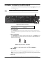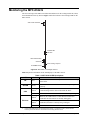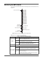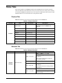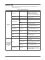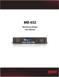
1
MFC-8322-S and MFC-OG3-N OG3 Network Controller Cards User Manual Thank you for choosing Ross You've made a great choice. We expect you will be very happy with your purchase of Ross Technology. Our mission is to: 1. Provide a Superior Customer Experience • offer the best product quality and support 2. Make Cool Practical Technology • develop great products that customers love Ross has become well known for the Ross Video Code of Ethics. It guides our interactions and empowers our employees. I hope you enjoy reading it below. If anything at all with your Ross experience does not live up to your expectations be sure to reach out to us at [email protected]. David Ross CEO, Ross Video [email protected] Ross Video Code of Ethics Any company is the sum total of the people that make things happen. At Ross, our employees are a special group. Our employees truly care about doing a great job and delivering a high quality customer experience every day. This code of ethics hangs on the wall of all Ross Video locations to guide our behavior: 1. We will always act in our customers’ best interest. 2. We will do our best to understand our customers’ requirements. 3. We will not ship crap. 4. We will be great to work with. 5. We will do something extra for our customers, as an apology, when something big goes wrong and it's our fault. 6. We will keep our promises. 7. We will treat the competition with respect. 8. We will cooperate with and help other friendly companies. 9. We will go above and beyond in times of crisis. If there's no one to authorize the required action in times of company or customer crisis - do what you know in your heart is right. (You may rent helicopters if necessary.) MFC-8322-S and MFC-OG3-N User Manual • Ross Part Number: 8322DR-004-01 • Release Date: February 26, 2014. Copyright © 2014 Ross Video Limited. Ross®, openGear®, and any related marks are trademarks or registered trademarks of Ross Video Ltd. All other trademarks are the property of their respective companies. PATENTS ISSUED and PENDING. All rights reserved. No part of this publication may be reproduced, stored in a retrieval system, or transmitted in any form or by any means, mechanical, photocopying, recording or otherwise, without the prior written permission of Ross Video. While every precaution has been taken in the preparation of this document, Ross Video assumes no responsibility for errors or omissions. Neither is any liability assumed for damages resulting from the use of the information contained herein. Patents Patent numbers 4,205,346; 5,115,314; 5,280,346; 5,561,404; 7,034,886; 7,508,455; 7,602,446; 7,834,886; 7,914,332; 8,499,019 B2; 2039277; 1237518; 1127289 and other patents pending. Important Regulatory and Safety Notices to Service Personnel Before using this product and any associated equipment, refer to the “Important Safety Instructions” listed below to avoid personnel injury and to prevent product damage. Product may require specific equipment, and/or installation procedures to be carried out to satisfy certain regulatory compliance requirements. Notices have been included in this publication to call attention to these specific requirements. Symbol Meanings This symbol on the equipment refers you to important operating and maintenance (servicing) instructions within the Product Manual Documentation. Failure to heed this information may present a major risk of damage to persons or equipment. Warning — The symbol with the word “Warning” within the equipment manual indicates a potentially hazardous situation, which, if not avoided, could result in death or serious injury. Caution — The symbol with the word “Caution” within the equipment manual indicates a potentially hazardous situation, which, if not avoided, may result in minor or moderate injury. It may also be used to alert against unsafe practices. Notice — The symbol with the word “Notice” within the equipment manual indicates a potentially hazardous situation, which, if not avoided, may result in major or minor equipment damage or a situation which could place the equipment in a non-compliant operating state. ESD Susceptibility — This symbol is used to alert the user that an electrical or electronic device or assembly is susceptible to damage from an ESD event. Important Safety Instructions Caution — This product is intended to be a component product of the openGear frame. Refer to the OG3-FR Series Frame User Manual for important safety instructions regarding the proper installation and safe operation of the frame as well as its component products. Warning — Certain parts of this equipment namely the power supply area still present a safety hazard, with the power switch in the OFF position. To avoid electrical shock, disconnect all A/C power cords from the chassis’ rear appliance connectors before servicing this area. Warning — Service barriers within this product are intended to protect the operator and service personnel from hazardous voltages. For continued safety, replace all barriers after any servicing. This product contains safety critical parts, which if incorrectly replaced may present a risk of fire or electrical shock. Components contained with the product’s power supplies and power supply area, are not intended to be customer serviced and should be returned to the factory for repair. To reduce the risk of fire, replacements fuses must be the same time and rating. Only use attachments/accessories specified by the manufacturer. EMC Notices United States of America FCC Part 15 This equipment has been tested and found to comply with the limits for a class A Digital device, pursuant to part 15 of the FCC Rules. These limits are designed to provide reasonable protection against harmful interference when the equipment is operated in a commercial environment. This equipment generates, uses, and can radiate radio frequency energy and, if not installed and used in accordance with the instruction manual, may cause harmful interference to radio communications. Operation of this equipment in a residential area is likely to cause harmful interference in which case the user will be required to correct the interference at their own expense. Notice — Changes or modifications to this equipment not expressly approved by Ross Video Limited could void the user’s authority to operate this equipment. CANADA This Class “A” digital apparatus complies with Canadian ICES-003. Cet appariel numerique de la classe “A” est conforme a la norme NMB-003 du Canada. EUROPE This equipment is in compliance with the essential requirements and other relevant provisions of CE Directive 93/68/EEC. INTERNATIONAL This equipment has been tested to CISPR 22:1997 along with amendments A1:2000 and A2:2002, and found to comply with the limits for a Class A Digital device. Notice — This is a Class A product. In domestic environments, this product may cause radio interference, in which case the user may have to take adequate measures. Maintenance/User Serviceable Parts Routine maintenance to this openGear product is not required. This product contains no user serviceable parts. If the module does not appear to be working properly, please contact Technical Support using the numbers listed under the “Contact Us” section on the last page of this manual. All openGear products are covered by a generous 5-year warranty and will be repaired without charge for materials or labor within this period. See the “Warranty and Repair Policy” section in this manual for details. Environmental Information The equipment that you purchased required the extraction and use of natural resources for its production. It may contain hazardous substances that could impact health and the environment. To avoid the potential release of those substances into the environment and to diminish the need for the extraction of natural resources, Ross Video encourages you to use the appropriate take-back systems. These systems will reuse or recycle most of the materials from your end-of-life equipment in an environmentally friendly and health conscious manner. The crossed out wheelie bin symbol invites you to use these systems. If you need more information on the collection, re-use, and recycling systems, please contact your local or regional waste administration. You can also contact Ross Video for more information on the environmental performance of our products. Company Address Ross Video Limited Ross Video Incorporated 8 John Street P.O. Box 880 Iroquois, Ontario, K0E 1K0 Ogdensburg, New York Canada USA 13669-0880 General Business Office: (+1) 613 • 652 • 4886 Fax: (+1) 613 • 652 • 4425 Technical Support: (+1) 613 • 652 • 4886 After Hours Emergency: (+1) 613 • 349 • 0006 E-mail (Technical Support): [email protected] E-mail (General Information): [email protected] Website: http://www.rossvideo.com Contents Introduction 1 Features ................................................................................................................................ 1-2 User Interfaces ..................................................................................................................... 1-3 DashBoard Control System ................................................................................... 1-3 Card-edge Controls................................................................................................ 1-3 SNMP Monitoring and Control ............................................................................. 1-3 Documentation Terms and Conventions.............................................................................. 1-4 Installation 2 Before You Begin ................................................................................................................ 2-2 Related Publications .............................................................................................. 2-2 Installing a Network Controller Card .................................................................................. 2-3 To install a Network Controller Card.................................................................... 2-3 Network Configuration ........................................................................................................ 2-4 Automatic Configuration using DHCP ................................................................. 2-4 Preset Configuration using DIP Switches ............................................................. 2-5 Custom User Configuration via DashBoard.......................................................... 2-6 User Rights Management ...................................................................................... 2-6 Using a Master Password..................................................................................................... 2-7 Before You Begin.................................................................................................. 2-7 Configuring the Master Password ......................................................................... 2-7 Accessing a Network Controller Card................................................................... 2-8 Enabling SNMP Support ..................................................................................................... 2-9 Enabling SNMP Support ....................................................................................... 2-9 Configuring the SNMP Agent using DashBoard .................................................. 2-9 Software Upgrades............................................................................................................. 2-11 MFC-8322-S Setup 3 Card-edge Controls for the MFC-8322-S ............................................................................ 3-2 Configuring the DIP Switches ............................................................................................. 3-3 Monitoring the MFC-8322-S ............................................................................................... 3-4 MFC-OG3-N Series Setup 4 Card-edge Controls for the MFC-OG3-N............................................................................ 4-2 Configuring the DIP Switches ............................................................................................. 4-3 Monitoring the MFC-OG3-N............................................................................................... 4-4 Ethernet Switch Monitoring .................................................................................. 4-5 SNMP Monitoring on the MFC-OG3-NS ............................................................. 4-5 DataSafe 5 Overview.............................................................................................................................. 5-2 DataSafe and MFC-OG3-N ................................................................................................. 5-3 Using the Alarm Button ........................................................................................ 5-3 Enabling DataSafe ................................................................................................. 5-3 MFC-8322-S and MFC-OG3-N User Manual (Iss. 01) Contents • i Re-naming a Card Slot........................................................................................... 5-3 Hiding the DataSafe Warnings .............................................................................. 5-3 Forcing DataSafe Files to Load ............................................................................. 5-4 Resetting an MFC-OG3-N to Factory Defaults..................................................... 5-4 DashBoard Menus 6 Status Tabs ........................................................................................................................... 6-2 Product Tab............................................................................................................ 6-2 Network Tab .......................................................................................................... 6-2 Hardware Tab ........................................................................................................ 6-4 Power Tab .............................................................................................................. 6-5 Setup Tab ............................................................................................................................. 6-7 Restoring Menu Items to Factory Default Settings ............................................... 6-8 Network Tab......................................................................................................................... 6-9 DataSafe Tab ...................................................................................................................... 6-10 SNMP Tab.......................................................................................................................... 6-11 Notes on the Trap/Notification Target Feature.................................................... 6-11 DashBoard Lite Applet 7 Before You Begin ................................................................................................................ 7-2 System Requirements ............................................................................................ 7-2 To run the DashBoard Lite Applet ........................................................................ 7-2 DashBoard Lite Applet Overview........................................................................................ 7-3 Interface Overview ................................................................................................ 7-3 Device View .......................................................................................................... 7-4 Adding Frames to the DashBoard Lite Applet..................................................................... 7-5 To add frames to the DashBoard Lite applet ......................................................... 7-5 Using the DashBoard Lite Applet ........................................................................................ 7-6 Password Protected Frames ................................................................................... 7-6 To change and verify device information for the MFC-OG3-N............................ 7-6 Uploading Software to a Card.............................................................................................. 7-7 Troubleshooting ................................................................................................................... 7-8 Starting the DashBoard Lite Applet ...................................................................... 7-8 Device Tab Issues .................................................................................................. 7-8 Frame Connections ................................................................................................ 7-8 Troubleshooting the Software Upload Process...................................................... 7-9 Service Information 8 Troubleshooting Checklist ................................................................................................... 8-2 MFC-8322-S Alarm Mute/Bootload Button.......................................................... 8-2 MFC-OG3-N.......................................................................................................... 8-2 Warranty and Repair Policy ................................................................................................. 8-4 Index ii • Contents IX MFC-8322-S and MFC-OG3-N User Manual (Iss. 01) Introduction In This Chapter This chapter contains the following sections: • Features • User Interfaces • Documentation Terms and Conventions A Word of Thanks Congratulations on choosing an openGear Network Controller Card. Your Network Controller Card is part of a full line of products within the openGear Terminal Equipment family of products, backed by Ross Video’s experience in engineering and design expertise since 1974. You will be pleased at how easily your new card fits into your overall working environment. Equally pleasing is the product quality, reliability and functionality. Thank you for joining the group of worldwide satisfied Ross Video customers! Should you have a question pertaining to the installation or operation of your card, please contact us at the numbers listed on the back cover of this manual. Our technical support staff is always available for consultation, training, or service. MFC-8322-S and MFC-OG3-N User Manual (Iss. 01) Introduction • 1–1 Features The MFC-8322-S and MFC-OG3-N are designed for the OG3-FR frames and offer a range of monitoring and control options based on the card model. Table 1.1 outlines the features.. Table 1.1 Feature Comparison Chart MFC-OG3Series Model Features 8322-S OG3-N OG3-NS Compatible with the DFR-8310 series frames Compatible with the DFR-8321 series frames Compatible with the OG3-FR series frames Monitors frame power usage, the inlet ambient temperature, the airflow requirements of high-powered cards, and sets the fan speed accordinglya Monitors the frame door and each frame power supply Monitors the fan door and notifies the user if the door is left open too long Monitors the status of other cards in the frame via the internal bus Supports the DataSafe feature in DashBoard Generates alarms if any of the monitored functions develop errors Network settingsb storage location On the GFC-8322 Reference card Provides SNMP Monitoring Provides external 10/100Mbps ethernet connectivity to communicate with DashBoard Provides external 1000Mbps ethernet connectivity to communicate with DashBoard Provides internal 1000BASE-X Ethernet links to all 20 slots for high speed communication between cards Supports more than one concurrent TCP Control connections, such as DashBoard, or a control panel 5-year transferable warranty a. b. Higher power consumption requires higher fan speed for adequate cooling. The fans always run at maximum speed for 5 seconds after the fan door is closed, then adjust to the appropriate level based on power consumption and the inlet ambient temperature. Saves items configured on the Network tab plus the Frame Name. 1–2 • Introduction MFC-8322-S and MFC-OG3-N User Manual (Iss. 01) User Interfaces Your Network Controller Card may include the following interfaces. DashBoard Control System The DashBoard Control System enables you to monitor and control openGear frames and cards from a computer. DashBoard communicates with other cards in the openGear frames through the Network Controller Cards. The DashBoard software and user manual are available for download from our website. For More Information on... • installing and using DashBoard, refer to the DashBoard User Manual. • the available menus in DashBoard for your card, refer to the chapter “DashBoard Menus” on page 6-1. Card-edge Controls The front-edge of the Network Controller Card feature LED indicators for the power, ethernet connection, and general communication activity. The Network Controller Card also include DIP switches for specifying the IP address of the frame. For More Information on... • the specific front-edge controls, refer to the applicable chapter in this manual. SNMP Monitoring and Control The Network Controller Card can provide optional support for remote monitoring of your openGear frame and using the Simple Network Management Protocol (SNMP). This protocol is compatible with many third-party monitoring and control tools. For More Information on... • SNMP monitoring and control, refer to the section “Enabling SNMP Support” on page 2-9. • SNMP controls for your openGear card, refer to the Management Information Base (MIB) file for your card. MFC-8322-S and MFC-OG3-N User Manual (Iss. 01) Introduction • 1–3 Documentation Terms and Conventions This section outlines the terms and conventions used throughout this manual. Terms The following terms are used: • “Board”, and “Card” refer to openGear terminal devices within openGear frames, including all components and switches. • “DashBoard” refers to the DashBoard Control System. • “Network Controller Card” refers to the MFC-8322-S, MFC-OG3-N, and MFC-OG3-NS unless otherwise noted. • “MFC-OG3-N” refers to MFC-OG3-N and MFC-OG3-NS unless otherwise noted. • “OG3-FR series frames” refers to all versions of the OG3-FR series frames unless otherwise noted. • “openGear frame” refers to the OG3-FR series frames. • “Operator” and “User” refer to the person who uses the Network Controller Card. • “System” and “Video system” refer to the mix of interconnected production and terminal equipment in your environment. Conventions The following conventions are used: • 1–4 • Introduction “Operating Tips” and “Note” boxes are used throughout this manual to provide additional user information. MFC-8322-S and MFC-OG3-N User Manual (Iss. 01) Installation In This Chapter This chapter provides instructions for installing the Network Controller Card, configuring the network settings, and enabling the SNMP monitoring option. The following topics are discussed: • Before You Begin • Installing a Network Controller Card • Network Configuration • Using a Master Password • Enabling SNMP Support • Software Upgrades MFC-8322-S and MFC-OG3-N User Manual (Iss. 01) Installation • 2–1 Before You Begin Before you begin, ensure to read the following sections. Static Discharge Throughout this chapter, please heed the following cautionary note: ESD Susceptibility — Static discharge can cause serious damage to sensitive semiconductor devices. Avoid handling circuit boards in high static environments such as carpeted areas and when synthetic fiber clothing is worn. Always exercise proper grounding precautions when working on circuit boards and related equipment. Unpacking Unpack each Network Controller Card you received from the shipping container. If any items are missing or damaged, contact your sales representative or Ross Video directly. Related Publications It is recommended to consult the following Ross Video documentation before installing and configuring your Network Controller Card: 2–2 • Installation • DashBoard User Manual, Ross Part Number: 8351DR-004 • OG3-FR Series User Manual, Ross Part Number: 8322DR-005 MFC-8322-S and MFC-OG3-N User Manual (Iss. 01) Installing a Network Controller Card This section outlines how to install an Network Controller Card in an openGear frame. The same procedure applies regardless of the frame or card type. The Network Controller Card installs in the last slot on the right side of the openGear frame (when facing the frame). Caution — You must install the MFC-8322-S and the MFC-OG3-N into an OG3-FR series frame. Attempting to install these cards in another frame type can damage your card. To install a Network Controller Card 1. Power off the openGear frame. 2. Open the frame door. 3. If necessary, remove any cards from the frame that would interfere with easy access and lines of sight. 4. Lift the lock before inserting the card into its slot. (Figure 2.1) Lift to unlock Figure 2.1 MFC-OG3 Series Card — Lock 5. Insert the Network Controller Card, with the component side out into the card guides between the dividing wall and the last slot, ensuring the card does not touch the Card Retaining Screw. 6. Slide the card in the slot until firmly seated. 7. Ensure the lock on the front edge of the card is engaged in the down position. 8. Power up the frame. 9. Close the frame door. 10. Check the operation of the fans. If the fans do not operate, verify that: • the Network Controller Card is seated properly in the frame backplane. • the Network Controller Card is aligned to the Fan PCB when the door is closed. MFC-8322-S and MFC-OG3-N User Manual (Iss. 01) Installation • 2–3 Network Configuration The Network Controller Card features an ethernet interface which allows cards in the openGear frame to be monitored and controlled using the DashBoard Control System. Communication is possible only when the Network Controller Card is suitably configured to match the network to which it is connected. Note — Consult your IT Department before configuring any network settings. This section explains the necessary parameters and lists several possible methods for managing these parameters. • Automatic configuration using DHCP — When shipped from the factory, the Network Controller card is configured to automatically obtain network settings from a Dynamic Host Configuration Protocol (DHCP) server. Since most networks have a DHCP server available, this method is applicable to most users and is the recommended method. • Preset configuration using DIP switch(es) — The Network Controller card can be forced to use specific pre-defined network settings by means of DIP switches located on the card surface. This can be used to establish initial communications when no DHCP server is available, or to override a custom user configuration. • Custom user configuration via DashBoard — Using the network setting options available in the DashBoard Control System, you may configure the Network Controller card to use a static address or enable DHCP for automatic configuration. This can only be done once communication has been established. Important — Before proceeding, ensure that the DashBoard Control System software is installed on your computer. Automatic Configuration using DHCP This method assumes that the Network Controller Card is using the factory default values for the network settings. Note — The Network Controller Card boots much faster than a typical DHCP server. In the case of a facility-wide power failure, the Network Controller card may not appear on the network if communications with the DHCP server cannot be established. Once the DHCP server becomes operational, re-boot the Network Controller Card to re-establish communications. To avoid this, you may use a static configuration as described in the section “Custom User Configuration via DashBoard” on page 2-6. To establish communications 1. Ensure that openGear frame is connected to the same network as your DashBoard computer. 2. Launch the DashBoard application on your computer. 3. Power on the openGear frame that the Network Controller card is installed in. 4. Wait approximately 30 seconds while the frame establishes network communications. 5. Verify that the Network Controller Card displays in the Tree View of DashBoard. 2–4 • Installation MFC-8322-S and MFC-OG3-N User Manual (Iss. 01) 6. Should the card fail to display after two minutes: • Verify the ethernet cables are properly connected. • Check the link/activity LEDs found on the ethernet RJ-45 connectors. • Ensure the network settings for the Network Controller card are set to the factory default values. • If all cables are connected and the LEDs do not indicate an error, then automatic configuration is not possible. Proceed to the section “Preset Configuration using DIP Switches” on page 2-5. Preset Configuration using DIP Switches This method is used to established initial communications when no DHCP server is available, or to override a custom user configuration and is intended to be used temporarily in order to establish communication. Once initial communications are established, the Network Controller card should be configured for either DHCP or Static operation. Note — Use of this method for normal operation is not recommended, as there is a high chance of IP Address conflicts. To use a preset network configuration using the DIP Switch(es) 1. Power down the openGear frame that houses the Network Controller card. 2. Quit DashBoard on your computer. 3. Set the DIP Switch to specify the preset IP Address as outlined in the applicable Setup chapter of this manual for your Network Controller card model. 4. Ensure the network settings of your computer are compatible with those chosen for the Network Controller card. Note — The IP Addresses of the Network Controller Card and your computer must be similar, but not identical, and the Subnet Mask must match exactly the same. For example, if the Network Controller card has an IP Address of 192.168.2.1, then your computer should be configured for an IP Address with 192.168.2.X where X is a number other than 1. 5. Before you begin, and to prevent IP Address conflicts, isolate the Network Controller Card and your DashBoard computer from the rest of your network. • If you are using a hub or switch, unplug all devices except the Network Controller Card and your DashBoard computer; or • Connect the openGear frame directly to the DashBoard computer. Note — The MFC-8322-S, and MFC-OG3-N, support Auto-MDIX, enabling you to use any ethernet cable when connecting the frame to the DashBoard computer. 6. Launch DashBoard on your computer. 7. Power up the openGear frame. 8. Wait approximately 30 seconds while the frame establishes network communications. 9. Verify that the Network Controller Card displays in the Tree View of DashBoard. 10. Should the card fail to display after a minute or two: • Verify the ethernet cables are properly connected. MFC-8322-S and MFC-OG3-N User Manual (Iss. 01) Installation • 2–5 • Check the link/activity LEDs found on the ethernet RJ-45 connectors. • Verify that you have properly performed each step of this procedure. • Contact Ross Video Technical Support if you cannot establish a connection. Custom User Configuration via DashBoard Once communication has been establish with the Network Controller Card, the network settings may be further adjusted using the following procedure. Note that the steps are optional, you may perform as many, or as few, as needed. Operating Tip — Some settings may require that you configure a DIP Switch before proceeding. Refer to the chapter “MFC-8322-S Setup” on page 3-1, or “MFC-OG3-N Series Setup” on page 4-1 for details. To configure the network settings via DashBoard 1. In DashBoard, display the Device tab of the Network Controller Card by double-clicking its status indicator in the Basic Tree View. 2. From the Device tab, select the Network tab. 3. To change the display name of the frame, enter a new name in the Frame Name field. 4. To change the Network Time Server address, enter the new IP Address in the NTP Server field. 5. To change between Static and DHCP addressing, select an option in the Addressing Mode area. 6. Configure the network settings as required: • IP Address — This is the IP Address of the Network Controller Card. • Subnet Mask — This is the Subnet Mask address for your LAN. • Default Gateway — This is the IP Address for connection outside the subnet. 7. To save the new settings, click Apply in the Network tab. The settings are saved immediately and take effect except when overridden by DIP Switch settings. Clicking Cancel reverts to the previous settings. User Rights Management If your facility has installed and configured the DashBoard Server and URM feature, you may need to enter a URM user name and password to access the frame and any of the devices installed in the frame. For details on configuring and using the DashBoard Server and URM feature, refer to the DashBoard Server and URM User Manual. 2–6 • Installation MFC-8322-S and MFC-OG3-N User Manual (Iss. 01) Using a Master Password Right-clicking an openGear frame node in the tree view of DashBoard provides the option to Lock/Unlock Access which requires the user to enter a Master Password before gaining access to the frame and the cards installed in it. This Master Password can be the same for all frames listed in the DashBoard client, or unique to each frame, or a mix. When using the DashBoard Server and URM, openGear frame nodes in the Tree View display a lock icon to inform the user that restrictions are in place. This lock icon indicates that the node is locked and requires a Master Password, or that the user must log into the DashBoard client with a valid user account, to gain access to the node. For More Information on... • the lock icon, refer to the DashBoard Server and URM User Manual. Before You Begin Refer to Table 2.1 to verify that you are running the required DashBoard and card software versions. Note that at time of writing, the current version of DashBoard is 6.0. Table 2.1 Required Software Versions Card Model DashBoard Version Card Software Version MFC-8322-S 4.0.0 or higher 2.00 or higher MFC-OG3-N 4.0.0 or higher 2.75 or higher Configuring the Master Password Configuring the Master Password for your frame requires configuring the password feature in DashBoard. Setting the DIP Switch Your Network Controller Card includes SW3 (a DIP Switch) that enables you to override the Master Password. Use this DIP switch when the Master Password needs to be reset (e.g. when you have forgotten the password text). If you change the configuration of the DIP Switch, you must reboot the card before the changes take effect. Override the Master Password using the DIP Switch as follows: • OFF — This is the recommended position. A user-specified Master Password is used.The default password is password. It can be changed using DashBoard as outlined in the section “To configure the Master Password in DashBoard” on page 2-7. • ON — This position is used to recover a lost Master Password. The user-specified password is temporarily ignored, and the default value of password is used. To configure the Master Password in DashBoard 1. Navigate to the frame in the Tree View of the DashBoard client. 2. Right-click the frame node and select Lock/Unlock Access to display the Change Master Password dialog. By default, the current Master Password for the frame is automatically entered into the Old Password field. 3. Select the Change master password check box. MFC-8322-S and MFC-OG3-N User Manual (Iss. 01) Installation • 2–7 4. Type the new Master Password for the frame in the New Password field. 5. Re-type the new Master Password for the frame in the Confirm field. 6. Select the Prevent unauthorized access to this frame check box to enforce access controls for this frame. • Users with older version of DashBoard will be unable to connect to the frame. • DashBoard clients version 4.0.0 or higher will use DashBoard URM to determine user access rights. 7. From the dialog window located under the Confirm field, select the frame(s) you wish to apply the new Master Password to. Or you can use the provided menu to quickly select all frames, clear the selections, select only presently locked frames, or select only currently unlocked frames. 8. Click OK. Accessing a Network Controller Card You can access a Network Controller Card using your user account, assuming you have permissions to do so. If DashBoard URM is implemented in your facility and your DashBoard client is version 4.0.0 or higher, you log in as outlined in the procedure “To use a valid user account”. If DashBoard URM is unavailable, or when using the DashBoard Lite applet, you log in as outlined in the procedure “To use the Master Password”. To use a valid user account 1. Launch the DashBoard client on your computer. 2. Log into the DashBoard client with your user account and password. 3. Navigate to the frame in the Tree View of the DashBoard client. To use the Master Password 1. Launch the DashBoard client on your computer. 2. Navigate to a locked frame displayed in the Tree View of the DashBoard client. 3. Double-click the frame node to display the Password Required dialog. You can also double-click the frame name and select Open. 4. Enter the Master Password for the frame in the provided field. 5. Select one of the following methods: • Click Try Password to connect to the selected frame; or • Click Try for All to connect to all locked frames displayed in the Tree View. Only when you attempt to connect to additional locked frames and the login fails, are you prompted for the password. 6. If the password was incorrect, an error message displays to prompt you for another log in attempt. 2–8 • Installation MFC-8322-S and MFC-OG3-N User Manual (Iss. 01) Enabling SNMP Support Certain versions of the MFC-OG3-N provides optional support for remote monitoring and control of your frame and openGear cards using SNMP (Simple Network Management Protocol), which is compatible with many third-party monitoring and control tools. Refer to the section “Features” on page 1-2 for a list of cards that support SNMP. Note — The MFC-8322-S does not support SNMP. Enabling SNMP Support The SNMP monitoring and control feature for your MFC-OG3-N is a software option that is field upgradable using DashBoard. Note — If SNMP is enabled on an MFC-OG3-N, it will perform as an MFC-OG3-NS although DashBoard and SNMP still display MFC-OG3-N. To enable SNMP support using the SNMP tab in DashBoard 1. Ensure that you have configured the network settings for your card as outlined in the section “Network Configuration” on page 2-4. 2. In DashBoard, display the Device tab of the card by double-clicking its status indicator in the Basic Tree View. 3. From the Device tab, select the Setup tab. 4. In the Licensable Features area, make a note of the information displayed in the SNMP Request Code field. 5. Contact Ross Video Technical Support. • When you speak to the Technical Support representative, tell them your name, your facility name, and the SNMP Request Code displayed in the Setup tab. • You will be given a License Key that must be entered in the SNMP Feature Key field of the Setup tab. 6. Enter the License Key in the SNMP Feature Key field. 7. When the installation is complete, verify that the Setup tab displays “Licensed” in the SNMP Feature field and that the SNMP tab is now available in the Device View. Configuring the SNMP Agent using DashBoard The SNMP agent on the frame will accept SNMP GET and SET requests on the default SNMP port (161), using SNMP version 1 or SNMP version 2c. The SNMP Agent will send SNMP traps to one or more notification targets, with user-configurable address, port, and protocol version number. To configure your SNMP Agent via DashBoard 1. In DashBoard, display the Device tab of the card by double-clicking its status indicator in the Basic Tree View. 2. From the Device tab, select the SNMP tab. MFC-8322-S and MFC-OG3-N User Manual (Iss. 01) Installation • 2–9 3. Set the required parameters as follows: • Read Community String — Enter the SNMP password for GET requests. For example, public. • Write Community String — Enter the SNMP password for SET requests. For example, private. 4. To add a trap/notification target, edit the Trap/Notification Target field. This field follows the format of ##.#.#.##/aaa;bb;cc where: • ##.#.#.## represents the Target IP address to which traps should be sent. • aaa represents the UDP Port number to which traps should be sent. • bb represents the SNMP protocol version to be used for traps to this target. • cc represents the Target community string. An example is provided in the SNMP tab in DashBoard. 5. Click Add to update the list with the new target. 6. Click Apply to apply your changes or Cancel to discard the changes. To remove a trap/notification target, select the target in the list, and click Delete. 2–10 • Installation MFC-8322-S and MFC-OG3-N User Manual (Iss. 01) Software Upgrades Your Network Controller Card can be upgraded in the field from DashBoard (via TCP/IP) or using the DashBoard Lite applet. For More Information on... • using the DashBoard Lite applet, refer to the section “Uploading Software to a Card” on page 7-7. To upgrade the software on a Network Controller Card 1. Contact Ross Technical Support for the latest software version file. 2. In DashBoard, display the Device tab of the Network Controller Card by double-clicking its status indicator in the Basic Tree View. 3. From the Device tab, click Upload to display the Select file for upload dialog. 4. Navigate to the *.bin upload file you want to upload to the Network Controller Card. 5. Click Open to display a confirmation dialog. 6. If you are upgrading a single card, click Finish to display the Uploading to Selected Devices dialog. Proceed to step 8. 7. If you are upgrading multiple cards: • Click Next > to display the Select Destination menu. This menu provides a list of the compatible cards based on the card selected in step 2. • Specify the card(s) to upload the file to by selecting the check box(es) for the cards you wish to upload the file to. • Verify that the card(s) you wish to upload the file to. The Error/Warning fields indicate any errors, such as incompatible software or card type mismatch. • Click Finish to display the Uploading to Selected Devices dialog. • Proceed to step 8. 8. Monitor the upgrade. • The Uploading to Selected Devices dialog enables you to monitor the upgrade process. • Notice that each card is listed in the dialog with a button. This button is replaced with a Reboot button once the software file is loaded to that card. Important — Avoid clicking the individual Reboot buttons until all cards have successfully completed the file upload process and the OK button, located in the bottom right corner of the dialog, is enabled. • Click OK to reboot all the cards listed in the Uploading to Selected Devices dialog. • The Reboot Confirm dialog displays, indicating the number of cards that will reboot. Click Yes to continue the upgrade process. Note that clicking Cancel or No returns you to the Uploading to Selected Devices dialog without rebooting the card(s). Note — The communications processor of the Network Controller Card requires approximately 30 seconds to re-start and re-establish network communications. MFC-8322-S and MFC-OG3-N User Manual (Iss. 01) Installation • 2–11 • The card(s) are temporarily taken offline during the reboot process. The process is complete once the status indicators for the Card State and Connection return to their previous status. Troubleshooting If you encounter problems when upgrading your card software, verify the following: • Your network settings on the card are valid. • The ethernet cable is properly connected if you are uploading the file via a network connection. • The file you are attempting to load is a *.bin file that is for the card you are upgrading. Note — If the MFC-OG3-N fails to upgrade correctly, contact Ross Technical Support for an upgrade file and instructions on using the Micro SD Card slot on your card. 2–12 • Installation MFC-8322-S and MFC-OG3-N User Manual (Iss. 01) MFC-8322-S Setup In This Chapter This chapter provides information on setting up and using the card-edge controls of the MFC-8322-S Controller Card. Caution — You must install the MFC-8322-S into an OG3-FR series frame. Attempting to install the MFC-8322-S in another frame type can damage your card. The following topics are discussed: • Card-edge Controls for the MFC-8322-S • Configuring the DIP Switches • Monitoring the MFC-8322-S MFC-8322-S and MFC-OG3-N User Manual (Iss. 01) MFC-8322-S Setup • 3–1 Card-edge Controls for the MFC-8322-S This section provides information on the jumpers, buttons and LEDs for the MFC-8322-S. Refer to Figure 3.1 for the location of card control features such as the Alarm Mute button, and the Alarm Config jumpers. Note — The MFC-8322-S provides a single DashBoard connection. Figure 3.1 MFC-8322-S Card Controls 1) Alarm Mute Button 3) DIP Switches 2) Alarm Config Jumper 4) Card Lock 1. Alarm Mute Button The Alarm Mute button on the card-edge of the MFC-8322-S mutes the audio alarm for two minutes. If a fault condition is still present when the mute time-out ends, the card re-activates the audio alarm. 2. Alarm Config Jumper The Alarm Config jumper enables or disables the audio alarm signal. The ALARM LED is still lit if alarm conditions are occurring, but the audio will be off. Refer to Figure 3.2 and the card labeling for jumper positions. 1 1 2 2 3 3 Pin Position 1+2 Pin Position 2+3 Figure 3.2 Alarm Config Jumper — Pin Positions • Enabled — To enable the alarm feature, set the jumper into Position 1+2. • Disabled — To disable the alarm feature, set the jumper into Position 2+3. 3. DIP Switches SW1 and SW2 are used in conjunction with the DashBoard menus to set the IP Address of the MFC-8322-S. Refer to the section “Configuring the DIP Switches” on page 3-3 for details. SW3 is used to override the Master Password for the MFC-8322-S. This password limits access to the card, and the cards installed in the frame. 4. Card Lock This lock located near the front edge of the card is used to secure the card in its frame slot. 3–2 • MFC-8322-S Setup MFC-8322-S and MFC-OG3-N User Manual (Iss. 01) Configuring the DIP Switches This section briefly summarizes the DIP Switch settings on the MFC-8322-S. Figure 3.3 shows the DIP Switches in the ON position. O N 1 2 3 4 Figure 3.3 DIP Switches — Set to the ON Positions SW1, SW2 — IP Address Setup SW1 and SW2 are used in conjunction with the DashBoard menus to set the IP Address of the MFC-8322-S. Refer to Table 3.1 for DIP Switch positions. For information on configuring the network settings for your card, refer to the section “Network Configuration” on page 2-4. Table 3.1 SW1 and SW2 Positions SW1 Position SW2 Position Controlled via DashBoard OFF OFF OFF ON The card network settings are automatically assigned (DHCP Mode). ON OFF The card IP Address is set to 192.168.2.1 The card Subnet Mask is set to 255.255.255.0. ON ON The card IP Address is set to 10.1.2.1. The card Subnet Mask is set to 255.255.255.0. a. Descriptions The card network settings can be set by the user from the DashBoard Network taba. (default) DHCP Mode is assumed until the user changes the settings in DashBoard. SW3 — Master Password Override SW3 is used to override the Master Password. This feature forces a reset of the Master Password. Refer to the section “Using a Master Password” on page 2-7 for details. • OFF — This is the recommended position. A user-specified Master Password is used. The default password is password. It can be changed using DashBoard as outlined in the section “Using a Master Password” on page 2-7. • ON — This position is used to recover a lost Master Password. The user-specified password is temporarily ignored, and the default value of password is used. SW4 SW4 is not implemented at this time and should be left in the OFF position. MFC-8322-S and MFC-OG3-N User Manual (Iss. 01) MFC-8322-S Setup • 3–3 Monitoring the MFC-8322-S The front card-edge of the MFC-8322-S has LED indicators for the cooling module fan, alarm, and communication activity. Refer to Figure 3.4 for the location of the card-edge LEDs on the MFC-8322-S. SW1-4 DIP Switches ALARM LED OK LED Alarm Mute Button CAN LED Alarm Config Jumpers ETHERNET LED Figure 3.4 MFC-8322-S Card-edge Controls Table 3.2 provides information on the LED displays of the MFC-8322-S. Table 3.2 MFC-8322-S LED Descriptions LED OK ALARM CAN Ethernet a. 3–4 • MFC-8322-S Setup Color Description Red When lit, this LED indicates a major alarm condition is occurring in the frame. Green When lit, this LED indicates the MFC-8322-S is operating correctly. Flashing Yellow When flashing, this LED indicates the MFC-8322-S is communicating with the other cards within the frame. Off When off, this LED indicates an absence of incoming messages. Yellowa When lit, this LED indicates a valid ethernet link has been established. No data transfer is currently taking place. Flashing Yellow When flashing, this LED indicates that a valid link has been established, and data is currently being exchanged. Off When off, this LED indicates an absence of ethernet connection. If this LED remains lit for an extended period of time (e.g. minutes or more), ensure that the Ethernet port on the frame is connected to a functioning ethernet switch. MFC-8322-S and MFC-OG3-N User Manual (Iss. 01) MFC-OG3-N Series Setup In This Chapter This chapter provides information on setting up and using the card-edge controls of the MFC-OG3-N and MFC-OG3-NS Controller Cards. The MFC-OG3-N and MFC-OG3-NS bring GigE ethernet connectivity to the OG3-FR frames infrastructure, providing a DashBoard interface to monitor openGear cards in the frame. The MFC-OG3-NS includes the SNMP Monitoring option. Caution — You must install the MFC-OG3-N and MFC-OG3-NS into an OG3-FR series frame. Attempting to install the MFC-OG3-N or MFC-OG3-NS in another frame type can damage your card. The following topics are discussed: • Card-edge Controls for the MFC-OG3-N • Configuring the DIP Switches • Monitoring the MFC-OG3-N MFC-8322-S and MFC-OG3-N User Manual (Iss. 01) MFC-OG3-N Series Setup • 4–1 Card-edge Controls for the MFC-OG3-N This section provides information on the jumpers, buttons and LEDs for the MFC-OG3-N and MFC-OG3-NS. Refer to Figure 4.1 for the location of the card-edge features. Figure 4.1 MFC-OG3-N — Card Control Locations 1) Alarm Mute Button 3) DIP Switches 2) Alarm Config Jumper 4) Card Lock 5) Micro SD Card Slot 1. Alarm Mute Button The Alarm Mute button on the card-edge mutes the audio alarm for two minutes. If a fault condition is still present when the mute time-out ends, the card re-activates the audio alarm. Pressing and holding this button, while powering on the frame or installing the card, will enable emergency booting as described in the section “MFC-OG3-N” on page 8-2. 2. Alarm Config Jumper The Alarm Config jumper enables or disables the audio alarm signal. The ALARM LED is still lit if alarm conditions are occurring, but the audio will be off. Refer to Figure 4.2 and the card labeling for jumper positions. 1 1 2 2 3 Pin Position 1+2 3 Pin Position 2+3 Figure 4.2 Alarm Config Jumper — Pin Positions • Enabled — To enable the alarm feature, set the jumper into Position 1+2. • Disabled — To disable the alarm feature, set the jumper into Position 2+3. 3. DIP Switches SW1 and SW2 are used in conjunction with the DashBoard menus to set the IP Address of the card. Refer to the section “SW1, SW2 — IP Address Setup” on page 4-3 for details. SW3 is used to override the Master Password for the frame. Refer to the section “SW3 — Master Password Override” on page 4-3 for details. 4. Card Lock This lock located near the front edge of the card is used to secure the card in its frame slot. 5. Micro SD Card Slot This slot is used in the case of a software upgrade failure and under the guidance of Ross Technical Support. This slot is not populated with an SD Card when shipped from the factory. 4–2 • MFC-OG3-N Series Setup MFC-8322-S and MFC-OG3-N User Manual (Iss. 01) Configuring the DIP Switches This section briefly summarizes the DIP Switch settings on the card. Refer to Figure 4.1 for the locations. Note that Figure 4.3 shows the DIP Switches in the ON position. O N 1 2 3 4 Figure 4.3 DIP Switches — Set to the ON Positions SW1, SW2 — IP Address Setup SW1 and SW2 are used in conjunction with the DashBoard menus to set the IP Address of the card. Refer to Table 4.1 and the card labeling for DIP Switch positions. For more information on configuring the network settings for your card, refer to the section “Network Configuration” on page 2-4. Table 4.1 SW1 and SW2 Positions SW1 Position SW2 Position Controlled via DashBoard OFF OFF OFF ON The card network settings are automatically assigned (DHCP Mode). ON OFF The card IP Address is set to 192.168.2.1 The card Subnet Mask is set to 255.255.255.0. ON ON The card IP Address is set to 10.1.2.1. The card Subnet Mask is set to 255.255.255.0. a. Descriptions The card network settings can be set by the user from the DashBoard Network taba. (default) DHCP Mode is assumed until the user changes the settings in DashBoard. SW3 — Master Password Override SW3 is used to override the Master Password. The Master Password feature limits the card to support only authenticated connections. Refer to the section “Using a Master Password” on page 2-7 for details. • OFF — This is the recommended position. A user-specified Master Password is used. The default password is password. It can be changed using DashBoard as outlined in the section “Using a Master Password” on page 2-7. • ON — This position is used to recover a lost Master Password. The user-specified password is temporarily ignored, and the default value of password is used. SW4 SW4 is not implemented at this time and should be left in the OFF position. MFC-8322-S and MFC-OG3-N User Manual (Iss. 01) MFC-OG3-N Series Setup • 4–3 Monitoring the MFC-OG3-N The front-edge of the card has LED indicators for indicating alarms, and communication activity. (Figure 4.4) SW1-4 DIP Switches RJ45 LED CPU 0 LED CPU 1 LED Alarm Mute Button Slot 1 LED Slot 2 LED Slot 3 LED Slot 4 LED Slot 5 LED Slot 6 LED Slot 7 LED Slot 8 LED Slot 9 LED Slot 10 LED Slot 11 LED Slot 12 LED Slot 13 LED Slot 14 LED Slot 15 LED Slot 16 LED Slot 17 LED Slot 18 LED Slot 19 LED Slot 20 LED OK/ALARM LED PHY 1 LED PHY 2 LED Alarm Config Jumpers CAN LED ETHERNET LED Figure 4.4 MFC-OG3-N and MFC-OG3-NS Card-edge Controls Table 4.2 provides information on the LED displays. Table 4.2 MFC-OG3-N LED Descriptions LED Slot # RJ45 Color Yellow When lit, this LED indicates that the ethernet link to the specified frame slot is established (link is up). Flashing Yellow When flashing, this LED indicates the ethernet link is established, and communication is currently taking place. Off When off, this LED indicates that the ethernet link to the specified frame slot is unavailable (link is down). This LED reports the same information as the ETHERNET LED. Green When lit green, this LED indicates the card is operating correctly. Flashing Green When flashing, this LED indicates a DataSafe mismatch. OK/ALARMa When lit red, this LED indicates: Red 4–4 • MFC-OG3-N Series Setup Description • the card is booting, or • a major alarm condition is occurring in the frame such as the frame door has been left open too long. MFC-8322-S and MFC-OG3-N User Manual (Iss. 01) Table 4.2 MFC-OG3-N LED Descriptions LED Color CPU # Yellow When lit, this LED indicates that the ethernet link to the internal GigE switch is established (link is up). Flashing Yellow When lit, this LED indicates that communication activity is occurring on the internal GigE switch. Off When off, this LED indicates the ethernet link to the internal GigE switch is unavailable (link is down). PHY 1 This LED reports the same information as the CPU 1 LED. PHY 2 This LED reports the same information as the CPU 0 LED. CAN ETHERNET a. Description Flashing Yellow When flashing yellow, this LED indicates the card is communicating, over the CAN bus, with the other cards within the frame. Off When off, this LED indicates an absence of incoming messages. Yellow When lit yellow, this LED indicates a valid ethernet connection but is not receiving messages from DashBoard, a control panel, or an external SNMP agent. Flashing Yellow When flashing yellow, this LED indicates the card is communicating over the ethernet connection to DashBoard, a control panel, or an external SNMP agent. Off When off, this LED indicates an absence of ethernet connection. This LED reports the most severe condition. Ethernet Switch Monitoring The MFC-OG3-N provides monitoring of its internal 1000BASE-X Ethernet link via the Network setup tab in DashBoard. Each frame slot is monitored separately for loss of link, communication speed, and when a network loop is detected within the cards in the openGear frame. Note that when a loop is detected, the MFC-OG3-N automatically disables the internal port on the card in that slot until a loop is no longer detected. The MFC-OG3-N also reports the connection speed of the Ethernet port on the frame chassis. For More Information on... • whether your openGear card provides an internal link to the ethernet switch of the MFC-OG3-N, refer to the manual that accompanied your card. • ethernet switch status fields of the MFC-OG3-N, refer to the section “Network Tab” on page 6-9. SNMP Monitoring on the MFC-OG3-NS The MFC-OG3-NS provides optional support for remote monitoring and control of your frame and openGear cards using SNMP (Simple Network Management Protocol), which is compatible with many third-party monitoring and control tools. You must obtain a license key from your openGear sales representative to enable SNMP support. For More Information on... • enabling and configuring the SNMP Agent for your MFC-OG3-NS, refer to the section “Enabling SNMP Support” on page 2-9. MFC-8322-S and MFC-OG3-N User Manual (Iss. 01) MFC-OG3-N Series Setup • 4–5 4–6 • MFC-OG3-N Series Setup MFC-8322-S and MFC-OG3-N User Manual (Iss. 01) DataSafe In This Chapter DataSafe enables you to load and store card parameters automatically, or you can load from and store to a single file in DashBoard. This feature is available for frames using the MFC-OG3-N, and MFC-OG3-NS cards only. For more information on using the DataSafe feature in DashBoard, refer to your DashBoard Control System User Manual. Note — DashBoard version 2.3.0 or higher is required to access DataSafe features. The following topics are discussed: • Overview • DataSafe and MFC-OG3-N MFC-8322-S and MFC-OG3-N User Manual (Iss. 01) DataSafe • 5–1 Overview The following DataSafe features are available when using a MFC-OG3-N: • The MFC-OG3-N monitors all traffic going through it. On power-up, the MFC-OG3-N queries for all card information. • Changes to writable parameters of cards is noted and the current version of all parameters is stored. Parameter data is stored locally on the network card for every slot independently. • Parameter data can be saved in a single file. • DataSafe enables the user to send all the parameter data to a card slot or to every slot on the network that matches. • You can use a limited DashBoard view to update a subset of cards instead of the entire connected view. DashBoard sends the file to a specific network card and slot for use. Once received, it updates the card if the attached card matches the data sent. • DataSafe stores and recalls the parameters automatically with or without a network connection. • When a DataSafe mismatch occurs, there is an audible alarm from the card and a warning message is displayed in DashBoard. You can clear the alarm using an option in the Setup tab, or by using the card-edge controls. A DataSafe mismatch occurs when the software version or the card type does not match the saved data for that slot. • Note that DataSafe is disabled by default. For More Information on... 5–2 • DataSafe • the options available in the DataSafe tab, refer to the section “DataSafe Tab” on page 6-10. • enabling DataSafe for your MFC-OG3-N, refer to the section “Enabling DataSafe” on page 5-3. MFC-8322-S and MFC-OG3-N User Manual (Iss. 01) DataSafe and MFC-OG3-N This section briefly summarizes the DataSafe options available for the MFC-OG3-N. Using the Alarm Button An audible alarm indicates when a DataSafe mismatch occurs, such as when a card is installed that does not match the compatibility range of the DataSafe saved data. • Single pressing the Alarm button mutes the audible alarm, but does not mask the alarm displayed in DashBoard. For information on masking DataSafe mismatch warnings, refer to the section “Hiding the DataSafe Warnings” on page 5-3. • Holding the Alarm Mute button on the MFC-OG3-N down for approximately 5 seconds causes the new settings of all cards to be copied to the saved DataSafe slots. Enabling DataSafe All slot fields in the DataSafe tab of your MFC-OG3-N are set to Disable by default. The Disable feature prevents DashBoard from automatically recalling the card parameters for the specified slot. You may still monitor the status of the cards in those slots, and DashBoard still updates the slot information when a new card is installed or when a card is removed from the slot and replaced with another card. To enable DataSafe for a specific slot 1. From the Tree View in DashBoard, double-click the MFC-OG3-N to display a corresponding Device Tab in the Device View. 2. Select the DataSafe tab. 3. Locate the card slot(s) you wish to enable DataSafe for. 4. Clear the corresponding checkbox in the Disable column. Re-naming a Card Slot DashBoard enables you to re-name a card slot and have that name display in all Tree Views and the DataSafe tab window for the specific MFC-OG3-N. To re-name an openGear slot in the Tree View 1. From the Tree View in DashBoard, double-click the MFC-OG3-N to display a corresponding Device Tab in the Device View. 2. Select the Setup tab. 3. In the Card Slot Names section of the Setup tab, locate the slot you wish to re-name. 4. Enter the new name for the card slot in the text field provided. Hiding the DataSafe Warnings A DataSafe mismatch warning occurs in DashBoard when: • a card of the same type is installed that does not match the software of the card previously installed in that slot; or MFC-8322-S and MFC-OG3-N User Manual (Iss. 01) DataSafe • 5–3 • a card of a different type is installed in the slot. DashBoard includes a Mask Warning option in the DataSafe tab for each MFC-OG3-N. Enabling the Mask Warning option prevents error messages from displaying in the Data Safe State field of the Hardware tab. To hide DataSafe mismatch warnings in DashBoard 1. From the Tree View in DashBoard, double-click the MFC-OG3-N to display a corresponding Device Tab in the Device View. 2. Select the DataSafe tab. 3. Mask the DataSafe mismatch warnings as follows: • Checkbox cleared — DashBoard displays an error message in the Data Safe State field of the Hardware tab. Information is also displayed in the Conflict field of the DataSafe tab to alert the user that a software mismatch is occurring. This is the default setting. • Checkbox selected — This feature is disabled. DashBoard does not update the Data Safe State field of the Hardware tab, nor the Conflict field of the DataSafe tab. Forcing DataSafe Files to Load The Conflict field in the DataSafe tab indicates when a currently installed card has a card type or software incompatibility. • When there is a DataSafe mismatch on the slot, the Update Slot button is enabled for that slot. Click this button to replace the last saved parameters with the current card parameters. • Use the Force button in the DataSafe tab to force the currently saved DataSafe data to load to all cards with software mismatches and store the new information. Refer to the DashBoard Control System User Manual for details. Resetting an MFC-OG3-N to Factory Defaults Through DashBoard, you can reset the factory settings of the MFC-OG3-N using the Restore button in the Setup tab. Note that the frame name is unaffected. Important — Clicking the Restore button erases all DataSafe data for the MFC-OG3-N. Clicking the Restore button in the Setup tab of the MFC-OG3-N performs the following tasks in DashBoard: 5–4 • DataSafe • All values in the Setup tab of the MFC-OG3-N are reset to the factory defaults. • All Slot names are deleted. Slot name fields are blank and all DashBoard fields are updated with the default names. MFC-8322-S and MFC-OG3-N User Manual (Iss. 01) DashBoard Menus In This Chapter This chapter provides information the DashBoard menus available for the Network Controller Cards. Note that some of the available menus and options are dependent on the card you are using. Default values are indicated with an asterisk (*). The DashBoard Control System enables you to monitor and control openGear frames and cards from a computer. DashBoard communicates with other cards in the OG3-FR series frame through the Network Controller Cards. You can download the DashBoard software and manual from the Ross Video website. The following topics are discussed: • Status Tabs • Setup Tab • Network Tab • DataSafe Tab • SNMP Tab MFC-8322-S and MFC-OG3-N User Manual (Iss. 01) DashBoard Menus • 6–1 Status Tabs This section summarizes the Status tabs displayed in DashBoard for the Network Controller Cards. The indicators in the Status tabs can vary in severity from green (valid), yellow (caution), to red (alarm). DashBoard reports the most severe alarm for a single field. Alarm colors are noted within the tables as text set in brackets next to the parameter name. Product Tab Table 6.1 summarizes the read-only information displayed in the Product tab. Table 6.1 Product Tab Items Tab Title Product Item Parameters Description Frame Name Name as defined by the user in the Network tab. Refer to Table 6.7 on page 6-9. Frame S/N Indicates the Frame Serial Number Product Indicates the model number of the card Supplier Ross Video Ltd. Board Rev ## Indicates the hardware revision Board S/N ######### Indicates the card serial number MAC Address ##-##-##-##-##-## MAC Address for the card Software Rev #.## Indicates the card software version Firmware Rev # Indicates the card firmware revision Network Tab Table 6.2 summarizes the read-only information displayed in the Network tab. Table 6.2 Network Tab Items Tab Title Item Parameters Description SW1 and SW2 are set to OFF. DHCP - set by user The Addressing Mode is set to DHCP in DashBoard. The network automatically assigns the card ethernet settings. Current Settings Static - set by user Network Source Static - set by user SW1 and SW2 are set to OFF. The Addressing Mode is set to Static in DashBoard. User defines the ethernet settings from the Network tab. SW1 is set to OFF and SW2 is set to ON. DHCP - set by DIP 6–2 • DashBoard Menus Network automatically assigns the card ethernet settings. MFC-8322-S and MFC-OG3-N User Manual (Iss. 01) Table 6.2 Network Tab Items Tab Title Item Parameters Description SW1 is set to ON and SW2 is set to OFF. Factory Default 1 Network Source Factory Default 2 Current Settings IP Address of the card is set to 10.1.2.1. ##.#.###.### IP Address of the card Subnet Mask ###.###.#.# Subnet Mask for the card Default Gateway ##.#.#.# Card gateway NTP Server ##.#.#.# IP Address of the NTP server used as a time source Open No access restrictions; the Network Controller Cards accepts connections from all DashBoard clients Authenticated Only Access control enabled; only DashBoard clients version 4.0.0 or higher can connect. The user must be authenticated by the DashBoard Server and URM, or must know the Master Password of the Network Controller Cards. ******** Indicates that a user-specified password is set for the Network Controller Cards Overridden by DIP switch The user-specified password is overridden because the DIP Switcha is enabled. The Master Password is now overridden to the factory default value of password. Active Connections # Number of external control devices, such as DashBoard, connected via TCP to the frame Active Cards # Number of active cards within the frame Bus Load (%) # Communication traffic of the internal CAN Bus. A high value indicates a high amount of traffic Connection Management Master Password a. SW1 and SW2 are set to ON. IP Address Access Mode Internal Bus Status IP Address of the card is set to 192.168.2.1 This is SW3 on the card-edge. MFC-8322-S and MFC-OG3-N User Manual (Iss. 01) DashBoard Menus • 6–3 Hardware Tab Table 6.3 summarizes the read-only information displayed in the Hardware tab. Table 6.3 Hardware Tab Items Tab Title Item Parameters Description OK (Green) Running a backup code (Yellow)a Fan door open (Red) PSU fuse blown (Red) PSU fault (Red) Frame status Frame Power >350W (Red)c Indicates the status of the frame, frame power supplies, and/or cards in the frame PSU fan stalled (Red) Card Fault (Red) PSU AC missing (Red)b PSU power off (Red) Ref card missing (Red) Mid-Plane ID Hardware # Indicates the board issue Enabled Indicates that the Alarm Config jumper is set to enable audio alarms Disabled The Audio Alarm is disabled Voltage (mV) # Supply Voltage Current (mA) # Current consumption of the card Negative Rail (mV) # Indicates the negative voltage of the card # Indicates the fan speed of the frame x/y Current Speed (x) / Maximum Speed (y) Audio Alarm Fan Speed Fan Door Open Indicates the state of the fan door Closed Present (Green) Indicates the specified frame power supply is installed in the frame and the corresponding Notify on PSU Missing alarm is may or may not be enabled on the Setup tab. Not Present (Green) Indicates the specified frame power supply is not installed, but the corresponding Notify on PSU Missing alarm is disabled on the Setup tab. PSU# Statusc 6–4 • DashBoard Menus This alarm is set using the Fan Speed option in the Setup tab. MFC-8322-S and MFC-OG3-N User Manual (Iss. 01) Table 6.3 Hardware Tab Items Tab Title Hardware Item e. Description PSU# Statusc Missing (Yellow) Indicates that the specified frame power supply is not installed in the frame, or a communication error has occurred, and the corresponding Notify on PSU Missing alarm is enabled on the Setup tab. CPU headroom x.xx/y.yy/z.zzd CPU Load average for the Primary Processor of the card. RAM available (megabytes) x/y Memory Used (x) / Total Memory (y) AVR CPU Headroom # Processing power available for the Auxiliary Processor of the card AVR RAM available # On-board processing memory available for the Auxiliary Process of the card AVR State # Indicates the state of the AVR on the card Green No DataSafe mismatch is occurring Yellow Indicates that a new card has been installed in the frame and a DataSafe mismatch has occurred. DataSafe Statee a. b. c. d. Parameters This message only applies when using an MFC-8322-S. This message only applies to the OG3-FR series frames. These fields are only available when using an MFC-OG3-N. The CPU Load average is displayed in the following format where x.xx represents in the last minute, y.yy represents the last five minutes, and z.zz is the last fifteen minutes. This field is not displayed when using an MFC-8322-S. Power Tab Table 6.4 summarizes the read-only information displayed in the Power tab. Table 6.4 Power Tab Items Tab Title Power PSU1 Item Parameters Description Ambient Temp (°C) # Ambient temperature within the frame Frame Power (W) # Frame power consumption Max Slot Current (mA) # Indicates the highest power usage by a single slot in the frame PSU1 Model # Indicates the power supply type installed in the PSU1 slot Serial Number # Serial number of PSU1 Software Rev # Software revision code of PSU1 +12V Current (mA) # -7.5V Current (mA) # Temperature (C) # MFC-8322-S and MFC-OG3-N User Manual (Iss. 01) Indicates the power supplied by PSU1 Reports the temperature of PSU1 in Celsius DashBoard Menus • 6–5 Table 6.4 Power Tab Items Tab Title PSU2 Item Parameters Description PSU2 Model # Power supply model installed in the PSU2 slot Serial Number # Serial number of PSU2 Software Rev # Software revision code of PSU2 +12V Current (mA) # -7.5V Current (mA) # Temperature (C) # 6–6 • DashBoard Menus Indicates the power supplied by PSU2 Temperature of PSU2 MFC-8322-S and MFC-OG3-N User Manual (Iss. 01) Setup Tab Table 6.5 summarizes the Setup options available in DashBoard for the Network Controller Cards. Table 6.5 Setup Menu Items Menu Title Item Fans Installed Parameters Selected* Cleared No alarms are displayed in the Frame Status field of the Hardware tab Auto* Card automatically controls the cooling fan speed of the frame for optimum cooling Max Frame fans always run at maximum speed Selected* Card displays an alarm in DashBoard and the FAULT LED lights solid red on the frame when a fault condition is reported by a card in the frame Cleared Disables this feature Selected An alarm condition is flagged if the corresponding power supply is not present. The alarm appears in DashBoard via SNMP (MFC-OG3-NS only), and via the LCD Diagnostic Panel Cleared* Disables the PSU Status alarm for the specified frame power supply. a Fan Speed Notify on Card Fault Setup Notify on PSU# Missingb Indicates if the software key for any licensable features is installed Licensable Features a. b. c. d. Description Alarms are displayed in the Frame Status field of the Hardware tab Factory Settingsc Restore Defaults all the values in the Setup tab only. Refer to the sections below for details. Card Slot Names Slot #d # Configures the name displayed in DashBoard for the specified slot. This option is read-only when the frame door is closed. This item is only available when using an MFC-OG3-N. This option is labeled as Factory Defaults when using an MFC-8322-S. This field is not applicable when using an MFC-8322-S. MFC-8322-S and MFC-OG3-N User Manual (Iss. 01) DashBoard Menus • 6–7 Restoring Menu Items to Factory Default Settings Table 6.6 lists the editable menu items that are reset to factory default settings when the Restore button is pressed in the Setup menu. Table 6.6 Menu Items Restored to Factory Default Settings Menu Setup Network DataSafe SNMP 6–8 • DashBoard Menus Item MFC-OG3-N Fans Installed Fan Speed Notify on Card Fault Notify on PSU # Missing Card Slot Names All menu items Disable Mask Warning All menu items MFC-8322-S and MFC-OG3-N User Manual (Iss. 01) Network Tab Table 6.7 summarizes the Network configuration options available in DashBoard for the Network Controller Cards. Table 6.7 Network Menu Items Menu Title Item Parameters Configures the name displayed in DashBoard for the frame the card is installed in. The Frame Name is automatically updated in the Product tab. Frame Name NTP Server ##.#.#.# This is the IP Address of the NTP server used as a time source Current DIP Switch # Indicates the position of the DIP Switches Static User defines the Network settings of the card DHCP* DashBoard obtains network settings automatically for the card IP Address ##.#.#.### Enables you to set the IP Address of the card if the Addressing Mode is set to Static. Subnet Mask ###.###.###.# Enables you to set the Subnet Mask of the card if the Addressing Mode is set to Static Default Gateway ##.#.#.# Enables you to set the Default Gateway of the card if the Addressing Mode is set to Static Addressing Mode Network Ethernet Switch - Port Status Description Apply Applies and saves any changes made to the Network Settings Cancel Cancels any setting changes and resets the Network Settings to the previous values Slot # (MFC-OG3-N only) Frame Ethernet No link Indicates there is no link to the network for this card slot Loop detected Indicates that a network loop was detected on the slot and the link was automatically disabled by the MFC-OG3-N Link up #M Indicates a valid network link and specifies the current link speed Link up #M Indicates that a valid network link is detected on the Ethernet port located on the back of the openGear frame; specifies the current link speed MFC-8322-S and MFC-OG3-N User Manual (Iss. 01) DashBoard Menus • 6–9 DataSafe Tab Table 6.8 summarizes the DataSafe options available in DashBoard for the MFC-OG3-N. Note — This tab is not available when using an MFC-8322-S. This tab displays an array of cards based on the frame the selected card is installed in. Table 6.8 DataSafe Menu Items Menu Title Item Parameters Card Type and Software Rev aaa-bbbb :: #.## Correct Mismatch <- Update Slot Click this button to automatically update the slot with the new card information indicated in the Conflict field. When blank, this field indicates that the card currently in the slot has the same card type and software version as the saved DataSafe data. Conflict ### [y]a ## Indicates that the software version or the card type do not match the saved data for the slot. Selected* Disables DataSafe for the selected slot. You may still monitor the slot, but you cannot update the slot with any new configuration data received when a new card is installed in the slot. Cleared Enables the Conflict field to display any card mismatch information. To update the slot, you must click the <- Update Slot button. Disable Click this button to load the current DataSafe data to the cards. This button is enabled only if a software version incompatibility exists. Force Selected The card displays a warning in DashBoard if any of the card slots have a new or changed entry. Cleared* The card does not display a warning in DashBoard if any of the card slots have a new or changed entry. Mask Warning a. Description Displays information for the card currently installed in that slot; where aaa-bbbb represents the card name, and #.## represents the current software version of the card. Displays the current slot name (###) and the slot number [y]. For example, Slot 5 [1]. The slot name is set in the Cards Slot Name field of the Setup tab. 6–10 • DashBoard Menus MFC-8322-S and MFC-OG3-N User Manual (Iss. 01) SNMP Tab Table 6.9 summarizes the SNMP options available in DashBoard for the MFC-OG3-N with the SNMP feature licensed. Table 6.9 SNMP Menu Items Menu Title SNMP Item Parameters Description Trap/Notification Target Adds a trap/notification target Add Adds the selected target Delete Deletes the selected target Read Community String Specifies the SNMP password for GET requests Write Community String Specifies the SNMP password for SET requests Apply Applies the current changes and saves them to the card memory Cancel Cancels the changes Notes on the Trap/Notification Target Feature Keep the following in mind when adding and saving Trap/Notification targets in the SNMP tab: • When entering a new target in the Trap/Notification Target field, type the text in the field, and then press Enter to enable the Add button. • Click Add to add the new target to the Trap/Notification Target drop-down list. • A maximum number of six strings are displayed in the Trap/Notification Target drop-down list at one time. If at the maximum number, you must select a string from the drop-down list and delete it before adding a new entry. • Click Apply to save the strings in the Trap/Notification Target drop-down list to non-volatile memory. MFC-8322-S and MFC-OG3-N User Manual (Iss. 01) DashBoard Menus • 6–11 6–12 • DashBoard Menus MFC-8322-S and MFC-OG3-N User Manual (Iss. 01) DashBoard Lite Applet In This Chapter If you are using an MFC-OG3-N running software version 2.75 or higher, you can access the DashBoard Lite applet using a web browser. However, if your facility also has the DashBoard Server and URM installed, you will need version 2.50 or higher. The DashBoard Lite applet enables you to make card adjustments through a web browser interface instead of installing the DashBoard Control System software on your computer. This chapter provides information on installing, accessing, and using the DashBoard Lite applet. The following topics are discussed: • Before You Begin • DashBoard Lite Applet Overview • Adding Frames to the DashBoard Lite Applet • Using the DashBoard Lite Applet • Uploading Software to a Card • Troubleshooting MFC-8322-S and MFC-OG3-N User Manual (Iss. 01) DashBoard Lite Applet • 7–1 Before You Begin Refer to the following sections before using the DashBoard Lite applet. System Requirements Ensure that your system meets the following requirements before using the DashBoard Lite applet. • MFC-OG3-N software version 2.75 or higher. • If your facility also has the DashBoard Server and URM installed, you will need MFC-OG3-N software version 2.75 or higher. Refer to the section “Software Upgrades” on page 2-11 for details on upgrading the software for your card. • Computer running the Microsoft® Windows® XP®, Windows Vista®, or Windows 7® operating systems • Firefox® 3 or higher or Microsoft® Internet Explorer® 7 or 8 • Java® 6 update 11 or higher • Ensure that the Java 6 plug-in is properly configured for your web browser To run the DashBoard Lite Applet 1. Make a note of the IP address for the frame you are attempting to access. 2. Start your web browser from your computer desktop. 3. Enter the frame IP address into the Address Bar of your web browser. 4. Press Enter to display the openGear Frame Configuration web page. 5. Click the DashBoard Lite icon to start the DashBoard Lite applet. 6. Wait while DashBoard Lite verifies the version of Java installed on your computer. Once your version of Java is verified, the DashBoard Lite applet opens in the web browser. 7–2 • DashBoard Lite Applet MFC-8322-S and MFC-OG3-N User Manual (Iss. 01) DashBoard Lite Applet Overview When first launched, the DashBoard Lite applet connects to and displays the specific frame you entered the IP Address for, and the devices installed in that frame. The interface resembles the DashBoard interface but does not support: • the restoring of card settings from a file • the porting of card settings from one card to another • the upgrading of multiple cards at one time • DashBoard Server and URM management access controls. Only global access to the frame (via the Master Password) is supported. Interface Overview This section includes a brief summary of the Dashboard Lite applet interface and its components. 1 2 4 3 5 Figure 7.1 DashBoard Lite Applet Interface Example 1. Navigation Pane The DashBoard Lite applet displays the following details in the Navigation Pane: • An indicator for each frame. If you entered a new name using the Add Frames dialog, it is displayed beside the indicator. The indicator beside the frame is the worst-case status of all cards in the frame. • The product name for each card installed in the frame and which slot it is in. The name for each card is the product name as reported by the card. • Indicators for each card in the frame. The cards and their status are detected automatically. 2. Status Area This area is located in the tabbed menu on the lower left of the screen. This area displays the status parameters as reported by the card including the Product tab. The Product tab displays the MFC-8322-S and MFC-OG3-N User Manual (Iss. 01) DashBoard Lite Applet • 7–3 product name, alarm status, details about the most serious alarm reported, and the connection status. The information in the Status Area is read-only. 3. Arrow Buttons The Arrow buttons are located at the top of the vertical bar that separates the Status Area and the Settings Area within the Device View. Click the arrows to maximize or minimize the Status and Settings Areas in the direction of that arrow. For example, with all areas maximized, click the top arrow to maximize the Settings Area within the Device View. Click the bottom arrow to return the areas of the Device View to the default size. Click the bottom arrow again to maximize the Settings Area within the Device View. 4. Settings Area This area is located in the tabbed menu on the right side of the screen, and is used to configure the parameters for the card. Each parameter has an appropriate control for configuring that parameter. The following features may be available: • a drop-down box of selections; • a slider for limited-range variables; or • an entry field with arrows for continuous variables. 5. Button Area The following buttons are available at the bottom of the Device View: • Add Frame button — Use this button to display a new frame in the Navigation Pane. • Refresh button — Use this button to request the latest information from the card. • Upload button — Use this button to upload new software to the card. • Reboot button — Use this button to instruct the card to reboot. • Close button — Use this button to close the specific Device tab. Device View You can select a device from the Navigation Pane to display its tab in the Device View. Selecting a Device tab enables you to view the information on that device such as product information, monitoring options, and editable parameters. Each Device tab is labeled with the name of the frame, the slot number that the device is installed in, the device type, and the status indicator. You can have several Device tabs open at any time in the Device View such as displayed in Figure 7.1. 7–4 • DashBoard Lite Applet MFC-8322-S and MFC-OG3-N User Manual (Iss. 01) Adding Frames to the DashBoard Lite Applet Once the DashBoard Lite applet is running, you can select additional openGear frames to communicate with. This section outlines the connection methods for adding frames. There are two connection methods for adding a frame: • Automatic Detection — DashBoard Lite applet performs network discovery and presents a list of frames detected on your network Select a frame from the list to connect to it. It is recommended to select this method if the IP Address of your frame may change. This is the default method. • Advanced Connection — Advanced Connection allows you to enter the IP Address of the device. You can also select this connection if the openGear frame you want to add is not listed in the Automatic dialog. To add frames to the DashBoard Lite applet 1. Ensure the DashBoard Lite applet is running on your computer. 2. Click Add Frame located at the bottom of the Navigation Pane to display the Add Frame dialog. The Automatic tab is selected by default in the Add Frame dialog. 3. To add a frame using an Automatic Detection: • Select the desired frame name. You can also select more than one frame at a time. • Click OK to add the selected frame and exit the dialog. Or click Cancel to exit the dialog and not save any changes. Operating Tip — Click Refresh to update the list of Detected Frames in the Automatic tab. The refresh feature causes the DashBoard Lite applet to check the network for recently added or enabled frames. 4. To add a frame using an Advanced Connection: • Select the Advanced tab from the Add Frame dialog. • Enter a name for the frame in the Frame name field. • Enter the IP Address of the frame in the IP Address field. • Enter the port of the frame in the Port field. • Click OK to save your changes and exit the dialog. Or click Cancel to exit the dialog and not save any changes. MFC-8322-S and MFC-OG3-N User Manual (Iss. 01) DashBoard Lite Applet • 7–5 Using the DashBoard Lite Applet This section provides a brief summary of how to access the DashBoard Lite applet. Password Protected Frames A frame that is locked is represented as a node with a lock symbol in the Tree View. If you double-click a locked frame, the Master Password prompt displays and you must enter the current password before accessing the frame and the cards installed in it. From this prompt you can also change the password and specify access to the frame as outlined in the section “Configuring the Master Password” on page 2-7. To change and verify device information for the MFC-OG3-N 1. From the Navigation Pane, double-click a card indicator to display a new tab in the Device View. 2. Change the parameters using the controls provided in the Settings area. • The parameters available in the Settings area depends on the card you have selected to configure. 3. To close a tab so that it is no longer displayed in the Device View: 7–6 • DashBoard Lite Applet • Right-click the tab. • Select close to close the selected tab. You can also click Close in the selected tab. • Select close all to close all card tabs. MFC-8322-S and MFC-OG3-N User Manual (Iss. 01) Uploading Software to a Card Use the following procedure to upload software to a card: 1. Select the Device tab in the Device View for the device you wish to upload software to. 2. In the Device tab, select Upload to display the File Upload dialog. Note that the Upload button is disabled when the Read Only check box is selected. 3. Navigate to the directory where the upload file is stored, and select the file to be sent. 4. From the File Selection dialog, click Open. The DashBoard Lite applet reads the file and displays a Confirmation dialog. This dialog displays the selected upload file name, type, size, and the file creation date. 5. From the Confirmation dialog, you can select from the following: • Click Cancel to cancel the upload of the file and return to the Device View. Important — Do not click Cancel unless the upload progress has stopped completely for 60 seconds or more. Cancelling an upload may leave the card in an invalid state. • Click Continue to upload the file. While uploading, the Uploading Progress dialog is displayed. 6. When the upload process is complete: • The card reboots and may be briefly offline. However, some cards will prompt for confirmation before rebooting. • The Product tab indicates the new software information in the required fields. MFC-8322-S and MFC-OG3-N User Manual (Iss. 01) DashBoard Lite Applet • 7–7 Troubleshooting This section provides additional information should you encounter problems with running or using the options in the DashBoard Lite applet. Starting the DashBoard Lite Applet This section provides additional information to help troubleshoot problems you may encounter when using the DashBoard Lite applet. • An error dialog displays stating that Java® is disabled — Refer to your web browser help system for information on enabling Java. • An error dialog displays stating that the wrong version of Java is installed — You must upgrade your Java version to Java 6 update 11 or higher. A link to the Java website is provided in the error dialog. • An error dialog displays stating that Java is not installed on your computer — You must install Java 6 update 11 or higher on your computer. A link to the Java website is provided in the error dialog. • A Warning - Security dialog displays — This dialog states that the application digital signature cannot be verified and prompting you to run the application. To continue loading the DashBoard Lite applet, click Run. Device Tab Issues If you are unable to make changes to the parameters of a card, or the Upload or Reboot buttons are disabled: 1. Verify that your system view is not set to Read Only as follows: • Right-click the System View option. • Clear the Read Only check box. 2. Verify that the Edit Permission for the card is set to Unlocked in the Device tab. This control typically appears on the Setup page of the Device tab. Frame Connections This section provides a troubleshooting list if your frame is not automatically detected by the DashBoard Lite applet when you attempt to add a frame. 1. Verify that the frame is powered on and connected to the network by navigating to the frame IP Address using your web browser. 2. Contact your IT Department to learn if the selected frame is operating inside a firewall which can cause the Automatic Connection to fail. 3. Click Refresh in the Add frames dialog and verify if the frame is listed. 4. If the frame is still not listed, you must re-connect to the frame using the Advanced Connection method as outlined in the section “To add frames to the DashBoard Lite applet” on page 7-5. 7–8 • DashBoard Lite Applet MFC-8322-S and MFC-OG3-N User Manual (Iss. 01) Troubleshooting the Software Upload Process This section provides information to troubleshoot when the software upload process has failed. Power or Communications Loss If the power or communications is lost during the upload process, there will be no response from the card. It is recommended to perform the following: 1. Verify the card is powered on. 2. Verify communications by re-starting the upload process. 3. If the upload process continuously fails, re-boot the card and re-start the upload process again. Note that this is step is only recommended when other methods have failed. Messages in the Upload Failed Dialog You may receive a message in the Upload failed dialog that indicates the reason for the failure. • Selected file does not exist — Click OK and re-start the upload process. • Selected file is not a valid upload file — Verify the filename is correct. Click OK to re-start the upload process. • Selected file is rejected by the card — Verify that you are uploading the software to the correct card. For example, you will receive this message when attempting to upload FSR-6601 software to a SRA-8602 card. • No response from device — The upload failed while in progress due to a loss of power or communications. Refer to the section “Power or Communications Loss”. This can also be caused by congestion on the internal frame communication bus. To isolate this problem, other cards in the frame can be temporarily removed for the duration of the upgrade. • Recovering from a failed upload — Note that the following is only recommended when other methods have failed. To recover from a failed upload: › Re-boot the card by clicking Reboot in the Device tab; › Wait for the card to boot up; then, › Re-start the file upload process. MFC-8322-S and MFC-OG3-N User Manual (Iss. 01) DashBoard Lite Applet • 7–9 7–10 • DashBoard Lite Applet MFC-8322-S and MFC-OG3-N User Manual (Iss. 01) Service Information In This Chapter This chapter contains the following sections: • Troubleshooting Checklist • Warranty and Repair Policy MFC-8322-S and MFC-OG3-N User Manual (Iss. 01) Service Information • 8–1 Troubleshooting Checklist Routine maintenance to this openGear product is not required. In the event of problems with your Network Controller Card, the following basic troubleshooting checklist may help identify the source of the problem. If the card still does not appear to be working properly after checking all possible causes, please contact your openGear products distributor, or the Technical Support department at the numbers listed under the “Contact Us” section. 1. Visual Review — Performing a quick visual check may reveal many problems, such as connectors not properly seated or loose cables. Check the card, the frame, and any associated peripheral equipment for signs of trouble. 2. Power Check — Check the power indicator LED on the distribution frame front panel for the presence of power. If the power LED is not illuminated, verify that the power cable is connected to a power source and that power is available at the power main. Confirm that the power supplies are fully seated in their slots. If the power LED is still not illuminated, replace the power supply with one that is verified to work. 3. Input Signal Status — Verify that source equipment is operating correctly and that a valid signal is being supplied. 4. Output Signal Path — Verify that destination equipment is operating correctly and receiving a valid signal. 5. Card Exchange — Exchanging a suspect card with a card that is known to be working correctly is an efficient method for localizing problems to individual cards. MFC-8322-S Alarm Mute/Bootload Button In the unlikely event of a complete card failure, you may be instructed by a Ross Technical Support specialist to perform a complete software reload on the MFC-8322-S. The Alarm Mute/Bootload button enables emergency booting in case of flash corruption or, to recover from a failed software upgrade. The MFC-8322-S contain a primary software load and two backup loads. When the Alarm Mute/Bootload button is pressed and held during power-up, the card will try the two backups, in turn, instead of the primary load. If a valid backup is found, it is copied into the primary load. If neither backup is valid, then all LEDs are lit to indicate a failure. When running from a backup copy that differs from the primary load, the Frame Status indicator in the Hardware tab of DashBoard displays “Running a backup code”. If this message displays, Ross Video recommends performing a software upgrade to ensure that all copies remain valid. MFC-OG3-N This section provides additional troubleshooting information. Using a Web Browser Under the guidance of Ross Technical Support, the MFC-OG3-N may be recoverable via the web interface as follows: 1. If the IP address of the card is known, use a web browser to try and connect to the frame by typing the IP address into the browser window as http://xxx where xxx represents the frame IP address. 2. If this is successful, this provides access to diagnostic information for troubleshooting. Contact Ross Technical Support for assistance. 8–2 • Service Information MFC-8322-S and MFC-OG3-N User Manual (Iss. 01) Alarm Mute Button In the unlikely event of a complete card failure, you may be instructed by a Ross Technical Support specialist to perform a complete software reload on the MFC-OG3-N. The Alarm Mute button enables emergency booting in case of flash corruption or, to recover from a failed software upgrade. MFC-8322-S and MFC-OG3-N User Manual (Iss. 01) Service Information • 8–3 Warranty and Repair Policy The Network Controller Card is warranted to be free of any defect with respect to performance, quality, reliability, and workmanship for a period of FIVE (5) years from the date of shipment from our factory. In the event that your Network Controller Card proves to be defective in any way during this warranty period, Ross Video Limited reserves the right to repair or replace this piece of equipment with a unit of equal or superior performance characteristics. Should you find that this Network Controller Card has failed after your warranty period has expired, we will repair your defective product should suitable replacement components be available. You, the owner, will bear any labor and/or part costs incurred in the repair or refurbishment of said equipment beyond the FIVE (5) year warranty period. In no event shall Ross Video Limited be liable for direct, indirect, special, incidental, or consequential damages (including loss of profits) incurred by the use of this product. Implied warranties are expressly limited to the duration of this warranty. This User Manual provides all pertinent information for the safe installation and operation of your openGear Product. Ross Video policy dictates that all repairs to the Network Controller Card are to be conducted only by an authorized Ross Video Limited factory representative. Therefore, any unauthorized attempt to repair this product, by anyone other than an authorized Ross Video Limited factory representative, will automatically void the warranty. Please contact Ross Video Technical Support for more information. In Case of Problems Should any problem arise with your Network Controller Card, please contact the Ross Video Technical Support Department. (Contact information is supplied at the end of this publication.) A Return Material Authorization number (RMA) will be issued to you, as well as specific shipping instructions, should you wish our factory to repair your Network Controller Card. If required, a temporary replacement frame will be made available at a nominal charge. Any shipping costs incurred will be the responsibility of you, the customer. All products shipped to you from Ross Video Limited will be shipped collect. The Ross Video Technical Support Department will continue to provide advice on any product manufactured by Ross Video Limited, beyond the warranty period without charge, for the life of the equipment. 8–4 • Service Information MFC-8322-S and MFC-OG3-N User Manual (Iss. 01) Index A Access Mode field ................................................ 6-3 Active Cards field ................................................ 6-3 Active Connections field ...................................... 6-3 Add button .......................................................... 6-11 Add Frame button ........................................ 7-4, 7-5 Address, IP ................................................... 3-3, 4-3 Alarm button ........................................................ 5-3 Alarm Config jumper MFC-8322-S ................................................. 3-2 MFC-OG3-N ................................................. 4-2 Alarm mute button ....................................... 8-2, 8-3 MFC-8322-S ................................................. 3-2 MFC-OG3-N ................................................. 4-2 Alarms DataSafe ........................................................ 5-3 MFC-8322-S ................................................. 3-4 MFC-OG3-N ................................................. 4-4 Notify on Card Fault ..................................... 6-7 power supplies .............................................. 6-7 Arrow buttons ...................................................... 7-4 Audio alarm enabling ................................................. 3-2, 4-2 status field, DashBoard ................................. 6-4 AVR status ........................................................... 6-5 B Bootload button ............................................ 8-2, 8-3 Bus Load field ...................................................... 6-3 Button Add .............................................................. 6-11 Add Frame ............................................ 7-4, 7-5 Alarm ............................................................ 5-3 Alarm mute .......................... 3-2, 4-2, 8-2, 8-3 area, DashBoard Lite .................................... 7-4 Arrow ............................................................ 7-4 Bootload ................................................ 8-2, 8-3 Close ............................................................. 7-4 Force ................................................... 5-4, 6-10 Reboot ................................................... 7-4, 7-8 Refresh .................................................. 7-4, 7-8 Restore .................................................. 5-4, 6-8 Try For All .................................................... 2-8 Try Password ................................................ 2-8 Update Slot ......................................... 5-4, 6-10 Upload ........................................... 7-4, 7-7, 7-8 MFC-8322-S and MFC-OG3-N User Manual (Iss. 01) C Card lock ...................................................... 3-2, 4-2 Card slots Name fields ................................................... 6-7 naming .......................................................... 6-7 Card Type field .................................................. 6-10 Cards accessing, DashBoard URM ......................... 2-8 communication setup .................................... 2-4 installing ........................................................ 2-3 master password, using a .............................. 2-7 number of active, DashBoard ....................... 6-3 software, upgrading .................................... 2-11 Close button ......................................................... 7-4 Communication setup .......................................... 2-4 Conflicts, DataSafe .................................... 5-4, 6-10 Connection status, network .................................. 6-2 Connections, number of active ............................. 6-3 CPU Headroom field ............................................ 6-5 Current field ......................................................... 6-4 D DashBoard card slot, re-naming ...................................... 5-3 card software, upgrading ............................. 2-11 cards, active .................................................. 6-3 connections ................................................... 3-2 DataSafe ....................... 1-2, 5-1, 5-2, 5-3, 5-4 factory defaults ..................................... 5-4, 6-1 master password ............................................ 2-7 monitoring ..................................................... 1-2 network settings, configuring ....................... 2-4 number of clients connected ......................... 6-3 overview ........................................................ 1-3 power supplies status .................................... 6-5 product information ...................................... 6-2 SNMP support ............................................... 2-9 valid user account, using a ............................ 2-8 version requirements ..................................... 2-7 DashBoard Lite button area ..................................................... 7-4 device information ........................................ 7-6 frames, adding ............................................... 7-5 interface ........................................................ 7-3 navigating ...................................................... 7-4 overview ........................................................ 7-1 passwords ...................................................... 7-6 requirements .................................................. 7-2 running .......................................................... 7-2 settings .......................................................... 7-4 software upgrades ......................................... 7-7 troubleshooting ............................................. 7-8 DashBoard Server and URM ...... 2-6, 2-7, 2-8, 6-3 DataSafe alarms ............................................................ 5-3 conflicts ............................................... 5-4, 6-10 Index • IX–1 disabling ...................................................... 6-10 enabling ......................................................... 5-3 menus, DashBoard ...................................... 6-10 messages, hiding ........................................... 5-3 MFC-OG3-N ................................................. 4-4 overview ........................................................ 5-2 requirements, DashBoard version ................. 5-1 status, DashBoard .......................................... 6-5 support ........................................................... 1-2 DataSafe tab ....................................................... 6-10 Default Gateway field .................................. 6-3, 6-9 Default values ....................................................... 6-8 Defaults, factory ................................................... 5-4 DHCP .......................................... 2-4, 2-5, 6-2, 6-9 DIP switches master password, setting ............................... 2-7 MFC-8322-S ................................................. 3-2 MFC-OG3-N ......................................... 4-2, 4-3 network configuration ................................... 2-4 network setup ................................................ 2-5 E Enabling DataSafe ........................................................ SNMP support ............................................... ESD susceptibility ................................................ Ethernet switch, status .......................................... 5-3 2-9 2-2 6-9 F Factory defaults restoring ................................................. 5-4, 6-7 values ..................................................... 6-1, 6-8 Fan Door field ...................................................... 6-4 Fan speed field ...................................................... 6-4 Fan Speed, specifying a ........................................ 6-7 Fans Installed alarm .............................................. 6-7 Features ................................................................ 1-2 Force button ................................................ 5-4, 6-10 Frame name field .................................................. 6-2 Frame name, specifying ....................................... 6-9 Frame Power field ................................................ 6-5 Frame serial number field ..................................... 6-2 Frame status field ................................................. 6-4 G GFC-OG3 ............................................................. 1-2 H Hardware tab ................................................ 6-4, 6-5 Hardware version ................................................. 6-2 I Installing a card .................................................... 2-3 IP address MFC-8322-S ................................................. 3-3 MFC-OG3-N ................................................. 4-3 IX–2 • Index setting ............................................................ 6-9 status .............................................................. 6-3 J Jumpers Alarm Config ................................................ 3-2 MFC-8322-S ................................................. 3-2 MFC-OG3-N ................................................. 4-2 L LEDs MFC-8322-S ................................................. MFC-OG3-N ................................................. Licensable features field ....................................... Lock, card ..................................................... 3-2, 3-4 4-4 6-7 4-2 M MAC Address field .............................................. 6-2 Mask Warning field ............................................ 6-10 Master password access ............................................................. 2-7 configuring .................................................... 2-7 configuring, DashBoard ................................ 2-7 field, DashBoard ........................................... 6-3 MFC-8322-S ......................................... 3-2, 3-3 MFC-OG3-N ................................................. 4-3 requirements .................................................. 2-7 using ...................................................... 2-7, 2-8 MFC-8322-S Alarm mute button ........................................ 3-2 card lock ................................................ 3-2, 4-2 connections, DashBoard ................................ 3-2 DIP switches .......................................... 3-2, 3-3 features .......................................................... 1-2 IP address setup ............................................. 3-3 jumpers .......................................................... 3-2 LEDs ............................................................. 3-4 master password, overriding ......................... 3-3 MFC-OG3-N Alarm Config jumper .................................... 4-2 Alarm mute button ........................................ 4-2 conflicts, DataSafe ........................................ 4-4 default settings .............................................. 6-8 DIP switches .......................................... 4-2, 4-3 features .......................................................... 1-2 IP address setup ............................................. 4-3 jumpers .......................................................... 4-2 master password, overriding ......................... 4-3 monitoring, ethernet switch ........................... 6-9 network setup ................................................ 4-3 network status ................................................ 4-5 MFC-OG3-NS .............................................. 1-2, 4-5 MIB file, SNMP ................................................... 1-3 Mid-Plane ID field ................................................ 6-4 Monitoring, ethernet switch ................................. 6-9 Mute, alarm .......................................................... 3-2 MFC-8322-S and MFC-OG3-N User Manual (Iss. 01) N Naming, card slots ................................................ Negative Rail field ............................................... Network connection status, DashBoard ....................... default gateway ............................................. IP address ...................................................... NTP Server, setting ....................................... status, DashBoard ......................................... Network configuration addressing mode, setting ............................... DIP Switches ................................................. menus, DashBoard ........................................ MFC-8322-S ......................................... 3-3, MFC-OG3-N ......................................... 4-3, overview ........................................................ Network tab .................................................. 6-2, Notify on Card Fault alarm .................................. NTP Server field .................................................. NTP Server, specifying a ..................................... 6-7 6-4 6-2 6-3 6-3 6-3 6-2 6-9 6-9 6-9 3-4 4-5 2-4 6-9 6-7 6-3 6-9 P Password, master .................................................. Power alarms ............................................................ status, DashBoard ................................. 6-4, Power tab .............................................................. Product information, read-only ............................ PSU1 status, DashBoard .............................. 6-4, PSU2 status, DashBoard ...................... 6-4, 6-5, 2-7 6-7 6-5 6-5 6-2 6-5 6-6 R RAM available field ............................................. 6-5 Read Community String ..................................... 6-11 Read-only information hardware status ..................................... 6-4, 6-5 network status ............................................... 6-2 power status .................................................. 6-5 product .......................................................... 6-2 Reboot button ............................................... 7-4, 7-8 Refresh button .............................................. 7-4, 7-8 Related publications ............................................. 2-2 Re-naming, card slot ............................................ 5-3 Restore button ...................................... 5-4, 6-7, 6-8 Restoring, defaults ............................................... 5-4 support, enabling ........................................... 2-9 SNMP tab ........................................................... 6-11 Software DashBoard Lite, requirements ...................... 7-2 master password, requirements ..................... 2-7 upgrades .............................................. 2-11, 7-7 version field .................................................. 6-2 Speed, fans ................................................... 1-2, 6-7 Static discharge .................................................... 2-2 Static IP address .......................... 2-4, 2-6, 6-2, 6-9 Status DataSafe .............................................. 6-5, 6-10 fans ........................................................ 6-4, 6-5 hardware ................................................ 6-4, 6-5 MFC-8322-S ................................................. 3-4 MFC-OG3-N ................................................. 4-4 network connection ....................................... 6-2 power ............................................................ 6-5 product details ............................................... 6-2 PSU1, DashBoard ......................................... 6-5 PSU2, DashBoard ......................................... 6-6 Subnet Mask ................................................. 6-3, 6-9 T Temperature status, DashBoard ........................... 6-5 Trap/Notification Target, SNMP ....................... 6-11 Try For All button ................................................ 2-8 Try Password button ............................................ 2-8 U Update Slot button ..................................... 5-4, 6-10 Upgrading, software ........................................... 2-11 Upload button ....................................... 7-4, 7-7, 7-8 User account, password ........................................ 2-8 User Rights Management ............................. 2-6, 2-7 V Voltage field ......................................................... 6-4 W Write Community String .................................... 6-11 S Serial number, card .............................................. 6-2 Setup tab ....................................................... 6-7, 6-8 Slots, naming ................................................ 5-3, 6-7 SNMP agent, configuring ......................................... 2-9 menus, DashBoard ...................................... 6-11 MFC-OG3-NS .............................................. 4-5 MIB file ......................................................... 1-3 support .......................................................... 1-2 MFC-8322-S and MFC-OG3-N User Manual (Iss. 01) Index • IX–3 Notes: Notes: Contact Us Contact our friendly and professional support representatives for the following: • Name and address of your local dealer • Product information and pricing • Technical support • Upcoming trade show information Technical Support Telephone: +1 613 • 652 • 4886 After Hours Emergency: +1 613 • 349 • 0006 Email: [email protected] Telephone: +1 613 • 652 • 4886 General Information Fax: +1 613 • 652 • 4425 Email: [email protected] Website: http://www.rossvideo.com Visit Us Visit our website for: • Company information and news • Related products and full product lines • Online catalog • Testimonials