1
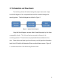
Daniel Kunz
[email protected]
Cell: 435-406-1567
Michael Engh
[email protected]
Cell: 435-757-4134
Jared Jeppsen
[email protected]
Cell: 435-740-0356
Curtis Ostrander
[email protected]
Cell: 435-770-1648
Thursday May 5th, 2011
Donald Cripps
Electrical and Computer Engineering Department
Utah State University
Dr. Cripps,
Included is our final documentation for our senior project. This project has given us a
significant understanding into the work that is involved in developing a product for the
commercial market. The document includes our initial idea, the decisions we made, the
development of our product, as well as suggestions or changes we would like to implement in
our design if we were not under a time constraint. Overall we are pleased with the end result,
and we are sure you will be as well. We appreciate your helpful insight and encouragement as
we researched, developed, and implemented this project.
Sincerely,
Daniel Kunz
Jared Jeppsen
Michael Engh
Curtis Ostrander
Senior Project: Final Report
Small Business Security
ECE 4840/4850
May 5th, 2011
Daniel Kunz, Jared Jeppsen Michael Engh, Curtis Ostrander
Instructor Approval __________________________________
______________
Dr. Donald Cripps
Date
Electrical and Computer Engineering Department
Utah State University
ii
Abstract
The purpose of this project is to design an economical and efficient
method of supplying security to small business operators and owners. The
design of this system is to be modular for ease of expansion and upgradeability.
The economic advantage of such a system would be the lessening or removal
of a monthly fee paid to a security contractor. All costs would be incurred up
front or at the time of expansion or upgrade.
iii
Table of Contents
Abstract ......................................................................................................................... iii
Table of Contents ....................................................................................................... iv
List of Tables ............................................................................................................... vi
Table of Figures ......................................................................................................... vii
Acknowledgements.................................................................................................. viii
1.0 Introduction ............................................................................................................ 1
1.1 Problem Statement and Design Objectives ............................................... 1
1.2 Summary of Design Process You Executed.............................................. 2
1.3 Summary of Final Results .............................................................................. 2
1.4 Organization and Summary of Report......................................................... 2
2.0 Conceptual Review and Preliminary Design ................................................. 3
2.1 Problem Analysis .............................................................................................. 3
2.1.1 Review of Problem....................................................................................... 3
2.1.2 Summary of Specifications ......................................................................... 4
2.1.3 Technical Approach ..................................................................................... 4
2.1.3.1 Basic Design Concept ......................................................................... 4
2.1.3.2 Access and Perimeter Solutions ........................................................ 5
2.1.3.3 Control Solutions .................................................................................. 7
2.2 Decision Analysis ............................................................................................. 7
2.2.1 Access Module Decision Process ............................................................. 8
2.2.2 Perimeter Module Decision Process......................................................... 9
3.0 Basic Solution Description............................................................................... 10
3.1 Schematics and flow sheets ........................................................................ 12
4.0 Design of System Components ...................................................................... 16
4.1 Description of Components/Specs ............................................................ 16
4.2 Discussion of Design Detail ......................................................................... 17
4.3 Fabrication, Construction, or Production Instructions/Specs. .......... 26
4.4 Summary of Final Design Results .............................................................. 27
5.0 Project Implementation and Operation ......................................................... 28
5.1 Details of Implementation ............................................................................. 28
5.2 Operational Test Results .............................................................................. 29
5.3 What Improvements are Suggested by the Design Results................ 30
6.0 Final Scope of Work Statement....................................................................... 31
6.1 Summary of Completed Work ..................................................................... 31
6.2 Summary of Additional Work....................................................................... 31
6.3 Lessons learned .............................................................................................. 31
6.4 Related project management issues ......................................................... 32
7.0 Other Issues ......................................................................................................... 33
7.1 Material Selection ........................................................................................... 33
7.3 Safety ................................................................................................................. 33
7.4 Societal Impact ................................................................................................ 33
7.5 Maintenance ..................................................................................................... 34
7.6 Contracts and Other Legal/Ethical Issues ............................................... 34
iv
7.7 Customer Support and Training ................................................................. 34
7.8 Product Documentation ................................................................................ 35
8.0 Cost Estimations ................................................................................................. 36
8.1 Estimate of System Costs ............................................................................ 36
8.2 Estimate of Design Cost ............................................................................... 37
9.0 Project Management Summary ....................................................................... 38
9.1 Time: Activities, Duration, and Order ........................................................ 38
10.0 Conclusion ......................................................................................................... 40
Appendix A – Canakit UK1104 Specifications ................................................... 41
Appendix B – Phidget RFID Specifications ........................................................ 42
Appendix C – SECO-LARM SK-990AQ Specifications .................................... 43
v
List of Tables
Table 1 - Part Suppliers .............................................................................................. 33
Table 2 - Project Cost ................................................................................................. 36
vi
Table of Figures
Figure 1 - System Block Diagram ............................................................................. 12
Figure 2 - Monitoring Block Diagram ........................................................................ 13
Figure 3 - Door Access Block Diagram .................................................................... 14
Figure 4 - GUI Interface Flow Chart .......................................................................... 15
Figure 5 - Schematic Diagram for Door Access ..................................................... 18
Figure 6 - Detailed System Block Diagram.............................................................. 19
Figure 7 - Main GUI Screen ....................................................................................... 20
Figure 8 - GUI Security Notification Settings Screen ............................................. 22
Figure 9 - GUI Security Badge Management Screen ............................................ 23
Figure 10 - GUI Surveillance Screen ........................................................................ 24
Figure 11 - GUI Log View Screen ............................................................................. 25
Figure 12 - Gantt Chart ............................................................................................... 38
vii
Acknowledgements
We would like to acknowledge our spouses: Annalese Kunz, Sarah
Jeppsen, Tasha Engh, and Debra Ostrander. Their understanding and support
during the many hours we were absent from our families allowed us to complete
our design on time.
viii
1.0 Introduction
With the continuing uncertainties of the current economy, the need for a
security system designed around a small business is essential. Our aim is to
develop a system that is completely internal and controlled entirely by the
business owner, rather than an outside monitoring company. This would help
reduce costs dramatically by eliminating the need of a monthly security
subscription fee.
1.1 Problem Statement and Design Objectives
Many small retail businesses would benefit greatly from a security
system that is cost effective, user friendly, and expandable. The design of this
system is centered on a three level structure: low, medium, and high. Low level
access will be granted by a radio frequency (RF) badge scanner. Medium level
access will also be granted by an RF scanner and will have a camera that takes
a picture of the person attempting to access the area. High level access will be
granted by an RF scanner, a numerical code, and also have a camera that will
take a picture of the person accessing the area.
Because of the modular approach, components, such as the camera,
numerical keypad, electromagnetic locks, and door alarm sensors, can easily
be added or taken away from any door according to the need and desire of the
business owner.
To make the system easy to use, a graphical user interface (GUI) will be
created that gives all the control to the business owner. The GUI will allow the
1
user to program employee badges with their applicable numeric codes and also
assign security clearance levels.
1.2 Summary of Design Process You Executed
We began our design by weighing the pros and cons of different security
system components. After researching the different options, we chose to
execute the design using components that were compatible with the universal
serial bus (USB). Our research also showed that writing software that would
access several devices simultaneously would be the best option.
1.3 Summary of Final Results
Final results show that coding for the individual components was indeed
simple. The only component that proved to be overly difficult was the camera.
This is because only one camera could be accessed at a time. A GUI has been
created that grants control of the system to the business owner.
1.4 Organization and Summary of Report
The purpose of this document is to review the overall design, design
solutions, performance optimization, project implementation, the final result, and
any other issues that arose while doing this project.
2
2.0 Conceptual Review and Preliminary Design
Design considerations will be covered in two major sections, an analysis
of the problem and a design analysis.
2.1 Problem Analysis
The analysis of the problem will be covered in the following sections: a
review of the problem; a summary of the specifications; and a technical
approach.
2.1.1 Review of Problem
The design criteria will be to create a security system which will be
economic, easy to operate, and easy to upgrade or expand.
The economic considerations are the cost of initial installation and any
upgrades or expansions to the system. Unique to this design will be the
removal of any costs associated with monthly fees paid to a security contracting
service.
To create a user-friendly design, the system will have a Graphical User
Interface (GUI) to operate the system once installed. The GUI will allow the
operator to enter or modify a security badge, allow access to any cameras, and
alert the monitoring security personnel via text messaging and e-mail in the
event of a security issue. Alerting any emergency personnel, such as the police
or fire department, shall be the responsibility of the customer or his delegates.
Upgrading or expansion of the system can occur easily due to a modular
design. Modules will consist of a range of either entry modules or perimeter
3
modules. Entry modules can be configured according to the security control
desired such as basic, intermediate, or advanced security. Perimeter modules
can consist of window modules, interior or exterior surveillance cameras, and
even parking lot access gates.
2.1.2 Summary of Specifications
A summary of the design specifications are as follows:
•
Low cost
•
Modular Design
•
User-Friendly
•
Easy to Upgrade or Expand
2.1.3 Technical Approach
The technical approach to our design will be discussed in the following
sections; the basic design concept, access and perimeter solutions, and control
solutions.
2.1.3.1 Basic Design Concept
The concept of this design is one which uses a central computer utilizing
an event driven security program operating with a GUI. An event can be raised
by a given access module such as an access request or an unauthorized
access (I.E. Opening of a door without using a security point). Additionally the
perimeter security modules can trigger an event by detection of a fire, loss of
power, or unauthorized access of a window or roof hatch.
4
In the event of a security issue, the security program will set a visual and
audible alarm and send an emergency notification message via text messaging
and/or e-mail to each person in the notification list.
2.1.3.2 Access and Perimeter Solutions
Possible access solutions available for use are numerous. The following
list shows access methodologies available:
•
Keypad and/or Cipher Locks
•
Magnetic Strip Readers
•
Proximity Badge Readers
•
Fingerprint Readers
•
Retinal Scanners
Each of these solutions contains their own unique advantages and
disadvantages. An examination of each possible access solution is made with
our design criteria in mind.
Keypad and cipher lock solutions have the advantage of being low cost
to implement, but have many disadvantages. The disadvantages of this
solution are the difficulty in monitoring access, detecting the number of attempts
to access, and the ease in breaking the access code. Additionally, it relies on
the ability of the user to remember their access code.
Magnetic strip readers provide several advantages, those being the low
cost of readers, the magnetic strip can be implemented on an employee badge,
and the ability to monitor and grant access from a controlling device (computer).
The disadvantages are not numerous, but are important. These disadvantages
5
are: wear on the magnetic strip with multiple reads; possible demagnetization of
the magnetic strip from outside influences; and a technology level that is being
phased out in most businesses.
Proximity badge readers are a bit more expensive, but not excessively
so. They offer the advantages of being incorporated into an employee badge or
key fob, are not susceptible to wear, and are widely used in business today.
The proximity badge is not without disadvantages. The main disadvantage is
the ability for the proximity badge code to be read by an “eavesdropping” RF
reader. Another disadvantage is the need to carry an additional badge or fob if
it is not incorporated into the employee badge.
Fingerprint readers have the advantage of being very secure as an
individual’s fingerprint is unique. The disadvantages are: high cost, difficult to
incorporate from a programming standpoint, and the inability to read an
individual’s fingerprint under dry skin conditions.
Retinal scanners are much like fingerprint readers in the aspect of being
very secure due to the unique signature of an individual’s retina. However, the
disadvantages are weighty. They are: very high cost, technology still in the
experimental stages, and difficulty in programming retinal image recognition.
Perimeter solutions are methods in determining the state of a door,
methods in viewing the interior or exterior of the building, and detection
methods for a fire or loss of power. The simplest method for determining the
state of a door is by the use of a limit switch. Methods to view the interior or
exterior of a building will be determined by the functionality of the GUI interface.
6
There are two possible solutions available, USB or IP (Internet Protocol)
cameras. Detection methods for a fire or loss of power can be done using
commercial fire detectors and power monitoring devices.
2.1.3.3 Control Solutions
Control Solutions are the methods to be used to communicate with the
individual access and perimeter modules. There are two methods to consider,
that of a USB driven system or an IP Ethernet based system. Each method will
use a Graphical User Interface based program to react to events raised by the
individual access or perimeter module.
The USB system would use the common USB 2.0 communication port of
the controlling computer to communicate with one or more modules. Each
module will use a USB relay board to communicate with the controlling
program. USB hubs will be used to allow multiple modules, and USB extenders
or repeaters will be used to increase the distance between the controlling
computer and the individual module.
The Ethernet system would use IP addressing to communicate to each
module. Each module will be a microprocessor based solution that will
communicate to the controlling computer via Ethernet IP protocols. In effect,
this solution will be a distributed network system connecting the controlling
computer to the individual access or perimeter modules.
2.2 Decision Analysis
7
Based upon the direction the project team wanted to go and with the
limited budget the team had, it was decided to use a USB based system.
These parts were readily available for a reasonable price, and most of the USB
devices came with drivers for a windows based solution.
Additionally, the criteria requirements for our design helped us to
determine what solutions to arrive at for the access modules and what our
deliverables were to be. The decision process for the access modules is
discussed in section 2.2.1 of this document. The decision process for the
perimeter modules is discussed in section 2.2.2 of this document.
2.2.1 Access Module Decision Process
The decision for the access module requirements is based upon the
criteria of cost effectiveness and ease of integration into a complete system.
With the decision made to pursue a USB format control system, the following
modules were selected.
The main component of the access module was the device being used to
read the access badge. Due to cost constraints the retinal scanner and the
fingerprint reader were discarded immediately. The keypad and cipher lock
options did not lend themselves to the overall design of our system in the fact
there was no easy method of monitoring by the controlling computer as to when
these devices were accessed. This left the magnetic strip and proximity badge
readers for consideration.
8
After weighing the advantages and disadvantages of each, the decision
was made to use the proximity badge reader for our design. Proximity badge
readers have a variety of interface selections with a USB format being one of
them. This type of proximity badge was selected for our design.
2.2.2 Perimeter Module Decision Process
For perimeter modules, a USB format webcam was selected for
perimeter cameras and a USB relay board was selected for the communication
pathway between the access module and control computer.
9
3.0 Basic Solution Description
As outlined above, the purpose of this project was to create a security
system that would be independent of a security company. This would allow the
owner of the business to have more control over the monthly financial costs of
the security system. Since this was going to be a security system controlled by
the business owner, we decided to use the PC (Personal Computer) as the
control center for the security system. Since the PC is a common tool available
to nearly every business owner, it would allow us to keep the costs down.
Since we decided to use the PC as the center of the security system, we
chose to use the USB (Universal Serial Port) to interface with the peripherals for
the security system. Although this technology is not new by computer
standards, it has proven itself to be a viable communication medium due to its
widespread usage which has resulted in the USB being an industry standard in
PCs. However, one of the drawbacks that we had to investigate before we
could proceed was a distance limitation with the interface. USB cables have an
effective range of about 15 feet. This raised significant problems as the
components the computer would need to communicate with would be three to
four times this distance. We spent time researching the problem, and we were
able to overcome this issue by using a USB Ethernet extender. This extender
allows the USB signal to be broadcasted over the Ethernet cables within the
building. This extends the distance to approximately 200 feet.
Once we had been able to resolve the distance limitation, we started
looking for other components that a basic security system would need. We
10
decided to utilize electromagnetic locks that would be actuated by a USB relay
board. The relay board that we chose also had 6 channel inputs that would
allow us to monitor the status of each of the doors. We also chose the RFID
(Radio Frequency Identification) based on their USB compatibility. Once we
had these components, we started looking at USB devices that we could use to
increase the security on a door. We decided to implement a keypad and web
cameras.
Using these components we designed a GUI (Graphical User Interface)
to connect all of these components together. Using the GUI, an employer will
be able to view security logs, set up security notifications, program employees
and badges, as well as have control over each of the magnetic locks manually.
The owner will also be able to access the web cameras to monitor areas of his
business.
The design is set up to demonstrate three levels of security. The lowest
level of security is just an RFID badge reader. The middle level of security
incorporates a badge reader, as well as a web camera that takes a picture of
whoever scanned the badge. That image is then stored on the businesses
computer. The highest level of security will have an RFID badge reader, and
will also require the employee to enter a code into the keypad.
In the event a door is opened without authorization, an audible/visual
alarm will sound, and a notification will be sent out via text message and e-mail
to the contacts that the business owner has set up in the GUI.
11
3.1 Schematics and flow sheets
The first thing that we did when starting this project was create a high
level block diagram of the components that would be needed to design the
security system. The block diagram is outlined in Figure 1.
Figure 1 - System Block Diagram
Using this block diagram, we were able to break the project up into three
manageable chunks. The first one that we are going to discuss is the
monitoring devices. These devices are peripherals that are attached to the
door. These devices will take input from the user, and will pass the information
back to the GUI which will determine if the user should have access. Figure 2
is a further breakdown of the Monitoring Devices block.
12
Figure 2 - Monitoring Block Diagram
This block diagram breaks down how each component is connected to the
computer. Each of these devices would be connected to a door that needed
the additional security. Although the camera, keypad, and badge reader are all
mentioned in this block diagram, the user can specify which combination of
these devices the door should have. As outlined in the block diagram, each of
the connections is through a USB 2.0 connector. Each of the peripherals is
connected together at a USB HUB location. Then a USB extender would be
used between the USB hub and the computer. Figure 3 is a further breakdown
of the devices that will be used to control the access to the door.
13
Figure 3 - Door Access Block Diagram
The connection between the computer and the USB relay will be through the
USB extender, and USB cables. The USB relay is what will control the actual
door access mechanism. When the GUI determines that a valid scan has taken
place, the relay is closed, and the electromagnetic lock receives the power.
These electromagnetic locks are fail-secure, meaning if they do not have
power, they are locked. Once the locks receive power, they release the striker
plate and allow the door to be pushed open. Also, if the GUI determines that
there is unauthorized access, the relay controlling the alarm will be actuated,
and this will sound an audible/visual alarm. Figure 4 is a flow chart for the GUI
interface.
14
Figure 4 - GUI Interface Flow Chart
The above flow chart explains the functionality of the GUI interface. This flow
chart explains the functionality of the peripheral devices and how they interact
with the door access mechanisms. This flow chart is an explanation of how the
GUI will interact with a high security door that has the badge reader, web
camera, and keypad.
15
4.0 Design of System Components
In this section we will discuss in detail about each of the components
used in the security system, as well as the features of the GUI that were
developed for the control of the system. We will also discuss the final build
information, in addition to the summary of the final design results.
4.1 Description of Components/Specs
In this section, we will give in depth information concerning each of the
components that we chose to use for our security system. Although this will not
be an all-inclusive list of features, we will mention the ones that are specific to
the security system.
Phidgets RDIF Badge Reader – One of the first components that we
chose was the RFID badge reader. This badge reader has a USB interface, a
5v relay that can be used to control two LEDs, and libraries that will allow us to
write code to interact with the badge readers.
Canakit 4 Relay/6 Channel USB Board – The next component that we
had to choose was a relay board that would be used to actuate the
electromagnetic locks. This board has four relays. Each of these relays are
rated at 5A at 110v which is more than enough for the electromagnetic locks.
The board also has a 6 channel input/output interface. Each of the channels
can be configured to monitor a 5v source that is also provided by the board.
This USB board communicates with the computer through an emulated serial
communication port.
16
iHome Web Cameras – We chose these cameras based on cost, as well
as the Megapixels. Each camera is capable of a 5 mega pixel picture and
communicates with the computer through the USB 2.0 interface.
Targus 9 Digit Keypad – This is a keypad which has the necessary 9
digit interface, and it communicates through a USB interface.
Dynex 7 port USB hub – This is a 7 port powered USB hub. This hub is
intended to increase the connectivity of a single USB port on the controlling
computer.
Electromagnetic Door Strikes – These door strikes are used to replace
the door strikes in the frame. They are a fail-secure style strike. This means if
there is a power failure, the doors will stay secure. The Magnetic locks require
10-14VDC, require 450mA of current, and have an internal resistance of 26
ohms.
Limit switches – This was a switch used to monitor door access. These
switches were 5A 120v rated.
Power Supply – The power supply for the locks takes a 100-240V
50/60Hz .6A max input, and outputs 12v at a maximum of 2 amps.
4.2 Discussion of Design Detail
In this section we will review the overall design and schematics for the
wiring of the system, as well as a design review of the GUI. Figure 5 below is a
schematic of the circuit that describes how the USB relay, power supplies, and
electromagnetic locks are connected.
17
Figure 5 - Schematic Diagram for Door Access
Each of the relays are kept in the normally open position. This means that no
current is reaching either the alarms or electromagnetic locks. Once the relay is
closed, the circuit is completed, and the alarms and locks will be actuated. The
figure below (Figure 6) is a block diagram of how each of the components
would be connected to the main computer. The security peripherals (badge
reader, keypad, and web camera) all send information about the user back to
the GUI, which in turn decides if the user should be allowed to enter. If the GUI
determines that the user should have access, a command is sent to the USB
relay that will open the electromagnetic lock.
18
Figure 6 - Detailed System Block Diagram
In the next section, we will be reviewing the different features of the GUI
that will be used to control the security periphrials. Figure 7 is the main GUI
interface.
19
Figure 7 - Main GUI Screen
The first thing the user will notice is the text box at the top of the screen.
In this box the notifications will be diplayed for the user to see. The notifications
will include invalid badge scans, valid badge scans, and alarm notifications. In
addition to displaying this information, the GUI will also save all of this
information in a text file. Directly beneath the text box on the left hand side,
there are three buttons. Their functions are described below:
Security notifications: This will open up another form that will allow you to set
up the security notifications for when the alarm goes off. This will be
discusssed in further detail below.
20
Reset Alarm – When the user clicks on this button, the audible/visual
alarm will be turned off, the action will be recorded in the list box, and the GUI
will start monitoring the doors for security again.
Disable Alarm – When the user clicks on this button, the GUI will stop
monitoring the doors.
Alarm Status Box – The box to the right of these buttons (shown in green
above) displays the status of the alarm. When the alarm is working normally, it
will display the green box with the text “Secure” in the middle. When the alarm
is tripped, the box will alternate between green and red getting the attention of
the user. The text will also change in the box from “Secure” to “Alarm!” When
the user resets the alarm, this box will go back to green with the “Secure” text.
If the user clicks on the “Disable” button, the text will change to “Disabled” and
the box will turn gray.
The next part of the GUI are the “Badges”, “Surveillance”, and “View
Logs” buttons. Each of these buttons will open up a new window with different
functionality that will be outlined further below. The final buttons are manual
overrides. If the user clicks on the “Open” Button, the corresponding door relay
will remain open until the user clicks on the “Closed” Button. When the user
clicks on the “Closed” button, the door will be monitored for access through the
GUI as normal. The next section in the GUI (Figure 8 page 22) is where the
user will go to set up the security notifications.
21
Figure 8 - GUI Security Notification Settings Screen
On the left hand side there is a box that will contain all of the text
messages and e-mail addresses that will be notified if there is a security
problem. If the user needs to remove a contact from this list, they will need to
simply click on the contact, and then click on the “Remove Entry” button. If the
user would like to add a contact, they will just need to enter the e-mail
address/text message address to the box in the “Add Contact” section and click
on the “Add Entry” button. This will add the contact to the list box at the top of
the window. On the right hand side the user will need to set up their e-mail
address. The program will send out the notifications through the users e-mail
address. You will also be able to modify the message that is sent out to the
contacts in the text box in the bottom right side of the window. In the bottom of
the “Notification Message” box, there are three buttons. One will allow you to
send a test message to the contact list, the save changes button will save any
22
changes that you made to the e-mail settings or notifcation message. The final
button “Discard Changes” will allow you to discard any changes that you made
to your settings. If you have made changes and click on this button, the
changes will be replaced with the last saved settings. The next figure (Figure 9)
is the window where the user can control and administer the badges that are
programmed in the system.
Figure 9 - GUI Security Badge Management Screen
There are three ways to look up an employee or card information. The
first will be to simply scan the badge. When the badge is scanned, the RFID
number is displayed in the box. The next way is to manually enter the RFID
number. The final way is to select the Employee option. When the user selects
this option, it will create a drop down list of the names of every employee that is
on record. Once a badge is scanned or typed; or an employee is selected from
the drop down, the user can then click on the “View Badge Data” button. This
will fill the boxes on the right hand side of the screen with the employee data. If
23
the badge is not currently associated to an employee, the fields will display N/A.
If the user would like to make changes to the badge, or to the permissions, they
can click on the “Edit Badge Details” Once you have clicked on this button, you
will be able to alter all aspects of the details, including what doors the employee
should have permission to access. Once any changes are made, the user will
need to click on the “Save Badge Data” The information will then be saved and
a message box will pop up prompting the user that the information has been
saved. Similarly, if the user wants to remove an employee, once the boxes are
filled out on the right by clicking on the “View Badge Details” button, they will be
able to click on the “Remove Badge” button. This will prompt the user to make
sure they want to remove the employee. Once they confirm they want the
employee removed, the contents will be removed, and the user will receive a
message letting them know the information was successfully removed. The
next figure (Figure 10) displays the web camera footage in real time.
Figure 10 - GUI Surveillance Screen
24
This will allow the user to monitor the business in real time. If you click on the
start button, it will start the stream. This will not happen automatically to reduce
the load on the computer. When the user is done looking at the feed, they can
either close the window, or select the “Stop” button. The final section of the
GUI (Figure 11) is how the user will review the logs.
Figure 11 - GUI Log View Screen
The final section of the GUI is the log viewer. This will allow the user to
look over the logs since the system was installed. It displays when a badge
was scanned, whether it was valid or not, if an alarm was triggered and which
25
door triggered it, and also if the alarm was reset or disabled. If the user would
like to see the associated web cam picture with a particular door that has a web
camera installed, they would simply need to double click on the entry in the text
box and the image would pull up in a window.
4.3 Fabrication, Construction, or Production
Instructions/Specs.
The demo doors that we have were fabricated by Cantwell Bros. Lumber
Company. However, due to the fact that they have not been mounted in a wall,
we had to come up with a way of standing them up so that when you open a
door, they do not fall over. Using some scrap lumber we were able to fabricate
stands with support arms that hold the door frames in place and create the
stability needed to open the doors. The door jambs all had to be carved out by
hand to fit the door strikes and door knobs. This was done using a hammer and
chisel. The limit switches that are used for monitoring the doors were placed in
the upper corner in such a way that when the door is closed, the switch is
actuated.
The 9V power supply was modified to accommodate the amount of
grounds needed for the relays and door strikes. All grounds are common
through the power supply. The door strikes receive their power via their
respective relay. The alarm also receives power from the relay. The limit
switches receive their power from the +5V channel pins located on the relay
board. The other channel pins monitor each of the switches individually waiting
for a signal that the door has been opened. For the demonstration, the RFID
26
badge readers, camera, and keypad will all be mounted on the top of their
respective doors.
4.4 Summary of Final Design Results
In summary we learned quite a few different lessons in the design
process. If we started again from scratch, there are several things we would
have done differently. However, since we were limited on time, we decided to
make the best that we could out of the project we set out to create. I believe we
were able to accomplish this with a few minor setbacks. Those setbacks will be
outlined in section 5 below.
27
5.0 Project Implementation and Operation
The implementation of the project was done in many different steps to
limit the number of errors and be more efficient. The careful implementation of
the different components were tested and retested to ensure success. The
results and suggested changes are discussed later in this section.
5.1 Details of Implementation
The project was separated into different sections of code depending on
the hardware used. Similar hardware was coded in the same section to
eliminate many sections and simplify the project. The four sections that we
used were GUI, control coding, proxy reader coding, and camera coding. The
GUI code included the interface for the user to work with. The control coding
included the USB relay that opens the locks and checks the door status. The
proxy reader coding included the RFID scanners and the keypad to allow
access. The camera coding included the webcams used to snap pictures of
those that entered certain levels of security.
The different sections of code were written, tested, and retested
separately to limit the number of errors when implemented with the other
sections. The sections that were combined together first were the GUI and the
control coding. These were worked on first and implementing them was of ease
because of the amount of testing and troubleshooting that was done. The proxy
reader coding was then implemented, it was a little more difficult
troubleshooting and debugging. The three sections combined were tested and
debugged to eliminate all the errors and glitches in the system. The camera
28
coding was the most difficult to implement because of the number of errors
encountered. USB cameras were not as easy to incorporate because it was
very hard to switch between cameras in the code when needed.
5.2 Operational Test Results
The testing of the system was done throughout the coding and
combining of code to simplify the project. After combining the code and setting
up the different doors with the security measures in place the program was
executed. We found the system ran as expected minus a few glitches that were
easily fixed. The most difficult part of the system was the webcams.
The RFID scanners worked as expected, upon a badge scan it would
check a text file for that badge to ensure it had clearance and it would log into a
text file the time, date, and badge number. If the badge had clearance it
opened the door and started a timer to limit the amount of time the door was
opened.
The second level of security had the webcam integrated on it and every
time a badge was scanned a picture was taken and saved in a file with the time
and date.
On the third level of security when the badge was scanned it checked a
file to ensure clearance if the badge was cleared it waited for a key code to be
entered. Upon a correct key code with the proper badge the door would open
starting a timer. The USB relay used would check the status of the switches on
the doors to ensure they are closed when needed. When a door was open for
too long or opened without permission the alarm would sound and text
29
messages were sent to individuals designated by the owner. The system had
met criteria specified before.
5.3 What Improvements are Suggested by the Design
Results
The changes that would be suggested and considered in doing this
project again would be the design and types of webcam. The design would be
different by using microcontrollers at each door instead of one computer
controlling many doors. The design change would simplify the project and
make it more efficient in adding new modules to the system. It would make it
easier to add things to existing doors as well. The webcams would be changed
to IP (Internet Protocol) cameras to simplify the coding a lot and make it work
more effectively. The IP cameras would make it easier to switch between
cameras, be more secure, and have better resolution.
30
6.0 Final Scope of Work Statement
The project is near completion and meets most of the requirements
specified. The original timeline had to be modified to include the testing times
but it did not set us back. The reason it is not complete is the complexity of the
webcams discussed later in this section.
6.1 Summary of Completed Work
The criteria for the project have been completed. There are three levels
of security the first having just a RFID scanner, the second RFID scanner and
camera, and the third level RFID scanner, camera, and keypad. The doors are
being monitored all the time to make sure no unauthorized entries occur. There
are timers on the doors so they are not opened for more than 10 seconds. The
keypad on level three is only activated after a valid badge scan and it allows for
five seconds for a code to be entered. The alarm sounds when the door is
opened without authorization or the door is opened for more than 10 seconds.
6.2 Summary of Additional Work
The task that has not yet been completed is the camera code. The
cameras have been the hardest to code. We still need to figure out how to
change between cameras in the code, snap a picture and load the picture to a
file.
6.3 Lessons learned
The project has been a great opportunity to learn and grow. There have
been many valuable lessons learned throughout the whole process. Selecting
31
the hardware for this project was a great lesson. It is always great to do
extensive research on a piece of hardware and its limitations before moving
forward. The hardware that we found and researched was all USB compatible
so we use the USB to support our program. This was found to be harder and
more complicated than having microcontrollers at each door and talking through
IP.
The initial USB hub purchased was thought to have been a powered hub
and capable of operating all the components needed. After receiving the hub,
that was not powered, and connecting it to the components and central
computer it would disconnect different components at different times. The
second USB hub we purchased was a powered hub and it ran all the
components needed very well.
6.4 Related project management issues
The project management was very good. We accomplished our goals in
a timely manner and as expected. One item that was addressed after the first
timeline that was made was the testing time. The time allotted for testing was
not on the timeline so it needed to be added in. It worked out great because it
did not slow down the progress of the project with being able to test the code
while still writing new code. This was accomplished because of a multiple
person team. The webcam code has taken longer than expected because of
the complexity of the code, but hopefully will be completed before the final
project. The rest of the project went smoothly and followed the timeline as
expected.
32
7.0 Other Issues
This section of the document covers the materials we chose to use, who
we obtained them from, and the overall impact of our project.
7.1 Material Selection
The following table provides a materials list and their associated supplier.
Table 1 - Part Suppliers
Material
RF ID Scanners and Badges (3)
USB Relay
Keypad
Limit Switches (3)
Camera
18 Gauge Wire
Doors (3)
Door Knobs (3)
USB Hub
USB Extension Cable
Alarm
Door Strikes (3)
9V, 2A Power Supply
Wire Nuts (26)
Supplier
Robot Shop Inc.
Spark Fun Electronics
Targus through Amazon.com
USU ECE Store
ambientweather.com
Wal-Mart
Cantwell Bros Lumber Company
Wal-Mart
Best Buy
Amazon.com
Amazon.com
Discount Home Automation
Deseret Industries
USU ECE Store
7.3 Safety
The only safety issue that we came across was during the wiring of all
the components. Upon installation, a licensed electrician should be consulted.
7.4 Societal Impact
Allowing a business owner to be in complete control of their security will
bring peace of mind to that individual. Using a contracted company to watch
your security system can be unnerving because you never know how many
people have access to your information and the threat of theft is always
constant.
33
7.5 Maintenance
Maintenance of this system will be relatively low. The USB relay has no
mechanical devices controlling the switches, thus making it extremely low
maintenance. The electromagnetic locks also will require very little
maintenance. The only component that would require regular maintenance is
the limit switch. Extensive use of the switches will result in failure to achieve a
proper connection. However, if we were to go commercial with this product, we
would upgrade to a magnetic sensor bar instead because of the little
maintenance needed for those.
7.6 Contracts and Other Legal/Ethical Issues
If we were to go commercial with this product, we would need to obtain
rights to licensing from Phidgets, the manufacturer of the RF ID scanners, for
the software libraries that we used for the GUI.
7.7 Customer Support and Training
Upon installation of the security system, we would send a well trained
associate to install the software on the business’s computer and train the
business owner how to use the program. We would also offer additional
assistance and training during regular business hours by telephone or by an
appointment. Customer satisfaction is guaranteed.
34
7.8 Product Documentation
The security system would come with an executable CD that would
download all the programming on the customer’s computer. A user manual
would also be developed and included with the purchase of the security system.
35
8.0 Cost Estimations
The following section will cover the cost estimates of the entire project.
This would include all of the parts, in addition to any materials needed to create
a demonstration model.
8.1 Estimate of System Costs
The following table shows the complete materials list with the associated
cost.
Table 2 - Project Cost
Material
RF ID Scanners and Badges (3)
USB Relay
Keypad
Limit Switches (3)
Camera
18 Gauge Wire
Doors (3)
Door Knobs (3)
USB Hub
USB Extension Cable
Alarm
Door Strikes (3)
9V, 2A Power Supply
Wire Nuts (26)
Construction Materials
Total
Cost
$210
$67.53
$7.63
$7.00
$55.14
$10.00
$138.98
$30.00
$13.00
$2.65
$19.75
$77.42
$1.00
$2.80
$5.00
$647.90
The estimated budget for this project was estimated to be about $600.
We met the budget with the actual cost of all the parts, but failed to take into
account the shipping of the components. Because of shipping costs, we ended
up going a little over our estimated budget.
36
8.2 Estimate of Design Cost
The design of the project was split into two parts: software development
and hardware construction. The majority of the time spent on the project was in
the software development. Parts of the coding were more difficult than
originally anticipated. Hardware construction was fairly straightforward. The
development of the entire project took approximately 800 total man-hours to
complete.
37
9.0 Project Management Summary
The project followed the timeline closely after we had made the changes
to accommodate for the testing time. The main problem we had during this
project was the webcam coding. Webcams took a lot longer to code and figure
out than expected so we combined all the code we had other than the webcams
and tested it. The program runs great and does all that is required from the
beginning.
9.1 Time: Activities, Duration, and Order
In this section we will display the Gantt chart and briefly discuss the
activities, duration and order. Although most of this information was covered in
Sections 6.1 and Section 6.2 we will discuss some of the points in more detail.
Figure 12 below shows the Gantt chart that was followed throughout the project
to keep us on track.
Figure 12 - Gantt Chart
38
Most of these tasks were handled as a group. However, each of these
tasks had an individual in charge of coordinating the work for that section. The
GUI and coding was handled by Daniel Kunz. The construction was handled by
Michael Engh. The ordering of parts and research of web cameras was
handled by Curtis Ostrander. The final construction and testing was handled by
Jared Jeppsen. Although the project is mostly complete at this point, we did fall
slightly behind due to the complexities of programming a web camera. We still
need to finalize the code for this device, as well as do a thorough testing of the
complete environment as a working user interface.
39
10.0 Conclusion
In conclusion, our project had the focus of creating a small business
security system that could be utilized by the owner, without incurring the
monthly subscription fees associated with security systems. We were able to
accomplish this by basing the design around an interface that would be used on
the business’s computer.
Although we were able to complete our project and produce a
deliverable, the lessons we learned throughout the design process will help us
refine our design into a more marketable product. Tools such as the Gantt
chart were crucial in helping manage our time and meet our deadlines. Even
though it took the entire semester to finish the project, the Gantt chart allowed
us to more evenly spread our time so the final product was higher quality and
not rushed towards the end of the semester.
40
Appendix A – Canakit UK1104 Specifications
http://www.canakit.com/Media/Manuals/UK1104.pdf
41
Appendix B – Phidget RFID Specifications
http://www.phidgets.com/products.php?category=14&product_id=1023
42
Appendix C – SECO-LARM SK-990AQ
Specifications
http://www.seco-larm.com/SK990b.htm
43