1
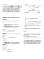
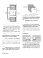
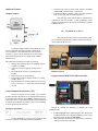
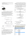
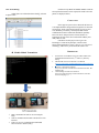
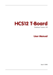
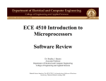
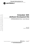
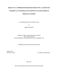
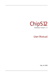
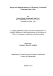
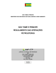
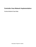
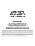
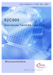
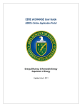
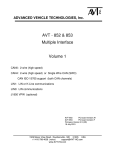
CAN Protocol Implementation Arun Pasupathi, Gaurav Agalave Electrical and Computer Engineering Department School of Engineering and Computer Science Oakland University, Rochester, MI e-mails: [email protected], [email protected] I. INTRODUCTION The report will cover the methodology and implementation of CAN Communication Protocol using the HCS12 Microprocessor. To give a short introduction about CAN, The controller area network (CAN) was initially created by the German automotive system supplier Robert Bosch in the mid-1980s for automotive applications [1] as a method for enabling robust serial communication. The goal was to make automobiles more reliable, safe, and fuelefficient while at the same time decreasing wiring harness weight and complexity. Since its inception, the CAN protocol has gained widespread use in industrial automation and automotive applications. We have managed to cover Topics such as ASM which is assembly Level Programming (for Delays), Timer Function (Using Output Compare) and Interrupts (OC5 interrupt for Output Compare & Reg. CANnRIER for Receiver Interrupt), which are to be discussed in detail in the below topics. II. METHODOLOGY Overview of CAN: To achieve design transparency and implementation flexibility CAN has been subdivided into three layers [1], • Object Layer: determines which messages are to be transmitted; deciding which messages received by the Transfer Layer are actually to be used; and, providing an interface to the Application Layer related hardware. There is considerable freedom in defining object handling. • Transfer Layer: The Transfer Layer is principally concerned with the transfer protocol, i.e. controlling the framing, performing arbitration, error checking, error signaling and fault confinement. • Physical Layer: The Physical Layer covers the actual transfer of the bits between the different nodes. Within a network the physical layer has to be the same for all nodes. The CAN communication protocol is a CSMA/CD protocol. The CSMA stands for Carrier Sense Multiple Access. CD stands for Collision Detection. CAN is a message based protocol. A message can be defined as a packet of data which carries information. A CAN message is made up of 10 bytes of data. Messages in CAN are sent in a format called frames. A frame is defined structure, carrying meaningful sequence of bit or bytes of data within the network. Framing of message is done by MAC sub layer of Data Link Layer .There are two type of frames standard or extended. These frames can be differentiated on the basis of identifier fields. A CAN frame with 11 bit identifier fields called Standard CAN and with 29 bit identifier field is called extended frame. Standard frame: Various fields in standard CAN are as follows SOF - Start of Frame bit. It indicates start of message and used to synchronize the nodes on a bus. IDENTIFIER - It serves dual purpose one, to determine which node has access to the bus and second to identify the type of message. RTR - Remote Transmission Request IDE – Identifier Extension R0 - Reversed bit DLC – Data Length Code. It is 4 bit data length code that contains the number of bytes being transmitted. DATA– Used to store up to 64 data bits of application data to be transmitted. CRC– Cyclic Redundancy Check ACK – Acknowledge (ACK) field. It compromises of the ACK slot and the ACK delimiter. When the data is received correctly the recessive bit in ACK slot is overwritten as dominant bit by the receiver. EOF– End of Frame (EOF). The 7-bit field marks the end of a CAN frame (message) and disables Bit - stuffing, indicating a stuffing error when dominant. IFS - Inter Frame Space that specifies minimum number of bits separating consecutive messages. Extended Frame: It is same as 11-bit identifier with some added fields SRRSubstitute Reverse Request. The SRR bit is always transmitted as a recessive bit to ensure that, in the case of arbitration between a Standard Data Frame and an Extended Data Frame, the Standard Data Frame will always have priority if both messages have the same base (11 bit) identifier. R1- It is another bit not used currently and kept for future use. CAN0IDAC = 0x10 // Identifier-Acceptance Control Register - Set four 16-bit Filters 00010000 || |||__ || ||___\_ Filter Hit Indicator || |____/ ||______ |_______>- Four 16-bit Acceptance Filter Set the Acceptance and Mask Registers CAN0IDAR0 ~ CAN0IDAR7 and CAN0IDMR0 ~ CAN0IDMR7. Mask registers are used to determine which bits of the acceptance registers would be used to filter the incoming messages. CAN0CTL0 = 0x00 // Exit Initialization Mode Request Exit Initialization mode and wait for normal mode. Initialization, Transmit and Receive Logic of CAN: Initialization: The process of Initialization is one of the most important phases in CAN Protocol, which is explained in detail as follows, CAN0CTL0 = 0x01 // MSCAN Control Register 0 Enter Initialization Mode Wait for Initialization Mode acknowledge INITRQ bit = 1 CAN0CTL1 = 0x80 // MSCAN Control Register 1 Enable MSCAN module and LoopBack Mode 10100000 | |_______ Loop Back Mode Enabled |_________ MSCAN Module Enabled CAN0BTR0 = 0x03 // MSCAN Bus Timing Register 0 00000011 ||||||||__ |||||||___\ ||||||____ | |||||_____ |_ CAN Clock Prescaler = 4 ||||______ | |||_______ | ||________/ |_________>- SJW = 1 tq clock cycle CAN0BTR1 = 0x3A // MSCAN Bus Timing Register 0 Set Number of samples per bit, TSEG1 and TSEG2 00111010 ||||||||__ |||||||___| ||||||____|- TSEG1 = 11 |||||_____| ||||______ |||_______\_ TSEG2 = 4 ||________/ |_________ One sample per bit Transmit: The main 2 goals achieved by MSCAN transmit-structure are Providing the capability to send out a stream of scheduled messages without releasing the bus between the two messages Prioritizing messages so that the message with the highest priority is sent out first As shown in the below figure, the MSCAN has a triple transmit buffer scheme that allows multiple messages to be set up in advance and achieve a real-time performance. Only one of the three transmit buffers is accessible to the user at a time. A transmit buffer is made accessible to the user by writing an appropriate value into the CANxTBSEL register. The procedure for transmitting a message includes the following steps: 1. Identifying an available transmit buffer by checking the CAN0TFLG register. If the buffer is full then flag is '0' else '1'. If CAN0TFLG is 0x00 then program will wait for empty buffer 2. Setting a pointer to the empty transmit buffer by writing the CAN0TFLG register to the CAN0TBSEL register, making the transmit buffer accessible to the user 3. Storing the identifier, the control bits, and the data contents into one of the transmit buffers 4. Flagging the buffer as ready by clearing the associated flag in CAN0TFLG After step 4, the MSCAN schedules the message for transmission and signals the successful transmission of the buffer by setting the associated flag in CAN0TFLG. If there is more than one buffer scheduled for transmission when the CAN bus becomes available for arbitration, the MSCAN uses the local priority setting to choose the buffer with the highest priority and sends it out. The buffer having the smallest priority field has the highest priority and is scheduled for transmission first. The internal scheduling process takes place whenever the MSCAN arbitrates for the bus. Receive: As shown in below figure, the received messages are stored in a five-stage input FIFO data structure. The message buffers are alternately mapped into a single memory area, which is referred to as the foreground receive buffer. The application software reads the foreground receive buffer to access the received message. The background receive buffer is solely used to hold incoming CAN messages and is not accessible to the user Whenever a valid message is received at the background receive buffer, it will be transferred to the foreground receive buffer and the RXF flag will be set to 1. The user’s receive handler program has to read the received message from the RxFG and then reset the RXF flag to acknowledge the interrupt and to release the foreground buffer. When the MSCAN module is transmitting, the MSCAN receives its own transmitted messages into the background receive buffer but does not shift it into the receiver FIFO or generate a receive interrupt. An overrun condition occurs when all receive message buffers in the FIFO are filled with correctly received messages with accepted identifiers and another message is correctly received from the bus with an accepted identifier. The latter message is discarded and an error interrupt with overrun indication is generated if enabled. The MSCAN is still able to transmit messages while the receiver FIFO is being filled, but all incoming messages are discarded. As soon as a receive buffer in the FIFO is available again, new valid messages will be accepted. CAN clock system:- The MSCAN clock generation circuitry is shown in above figure. This clock circuitry allows the MSCAN to handle CAN bus rates ranging from 10 kbps up to 1 Mbps. The CLKSRC bit in the CANxCTL1 register defines whether the internal CANCLK is connected to the output of a crystal oscillator or to the E-clock. The clock source has to be chosen such that the tight oscillator tolerance requirements (up to 0.4 percent) of the CAN protocol are met. Additionally, for a high CAN bus rate (1 Mbps), a 45 to 55 percent duty cycle of the clock is required. Additional Features: Output Compare: The baud rate selected is 9600, using registers SCI1BDH and SCI1BDL (0x00 and 0x9C respectively). Transmit and Receive Enable is done by writing 0x00 and 0x0C on SCI1CR1 and SCI1CR2 respectively. Here the logic of the entire module of transmission is controlled by the User interface, (i.e) the continuation of the program is also decided by the user by transmitting a continue command via SCI. III. EXPERIMENTAL SETUP The basic Project setup will be as shown below, with a PC to host the UI and Node A which is connected serially to the PC and Node B via CAN. The output compare function is actioned at receiver end, as creating the appropriate frequency based on the received data via CAN Communication. The generated frequency is given to the on board buzzer to create sound based on the input string. We are using output compare channel 5 for it. The initialization of channel 5 is done as following, Writing 0x20 on TIOS register for enabling Output Compare on Channel. Select OC5 action to toggle by writing TCTL1 = 0x0C. Pre-scalar factor is set to 2 by moving 0x01 to TSCR2. TOF and C5F are cleared manually Forced output compare function CFORC, by setting CFORC_FOC5 = 1. program will then wait until comparison success flag is set i.e TLFG1(5) = 1, which will cause an interrupt on OC5 Hardware Used: Dragon 12 board With HCS12 Microcontroller: Serial Communication Interface (SCI): The SCI is majorly used for getting a user interface through which the data which is to be transmitted through can is provided. This is done by using ‘Putty’ terminal from a PC. User will be asked to enter a data which then will be transferred to transmit node character by character. SCI receiver interrupt is used to get data given from user. Format of a SCI Frame: Dragon 12 contains the following to facilitate the CAN Communication, For SCI initialization we have to select baud rate and we have to enable receiving and transmitting operations. CAN0 (Highlighted the lighted Region) Port having the CANH and CANL slots, which are internally connect to the Rx and Tx of the Transceiver MCP2551. SCI Communication Interface to communicate to the PC to make the User Interface possible. 16 * 2 LCD which is used to display the Data which is to be transmitted and received. Buzzer at slot J25 which produces a sound when a particular frequency value is provide via PT5. MCP2551: Then from the Transmission node the Data that is communicated is sent to the Receiver Node via CAN Protocol. The Data then is sent across a series of IF Loops to get the corresponding value which hardcoded in the receiver side The value is sent to the Output Compare Function to generate a waveform, which then generates a sound using the On-Board Buzzer connected at Pin PT5. Then Finally the Transmission node checks for the Transmission continuation with the UI via SCI and waits till the next command or data is provided. The MCP2551 is a high-speed CAN, fault-tolerant device that serves as the interface between a CAN protocol controller and the physical bus. The MCP2551 device provides differential transmit and receive capability for the CAN protocol. It will operate at speeds of up to 1 Mb/s. It also provides a buffer between the CAN controller and the highvoltage spikes that can be generated on the CAN bus by outside sources (EMI, ESD, electrical transients, etc.). The typical Connection/Interface between MCP2551 and HCS12 is given below. IV. RESULTS The project has been carried out in two phases, Loop-Back Mode Before Transmission Start The value that is to be transmitted is stored in an array txbuff[] and has to be via CAN and stored in rxdata[]. Software Flow: The basic software or the control flow pertaining to the presented project is given below, As like every System in the Industry, the Command and Control Transfer authority is done via the User Interface which in the current project is provided by the PC (Putty Software) as shown in the Hardware Model. The Data and Control is Transferred to the Dragon 12 Board (Transmission Node) using the SCI Protocol (Serial Communication Interface), which is actually a short distance serial communication protocol. After Transmitting: rxdata[] has received the data from txbuff[], as shown in figure below. (Details of Loop-Back and Module-Module CAN has already been discussed in earlier topics) The results of bot the phases are displayed below, CONCLUSION In this project report we have discussed the basics of CAN Implementation along with the integration of CAN with SCI Protocol. Some of the unique benefits of CAN are Low cost, Reliability, Flexibility, Good Speed, Multi-master communication, Fault Confinement, Broadcast capability. Due to the above unique features CAN has number of application and uses in the current automobile industry and many others as well. Our Motive for this project was to get a fair knowledge of CAN and its principles, which we have achieved through the above steps. CAN is a very vast area of technology, and we have just scratched the surface of it. Module-Module Transmission REFERENCES 1. 2. 3. 4. Data is transmitted to Node A via SCI using the Putty. Node A communicates the Data to Node B via CAN Protocol There is a two way communication established between Node A and PC (Putty). HCS12/9S12 AN INTRODUCTION TO SOFTWARE AND HARDWARE INTERFACING (2nd Edition) by Han-Way Huang. MICROCHIP Transceiver MCP2551 User Manual (http://ww1.microchip.com/downloads/en/DeviceDoc/21667f.pd f) Freescale CAN Reference Manual (http://www.freescale.com/files/microcontrollers/doc/data.../BC ANPSV2.pdf) Understanding Controller Area Network (http://www.engineersgarage.com/article/what-is-controllerarea-network?page=1)