1
installation
and
user guide
hp StorageWorks
command view sdm
version 1.07
Edition September 2003
Part number T1086-96001
Notice
Trademark Information
© Copyright 2003 Hewlett-Packard Development
Company, L.P., all rights reserved.
Red Hat is a registered trademark of Red Hat Co.
C.A. UniCenter TNG is a registered trademark of
Computer Associates International, Inc.
Hewlett-Packard Company makes no warranty of
any kind with regard to this material, including,
but not limited to, the implied warranties of merchantability and fitness for a particular purpose.
Hewlett-Packard shall not be liable for errors contained herein or for incidental or consequential
damages in connection with the furnishing, performance, or use of this material.
This document contains proprietary information,
which is protected by copyright. No part of this
document may be photocopied, reproduced, or
translated into another language without the prior
written consent of Hewlett-Packard. The
information contained in this document is subject
to change without notice.
Format Conventions
WARNING
Identifies a hazard that can cause
personal injury
Caution
Identifies a hazard that can cause
hardware or software damage
Note
Identifies significant concepts or
operating instructions
this font - used for all text to be typed
verbatim: all commands, path names, file names,
and directory names also, text displayed on the
screen
<this font> - used for variables used in
commands
this font - used for GUI menu options and screen
controls
2
Microsoft, Windows NT, and Windows 2000 are
registered trademarks of Microsoft Corporation
HP, HP-UX are a registered trademarks of HewlettPackard Company. CommandView, Secure Manager, Business Copy, Auto Path are trademarks of
Hewlett-Packard Company
Adobe and Acrobat are trademarks of Adobe Systems Inc.
Java and Java Virtual Machine are trademarks of
Sun Microsystems Inc.
NetWare is a trademark of Novell, Inc.
AIX is a registered trademark of International
Business Machines, Inc.
Revision History
September 2001
Change
Added installation configuration drawings.
Added HP-UX 11.20 to native supported operating systems.
Changed procedure for implementing browser security.
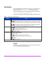
Added command line task summary table.
Page
41
19, 40
94
108
January 2002
Change
Updated WWN information to indicate that either the port WWN or
the node WNN can be used to identify a host.
Page
Multiple
Added MPE/iX, Tru64, and OpenVMS to non-native operating
system support.
20
Added HP OpenView Storage Area Manager configuration.
43
Added information on using script files to start and stop HostAgent
and OpenDIAL.
67
Added details about the software installation process.
71
Removed -f option from armdiscover command.
123
Added performance metrics table.
162
Added -cp and -t options to armsecure command.
202
Added Problem Solving chapter.
245
March 2002
Change
Changed Command View VA version to 1.04.
Added SunCluster to host port behaviors.
Page
1
150
3
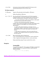
July 2002
Change
Page
Updated contents to reflect that a hardcopy of the
Command View SDM User Guide is no longer included.
14
Corrected paths to HA_DIAL_START and HA_DIAL_STOP.
67
Added host port behavior table management to the Command View
VA GUI.
104
Added host port (H1, H2) and disk enclosure port (J1, J2)
subcomponent parameters to the FRU Location Identifier values.
112
Added armdiag command used for advanced troubleshooting.
120
Added new functionality to the armdsp -p option for HP15.
131
Added -ps option and -vfp option to armdsp command for
displaying VFP settings.
Added the -b and -v options to the armdsp -i command.
Added note on host port behavior entry limitations.
144
Added new options to armhost command to aid in creating the host
port behavior table.
Added -pg and -sv options to armlog command to aid in filtering
logs. Also added -xml output option.
148
Added -P, -S, and -pv options to armmgr command.
150
Added -f option to armrecover command to perform a parity scan.
199
Updated Configure and Configure Fiber portions of CVUI menu
map.
218
Added -xml output option to logprn command.
225
Added section "Using Command View SDM on a Serial Port"
249
4
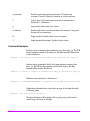
November 2002
Change
Page
Added more information on installing on OpenView SAM.
49
Added information on renaming host
69
Added information on VA 7410 firmware version numbering.
128
Added -Core option to armdiag command.
120
Added DISK-PORTS metrics to performance metrics table.
162
Added information on using the armrecover command
200
Added armshell command
206
January 2003
Change
Added VA 7110.
Removed Enterprise Intergrations as a stand-alone product. It is now
shipped with Command View SDM.
Page
Multiple
18
September 2003
Change
Added note on using the GUI through a firewall.
Added note regarding the deletion of very large LUNs potentially
causing timeouts.
Added Security Information
Added licApp, licUtil, and secadim commands
Page
87
101, 115
88
240, 242, 77
Added security information
88
Added license chapter
235
Added information on supported W2K SP and HP11.23 support
19
Added multiple IP address note for HP-UX, Windows, and Linux
45, 49, 55
5
Change
Added information on HP StorageWorks SMI-S VA
6
Page
75
contents
1
Product Description
13
HP StorageWorks Command View SDM Software 14
The Software Components 14
Event Reporting Software 15
HP StorageWorks SMI-S for Command View VA disk arrays 17
Non-Native Supported Operating Systems 20
Sources of Support Information 21
Technical Support and Manual Updates 22
HP SOFTWARE LICENSE TERMS 23
Sun Microsystems, Inc. Binary Code License Agreement 31
END-USER LICENSE AGREEMENT FOR SITRAKA INC. JCLASS
PRODUCTS 33
2
Installing Command View SDM
39
Upgrading to a Newer Version of Command View SDM 39
Command View SDM Installation Configurations 40
Installing Command View SDM on HP-UX 44
Minimum System Requirements for HP-UX 44
Installation Steps 45
Uninstalling Command View SDM from HP-UX 47
HP-UX System Support Software 48
Installing Command View SDM on Windows 49
Minimum System Requirements for Windows 49
Installation Steps 51
Setting Up the Launcher on a Remote Client 52
Uninstalling HP Command View SDM Software from Windows 54
Installing Command View SDM on Linux Red Hat 55
Minimum System Requirements for Linux Red Hat 55
7
Installation Steps 56
Uninstalling Command View SDM from Linux 58
Saving and Restoring Array Configuration Information 60
Restoring Array Configuration Information 61
Configuring Command View SDM 62
Setting up Remote Client Access 62
Configuring the Command View SDM Web Server 63
Enabling EMS Monitoring 64
Setting the System Display Variable 65
Verifying the Installation 66
Starting/Stopping HostAgent and OpenDIAL 67
Creating LUN 0 68
Adding a New Host to the Management Configuration 69
Renaming a Host 69
Details About the Command View SDM Installation Process 71
Command View SDM Architecture 71
The Installation Process 73
File Directory Structure 73
HP StorageWorks SMI-S VA (Storage Management Initiative
Specification) 75
Introduction 75
Supported Operating Systems 75
Installing SMI-S VA 75
Starting and Stopping SMI-S VA 75
Configuring SMI-S VA 76
VAProvider.hpcfg 77
Passwords 78
Configuring JAAS 79
SLP DAEMON Installer 81
Binaries Location on the Web and CD 81
Solving Installation Problems 83
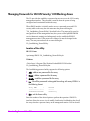
Managing Passwords for VA LUN Security/ LUN Masking Access 84
3
Using the Graphical User Interface
The GUI Components 87
Running the Command View SDM GUI 88
8
Contents
87
User Security 88
Enabling User Security 88
Configuring User Security 88
Default User Name and Password 89
Configuring User Security Using the Launcher 89
Login Screen 93
Running the Launcher from the Windows Icon 93
Running the Launcher Using a Command Line 93
Running the Management GUI Directly from a Command Line 94
Running the Launcher from a Web Browser 94
Running the Management GUI Directly from a Web Browser 95
Running the Management GUI from an OpenView SAM Management
Station 95
Using the Command View SDM GUI 96
Locating Information 96
Performing Management Tasks from the GUI 100
Checking Array Status 100
Managing Array Capacity 100
Using Secure Manager 102
Managing Host Port Behavior Table 104
4
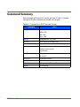
Command Line User Interface
107
Command Summary 108
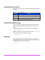
Command Syntax Conventions 110
Command View SDM man pages 110
Quick Help 110
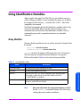
Using Identification Variables 111
Array Identifier 111
FRU Identifiers 112
Command View SDM Commands 114
armcfg 115
armcopy 118
armdiag 120
armdiscover 123
armdownload 126
armdsp 131
Contents
9
armfeature 141
armfmt 143
armhost 144
armlog 148
armmgr 150
armperf 159
armrbld 197
armrecover 199
armsecure 202
armshell 206
armtopology 209
secadmin 212
5
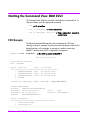
Command View SDM User Interface
215
Starting the Command View SDM CVUI 216
CVUI Example 216
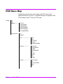
CVUI Menu Map 218
6
Array Logs
221
Managing the Size of the Log Files 223
Log Commands 224
logprn 225
logdel 228
armlog 230
About Log Files 231
Directory Structure 231
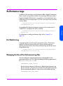
Performance Logs 233
Port Statistics Log 233
Managing the Size of the Performance Log Files 233
7
Array Licenses
235
The InstantOn License Key 235
Obtaining Permanent License Keys 236
Obtaining License Keys via the Graphical User Interface ( licApp ) 236
Obtaining License Keys via the Web 236
Obtaining License Keys via Email, Phone, or Fax 237
10
Contents
Installing License Keys 237
License Command Locations 238
Array License Commands 239
licApp 240
licUtil 242
8
Solving Problems
245
9
Using Command View SDM on a Serial Port
249
Connecting to the Array Using a Serial Port 250
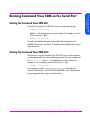
Running Command View SDM on the Serial Port 251
Starting the Command View SDM GUI 251
Starting the Command View SDM CLUI 251
Contents
11
12
Contents
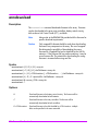
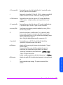
Product Description
1
HP StorageWorks Command View SDM is designed to provide storage
management for the HP StorageWorks Virtual Array products.
Command View SDM provides simple yet sophisticated device management
tools for the array. Some of the features and benefits offered by
Command View SDM include:
■ Lets you manage an unlimited number of HP virtual arrays from a
graphical user interface (GUI), command line user interface (CLUI), or
web browser.
■ The GUI uses Java technology to create a common application for all
supported operating systems
■ Provides secure device management in both direct-attach and SAN
environments.
■ Easily spans your storage system as it grows from entry level to midrange
and enterprise-wide.
■ Goes from out-of-the-box to up-and-running faster than any other device
management solution.
■ Includes a one-host license to use - add additional host licenses as your
network grows.
■ Provides web-browser support.
Product Description
13
HP StorageWorks Command View SDM Software
The Command View SDM product includes the following items:
— HP StorageWorks Command View SDM CD
— License-to-Use (1 Host)
The Software Components
The Command View SDM CD-ROM contains all the software required to
manage the HP StorageWorks Virtual Array products. The software
components include:
■ Installers - provided for Windows (NT 4.0 and 2000), HP-UX, and Linux
Red Hat.
■ Command View SDM Utilities - the underlying code, these utilities are
invoked by the user interfaces to perform all array management tasks.
■ Three User Interfaces
— Graphical User Interface (GUI) - a Java-based interface that simplifies
array management. Most management tasks can be done using the
GUI.
— Command Line User Interface (CLUI) - a full suite of commands that
provide access to the full capability of the management utilities.
— Command View SDM User Interface (CVUI) - adds a menu-based text
interface front end to the command lines. This interface provides
access to full command line functionality without requiring you to
memorize all the commands and options.
Note
The Virtual Front Panel (VFP) provides another option for
performing some of the array management and configuration
tasks. The VFP is embedded in the array controller firmware
and is not included with the other user interfaces on the CD.
■ HostAgent & OpenDIAL Services (or daemons) - these services control the
operation of the Command View SDM software. OpenDial is responsible
for discovering what arrays are visible to the host, and HostAgent
manages the server components of the software.
If Command View SDM is installed on a Windows host that is running HP
OpenView Storage Area Manager, the HostAgent and OpenDial services
14
Product Description
are not used. The HP OpenView Storage Management Server service is
used to integrate the Command View SDM software with OpenView.
Product Description
■ README file - contains updated support and installation information
■ Book files - electronic copies of the product documentation are included
for your convenience.
Event Reporting Software
The internal operation of the array is continually monitored and any
significant events are recorded. Command View SDM internal event reporting
software retrieves event information from the array and reports it to the user.
Command View SDM event software broadcasts these events to platform
dependent targets using SNMP applications with an SNMP agent to trap the
events. Command View SDM also stores these events to system log files.
Command View SDM does not support the SNMP set feature.
Device information cannot be configured from a remote host.
Note
Event targets include the following. Note that integration into some of these
applications requires the use of the Enterprise Integrations software, which is
included with Command View SDM.
■ Windows
—
—
—
—
—
—
—
—
Event Viewer
HP OpenView NNM (SNMP)
HP Top Tools (SNMP)
CA Unicenter TNG (SNMP)
BMC Patrol (SNMP)
Tivoli (SNMP)
HP EMS
Instant Support Enterprise Edition
■ Linux
— Syslog
— HP EMS
— Instant Support Enterprise Edition
■ HP-UX
— Syslog
— HP EMS
Product Description
15
—
—
—
—
—
—
HP OpenView NNM (SNMP)
HP Top Tools (SNMP)
CA Unicenter TNG (SNMP)
BMC Patrol (SNMP)
Tivoli (SNMP)
Instant Support Enterprise Edition
Events are categorized as Information, Minor Warning, Major Warning,
Serious, and Critical. These events also provide descriptions useful for
troubleshooting. A current list of events is available from the HP web site:
http://docs.hp.com/hpux/content/hardware/ems/
RemoteMonitor.htm
16
Product Description
Hewlett-Packard proudly supports the new storage standard called the
Storage Management Initiative Specification (SMI-S). Hewlett-Packard is a
contributing member of the Storage Networking Industry Association (SNIA),
which is a technical organization chartered to build seamless multi-vendor
storage management networks.
The SMI-S specification standardizes the interface for SAN management,
device control architectures and associated interfaces. It enables HewlettPackard to ultimately develop products to a single standard interface
eliminating the need for custom/manual integration of Hewlett-Packard
storage solutions into multi-vendor environments.
Hewlett Packard supports the new storage standard called the Storage
Management Initiative Specification (SMI-S). Hewlett Packard is a
contributing member to the Storage Networking Industry Association (SNIA),
which is a technical organization chartered to build seamless multi-vendor
storage management networks.
The SMI-S specification standardizes the interface for SAN management,
device control architectures and associated interfaces. The SMI-S specification
enables storage vendors to develop products to a single interface that
eliminates the need for custom integration by end users to integrate storage
devices into their environment.
To ensure that the standard has been properly implemented, SNIA has
created a series of independent third-party conformance tests that verify the
accuracy of the vendor’s implementation. Hewlett Packard was one of the first
storage vendors to successfully exit the SNIA conformance testing program.
Secondary benefits of Hewlett-Packard’s support for SMI-S are:
•
Simplification of your storage management environment enabling you to
focus on your business not managing your storage
•
Reduction in cost to deploy new storage technologies by reducing the need
for dedicated staff experts for each storage vendor’s solution
•
Increased stability of new storage technologies resulting is greater confidence
to implement these technologies
•
Minimize contention between vendors
Product Description
17
Product Description
HP StorageWorks SMI-S for Command View VA
disk arrays
•
Ability to implement larger storage infrastructures with current staff
For white papers or technical discussions on the SMI-S standard, please go
to: http://www.snia.org/smi/home.
HP Modular Storage Software Products
A full line of complementary software products are available to expand the
capability of the CommandView SDM software. These optional products are
listed in the following table. For the most up-to-date information about Modular
Storage Software products, visit the HP web site.
CommandView SDM Modular Storage Software Products
SOFTWARE PRODUCTS
CommandView SDM
Enables array configuration and management. Provides the foundation for value-added software
products. Also includes Enterprise Integrations, which integrates CommandView SDM into
network management applications BMC Patrol, HP Openview NNM for HP-UX/Windows/
Solaris, HP Openview VPO for HP-UX, and CA-Unicenter TNG.
— Software Package and 1 Host LTU* (T1086A)
Business Copy VA
Enables online data replication or LUN copying within the array for testing and backup, and
requires the same physical space to be available in the array as the LUN(s) being copied.
— Software Package and 50 GB LTU* (T1007A)
— 500 Gbyte Upgrade (T1008A)
— 1 Tbyte Upgrade (T1009A)
Secure Manager VA
Enables LUNs to be locked into a secure shared environment.
—
—
—
—
18
Software Package and 50 GB LTU* (T1003A)
500 Gbyte Upgrade (T1004A)
1 Tbyte Upgrade (T1005A)
5Tbytee Upgrade (T1006A)
Product Description
Auto Path VA for Windows 2000
Product Description
Enables I/O path fail-over in MSCS Windows 2000 environments with the benefit of I/O load
balancing in both failed and non-failed states.
— Software Package and 1 Host LTU* (T1011A)
— 1 Host Upgrade LTU (T1012A)
— 5 Host Upgrade LTU (T1013A)
Auto Path VA for Windows NT
Enables I/O path fail-over in MSCS Windows NT 4.0 environments with the benefit of I/O load
balancing in both failed and non-failed states.
— Software Package and 1 Host LTU* (T1039A)
— 1 Host Upgrade LTU (T1040A)
— 5 Host Upgrade LTU (T1041A)
Auto Path VA for HP-UX
Enables I/O path fail-over in HP-UX environments with the benefit of I/O load balancing in both
failed and non-failed states.
— Software Package and 1 Host LTU* (T1060A)
— 1 Host Upgrade LTU (T1061A)
— 5 Host Upgrade LTU (T1062A)
Auto Path VA for Linux
Enables I/O path fail-over in Linux environments with the benefit of I/O load balancing in both
failed and non-failed states.
— Software Package and 1 Host LTU* (T1044A)
— 1 Host Upgrade LTU (T1045A)
— 5 Host Upgrade LTU (T1046A)
Copy Services SMI-S VA
Enables snapshot creation/deletion/updation (asynchronous mirroring) of volumes.
— Software Package and 1 Host LTU (T1076A)
* - License to Use
Operating System Support (Native)
The Command View SDM software is supported on the following operating
systems. Because hosts running these operating systems can both access the
Product Description
19
array and also manage the array using Command View SDM, these are
referred to as “native” operating systems.
■ HP-UX*
■ Windows NT 4.0
■ Windows 2000**
■ Windows Server***
■ Linux Red Hat
■ Red Hat Linux Advanced Server
*Command View SDM 1.07 provides support for HP-UX 11.23 (IA-64) in a
non-HP OpenView environment. Command View SDM 1.07 does not support
HP-UX 11.20)
**Command View SDM 1.07 provides support for Windows 2000 SP1, SP2,
SP3 and SP4.
***Command View SDM 1.07 will now support Window Server 2003 (32-bit).
Installation instructions for each operating system are included in Chapter 2.
Non-Native Supported Operating Systems
In addition to the native operating system listed above, the HP StorageWorks
Virtual Array products are also supported on the “non-native” operating
systems listed below. Hosts running these operating systems can access data
on the array; however, Command View SDM is not supported on them.
Consequently, array management must be done from a host running one of
the supported operating systems listed above.
■ Sun Solaris
■ IBM AIX
■ Novell NetWare
■ MPE/iX (VA 7100 only)
■ HP-UX 10.20
20
Product Description
Note
Sources of Support Information
The README file included on the Command View SDM installation CD
contains important support information you should read before installing and
using the software. In addition, it is recommended that you visit the technical
support web site identified in "Technical Support and Manual Updates" on
page 22.
Product Description
21
Product Description
Command View SDM 1.07 provides support for HP-UX 11.23 (IA64) in a non-HP OpenView environment. Additionally, Command
View SDM 1.07 does not support HP-UX 11.20)
Technical Support and Manual Updates
Technical support is included with all HP StorageWorks Virtual Array
products. For details regarding support information, refer to the HP Support
Contract provided at the time you purchased the array.
For a list of the most current support phone numbers, go to the following HP
web site. This web site also has the latest version of this book available for
downloading.
http://www.hp.com/support/cvsdm
Select the contact hp link under the technical support heading for support
phone numbers.
22
Product Description
Product Description
HP SOFTWARE LICENSE TERMS
HEWLETT PACKARD COMPANY LICENSE AGREEMENT
IMPORTANT: READ CAREFULLY BEFORE USING THIS PRODUCT.
USE OF THE SOFTWARE IS SUBJECT TO THE HEWLETT-PACKARD
COMPANY ("HP") SOFTWARE LICENSE TERMS SET FORTH BELOW.
USE OF THE SOFTWARE INDICATES CUSTOMER'S ACCEPTANCE OF
THESE LICENSE TERMS. IF CUSTOMER DOES NOT ACCEPT THESE
LICENSE TERMS, CUSTOMER MUST NOT INSTALL THE SOFTWARE.
SOFTWARE PROGRAM: HP StorageWorks Command View SDM
Product/PART NUMBER: T1086A
QUANTITY of DEVICES: 1 User
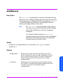
DEFINITIONS
"Software" means one or more programs capable of operating on a controller,
processor or other hardware Product ("Device") and related documentation.
Software is either a separate Product, included with another Product ("Bundled
Software"), or fixed in a Device and not removable in normal operation
("Firmware").
"Use" means storing, loading, installing, executing, or displaying Software on a
Device.
"Products" means Software and documentation that are determined by HP to be
available from HP upon receipt of Customer's order.
"Software License" means the Software license grant and general license terms
set forth herein. Each Software License has a corresponding License Fee.
"License Fee" means the fee or fees designated by HP for Use of Software.
Different License Fees may apply to particular Software if more than one
Software License is available for that Software.
Product Description
23
"Delivery" means standard HP shipping to and arrival at the receiving area at the
Ship To address specified in Customer's order.
LICENSE GRANT
1.
In return for the License Fee, HP grants Customer a non-exclusive license to
Use the object code version of the Software on the quantity of devices
specified above at any one time and in conformance with:
a. The terms set forth herein; and
b. Use restrictions and authorizations for the Software specified by HP in its
quotation, invoice or terms that accompany the Software; and
c. HP's third-party suppliers' terms that accompany the Software.
In the event of a conflict, the third-party suppliers' terms that accompany
the Software will take precedence over the Use restrictions and
authorizations specified by HP and the terms set forth herein ONLY IN
CONNECTION WITH THE CORRESPONDING THIRD PARTY SOFTWARE
(SUCH CONFLICTING THIRD PARTY TERMS, IF ANY, SHALL NOT
EXPAND HP'S DUTIES OR POTENTIAL LIABILITY UNDER THIS
AGREEMENT); and the Use restrictions and authorizations specified by
HP will take precedence over the terms set forth herein.
2.
Unless otherwise specified, in return for the applicable License Fee, HP
grants Customer a license to Use one copy of the Software on one Device at
any one time.
3.
Unless otherwise specified, all Software Licenses will be perpetual unless
terminated or transferred in accordance with the terms of this agreement.
4.
If Customer is an HP authorized reseller, Customer may sublicense the
Software to an end-user for its Use or (if applicable) sublicense the Software
to an HP authorized reseller for subsequent distribution to an end-user for its
Use. These sublicenses must incorporate the terms of this Software License
in a written sublicense agreement, which will be made available by HP upon
request. If Customer is not an HP authorized reseller, Customer may not
sublicense the Software unless otherwise agreed to by HP in writing.
Pursuant to HP’s licenses with these third-parties, HP has included the
following relevant license notices.
JAVATM2 Runtime Environment Version 1.4
24
Product Description
JAVATM2 Runtime Environment Version 1.4 is copyrighted by Sun
Product Description
Copyright © 2000-2003 Sun. All Rights Reserved.
JCLASS Products
JCLASS Products is copyrighted by Sun
Copyright © 2000-2003 Sun. All Rights Reserved.
5.
THE SOFTWARE PROVIDED HEREIN, IS PROVIDED BY HP AND BY
THIRD PARTIES, INCLUDING THE OPEN SOURCE COMMUNITY
("ANCILLARY SOFTWARE"). USE OF THE HP SOFTWARE, THE
ANCILLARY SOFTWARE, ACCOMPANYING PRINTED MATERIALS,
AND THE "ONLINE" OR ELECTRONIC DOCUMENTATION
("PRODUCT") IS CONDITIONED UPON AND LIMITED BY THE
FOLLOWING TERMS AND CONDITIONS, INCLUDING THE "AS IS
WARRANTY STATEMENT" AND THE TERMS AND CONDITIONS OF
THE ANCILLARY SOFTWARE LICENSE AGREEMENTS
("ANCILLARY SOFTWARE LICENSES"). USE OF ANCILLARY
SOFTWARE SHALL BE GOVERNED BY THE ANCILLARY
SOFTWARE LICENSE, EXCEPT THAT THE DISCLAIMER OF
WARRANTIES AND LIMITATION OF LIABILITIES PROVISIONS
CONTAINED IN THE "AS-IS WARRANTY STATEMENT" OF THIS
AGREEMENT SHALL ALSO APPLY TO SUCH ANCILLARY
SOFTWARE. HP HAS IDENTIFIEDANCILLARY SOFTWARE BY
EITHER NOTING THE ANCILLARY SOFTWARE PROVIDER'S
OWNERSHIP WITHIN EACH ANCILLARY SOFTWARE PROGRAM
FILE AND/OR BY PROVIDING INFORMATION IN THE
"ANCILLARY.TXT" FILE. THE ANCILLARY SOFTWARE LICENSES
ARE ALSO SET FORTH IN THE "ANCILLARY.TXT" FILE. BY
ACCEPTING THE TERMS AND CONDITIONS OF THIS AGREEMENT,
LICENSEE IS ALSO ACCEPTING THE TERMS AND CONDITIONS OF
EACH ANCILLARY SOFTWARE LICENSE IN THE ANCILLARY.TXT
FILE.
IF AND ONLY IF THE PRODUCT INCLUDES SOFTWARE LICENSED
UNDER THE GNU GENERAL PUBLIC LICENSE ("GPL SOFTWARE"),
LICENSEE MAY OBTAIN A COMPLETE MACHINE-READABLE COPY OF
THE GPL SOFTWARE SOURCE CODE ("GPL SOURCE CODE") BY
DOWNLOAD FROM A SITE SPECIFIED IN THE FOLLOWING HP
WEBSITE: WWW.HP.COM. UPON LICENSEE'S WRITTEN REQUEST, HP
Product Description
25
WILL PROVIDE, FOR A FEE COVERING THE COST OF DISTRIBUTION, A
COMPLETE MACHINE-READABLE COPY OF THE GPL SOURCE CODE,
BY MAIL, TO LICENSEE. INFORMATION ABOUT HOW TO MAKE A
WRITTEN REQUEST FOR GPL SOURCE CODE MAY BE FOUND AT THE
FOLLOWING WEBSITE: WWW.HP.COM.
GENERAL LICENSE TERMS
COPYRIGHT: SOFTWARE is owned and copyrighted by HP or by third-party
suppliers. Customer's Software License confers no title or ownership and is not a
sale of any rights in the Software. Third-party suppliers may protect their rights
in the Software in the event of any infringement.
RESTRICTIONS: Customer may not rent, lease, or otherwise transfer the
Software except as expressly authorized in these terms. Customer may not make
the Software available over the Internet or any other publicly accessible network
or technology. Customer may not remove any copyright, trademark, or other
proprietary notices from the Software or the media. Any and all copyrights must
be reproduced.
COPYING: Customer may not copy the Software except as expressly provided
for herein. Customer may copy the Software into the local memory or storage
device of the specified quantity of computers. Customer may not copy the
Software onto a network server or onto a company or personal intranet. Customer
may make archival or back-up copies of the Software. Customer may
permanently transfer its rights to use the Software, the Software itself including
any updates to the specified version of the Software, and the accompanying
documentation including your hard copy License Agreement, provided you
retain no copies of the Software, updates, documentation, or License Agreement,
and the recipient agrees to the License Terms.
TRANSFERABILITY: Customer's Software License is transferable subject to
HP's prior written authorization and payment to HP of any applicable fee(s).
Upon transfer of the Software License, Customer will immediately deliver all
copies of the Software to the transferee. Customer may transfer Firmware only
upon transfer of the associated Device. The transferee must agree in writing to
the terms of Customer's Software License. All Software License terms will be
binding on involuntary transferees, notice of which is hereby given. Customer's
Software License will automatically terminate upon transfer.
26
Product Description
UPGRADES: Updates, upgrades or other enhancements are available under HP
Support agreements. HP reserves the right to require additional licenses and fees
for Use of the Software on upgraded Devices.
MODIFICATION/DECOMPILING: Customer will not modify, disassemble,
reverse engineer, decompile or create derivative works of the Software without
HP's prior written consent. Where Customer has other rights under statute,
Customer will provide HP with reasonably detailed information regarding any
intended disassembly or decompilation. Customer will not decrypt the Software
unless necessary for legitimate use of the Software.
LIMITATION OF LIABILITY
Attention Notice
EXCEPT TO THE EXTENT PROHIBITED BY LOCAL LAW, IN NO EVENT
WILL HP OR ITS SUBSIDIARIES, AFFILIATES, DIRECTORS, OFFICERS,
EMPLOYEES, AGENTS OR SUPPLIERS BE LIABLE FOR DIRECT,
INDIRECT, SPECIAL, INCIDENTAL, CONSEQUENTIAL, PUNITIVE, OR
OTHER DAMAGES (INCLUDING LOST PROFIT, LOST DATA, OR
DOWNTIME COSTS), ARISING OUT OF THE USE, INABILITY TO USE,
OR THE RESULTS OF USE OF THE SOFTWARE, WHETHER BASED IN
WARRANTY, CONTRACT, TORT OR OTHER LEGAL THEORY, AND
WHETHER OR NOT HP WAS ADVISED OF THE POSSIBILITY OF SUCH
DAMAGES. THE SOFTWARE IS NOT SPECIFICALLY DESIGNED,
MANUFACTURED OR INTENDED FOR USE IN THE PLANNING,
CONSTRUCTION, MAINTENANCE, OR DIRECT OPERATION OF A
NUCLEAR FACILITY, AIRCRAFT NAVIGATION OR AIRCRAFT
COMMUNICATION SYSTEMS, AIR TRAFFIC CONTROL, DIRECT LIFE
SUPPORT MACHINES, OR WEAPONS SYSTEMS. CUSTOMER IS
SOLELY LIABLE IF THE SOFTWARE IS USED FOR THESE
Product Description
27
Product Description
TERMINATION: HP may terminate Customer's or any transferee or
sublicensee's Software License upon notice for failure to comply with any
applicable Software License terms. Immediately upon termination, the Software
and all copies of the Software will be destroyed or returned to HP. Copies of the
Software that are merged into adaptations, except for individual pieces of data in
Customer's or transferee's or sublicensee's database, will be removed and
destroyed or returned to HP. With HP's written consent, one copy of the Software
may be retained subsequent to termination for archival purposes.
APPLICATIONS. CUSTOMER WILL INDEMNIFY AND HOLD HP
HARMLESS FROM ALL LOSS, DAMAGE, EXPENSE OR LIABILITY IN
CONNECTION WITH SUCH USE. In any case, HP's entire liability under any
provision of this Software License and Express Limited Warranty shall be
limited to the greater of the amount actually paid by Customer for the Software
or U.S. $ 5.00. Customer's use of the Software is entirely at Customer's own
risk. Should the Software prove defective, Customer assumes the entire cost of
all service, repair or correction.. Some jurisdictions do not allow the exclusion or
limitation of liability for incidental or consequential damages, so the above
limitation may not apply to Customer to the extent prohibited by such local
laws.
WARRANTY: HP warrants only that the Software media will be free of
physical defects for a period of ninety (90) days from delivery.
EXCLUSIVE REMEDY: The entire liability of HP and its suppliers and
Customer's exclusive remedy for Software that does not conform to this Limited
Warranty shall be the repair or replacement of the defective media. This warranty
and remedy are subject to Customer's return of the defective media during the
warranty period to HP in the country in which Customer obtained the Software.
Attention Notice
DISCLAIMER: TO THE EXTENT ALLOWED BY LOCAL LAW, THIS
SOFTWARE IS PROVIDED TO CUSTOMER "AS IS" WITHOUT
WARRANTIES OR CONDITIONS OF ANY KIND, WHETHER ORAL OR
WRITTEN, EXPRESS OR IMPLIED. HP SPECIFICALLY DISCLAIMS ANY
IMPLIED WARRANTIES OR CONDITIONS OF MERCHANTABILITY,
SATISFACTORY QUALITY, NON-INFRINGEMENT, TITLE, ACCURACY
OF INFORMATIONAL CONTENT, AND FITNESS FOR A PARTICULAR
PURPOSE. THE ENTIRE RISK AS TO THE RESULTS AND
PERFORMANCE OF THE SOFTWARE IS ASSUMED BY CUSTOMER. NO
ORAL OR WRITTEN INFORMATION OR ADVICE GIVEN BY HP OR HP'S
AUTHORIZED REPRESENTATIVES SHALL CREATE A WARRANTY OR
AMEND THIS "AS IS" WARRANTY. Some jurisdictions do not allow
exclusions of implied warranties or conditions, so the above exclusion may not
apply to Customers to the extent prohibited by such local laws. Customer may
have other rights that vary from country to country, state to state, or province to
province.
28
Product Description
GOVERNMENT: If the Software is licensed for use in the performance of a
U.S. government prime contract or subcontract, Customer agrees that, consistent
with FAR 12.211 and 12.212, commercial computer software, computer software
documentation and technical data for commercial items are licensed under
vendor's standard commercial license.
GENERAL TERMS
ASSIGNABILITY: Customer may not assign any rights or obligations hereunder
without prior written consent from HP.
EXPORT: Customer who exports, re-exports or imports HP licensed Products,
technology or technical data purchased hereunder, assumes responsibility for
complying with applicable laws and regulations and for obtaining required export
and import authorizations. HP may suspend performance if Customer is in
violation of any applicable laws or regulations.
SEVERABILITY: If any term or provision herein is determined to be illegal or
unenforceable, the validity or enforceability of the remainder of the terms or
provisions herein will remain in full force and effect.
INTEGRATION/PRECEDENCE: These HP Software License Terms supersede
any previous communications, representations or agreements between the
parties, whether oral or written, regarding transactions hereunder. Customer's
additional or different terms and conditions will not apply. These HP Software
License Terms may not be changed except by an amendment signed by an
authorized representative of each party.
GOVERNING LAW. The validity of any of the terms of this license agreement,
as well as the rights, duties and obligations of the parties under this license
agreement, will be governed by the laws of the State of California, USA, without
Product Description
29
Product Description
NOTE: EXCEPT TO THE EXTENT ALLOWED BY LOCAL LAW, THESE
WARRANTY TERMS DO NOT EXCLUDE, RESTRICT OR MODIFY, AND
ARE IN ADDITION TO, THE MANDATORY STATUTORY RIGHTS
APPLICABLE TO THE LICENSE OF THE SOFTWARE TO CUSTOMER;
PROVIDED, HOWEVER, THAT THE CONVENTION ON CONTRACTS
FOR THE INTERNATIONAL SALE OF GOODS IS SPECIFICALLY
DISCLAIMED AND SHALL NOT GOVERN OR APPLY TO THE
SOFTWARE PROVIDED IN CONNECTION WITH THIS WARRANTY
STATEMENT.
reference to any conflict of laws or choice of law principles in the State of
California that might result in the application of the law of another jurisdiction.
© 2003 Hewlett-Packard Development Company, L.P
30
Product Description
READ THE TERMS OF THIS AGREEMENT AND ANY PROVIDED SUPPLEMENTAL LICENSE TERMS
(COLLECTIVELY "AGREEMENT") CAREFULLY BEFORE OPENING THE SOFTWAREMEDIA
PACKAGE. BY OPENING THE SOFTWARE MEDIA PACKAGE, YOU AGREE TO THE TERMS OF
THIS AGREEMENT. IF YOU ARE ACCESSING THE SOFTWARE ELECTRONICALLY, INDICATE
YOUR ACCEPTANCE OF THESE TERMS BY SELECTING THE "ACCEPT" BUTTON AT THE END OF
THIS AGREEMENT. IF YOU DO NOT AGREE TO ALL THESE TERMS, PROMPTLY RETURN THE
UNUSED SOFTWARE TO YOUR PLACE OF PURCHASE FOR A REFUND OR, IF THE SOFTWARE
IS ACCESSED ELECTRONICALLY, SELECT THE "DECLINE" BUTTON AT THE END OF THIS
AGREEMENT.
1. LICENSE TO USE. Sun grants you a non-exclusive and non-transferable license for the
internal use only of the accompanying software and documentation and any error corrections
provided by Sun (collectively "Software"), by the number of users and the class of computer
hardware for which the corresponding fee has been paid.
2. RESTRICTIONS Software is confidential and copyrighted. Title to Software and all associated
intellectual property rights is retained by Sun and/or its licensors. Except as specifically
authorized in any Supplemental License Terms, you may not make copies of Software, other than
a single copy of Software for archival purposes. Unless enforcement is prohibited by applicable
law, you may not modify, decompile, or reverse engineer Software. You acknowledge that
Software is not designed, licensed or intended for use in the design, construction, operation or
maintenance of any nuclear facility. Sun disclaims any express or implied warranty of fitness for
such uses. No right, title or interest in or to any trademark, service mark, logo or trade name of
Sun or its licensors is granted under this Agreement. "
3. LIMITED WARRANTY. Sun warrants to you that for a period of ninety (90) days from the date
of purchase, as evidenced by a copy of the receipt, the media on which Software is furnished (if
any) will be free of defects in materials and workmanship under normal use. Except for the
foregoing, Software is provided "AS IS". Your exclusive remedy and Sun's entire liability under
this limited warranty will be at Sun's option to replace Software media or refund the fee paid for
Software.
4. DISCLAIMER OF WARRANTY. UNLESS SPECIFIED IN THIS AGREEMENT, ALL EXPRESS OR
IMPLIED CONDITIONS, REPRESENTATIONS AND WARRANTIES, INCLUDING ANY IMPLIED
WARRANTY OF MERCHANTABILITY, FITNESS FOR A PARTICULAR PURPOSE OR NONINFRINGEMENT ARE DISCLAIMED, EXCEPT TO THE EXTENT THAT THESE DISCLAIMERS ARE
HELD TO BE LEGALLY INVALID.
5. LIMITATION OF LIABILITY. TO THE EXTENT NOT PROHIBITED BY LAW, IN NO EVENT WILL
SUN OR ITS LICENSORS BE LIABLE FOR ANY LOST REVENUE, PROFIT OR DATA, OR FOR
SPECIAL, INDIRECT, CONSEQUENTIAL, INCIDENTAL OR PUNITIVE DAMAGES, HOWEVER
CAUSED REGARDLESS OF THE THEORY OF LIABILITY, ARISING OUT OF OR RELATED TO THE
USE OF OR INABILITY TO USE SOFTWARE, EVEN IF SUN HAS BEEN ADVISED OF THE
POSSIBILITY OF SUCH DAMAGES. In no event will Sun's liability to you, whether in contract,
tort (including negligence), or otherwise, exceed the amount paid by you for Software under this
Agreement. The foregoing limitations will apply even if the above stated warranty fails of its
essential purpose.
Product Description
31
Product Description
Sun Microsystems, Inc. Binary Code License
Agreement
6. Termination. This Agreement is effective until terminated. You may terminate this Agreement
at any time by destroying all copies of Software. This Agreement will terminate immediately
without notice from Sun if you fail to comply with any provision of this Agreement. Upon
Termination, you must destroy all copies of Software.
7. Export Regulations. All Software and technical data delivered under this Agreement are
subject to US export control laws and may be subject to export or import regulations in other
countries. You agree to comply strictly with all such laws and regulations and acknowledge that
you have the responsibility to obtain such licenses to export, re-export, or import as may be
required after delivery to you.
8. U.S. Government Restricted Rights. If Software is being acquired by or on behalf of the U.S.
Government or by a U.S. Government prime contractor or subcontractor (at any tier), then the
Government's rights in Software and accompanying documentation will be only as set forth in
this Agreement; this is in accordance with 48 CFR 227.7201 through 227.7202-4 (for
Department of Defense (DOD) acquisitions) and with 48 CFR 2.101 and 12.212 (for non-DOD
acquisitions).
9. Governing Law. Any action related to this Agreement will be governed by California law and
controlling U.S. federal law. No choice of law rules of any jurisdiction will apply.
10. Severability. If any provision of this Agreement is held to be unenforceable, this Agreement
will remain in effect with the provision omitted, unless omission would frustrate the intent of the
parties, in which case this Agreement will immediately terminate.
11. Integration. This Agreement is the entire agreement between you and Sun relating to its
subject matter. It supersedes all prior or contemporaneous oral or written communications,
proposals, representations and warranties and prevails over any conflicting or additional terms
of any quote, order, acknowledgment, or other communication between the parties relating to its
subject matter during the term of this Agreement. No modification of this Agreement will be
binding, unless in writing and signed by an authorized representative of each party.
For inquiries please contact: Sun Microsystems, Inc. 901 San Antonio Road, Palo Alto,
California 94303
JAVATM 2 RUNTIME ENVIRONMENT VERSION 1.4 SUPPLEMENTAL
LICENSE TERMS
These supplemental license terms ("Supplemental Terms") add to or modify the terms of the
Binary Code License Agreement (collectively, the "Agreement"). Capitalized terms not defined in
these Supplemental Terms shall have the same meanings ascribed to them in the Agreement.
These Supplemental Terms shall supersede any inconsistent or conflicting terms in the Agreement,
or in any license contained within the Software.
1. License to Distribute. Subject to the terms and conditions of this Agreement, including, but not
limited to, Section 2 (Redistributables) and Section 3 (Java Technology Restrictions) of these
Supplemental Terms, Sun grants you a non-exclusive, non-transferable, limited license to
reproduce and distribute the Software in binary code form only, provided that you (i) distribute
the Software complete and unmodified, only as part of, and for the sole purpose of running your
Java applet or application ("Program") into which the Software is incorporated, (ii) do not
distribute additional software intended to replace any component(s) of the Software, (iii) do not
remove or alter any proprietary legends or notices contained in the Software, (iv) only distribute
the Program subject to a license agreement that protects Sun's interests consistent with the terms
contained in this Agreement, and (v) agree to defend and indemnify Sun and its licensors from
and against any damages, costs, ! liabilities, settlement amounts and/or expenses (including
32
Product Description
attorneys' fees) incurred in connection with any claim, lawsuit or action by any third party that
arises or results from the use or distribution of any and all Programs and/or Software.
3. Java Technology Restrictions. You may not modify the Java Platform Interface ("JPI", identified
as classes contained within the "java" package or any subpackages of the "java" package), by
creating additional classes within the JPI or otherwise causing the addition to or modification of
the classes in the JPI. In the event that you create an additional class and associated API(s) which
(i) extends the functionality of a Java platform, and (ii) is exposed to third party software
developers for the purpose of developing additional software which invokes such additional API,
you must promptly publish broadly an accurate specification for such API for free use by all
developers. You may not create, or authorize your licensees to create additional classes,
interfaces, or subpackages that are in any way identified as "java", "javax", "sun" or similar
convention as specified by Sun in any class file naming convention.
4. Trademarks and Logos. You acknowledge and agree as between you and Sun that Sun owns
the Java trademark and all Java-related trademarks, service marks, logos and other brand
designations including the Coffee Cup logo and Duke logo ("Java Marks"), and you agree to
comply with the Sun Trademark and Logo Usage Requirements currently located at http://
www.sun.com/policies/trademarks. Any use you make of the Java Marks inures to Sun's benefit.
5. Source Code. Software may contain source code that is provided solely for reference purposes
pursuant to the terms of this Agreement. Source code may not be redistributed.
6. Termination. Sun may terminate this Agreement immediately should any Software become, or
in Sun's opinion be likely to become, the subject of a claim of infringement of a patent, trade
secret, copyright or other intellectual property right.
END-USER LICENSE AGREEMENT FOR SITRAKA INC. JCLASS PRODUCTS
The following is the end user license agreement ("EULA") used on all of Sitraka Inc.'s JClass
products, other than JClass JarMaster.
IMPORTANT -- READ CAREFULLY: This Sitraka Inc. ("Sitraka") End-User License Agreement
("EULA") is a legal agreement between you (either an individual or a single entity) and Sitraka
for the Sitraka software product identified above, which computer software includes class
libraries (including source code if you have purchased it), Sun Microsystems, Inc.'s Java© Project
X Technology and may include associated media, printed materials, and "online" or electronic
documentation ("SOFTWARE"). By installing, copying, or otherwise using the SOFTWARE, you
Product Description
33
Product Description
2. Redistributables. In addition to the license granted in Paragraph 1 above, Sun grants you a
non-exclusive, non-transferable, limited license to reproduce and distribute, only as part of
Software, those files specifically identified as redistributable in the Software "README" file (the
"Redistributables") provided that: (a) you distribute the Redistributables complete and unmodified
(unless otherwise specified in the applicable README file), and only bundled as part of the
JavaTM applets and applications that you develop (the "Programs:); (b) you do not distribute
additional software intended to supersede any component(s) of the Redistributables; (c) you do
not remove or alter any proprietary legends or notices contained in or on the Redistributables;
(d) you only distribute the Redistributables pursuant to a license agreement that protects Sun's
interests consistent with the terms contained in the Agreement; and (e) you agree to defend and
indemnify Sun and its licensor! s from and against any damages, costs, liabilities, settlement
amounts and/or expenses (including attorneys' fees) incurred in connection with any claim,
lawsuit or action by any third party that arises or results from the use or distribution of any and
all Programs and/or Software.
agree to be bound by the terms of this EULA. If you do not agree to the terms of this EULA, do not
install or use the SOFTWARE; you may, however, return it to your place of purchase for a full
refund.
SOFTWARE LICENSE
The SOFTWARE is protected by copyright laws and international copyright treaties, as well as
other intellectual property laws and treaties. The SOFTWARE is licensed, not sold.
1. GRANT OF LICENSE
This EULA grants you the following rights:
a. If You Have Any Version Of A JClass Product. This license permits a single developer to
use the SOFTWARE on a single computer, subject to the restrictions in Section 3:
i) To Build Applets. Provided that applets you build are used only as an internal
component in end-user oriented user-interfaces, you may copy them to additional
computers (e.g. Web Servers), from which you may allow end-users to download,
royalty-free, the applets in the course of browsing or interacting with Web pages
you create. You are not permitted to distribute the applets in any fashion which
would promote, encourage or allow reuse or redistribution of the applet, other than
as permitted above; and
ii) To Build Stand-Alone Java© Applications. You have a royalty- free right to reproduce
and distribute the class libraries as an integral part of your application(s). You are
not permitted to expose, either directly or indirectly, any API that allows
programmatic access to the class libraries.
b. Source Code. If you have purchased the "Source Code" version of any product, you must
use reasonable efforts to maintain the confidentiality of the source code, including
ensuring that it is installed and used only on the single machine for which it is licensed,
and that it is not otherwise used or copied.
c. Definition Of Use. The SOFTWARE is "in use" on a computer when it is loaded into
temporary memory (i.e. RAM) or installed into permanent memory (e.g. hard disk, CDROM, or other storage device) of that computer, except that a copy installed on a
network server for the sole purpose of distribution to other computers is not "in use".
2. LIMITED DISTRIBUTION RIGHTS.
Your royalty-free distribution rights described in Section 1 above are granted provided that you:
(a) distribute the Applet(s) you build only in conjunction with and as an integral part of your
Web pages, and distribute the class libraries only as an integral part of your end-user,
stand-alone application;
(b) your Web pages or software product(s) are targeted at end-users, and are not a
development tool;
(c) you do not use Sitraka's name, logo or trademark to market your Web pages or
application;
(d) you include a valid copyright notice on your Web pages and software products; and
(e) you agree to indemnify, hold harmless, and defend Sitraka and its suppliers from and
against any claims or lawsuits, including attorney's fees, that arise or result from the use
or distribution of your Web pages and/or applications.
34
Product Description
3. DESCRIPTION OF OTHER RIGHTS AND LIMITATIONS.
b. Other Restrictions. You may not reverse engineer, decompile, disassemble, create
passwords for or translate the software, except to the extent such foregoing restriction is
expressly prohibited by applicable law.
c. Support Services. Sitraka may provide you with support services related to the SOFTWARE
("Support Services"). Use of Support Services is governed by the Sitraka policies and
programs described in the user manual, "online" documentation, and/or other Sitrakaprovided materials. Any supplemental software code provided to you as part of the
Support Services shall be considered part of the SOFTWARE and subject to the terms
and conditions of this EULA. With respect to technical information you provide to Sitraka
as part of the Support Services, Sitraka may use such information for its business
purposes, including for product support and development. Sitraka will not utilize such
technical information in a form that personally identifies you.
d. Termination. Without prejudice to any other rights, Sitraka may terminate this EULA if you
fail to comply with the terms and conditions of this EULA. In such event, you must destroy
all copies of the SOFTWARE and all of its component parts.
4. UPGRADES
If the SOFTWARE is labeled as an upgrade, you must be properly licensed to use a product
identified by Sitraka as being eligible for the upgrade in order to use the SOFTWARE.
SOFTWARE labeled as an upgrade replaces and/or supplements the product that formed the
basis for your eligibility for the upgrade. You may use the resulting upgraded product only in
accordance with the terms of this EULA.
5. COPYRIGHT
All title and copyrights in and to the SOFTWARE (including but not limited to any images,
photographs, animations, video, audio, music, text, and "applets" incorporated into the
SOFTWARE), the accompanying printed materials, and any copies of the SOFTWARE are
owned by Sitraka or its suppliers. Specifically, all title and copyrights in and to the Java© Project
X Technology are owned and licensed by Sun Microsystems, Inc, Copyright © Sun Microsystems,
Inc. All rights reserved.
The SOFTWARE is protected by copyright laws and international treaty provisions. Therefore,
you must treat the SOFTWARE like any other copyrighted material except that you may install the
SOFTWARE on a single computer provided you keep the original solely for backup or archival
purposes. You may not copy the printed materials accompanying the SOFTWARE.
6. DUAL-MEDIA SOFTWARE
You may receive the SOFTWARE in more than one medium. Regardless of the type or size of
medium you receive, you may use only one medium that is appropriate for your single computer.
You may not use or install the other medium on another computer. You may not loan, rent, lease,
or otherwise transfer the other medium to another user.
Product Description
35
Product Description
a. Rental. You may not rent, lease, or lend the SOFTWARE, but you may transfer the
SOFTWARE and accompanying written materials on a permanent basis provided you
retain no copies and the recipient agrees to the terms of this License Agreement. If the
SOFTWARE is an upgrade, any transfer must include the most recent upgrade and all
prior versions.
7. U.S. GOVERNMENT RESTRICTED RIGHTS
The SOFTWARE and documentation are provided with RESTRICTED RIGHTS. Use, duplication, or
disclosure by the Government is subject to restrictions as set forth in subparagraph(c)(1)(ii) of the
Rights in Technical Data and Computer Software clause at DFARS 252.227-7013 or
subparagraphs (c)(1) and (2) of the Commercial Computer Software-Restricted Rights at 48 CFR
52.227-19, as applicable. Manufacturer is Sitraka Inc., 260 King Street East, Toronto, Ontario,
Canada, M5A 4L5.
8. EXPORT RESTRICTIONS.
You agree that you do not intend to or will, directly or indirectly, export or transmit the
SOFTWARE or related documentation and technical data, or process, or service that is the direct
product of the SOFTWARE, to any country to which such export or transmission is restricted by
any applicable U.S., Canadian or other State regulation or statute, without the prior written
consent, if required, of the Bureau of Export Administration of the U.S. Department of Commerce,
or such other governmental entity as may have jurisdiction over such export or transmission.
9. MISCELLANEOUS
If you acquired this product in the United States this EULA is governed by the laws of New York
State, and the parties agree to resolve any dispute exclusively in the courts at New York City. If
you acquired this product in Canada, this EULA is governed by the laws of the Province of
Ontario, and the parties agree to resolve any dispute exclusively in the courts at Toronto.
If this product was acquired outside the United States or Canada, then local law may apply.
Should you have any questions concerning this EULA, or if you desire to contact Sitraka for any
reason, please contact the Sitraka subsidiary serving your country, or write: Sitraka Inc. Sales
Information, 260 King Street East, Toronto, Ontario, Canada, M5A 4L5.
10. LIMITED WARRANTY
LIMITED WARRANTY. Sitraka warrants that (a) the SOFTWARE will perform substantially in
accordance with the accompanying written materials for a period of ninety (90) days from the
date of receipt, and (b) any Support Services provided by Sitraka shall be substantially as
described in applicable written materials provided to you by Sitraka, and Sitraka support
engineers will make commercially reasonable efforts to solve any problem issues. Some states
and jurisdictions do not allow limitations on duration of an implied warranty, so the above
limitation may not apply to you. To the extent allowed by applicable law, implied warranties on
the SOFTWARE, if any, are limited to ninety (90) days.
CUSTOMER REMEDIES. Sitraka's and its suppliers' entire liability and your exclusive remedy
shall be, at Sitraka's option, either (a) return of the price paid, if any, or (b) repair or
replacement of the SOFTWARE that does not meet Sitraka's Limited Warranty and that is
returned to Sitraka with a copy of your receipt. This Limited Warranty is void if failure of the
SOFTWARE has resulted from accident, abuse, or misapplication. Any replacement SOFTWARE
will be warranted for the remainder of the original warranty period or thirty (30) days, whichever
is longer. Outside the United States and Canada, neither these remedies nor any product support
services offered by Sitraka are available without proof of purchase from an authorized
international source.
SPECIFIC DISCLAIMER FOR HIGH-RISK ACTIVITIES. The SOFTWARE is not designed or intended
for use in high-risk activities including, without restricting the generality of the foregoing, on-line
control of aircraft, air traffic, aircraft navigation or aircraft communications; or in the design,
construction, operation or maintenance of any nuclear facility. Sitraka and its suppliers
36
Product Description
specifically disclaim any express or implied warranty of fitness for such purposes or any other
purposes.
Product Description
NO OTHER WARRANTIES. TO THE MAXIMUM EXTENT PERMITTED BY APPLICABLE LAW,
SITRAKA AND ITS SUPPLIERS DISCLAIM ALL OTHER WARRANTIES, EITHER EXPRESS OR
IMPLIED, INCLUDING, BUT NOT LIMITED TO, IMPLIED WARRANTIES OF MERCHANTABILITY
AND FITNESS FOR A PARTICULAR PURPOSE, WITH REGARD TO THE SOFTWARE AND THE
ACCOMPANYING PRINTED MATERIALS. THIS LIMITED WARRANTY GIVES YOU SPECIFIC
LEGAL RIGHTS. YOU MAY HAVE OTHERS WHICH VARY FROM STATE/JURISDICTION TO
STATE/JURISDICTION.
11. LIMITATION OF LIABILITY.
TO THE MAXIMUM EXTENT PERMITTED BY APPLICABLE LAW, IN NO EVENT SHALL SITRAKA
OR ITS SUPPLIERS BE LIABLE FOR ANY SPECIAL, INCIDENTAL, INDIRECT, OR CONSEQUENTIAL
DAMAGES WHATSOEVER (INCLUDING, WITHOUT LIMITATION, DAMAGES FOR LOSS OF
BUSINESS PROFITS, BUSINESS INTERRUPTION, LOSS OF BUSINESS INFORMATION, OR ANY
OTHER PECUNIARY LOSS) ARISING OUT OF THE USE OF OR INABILITY TO USE THE
SOFTWARE OR THE PROVISION OF OR FAILURE TO PROVIDE SUPPORT SERVICES, EVEN IF
SITRAKA HAS BEEN ADVISED OF THE POSSIBILITY OF SUCH DAMAGES. IN ANY CASE,
SITRAKA'S AND ITS SUPPLIERS' ENTIRE LIABILITY UNDER ANY PROVISION OF THIS EULA
SHALL BE LIMITED TO THE GREATER OF THE AMOUNT ACTUALLY PAID BY YOU FOR THE
SOFTWARE OR US$5.00; PROVIDED, HOWEVER, IF YOU HAVE ENTERED INTO A SITRAKA
SUPPORT SERVICES AGREEMENT, SITRAKA'S ENTIRE LIABILITY REGARDING SUPPORT
SERVICES SHALL BE GOVERNED BY THE TERMS OF THAT AGREEMENT. BECAUSE SOME
STATES AND JURISDICTIONS DO NOT ALLOW THE EXCLUSION OR LIMITATION OF LIABILITY,
THE ABOVE LIMITATION MAY NOT APPLY TO YOU.
JCL5.0-LIC-STD-0105
Product Description
37
38
Product Description
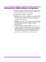
2
Installing
Command View SDM
This chapter includes procedures for installing Command View SDM on each
supported operating system. The installation process differs for each
operating system. Once the software is installed, operation of
Command View SDM is identical on all platforms.
The Command View SDM software can be installed on a host connected
directly to the array. Command View SDM can also be installed on a client
for remote management. Remote clients must be assigned permission to
manage the array by a Command View SDM host connected to the array.
If you would like some general information on the software installation
process before you begin, see "Details About the Command View SDM
Installation Process" on page 71.
Note
Can I install Command View SDM on more than one host?
The license included with the array permits you to install the
software on only one host. If you want to install the software on
additional hosts, you must purchase another license for each
host. An additional 1-host license is available as product
T1086A.
Upgrading to a Newer Version of Command View SDM
When upgrading to a newer version of Command View SDM, always
uninstall the previous version before installing the new software. This will
ensure that the software installation will complete successfully and that
Command View SDM will operate correctly.
You should also save the Command View SDM configuration files. This will
allow you to easily restore the same configuration on the new software. See
"Saving and Restoring Array Configuration Information" on page 60.
Installing Command View SDM
39
Command View SDM Installation Configurations
The installation of Command View SDM is influenced by a number of factors:
the type of hosts connected to the array, other network management tools in
use, and your strategy for local or remote management.
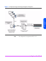
There are three typical management configurations:
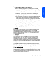
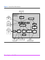
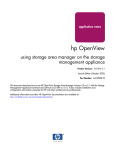
■ Native host - shown in Figure 1, this configuration is typically used when a
host accessing the array supports Command View SDM. Because array
management can be done from this host, the need for a separate
management station is eliminated.
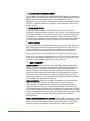
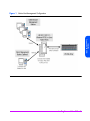
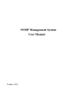
■ Non-native - shown in Figure 2, this configuration is typically used when
the hosts accessing the array do not support Command View SDM. In this
environment, Command View SDM is installed on a separate
management station.
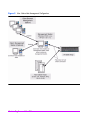
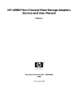
■ HP OpenView Storage Area Manager (SAM) - shown in Figure 3, this
configuration integrates Command View SDM into the OpenView SAM
management architecture. The Command View software is installed on the
SAM management station, allowing the array to be managed from the
same point as other storage resources. The SAM HostAgent must be
deployed on hosts connected to the arrays that will be managed.
40
Installing Command View SDM
Figure 1
Native Host Management Configuration
Installing
Command View SDM
Installing Command View SDM
41
Figure 2
42
Non- Native Host Management Configuration
Installing Command View SDM
Figure 3
HP OpenView Storage Area Manager Management Configuration
Installing
Command View SDM
Note
This configuration is not supported on HP-UX 11.23
Installing Command View SDM
43
Installing Command View SDM on HP-UX
The following procedure describes the steps involved in installing the
Command View SDM software on an HP-UX host or client.
Minimum System Requirements for HP-UX
Before installing the Command View SDM software, verify that the host meets
the following minimum requirements.
Host
■ HP-UX 11.0/11.11/11.23 (plus the Support Plus
Hardware Enablement Bundle, version September
2001 or later)
■ RAM: 256 Mbyte
■ Screen Resolution: 800 x 600 (for the GUI)
(Recommended 1024 X 768)
■ Video Support: 64K colors or better
■ Disk Space for Logs: 16 Mbyte per 2 months
■ Disk Space: 60 Mbyte in the /var directory (for logs)
■ Directory Space for installation:
— /opt (230Mbyte 11.00/11.11) (350Mbyte
11.23)
— /var (less than 1Mbyte for 11.00/11.11) (1.3
Mbyte for 11.23)
— /etc, /usr, / (less than 1Mbyte for 11.00/11.11/
11.23)
Locating HP-UX Patches
Support Plus Hardware/Critical Patch Bundle information can be found on
the HP-UX Support Plus CD-ROM, or on the following web page:
http://www.software.hp.com/SUPPORT_PLUS/hwe.html
The latest Java patches for HP-UX can be downloaded from the following web
site:
44
Installing Command View SDM
http://www.hp.com/products1/unix/java/infolibrary/patches.html
Selecting a Host IP Address on Systems with Multiple IP
Addresses
During installations where multiple IP addresses exist on a host (i.e. multiple
LAN cards in a single host), only one of the IP address will be entered into the /
etc/opt/sanmgr/hostagent/config/commIpAddr.txt file. If this is not the correct
address, the hostagent will not communicate with the array.
Installation Tips
— For the latest information on installing and upgrading the software,
refer to the README file on the Command View SDM Installation CD.
The README is located in the corresponding operating system
directory.
— When upgrading to a newer version of Command View SDM, always
remove the previous version before installing the new software.
— Make sure EMS hardware monitoring is installed and operating on the
host before installing Command View SDM. This will ensure that the
array is automatically added to the EMS configuration and array
events will be detected and reported.
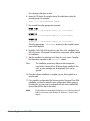
Installation Steps
1 Log onto the system as root or superuser.
2 If upgrading to a newer version of Command View SDM, save any
configuration files and remove the old software. See the following section.
3 Insert the Command View SDM software CD into the CD-ROM drive.
4 Identify the device file for the CD-ROM:
ioscan -fnCdisk
5 Create a mount point directory. For example:
mkdir /cdrom
Installing Command View SDM
45
Installing
Command View SDM
After installation, check the contents of the /etc/opt/sanmgr/hostagent/config/
commIpAddr.txt file. If the correct IP address is not shown, manually enter the
correct IP address.
Use a directory that does not exist
6 Mount the CD device file using the device file and directory from the
preceding steps. For example:
mount -o ro /dev/dsk/c0t0d0 /cdrom
7 Run swinstall using the appropriate command:
HP-UX 11.00
swinstall -s /cdrom/hpux/cvsdm_11_00_v107xx.depot
HP-UX 11.11
swinstall -s /cdrom/hpux/cvsdm_11_11_v107xx.depot
HP-UX 11.23
swinstall -s /cdrom/hpux/cvsdm_11_23_v107xx.depot
Check the appropriate /cdrom/hpux directory for the complete version
name of the depot file.
8 Highlight CMDVIEWSDM from the list, then Mark it for installation from
the Action menu. All required Command View components will be marked
for installation.
9 Start the installation by selecting Install from the Action menu. Complete
the information requested on the swinstall screens.
Note
The installation process may determine that components
required by Command View SDM are aleady installed. In this
case, an error message may be displayed, but it can be
ignored.
10 Once the software installation is complete, log out, then log back in to
reset the path.
11 If you saved the configuration files from any earlier Command View SDM
installation, use them to restore the prior configuration. Before restoring
the older files, you may want to compare them with newly installed files
(some of the old files may be the same).
Note
46
Installing Command View SDM
For installations with multiple IP addresses, see “Selecting a Host IP
Address on Systems with Multiple IP Addresses” earlier in this
chapter.
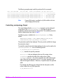
Controlling Access to Command View SDM Executable Files
Upon installation, the Command View SDM executable file permissions are
set to all users. To restrict execution of the Command View SDM executable
to root-level users only, execute the following commands as root:
chmod
chmod
chmod
chmod
500
500
600
600
/opt/sanmgr/commandview/server/sbin/*
/opt/sanmgr/commandview/client/sbin/*
/opt/sanmgr/commandview/client/sbin/*.log
/opt/sanmgr/commandview/client/sbin/*.txt
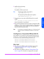
What’s Next?
refer to "Configuring Command View SDM" on page 62 for additional
configuration information.
■ If Command View SDM was installed on a client, see "Setting up Remote
Client Access" on page 62 for information on assigning client access
rights.
Note
Two Command View SDM daemons are installed on the client
that are only required on a host connected to the array. They
may be shut down on a client. To shut these daemons down,
refer to "Starting/Stopping HostAgent and OpenDIAL" on
page 67.
Uninstalling Command View SDM from HP-UX
This procedure describes uninstalling the Command View SDM software. The
existing Command View SDM software should be removed before installing a
new version of the software. The uninstall process does not automatically
delete the array log files. If you want to delete the log files, you will have to do
so manually.
1 Log onto the system as root or superuser.
2 If you are upgrading to a newer version of Command View SDM, save
any configuration files you may have customized. See "Saving and
Restoring Array Configuration Information" on page 60.
3 Display the software available for removal:
swremove
4 Select the following components for removal:
CMDVIEWSDM
Installing Command View SDM
47
Installing
Command View SDM
■ If Command View SDM was installed on a host connected to an array,
HPOVLIC
HPOVSAMDA
HPOVSAMHA
HPOVSAMJR
HPOVSAMSG
SMI-S_VA
SSLIC
5 Remove the components.
Note
If any of the components selected for removal are required by
other applications, the component will not be removed and an
error message will be displayed. This message can be ignored.
Note
If you may need the contents of the existing log files, do not
perform the next step. The log files may be useful in isolating
problems you may have been experiencing with the array.
6 Remove the log files using the following commands:
rm -fR /opt/sanmgr
rm -fR /etc/opt/sanmgr
rm -fR /var/opt/sanmgr
HP-UX System Support Software
In addition to Command View SDM, there are additional HP-UX applications
that can be used to manage and diagnose storage devices. These
applications either integrate with Command View SDM, or they provide their
own management options. These applications include:
■ System Administration Manager (SAM)
■ Support Tools Manager (STM)
■ Off-Line Diagnostic Environment (ODE)
The HP-UX Support Plus CD-ROM (June 2001 or later) includes the versions
of these applications that support the HP StorageWorks Virtual Array
products.
48
Installing Command View SDM
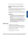
Installing Command View SDM on Windows
The following procedure describes the steps involved in installing the
Command View SDM software on a Windows NT 4.0/Windows 2000 host
or client.
Minimum System Requirements for Windows
Before installing the Command View SDM software, verify that the host meets
the following minimum requirements.
Installing
Command View SDM
Host
■ Administrator privileges (Required)
■ Windows NT 4.0 with Service Pack 6a or
■
■
■
■
■
■
Windows 2000 with Service Pack 1 or 2
500 MHz processor speed or better
256 Mbyte RAM
Screen resolution 800 x 600 (for GUI use)
(Recommended resolution: 1024 X 768)
Video support: 64K colors or better
Disk space for logs: 16 Mbyte per 2 months
Disk space:
60 Mbytes of permanent space for the application
30 Mbytes of temporary space in the Windows Temp
directory (typically C:/Temp) used during installation
Selecting a Host IP Address on Systems with Multiple IP
Addresses
During installations where multiple IP addresses exist on a host (i.e. multiple
LAN cards in a single host), only one of the IP address will be entered into the
<INSTALLDIR>\hostagent\config\commlpAddr.txt file. If this is not the correct
address, the hostagent will not communicate with the array.
After installation, check the contents of the
<INSTALLDIR>\hostagent\config\commlpAddr.txt file. If the correct IP address
is not shown, manually enter the correct IP address.
Installing Command View SDM
49
Installation Tips
— For the latest software updates, refer to the README file on the
Command View SDM CD. The README is located in the
corresponding operating system directory.
— When upgrading to a newer version of Command View SDM, always
remove the old software and save any configuration files.
HP OpenView Storage Area Manager Integration
The Command View SDM software integrates into HP OpenView Storage
Area Manager (SAM) running on a Windows management station. The
process of installing the software on OpenView SAM is the same as on a
standard WIndows environment, however you should be aware of the
following operational differences when installing on an OpenView SAM
management station:
■ The Command View software is only installed on the OpenView SAM
management station.
■ When installing Command View SDM on an OpenView SAM
management station, make sure that SAM is installed before installing
Command View SDM.
■ The OpenView SAM Host Agent must be installed on servers connected to
the arrays that will be managed.
■ When upgrading OpenView SAM, Command View SDM must be
uninstalled before performing the upgrade, and then reinstalled when the
upgrade is complete.
■ The file used to control client access on OpenView SAM is
authorizedClients.dat located in the following directory
\sanmgr\managementserver\config\.
■ The Command View HostAgent and OpenDIAL services are not used on
an OpenView SAM management station. Instead, the OpenView Storage
Management Server service is used for the Command View SDM
software.
■ OpenView SAM is supported on the following versions of Command
View:
— OVSAM 2.1 is supported with Command View 1.03/1.04
— OVSAM 2.2 is supported with Command View 1.05 and 1.06
— OVSAM 3.0 is supported with Command View 1.06
50
Installing Command View SDM
Installation Steps
1 Make sure that SAM is installed and that the SAM Host Agent has been
installed on the hosts connected to the array. See "Installing the SAM
HostAgent on OpenView SAM" below.
2 Insert the Command View SDM CD into the CD-ROM drive on the host.
3 If upgrading to a newer version of Command View SDM, save any
configuration files and remove the old software. See the following section.
4 From the Start menu, select Run.
E:\win\setup.exe
6 Follow the instructions to complete the installation.
7 If you saved the configuration files from any earlier Command View SDM
installation, use them to restore the prior configuration. Before restoring
the older files, you may want to compare them with newly installed files
(some of the old files may be the same).
Note
For installations with multiple IP addresses, see “Selecting a Host IP
Address on Systems with Multiple IP Addresses” earlier in this
chapter.
Once the installation is complete, an icon for the
Command View SDM Launcher is placed on the
desktop.
Note
If the installer finds a previous installation of Command View, it
will remove it. After the installer removes the previous version, it
will terminate the installation. You will need to run the install
program to install the new version of Command View.
Note
After uninstalling Command View SDM, check to see if HP
StorageWorks SMI-S VA is still installed. If it is still installed, you
need to uninstall HP StorageWorks SMI-S VA.
Installing Command View SDM
51
Installing
Command View SDM
5 Enter the letter of your CD-ROM drive, followed by win\setup.exe. For
example, if your CD-ROM drive is “E”, enter:
Installing the SAM HostAgent on OpenView SAM
When installing the Command View SDM software in a SAM environment,
the SAM Host Agent must be installed on hosts connected to the arrays that
will be managed. The SAM Host Agent must be installed and running on a
host to allow the SAM management client to detect and manage the array .
1 Launch the SAM GUI.
2 Select Tools > Manage Host Agent > Install Host Agent Software
Refer to the SAM on-line help for more information on installing the host
agent.
What’s Next?
■ If Command View SDM was installed on a host connected to an array,
refer to "Configuring Command View SDM" on page 62 for additional
configuration information.
■ If Command View SDM was installed on a client, continue with "Setting Up
the Launcher on a Remote Client" on page 52.
Note
Two Command View SDM daemons are installed on the client
that are only required on a host connected to the array. They
may be shut down on a client. To shut these daemons down,
refer to "Starting/Stopping HostAgent and OpenDIAL" on
page 67.
Setting Up the Launcher on a Remote Client
After installing Command View SDM on a client management station, you
must identify the host you want the Launcher to connect to. This will be a host
running Command View SDM and connected to the array(s) you want to
manage. The Launcher properties on the client must be modified to identify
the desired host.
Note
52
Installing Command View SDM
It is not necessary to perform this procedure if
Command View SDM has been installed on a client being used
for Instant Support Enterprise Edition.
1 Right click on the Command View SDM Launcher icon on the client desk
top.
2 Select Properties >> Short Cut
3 In the Target: window, append a space and the host identification to the
end of the path displayed. The host can be identified by either its DNS
name or IP address. In the following figure, the IP address 10.62.126.238
is added to the target path.
4 Click OK.
Installing
Command View SDM
Add the IP address
or the DNS name of
the CommandView
host
Note
- To manage an array from a remote client, the client must be
granted access by the Command View SDM host the Launcher
is connecting to. See "Setting up Remote Client Access" on
page 62 for more information.
- You can create additional Launcher icons connecting to
different Command View SDM hosts by right clicking on the
Launcher icon and selecting Create Shortcut. This will create a
duplicate of the existing icon, which you can then modify to
connect to a different host.
Installing Command View SDM
53
Uninstalling HP Command View SDM Software from Windows
This procedure describes uninstalling the Command View SDM software. The
existing Command View SDM software should be removed before installing a
new version of the software. The uninstall process does not automatically
delete the array log files. If you want to delete the log files, you will have to do
so manually.
1 If you are upgrading to a newer version of Command View SDM, save
any configuration files you may have customized. See "Saving and
Restoring Array Configuration Information" on page 60.
2 Close OpenView SAM if uninstalling on a SAM management station.
3 Select Start >> Settings >> Control Panel >> Add/Remove Programs
4 Select hp command view from the list of applications, and then click Add/
Remove....
Follow the screens to uninstall Command View SDM.
Note
If there has been a problem with the software or the array, the
logs should be retained and used to reference for
troubleshooting. If you are certain you will not need to access
the logs, they can be removed.
5 To remove the logs files, delete the following folder:
\sanmgr\commandview\server\logs
6 Reboot the system when the software has been removed.
54
Installing Command View SDM
Installing Command View SDM on Linux Red Hat
The following procedure describes the steps involved in installing the
Command View SDM software on a Linux Red Hat.
Minimum System Requirements for Linux Red Hat
Before installing the Command View SDM software, verify that the host meets
the following minimum requirements.
■ Red Hat Linux 7.1 with kernel 2.4.2 (plus patches, see web
Installing
Command View SDM
Host
site mentioned below)
■ Intel Pentium III 500 MHz processor
■ RAM: 256 Mbyte
■ Video Resolution: 800x600 (for GUI)
(Recommended 1024 X 768)
■ Video Support: 64K colors or better
■ Disk Space for Logs: 16 Mbyte per 2 months
■ Disk Space: 60 Mbyte
Where to Get the Latest Linux Information
For the most current supported Linux Kernel version and required patches for
Command View SDM, refer to the web documents, “Kernel Configuration”
and “Linux Tips”. These documents and all the latest information can be found
in the Using Your Product section of the following HP support web site:
http://www.hp.com/support/cvsdm
Selecting a Host IP Address on Systems with Multiple IP
Addresses
During installations where multiple IP addresses exist on a host (i.e. multiple
LAN cards in a single host), only one of the IP address will be entered into the /
etc/opt/sanmgr/hostagent/config/commIpAddr.txt file. If this is not the correct
address, the hostagent will not communicate with the array.
Installing Command View SDM
55
After installation, check the contents of the /etc/opt/sanmgr/hostagent/config/
commIpAddr.txt file. If the correct IP address is not shown, manually enter the
correct IP address.
Installation Tips.
— For the latest software updates, refer to the README file on the
HP StorageWorks Command View SDM CD. The README is located
in the corresponding operating system directory.
— When upgrading to a newer version of Command View SDM, always
remove the previous version before installing the new software.
— Before installing Command View SDM, verify that the timezone system
environmental variable, TZ, is properly set. If the TZ variable is not
properly set before installation, the system logs may have inconsistent
date stamps. If this should occur, set the TZ variable, then stop and
restart HostAgent.
Installation Steps
Installation procedures for Command View SDM on Linux Red Hat consists of
a set of shell scripts and rpm files that customize and install the necessary
software. Prior to installing the software, the Linux Kernel must be updated
using the Kernel Configuration document available on the support web site.
1 Log on as root or superuser.
2 If upgrading to a newer version of Command View SDM, remove the old
software and save any configuration files. See the following section.
3 Create a directory for the software. For example:
mkdir /tmp/cmdview
4 Insert the Command View SDM software CD into the CD-ROM drive.
5 If necessary mount the CD device file. For example:
mount /dev/cdrom /mnt/cdrom
6 Copy the contents of the CD (or download from the web) into the directory
created in step 3. For example:
cp -pr /mnt/cdrom/linux /tmp/cmdview
7 Change directories to the /linux install directory by entering:
cd /tmp/cmdview/linux
56
Installing Command View SDM
8 Install the software by entering:
install_cmdview
The installation will take several minutes.
Note
The Host Agent installer writes a log file to
/tmp/SanMgrInstall.log
The Command View SDM installer writes a log file to
/tmp/CommandViewInstall.log
export PATH=$PATH:/opt/sanmgr/commandview/client/sbin
Log out, then log back in to reset the path.
10 If you saved the configuration files from any earlier Command View SDM
installation, use them to restore the original configuration. Before restoring
the older files, you may want to compare them with newly installed files
(some of the old files may be the same).
Note
For installations with multiple IP addresses, see “Selecting a Host IP
Address on Systems with Multiple IP Addresses” earlier in this
chapter.
Controlling Access to Command View SDM Executable Files
Upon installation, the Command View SDM executable file permissions are
set to all users. To restrict execution of the Command View SDM executable
to root-level users only, execute the following commands as root:
chmod
chmod
chmod
chmod
500
500
600
600
/opt/sanmgr/commandview/server/sbin/*
/opt/sanmgr/commandview/client/sbin/*
/opt/sanmgr/commandview/client/sbin/*.log
/opt/sanmgr/commandview/client/sbin/*.txt
What’s Next?
■ If the software was installed on a host connected to an array, refer to
"Configuring Command View SDM" on page 62 for additional
configuration information.
■ If the software was installed on a client, see "Setting up Remote Client
Access" on page 62 for information on assigning client access rights.
Installing Command View SDM
57
Installing
Command View SDM
9 For convenience you may want to add the following line to your path
variable:
Note
Two Command View SDM daemons are installed on the client
that are only required on the host connected to the array. They
may be shut down on a client. To shut down these daemons,
refer to "Starting/Stopping HostAgent and OpenDIAL" on
page 67.
Uninstalling Command View SDM from Linux
This procedure describes uninstalling the Command View SDM software. The
existing Command View SDM software should be uninstalled before installing
a new version of the software. The uninstall process does not automatically
delete the array log files. If you want to delete the log files, you will have to do
so manually.
Note
The 1.07 version of the Linux installer will not correctly remove
earlier versions of the Command View software. Previously
installed versions on Linux should be uninstalled using the
uninstaller for that version of command view. If the 1.07
uninstaller is used, the following steps may be taken to ensure
all unnecessary files are removed:
rm -fR /opt/sanmgr/hostagent
rm -fR /var/opt/sanmgr/hostagent
rm -fR /etc/opt/sanmgr/hostagent
1 If you are upgrading to a newer version of Command View SDM, save
any configuration files you may have customized. See "Saving and
Restoring Array Configuration Information" on page 60.
2 Uninstall the Command View SDM software:
uninstall_cmdview
Note
If there has been a problem with the software or the array, the
logs should be retained and used to reference for
troubleshooting. If you are certain you will not need to access
the logs, they can be removed.
3 To remove the logs, enter the following three commands:
rm -fR /opt/sanmgr
rm -fR /etc/opt/sanmgr
rm -fR /var/opt/sanmgr
58
Installing Command View SDM
If you are re-installing Command View SDM software, perform the
installation procedures described under "Installing Command View SDM on
Linux Red Hat" on page 55.
Installing
Command View SDM
Installing Command View SDM
59
Saving and Restoring Array Configuration
Information
Several configuration files are used to customize the operation of
Command View SDM. Because these files allow you to easily replicate or
restore the configuration of your array, it is recommended that you maintain
copies of these files. This is particularly important if you plan to upgrade to a
newer version of Command View SDM. After the new software has been
installed, these files can be copied into the newly installed files to recreate the
desired operating configuration. Before restoring the older files, you may
want to compare them with newly installed files (some of the old files may be
the same).
Note
To prevent the configuration files from being deleted when you
uninstall the existing Command View SDM software to upgrade
to a newer version, make sure the copies are in a location
outside the Command View SDM installation path.
There are three configuration files that should be saved:
HP-UX and Linux
/opt/sanmgr/commandview/server/config/PanConfigParams.txt
/opt/sanmgr/commandview/server/config/ContactInfo.txt
/opt/sanmgr/hostagent/config/access.dat
/opt/sanmgr/hostagent/config/commIpAddr.txt
Windows
\Program Files\Hewlett-Packard\sanmgr\commandview\server\config\PanConfigParams.txt
\Program Files\Hewlett-Packard\sanmgr\commandview\server\config\ContactInfo.txt
\Program Files\Hewlett-Packard\sanmgr\hostagent\config\access.dat
Windows - HP OpenView Storage Area Manager
\Program Files\Hewlett-Packard\sanmgr\commandview\server\config\PanConfigParams.txt
\Program Files\Hewlett-Packard\sanmgr\commandview\server\config\ContactInfo.txt
\Program Files\Hewlett-Packard\sanmgr\managementserver\config\authorizedClients.dat
In addition, if you have downloaded any firmware update files stored within
the Command View SDM installation path, and would like to save them, copy
them to a temporary directory and restore after installation. Firmware file can
60
Installing Command View SDM
be identified by the .frm extension and are typically located in the
..\commandview\client\sbin directory.
Should I Save the Host Port Behavior and Secure Manager Tables?
The host port behavior table and the Secure Manger table are maintained in
the array and should not be impacted by the installation of a new version of
Command View SDM. However, for added security you may want to
consider saving copies of the LUN security table file and the host port
behavior table file. If necessary, these files can be used to replicate or restore
security and port behavior on the array.
Installing
Command View SDM
Restoring Array Configuration Information
After Command View SDM has been installed on the host, the saved
configuration can be restored as follows:
1 Replace files access.dat and ContactInfo.txt with the saved
versions of the files.
2 Update the PanConfigParams.txt file using one of the following
steps:
a If you have upgraded to a new version of Command View SDM, the
newer version will include configuration settings that will be erased if
you replace the new PanConfigParams.txt file with the older
saved file. Instead, open both files in a text editor, identify any
configuration settings you have changed in the saved file, update the
new file with the changes., and save the updated file.
b If you are replicating the configuration on another host running the
same version of Command View SDM, simply replace the existing
PanConfigParams.txt with the saved version.
3 Restart HostAgent and OpenDIAL to invoke the new configuration. See
"Starting/Stopping HostAgent and OpenDIAL" on page 67.
Installing Command View SDM
61
Configuring Command View SDM
Once installed, it may be necessary to configure the operation of
Command View SDM. Configuration is required to perform the following
tasks:
■ Setting up remote client access
■ Configuring the Command View SDM web browser
■ Enabling EMS if necessary (HP-UX only)
Setting up Remote Client Access
When using a remote client to manage arrays, the client must be granted
access rights by the Command View SDM host connected to the array. This
includes clients running Command View SDM, and web browser clients.
Access rights are managed using a special access file which is maintained on
the Command View SDM host connected to the array. This file contains the IP
addresses of clients that are allowed to manage any array connected to the
host.
The following files are used to control client access:
■ access.dat - standard installation
■ authorizedClients.dat - HP OpenView Storage Area Manager
(SAM) installation
Note
By default the configuration file contains a value of
“127.0.0.1”. This localhost entry is required for
Command View SDM host operation and must remain in the
file.
1 On the Command View SDM host connected to the array, open the
configuration file in a text editor. The file is located in the following
directory:
HP-UX and Linux: /opt/sanmgr/hostagent/config/
Windows: \sanmgr\hostagent\config\
HP OpenView SAM: \sanmgr\managementserver\config\
2 Add the IP address for each client requiring access to the arrays
connected to the host. Single client IP addresses can be added, or a range
of IP addresses can be added using the wild card “*”. For example;
10.62.128.* grants access to any client on subnet 128. The use of
62
Installing Command View SDM
wildcards is recommended when connecting from clients configured for
dynamic host configuration protocol (DHCP).
3 Save the configuration file.
Removing a Client
Use the above procedure to remove a host you no longer want to have
access. When removing clients it is necessary to stop and restart the
HostAgent to implement the change. See "Starting/Stopping HostAgent and
OpenDIAL" on page 67.
The Command View SDM software includes its own web server, which is
installed along with the other software components. By default, the web server
is enabled on port 4096. If you need to disable the web server or change its
port, you can do so using the following procedures.
Disabling the Web Server
By default, the Command View SDM web server is enabled to provide remote
management capability. If remote access via the web is a security concern,
the web server can be disabled.
1 On the Command View SDM host, open the web server configuration file,
PanConfigParams.txt, in a text editor. The configuration file is located
in the following directory:
HP-UX or Linux
/opt/sanmgr/commandview/server/config/
Windows
<drive>:\sanmgr\commandview\server\config\
2 Disable the web server by modifying the web server entry as follows:
WEBSERVER_ENABLED=false
Should you need to re-enable the web server, set the value to “true”.
Changing the Web Server Port
By default, the Command View SDM web server listens for http requests on
port 4096. If this port is not available on your system, you can specify a
different port. The port is specified in the following parameter in the
configuration file PanConfigParams.txt:
Installing Command View SDM
63
Installing
Command View SDM
Configuring the Command View SDM Web Server
WEBSERVER_PORT=4096
Change the value to an available port number.
Restarting the HostAgent Service
After making changes to the configuration PanConfigParams.txt file, you
must stop and restart the HostAgent service on the server. For information on
performing this operation, refer to "Starting/Stopping HostAgent and
OpenDIAL" on page 67.
Note
HP OpenView SAM Implementation
On HP OpenView SAM you must stop and restart the HP
OpenView Storage Management Server service, not HostAgent.
This is done from the Services dialog accessed from the Control
Panel.
Enabling EMS Monitoring
If EMS monitoring is running on an HP-UX host when Command View SDM is
installed, the array(s) will be automatically configured into the event
monitoring. In this situation the following steps do not need to be performed.
It will be necessary to manually enable EMS if Command View SDM has been
installed in the following environments:
— Command View SDM is installed on a Windows or Linux host that will
be communicating with an HP-UX host running EMS.
— Command View SDM is installed on an HP-UX host that is not running
EMS, but will be communicating with an HP-UX host that is running
EMS.
— EMS monitoring is installed on an HP-UX host after
Command View SDM has been installed.
To manually enable EMS, perform the following steps:
1 On an HP-UX host which is running EMS, perform the following steps. On
all other hosts, go to step 2.
a Open the following file in a text editor:
/var/stm/config/tools/monitor/RemoteMonitor.cfg
b Edit the entry for DISK_ARRAY to read as follows:
DISK_ARRAY ENABLE
64
Installing Command View SDM
c
Save the file.
d Continue with step 2.
2 Open the following file in a text editor:
/opt/sanmgr/commandview/server/config/PanConfigParams.txt
3 Edit the following entry to read as follows:
EMS_HOST=hostname
hostname is the name of the host running EMS
4 Save the file.
Installing
Command View SDM
Setting the System Display Variable
When launching the GUI under HP-UX or Linux, the system environmental
variable DISPLAY must be set to the system you are logged on to. In most
cases, this variable is set by the system to the current system at logon. To
verify this variable is set, type:
echo $DISPLAY
The response should be:
<your_current_system_alias>:0.0
If the DISPLAY variable is not set, the Command View SDM software will
throw a Java exception. If this occurs, set the DISPLAY variable by typing:
export DISPLAY=<your_current_system_alias>:0.0
If you are remotely logging onto the system, you must give the Remote system
access to your local system by typing on the local system prior to login:
xhost +<remote_system_alias>
If the alias of the remote system is not recognized by the local system, you
may need to use the full remote system name or IP address.
Installing Command View SDM
65
Verifying the Installation
You can easily verify the success of the Command View SDM software
installation using the following steps.
1 Perform a hardware scan from the host connected to the array to ensure
that the host can see the array. On an HP-UX host, this is done using the
ioscan -fnkdisk command.
2 From a command line on the host or client on which you have installed the
software, enter the following command:
armdsp -i <hostname>
<hostname> identifies the remote host for which information will be
displayed, and is required only when running the command on a client.
3 View the output displayed. It should include an entry similar to the
following for each array connected to the host.
Serial Number:00SG04990114
Alias Name:blue
Device Path:/dev/rscsi/c30t7d0
World Wide Name:50060b00000921d0
Product ID:HP-A6188A
Unique ID:HPA6188A00SG04990114
Note
66
Installing Command View SDM
If the anticipated output is not displayed, a problem may have
occurred during installation. See "Solving Problems" on
page 245 for help in isolating and solving the problem.
Starting/Stopping HostAgent and OpenDIAL
The HostAgent and OpenDIAL services (or daemons) are installed with
Command View SDM. These services are started automatically during
installation and any time the host is restarted. Both services must be running
on the host for Command View SDM to operate. If these services are not
running, they must be started manually. HostAgent and OpenDIAL are not
needed on a remote Command View SDM client and can be stopped.
To start or stop HostAgent and OpenDIAL you must login as root or superuser
(for HP-UX/Linux) or have Administrator Privileges (for Windows).
Installing
Command View SDM
HP-UX and Linux
Individual scripts are used to start or stop both services.
■ To stop HostAgent and OpenDIAL, enter the following command:
/opt/sanmgr/commandview/client/sbin/HA_Dial_Stop
■ To start HostAgent and OpenDIAL, enter the following command:
/opt/sanmgr/commandview/client/sbin/HA_Dial_Start
Windows NT 4.0 and 2000
Note
If Command View SDM is installed on an HP OpenView SAM
management station, the HostAgent and OpenDial services are
not used. The HP OpenView Storage Management Server
service is used to integrate the Command View SDM software
with Storage Area Manager. This is the service you must stop/
start in this environment.
Although it is possible to start or stop HostAgent and OpenDIAL from the
Services dialog, it is recommended that you use the script files described
below. This will ensure that the services are stopped and started in the proper
order.
■ To stop HostAgent and OpenDIAL, enter the following from a command
prompt:
<drive>:\Program Files\Hewlett-Packard\sanmgr\commandview\client\sbin\HA_Dial_Stop
Installing Command View SDM
67
■ To start HostAgent and OpenDIAL, enter the following from a command
prompt:
<drive>:\Program Files\Hewlett-Packard\sanmgr\commandview\client\sbin\HA_Dial_Start
Creating LUN 0
Many operating systems rely on the presence of LUN 0 to establish a
communication path to all LUNs on the array. Consequently, it is
recommended that the array always have LUN 0 present.
When LUN 0 is created, the array automatically creates an entry in the LUN
security table granting Write & Configure access to all hosts. This entry
ensures that all Command View SDM hosts will be able to manage the array.
It is recommended that this entry not be deleted from the table.
Because all hosts will have access to LUN 0, you may want to limit its size (10
MB) and not use it to store any critical data.
68
Installing Command View SDM
Adding a New Host to the Management
Configuration
When adding a new host to your system, you will need to take the necessary
steps to ensure the host can access the array. There are two steps to perform:
1 If the host does not use the default controller host port behavior, the host
will have to be added to the host port behavior table. See "Creating the
Host Port Behavior Table" on page 146 for information on performing this
task.
Renaming a Host
If it becomes necessary to rename a host, the original host name must be
removed from the host device database maintained by Command View. This
is necessary to avoid the same arrays being displayed on the new host name
and also on the old host name.
1 Run the following command to remove database entries for the existing
host name:
armdiscover [managementhost] [-h hostname] -delete
Replace hostname with the current hostname. See "armdiscover" on
page 123 for more information on using this command.
Note
If the host has been renamed and added to the database before
removing the original host name, the above command can also
be used to remove the original host name entries. If this does
not produce the desired results, it will be necessary to delete
and rebuild the database as described in the following section.
Installing Command View SDM
69
Installing
Command View SDM
2 If LUN security is being used, the host will have to be granted access to the
desired LUNs on the array. This is done by updating the LUN security
table on the array. For information on managing LUN security, refer to the
HP StorageWorks Secure Manager User Guide included with the Secure
Manager Software Media Kit (T1003A).
2 When the host name has been changed and DNS is set up to correctly
report the new hostname/IP address association, run the following
command:
armdiscover [managementhost] [-h devicehost]
The armdiscover process will detect the new host name and add it and its
associated arrays to the database.
Deleting and Rebuilding the Device Database
In some situations it may be necessary to delete and rebuild the device
database. This may be necessary if the host has been renamed and added to
the database before removing the original host.
1 Stop the HostAgent and OpenDial services as described in "Starting/
Stopping HostAgent and OpenDIAL" on page 67.
2 Delete or rename the current device database file (DeviceDBFile). The file
is located in the following directories:
HP-UX or Linux
/opt/sanmgr/commandview/server/data/
Windows
<drive>:\sanmgr\commandview\server\data\
3 Restart the HostAgent and OpenDial services as described in "Starting/
Stopping HostAgent and OpenDIAL" on page 67.
4 Run the following command to rebuild the database:
armdiscover [managementhost] -h [devicehost]
70
Installing Command View SDM
Details About the Command View SDM Installation
Process
This section describes in more detail the Command View SDM installation
process. It is not essential that you read this material to install the software
successfully. It is provided for those who have a desire to understand what is
going on behind the scenes. It may also help you solve any problems that
occur during the installation.
Understanding the architecture of the Command View SDM software
components should help you understand the installation and interaction of the
various components.
The major components is the Command View SDM software are shown in
Figure 4. The integration with other components is also shown.
Command View SDM White Paper
A white paper describing the operation of Command View SDM in more
detail can be downloaded from the following web site:
http://www.hp.com/products1/storage/products/disk_arrays/
modular/commandview/infolibrary/index.html
Installing Command View SDM
71
Installing
Command View SDM
Command View SDM Architecture
Figure 4
Command View SDM Architecture
Web Browser
HP-UX
Integration
Command View
Component
Architecture
CVSDM
Web Server
SAM
STM
Storage
Management
GUI
HP
OpenView
Storage Area
Manager
CLUI
Launcher
CVUI
Device
Database
Device Object
armdiscover
System
Management
HP OpenView
NNM
Top Tools
CA
SNMP
Agent
Events
Service
Logging
Service
SCSI Gateway
Host Agent
Log
Database
NT Event
Viewer
72
Installing Command View SDM
EMS
syslog
Storage Device
Open
DIAL
The Installation Process
The following steps identify the main tasks performed during the installation of
the software.
1 The installer creates the directory structure on the host and copies the
Command View SDM files to the appropriate folders.
2 The OpenDIAL and HostAgent services start, which in turn launch the
server components - SCSI Gateway, Logging Service, etc.
3 The armdiscover process is initiated, which causes OpenDIAL to do a
discovery of all arrays connected to the host.
5 When all arrays are discovered, the logging service is enabled and it
begins collecting log entries for the discovered arrays.
6 When the Launcher is run, it retrieves device information from the device
data to determine what arrays are connected. The Launcher then accesses
each array to determine its status and displays the appropriate icon for
each array.
File Directory Structure
During the installation a directory structure is created on the host for the
Command View SDM files. The main directory structure is listed below.
HP-UX and Linux Directories
The following directories are created when installing Command View SDM on
an HP-UX or Linux host. Files are split between /opt/sanmgr, /etc/opt/
sanmgr, and /var/opt/sanmgr
/opt/sanmgr
/opt/sanmgr/jre/bin
/opt/sanmgr/jre/lib
/opt/sanmgr/hostagent/sbin
/opt/sanmgr/hostagent/config > /etc/opt/sanmgr/hostagent/
config
/opt/sanmgr/hostagent/data > /var/opt/sanmgr/hostagent/
data
/opt/sanmgr/hostagent/log > /var/opt/sanmgr/hostagent/log
Installing Command View SDM
73
Installing
Command View SDM
4 The results of the discovery are stored in the device database files used by
other components. The contents of the database files are used to populate
the Launcher, and are returned in response to an armdsp -i command.
/opt/sanmgr/commandview/client/config
/opt/sanmgr/commandview/client/sbin
/opt/sanmgr/commandview/server/config > /etc/opt/sanmgr/
commandview/server/config
/opt/sanmgr/commandview/server/data > /var/opt/sanmgr/
commandview/server/data
/opt/sanmgr/commandview/server/logs > /var/opt/sanmgr/
commandview/server/logs
/opt/sanmgr/SMI-S/...
/opt/sanmgr/cssi/...
Windows Directories
The following directories are created when installing Command View SDM on
a Windows host. Note that some directories differ when installing on an
HP OpenView Storage Area Manager host.
\Program
\Program
\Program
\Program
\Program
\Program
\Program
\Program
Files\Hewlett-Packard\sanmgr
Files\Hewlett-Packard\sanmgr\jre\bin
Files\Hewlett-Packard\sanmgr\jre\lib
Files\Hewlett-Packard\sanmgr\commandview\client\config
Files\Hewlett-Packard\sanmgr\commandview\client\sbin
Files\Hewlett-Packard\sanmgr\commandview\server\config
Files\Hewlett-Packard\sanmgr\commandview\server\data
Files\Hewlett-Packard\sanmgr\commandview\server\logs
Standard Install with HostAgent and OpenDIAL
\Program
\Program
\Program
\Program
Files\Hewlett-Packard\sanmgr\hostagent\sbin
Files\Hewlett-Packard\sanmgr\hostagent\config
Files\Hewlett-Packard\sanmgr\hostagent\data
Files\Hewlett-Packard\sanmgr\hostagent\log
Install with HP OpenView Storage Area Manager (SAM)
\Program
\Program
\Program
\Program
74
Files\Hewlett-Packard\sanmgr\managementserver\sbin
Files\Hewlett-Packard\sanmgr\managementserver\config
Files\Hewlett-Packard\sanmgr\managementserver\data
Files\Hewlett-Packard\sanmgr\managementserver\logs
Installing Command View SDM
HP StorageWorks SMI-S VA (Storage Management
Initiative Specification)
Introduction
HP StorageWorks SMI-S VA provides the Web-Based Enterprise Management
(WBEM) interface for the management of HP StorageWorks VA arrays. SMI-S
VA is a component of Command View SDM and runs as a service daemon. To
start and stop SMI-S VA, see “SLP DAEMON Installer” later in this chapter.
Supported Operating Systems
SMI-S VA v1.02.02 is supported on the following operating systems;
■ HP-UX versions 11.0, 11.11, 11.23
■ Windows 2K SP1 or above
■ Windows NT SP6a or above
■ Windows Server 2003 (32-bit)
■ Red Hat Linux 7.1 (kernel 2.4.2)
■ Red Hat Advanced Server 2.1
Installing SMI-S VA
HP StorageWorks SMI-S VA is installed automatically when the HP
StorageWorks Command View SDM software is installed.
Starting and Stopping SMI-S VA
Windows
The display name of the service is hp StorageWorks SMI-S CIMOM
Installing Command View SDM
75
Installing
Command View SDM
This document section procedures for configuring and installing SMI-S VA for
HP StorageWorks Command View SDM. SMI-S VA v1.02.02 supports
Command View SDM 1.07 (minimum version). The recommended version is
v1.07.
(Service Name hpSMISCIMOM). The service is stopped and started by
selecting:
Control Panel > Administrative Tools > Services (for Windows 2000 and Server
2003)
Control Panel > Services (for Windows NT)
HP-UX and Linux
The name of SMI-S VA daemon is hpSMISCIMOM. The daemon can be started
by running the script SMIS_trigger located in the /opt/sanmgr/ SMI-S/directory
with the start option. The SMIS_trigger also supports restart of the service.
$ SMIS_trigger start
The daemon can be stopped by running the script SMIS_trigger with the stop
option.
$ SMIS_trigger stop
Configuring SMI-S VA
The set of configuration files you need to modify are:
■ cim.properties: CIMOM related parameters for enabling SSL, JAAS, etc.
■ VAProvider.hpcfg: The provider configuration parameters.
■ Passwords: The user names and passwords for the authentication of the
clients connecting to the CIMOM server.
■ JAAS.policy: Used for configuring an access control list.
Configuration parameters appear in the sections below. After changing any of the
configuration parameters, be sure to restart the hpSMISCIMOM service.
76
Installing Command View SDM
Table 1
cim.properties
Field
EnableBasicAuthorization
("true" or "false")
EnableCompleteAuthorization
("true" or "false")
EnableSSL
Purpose
Set this to "true" to indicate that you want the
basic level of authentication and authorization.
Set this to "true" to indicate that you want
complete authentication and authorization. Each
command needs to be authorized before it can be
executed. If EnableCompleteAuthorization is set to
"true," then the value of EnableBasicAuthorization
is ignored.
Set this to "true" to enable SSL
Installing
Command View SDM
("true" or "false")
VAProvider.hpcfg
For Windows:
Location: <DriveLetter:\>Program Files\Hewlett-Packard\SMIS\cimom\VAProvider.hpcfg
For HP-UX and Linux:
Location: /opt/sanmgr/SMI-S/VAProvider.hpcfg
VAProvider.hpcfg Syntax: <provider class>; <cycle wait time in seconds>;
<server host>; <event periodicity>; <Debug flag>; <NameSpace>; <cleanup
frequency>
The values of the parameters described in Table 2 should be configured before
managing VA arrays using HP StorageWorks SMI-S VA. A restart of the VA
provider service (hpSMISCIMOM) is required after modifying these
Configuration parameters.
Installing Command View SDM
77
Table 2
Default Parameters
Field
Purpose
Modifiable
Provider Class
VA Provider class Name
No
Cycle wait time in
seconds
Wait time between cycles to update persistence
with CIM data.
Yes
Server host
IP address of the management host to contact for
the array data. (default value is set to localhost).
Yes
Event Periodicity
Specifies the periodicity of the event capturing.
Yes
<Debug>
By default it is false. If true it writes log
information into file.
<Installation Directory>\HPVACimomDebug.log
(Passive Management
data such as details of CIM instance creation and
deletion).
<Installation Directory>\HPVAMethodLog.log
(Active management data
status of method providers by displaying Name
of method invoked,Time it was invoked ,Status in
terms of Succes or Failure along with
description).
Yes
<NameSpace>
Currently only the root namespace is supported.
A root namespace cannot be modified by a user.
No
<Cleanup frequency>
Describes how often CIM persistence data is
cleared between the SMI-S VA cycles ,the unit is
number of cycles of SMI-S VA
Yes
Passwords
This file has information about user names and corresponding passwords. The
users are grouped and each group is assigned a set of permissions. To manage
the user accounts format of the entries in the Passwords file:
Group:GroupName
User1:Password1
User2:Password2
Group:GroupNameA
UserA1:PasswordA1
UserA2:PasswordA2
78
Installing Command View SDM
Example:
# Group name
Group:Administrator
# Users/passwords under the group "Administrator"
Administrator:Administrator
Configuring JAAS
Installing
Command View SDM
JAAS is used for better control over the operations which a user can perform.
JAAS policy file (java.policy and JAAS.policy) is located in the installation
directory and contains information about the permissions allocated to various
user profiles.
JAAS Policy Entry Format:
grant [CodeBase ["URL"]],[Signedby ["signer"]],Principal [Principal_Class]
["Principal_Name"][, Principal ...]
{
Permission Permission_Class "Target_Name" [, "Action [,Action]"]
[, signedBy "signer"];
...
};
There are various types of targets to which the permissions are allocated.
Supported target
types are:
Class
Qualifier
Instance
Property
Method
Config
The target types use the following format:
target_type[:name_space[:class_name[:extended_name]]]
to narrow down the target to a sub-set of that type.
Actions can be associated with a particular target type. The supported actions are:
Installing Command View SDM
79
create
read
write
delete
execute
none
When loading the policy file, the syntax checker looks for the base target_type
and the remaining extensions are not checked. The remaining extensions are
based on the target type.
Class:namespace:classname
instance:namespace:classname
Quanlifiler:namespace:qualifierType
Property:namespace:classname:propertyname
Method:namespace:classname:methodname
Config
The more specific target-type overrides the generic target-type.
For example:
grant Principal com.hp.wbemjaas.HPPrincipal "administrator"
{
Permission org.snia.wbemcmd.jaas.CIMPermission
"instance:root:HPVA_StorageVolume", "write";
Permission org.snia.wbemcmd.jaas.CIMPermission "instance" "read";
};
In the above example, the user with administrator profile privileges can read
instances of all classes and can modify the instances of storage volume.
See the Passwords File section on page 10 for information on how to associate a
user name to a particular user profile.
80
Installing Command View SDM
SLP DAEMON Installer
The SMI-S server supports Service Location Protocol Daemon (SLP) discovery
and it is mandatory to have the "slpd" (SLP daemon) running on management
host. The SLPD binaries are located on the web and the Command View SDM
CD.
Binaries Location on the Web and CD
HP-UX
Installing
Command View SDM
HP-UX Binaries Location on the Web
http://www.software.hp.com/cgi-bin/swdepot_parser.cgi/cgi/
displayProductInfo.pl?productNumber=HPUXSLP
HP-UX 11.00 Binaries Location on the CD
The HP-UX 11.00 slpd binaries are located on the Command View CD as
follows:
/CD Root/
|SMI-S/
|slpd/
|hpux/
|slpd-11.00.depot
HP-UX 11.11 Binaries Location on the CD
The HP-UX 11.11 slpd binaries are located on web and Command View CD as
follows:
CD:
/CD Root/
|SMI-S/
|slpd/
|hpux/
|slpd-11.11.depot
Installing Command View SDM
81
HP-UX 11.23 Binaries Location on the CD
For HP-UX 11.23 slpd is bundled along with the Operating System.
Linux
Linux Red Hat Binaries Location on the Web
http://openslp.org/download.html (openslp-1.0.11-1.i386.rpm)
Red Hat Linux 7.1 and Red Hat Linux Advanced Server 2.1 Binaries
Location on the CD
The Linux slpd binaries are located on the web and the Command View SDM
CD as follows:
CD:
/CD Root/
|SMI-S/
|slpd/
|linux/
|slpd.rpm
Windows
Windows Binaries Location on the CD
The Windows slpd binaries are located on the Command View CD as follows:
/CD Root/slpd/windows/setup.exe
82
Installing Command View SDM
Solving Installation Problems
Solution
Determine if the hpSMISCIMOM Service/daemon
is running. If not, start the service.
Determine if the TCP/IP Protocol stack is properly
installed on the host. To check, ping localhost. If
the ping fails, reinstall the TCP/IP Stack.
Determine if TCP port 5988 is used by another
process. If used, then server binds it self to the next
free port, so client should try connecting to the
next port number (e.g 5989).
The CIM calls are raising
NullPointerException.
Check the available disk space on the drive where
CIMOM server is installed. If it is full, clean up the
disk to make more free space available. If the disk
is not full, this indicates that the problem is with
the CIM call. Determine if the parameters are
valid.
The CIM query did not return any
instances even when the host
pointed by the parameter Host in
the VAproviders.hpcfg
configuration file had virtual
arrays connected to it.
Determine if the Hostagent service is running
on the host machine to which the arrays are
connected. If the service is not running, start the
Hostagent service and then restart the
hpSMISCIMOM service.
Installing Command View SDM
Installing
Command View SDM
Problem
The server did not respond to the
CIM requests and the CIM Clients
receive "CIM_ERR_FAILED"
exception.
83
Managing Passwords for VA LUN Security/ LUN Masking Access
The VA provides the capability to password-protect access to the LUN security
management interface. The password is entered when the system is being
configured and is maintained within the array.
When SMI-S interface is initially used to access a password-protected LUN
security table on the array the user must enter the password using the
"VA_LunMasking_PasswdUtility" described below. The password is stored in
encrypted form on the management host (the system- where hpSMISCIMOM
service/daemon is running) and subsequently used to establish all SMI-S
management sessions. If the password is changed, it must be changed in the
array. The new password must be re-entered using the
VA_LunMasking_PasswdUtility.
Location of the utility:
HP-UX/ Linux
/opt/sanmgr/SMI-S/ VA_LunMasking_PasswdUtility.sh
Windows
<DriveLetter:\>Program Files\Hewlett-Packard\SMI-S\VAProvider\
VA_LunMasking_PasswdUtility.bat
The LunMasking password utility supports the following options:
1 Add - adds a new password for the array.
2 Delete - deletes a password for the array.
3 Modify - modifies a password for the array.
4 List - lists all the passwords in decrypted form along with array WWN's in
the following format:
Array WWN
:
----------- ----50060B00000921EB:
Passwd
-----stsdarray
5 Exit - exit the license utility.
Enter the number of the desired option to perform the operation. SMI-S VA
interface allows the user to view & modify LunSecurity/LunMasking data for all
the arrays that has a password entry on the management station. You can do add
84
Installing Command View SDM
and modify operation and modification does not require restarting the
hpSMISCIMOM service/daemon.
Installing
Command View SDM
Installing Command View SDM
85
86
Installing Command View SDM
Using the Graphical User
Interface
3
The Command View SDM Graphical User Interface (GUI) provides a
convenient and familiar interface for managing the array. Using the GUI you
can perform most of the tasks involved in the normal day-to-day operation
and management of the array. For tasks not available in the GUI, the
Command Line User Interface (CLUI) should be used.
This chapter describes how to start the GUI and use it to perform common
management tasks.
Note
Use of the Command View SDM GUI through a firewall is not
supported.
The GUI Components
The GUI comprises two components:
■ Launcher - displays all the arrays connected to the host. The Launcher
builds the display based on information stored in device database files on
the host. The Launcher accesses each array to determine its status, which
is also displayed. Double clicking on an array icon runs the management
GUI for that array.
■ Management GUI - the interface from which you perform direct
management of a specific array. Multiple instances of the GUI can be
running on the host, allowing you to manage multiple arrays
simultaneously.
Using the Graphical User Interface
87
Running the Command View SDM GUI
There are several methods for running the Command View SDM GUI, each of
which is described here.
Note
Accessing the array from a remote client requires the
proper access
Regardless of the method you use to start the GUI, a remote
client will need the proper access rights to manage an array.
See "Setting up Remote Client Access" on page 62 for more
information.
Watch Your Case
On an HP-UX system, case is important. The Launcher and
cmdviewVA must be entered with an upper case L and VA,
respectively. For example:
http://<hostname>:4096/Launcher.html
http://<hostname>:4096/cmdviewVA.html?<hostname>:<array-id>
User Security
The Command View SDM software enables you to set user level security.
Enabling User Security
Security is enabled via the
\sanmgr\commandview\server\config\PanConfigParams.txt entry
SECURITY_ENABLED. Setting the value to =true will enable security, setting
=false will disable security. When security is enabled, the user will be
explicitly prompted with a login screen over a remote or local host.
Note
Security is not checked over the serial port.
Configuring User Security
Security can be easily configured using the Launcher. You can also use the
secadmin command to configure security (see secadmin in the CLUI chapter).
88
Using the Graphical User Interface
Default User Name and Password
After installation, there are no users in the security database and the default
username is “Administrator” and the default password is “administrator” (note
- case sensitive).
Important! You will need to add at least one new user (and password) to the
security database that is a member of the Administrators Group. You will not be
allowed to leave the Launcher security screen (or exit the secadmin command)
until this requirement is met. This is because a valid member of the
Administrators Group is required for later access to the security configuration
module and only Administrators may access this module.
Configuring User Security Using the Launcher
When you start the Launcher, an Administration Validation dialog will
appear before allowing security configuration. Enter a valid Username and
Password for the host. The User Information dialog will appear.
User Information Dialog
Using the Graphical User Interface
89
Using the Graphical User
Interface
This dialog displays: users, the host the user is allowed to connect to the array
from, and the group to which the user is a member. The dialog allows adding
new users, editing parameters for existing users, and deleting existing users.
The User Information dialog displays a table showing:
– Users - Valid users
– Hosts - Hosts that can be to the array
– Group - The groups to which the users belong
The current security setting is indicated in the lower left corner of the screen. If
the array can not connect to the server, a security setting of "unknown" is
displayed otherwise, "enabled" or "disabled" is displayed.
Clicking the New User button displays a dialog to allow adding new users to
the table. To enter a new user, enter a valid: username, password,
confirmation password, and group (from Groups). Multiple groups may be
entered, however, multiple entries will be displayed in the dialog. An error
dialog is displayed if the proper information is not entered. Clicking the OK
button saves the entries in the user database and clears the dialog. Clicking
the Exit button exits the dialog (without saving pending entries). Clicking the
Clear button, clears all entries. Clicking the Help button calls the help for the
dialog.
Clicking the Edit User button displays a dialog (see page 92) that allows
editing of the user’s password information. A new password must be entered
90
Using the Graphical User Interface
and confirmed in the Confirm Password text box. Clicking the OK button
saves the new password (and closes the dialog). An error dialog is displayed
if incorrect entries are made.
Clicking the Delete User button displays a dialog that allows deleting of users
from the table. Clicking the Yes button will delete the selected user. Clicking
the No button will close the dialog and return to the User Information dialog.
Note
Important! At least one user must be a member of the
Administration Group to exit the configuration setup (a warning
message will be displayed indicating this). (see 89)
Group and User Names
When the command view software is initially installed, two groups exist:
Administrator and Guest. Members of the Administrator Group have access
to all commands, and members of the Guest Group do no have access to the
array security features. You can create Groups and add members to your
groups to more easily perform array adminsitration Group and User Names
Regardless of what group a user is in, all users are allowed access to all other
CLUI commands (only users in the Administrator group are allowed to
administer the security database and use the secadmin command).
When you are using security over a network, the security module will attempt
to resolve the hostname/IP address to a fully qualified name. If the network
resolves the hostname/IP address to a fully qualified name, then this must be
used as the hostname (i.e. myhost.boi.hp.com). If the network does not
resolve the hostname to a fully qualified name, then only the hostname
(without the domain) must be entered into the security database.
Valid Characters
Username, hostname, and group can not include the pipe character (|) and
none of the fields, username, hostname, group, or passwords can include
control characters (non-printable).
Using the Graphical User Interface
91
Using the Graphical User
Interface
Security Over a Network
New User Dialog
Clicking the New User button displays a dialog that allows you to add a user
to the security of the array. A valid: Username, Password and Confirm
Password must be entered (the Password and Confirm Password must be
identical). The Host Name entry is optional and if left blank, will default to the
“localhost.”
At least one group must be selected from the Groups list. Multiple groups may
be selected for a user (this will result in multiple users appearing each group
in the User Information table (see page 89).
Pressing the OK button enters the values into the user database (and clears
the dialog of entries). Pressing the Clear button clear the dialog of entries (but
leaves the dialog open). Pressing the Exit button exits the dialog without
saving any values.
92
Using the Graphical User Interface
Login Screen
When an array is selected from the launcher (via a local or remote host) a
Administration Validation login dialog is displayed. A valid Username and
Password must be entered to administer the array.
Running the Launcher from the Windows Icon
During installation on a Windows host, a
Command View SDM Launcher icon is placed on
the desktop. You can start the GUI from this icon.
The Command View SDM Launcher window opens displaying an icon for
each array connected to the host. The icon indicates the current array
status.
2 Double click on an array icon to run the management GUI for the array.
You can now begin managing the array.
Running the Launcher Using a Command Line
On HP-UX and Linux systems, the Launcher is run from the command line.
1 Start the Launcher by entering:
launcher <<From the local host
launcher <hostname> <<From a remote client
<hostname> is the name of the host to which the array is connected
Note
If the host cannot find the Launcher, add the path to the
command as follows:
Using the Graphical User Interface
93
Using the Graphical User
Interface
1 Double click the Launcher icon.
HP-UX or Linux
/opt/sanmgr/commandview/client/sbin/launcher <hostname>
Windows
<drive>:\Program Files\Hewlett-Packard\sanmgr\commandview\client\sbin\launcher <hostname>
2 To start the management GUI, double click on any array icon displayed in
the Launcher window.
Running the Management GUI Directly from a Command Line
You can bypass the Launcher and run the management GUI for a specific
array. You must know the ID of the array you want to manage to use this
technique. To run the GUI directly from a command line, enter the following
command:
cmdviewVA <array-id> <<From the local host
cmdviewVA <hostname:><array-id> <<From a remote client
<hostname> is the name of the host to which the array is connected.
<array-id> is the array’s alias, serial number, device file, or world
wide name.
Running the Launcher from a Web Browser
The Command View SDM Launcher and management GUI can be run from a
web browser. This provides a convenient method of managing an array from
a remote client that does not have the Command View SDM software
installed.
Note
Earlier versions of Command View SDM (1.0 and 1.01)
required the installation of a certificate on the browser client for
security. Later versions of Command View SDM (1.02 and
later) no longer require the installation of the certificate. The
applets are now authenticated with built-in certificates.
1 Open a browser on the client.
2 Type the following URL into the address field in the browser:
http://<hostname>:4096/Launcher.html
<hostname> is the name of the Command View SDM host to which the
array is connected.
94
Using the Graphical User Interface
Note
The Sun Java 1.3.1 plug-in is required to run
Command View SDM. If this component is not installed, you will
be prompted to install it at this point. Follow the instructions to
install the Java plug-in, and then continue with the next step.
On an HP-UX host you will need to go to the following web site
to get the necessary Java plug-in components:
http://www.hp.com/products1/unix/java
3 If the Java Plug-in Security Warning is displayed, select Grant Always to
avoid having the warning displayed again. If you select Grant This
Session, the message is displayed for each signed jar file that is initially
loaded in this session.
4 When the Launcher window is displayed, double-click an array icon to
start the management GUI.
Running the Management GUI Directly from a Web Browser
If you know the ID of the specific array you want to manage, you can run the
management GUI directly from the browser.
2 Type the following URL into the address field in the browser:
http://<hostname>:4096/cmdviewVA.html?<hostname>:<arrayid>
<hostname> is the DNS name or IP address of the host to which the
array is connected.
<array-id> is the array’s alias, serial number, device file, or world
wide name.
Running the Management GUI from an OpenView SAM Management
Station
In an OpenView SAM environment, the management GUI should be run from
the SAM screen. Although the Launcher is installed, it should not be used to
run the GUI.
To run the management GUI,
Using the Graphical User Interface
95
Using the Graphical User
Interface
1 Open a browser on the client.
Using the Command View SDM GUI
You perform array management tasks using the GUI by selecting the
appropriate tabs and pages. For detailed information on using the GUI,
access the on-line help by clicking the “?” located in the upper right corner of
the screen.
Locating Information
The GUI interface uses a set of tabs to organize the tasks and information
presented. The following table should assist you in determining which tab to
use to perform a task.
96
Using the Graphical User Interface
Table 3
GUI Navigation Overview
Tab
Identity
Status
Task/Information
Displays general information about the array.
Status information is organized into three categories:
— Array Status - general array status
— Component Status - complete status information for each hardware
enclosure in the array. Select the appropriate enclosure icon to display its
status.
— Capacity - a graphical representation of how the array capacity is
allocated
LUN Management LUN Management tasks are organized into three categories:
■ Logical LUNs - these management tasks include:
— Creating a LUN
— Deleting a LUN
— Creating a copy of a LUN
■ Secure Manager - these management tasks include:
Enabling/disable Secure Manager
Adding, deleting, and editing Secure Manager table entries
Copying permissions from one LUN to another
Changing the Secure Manager password
Reading and updating the Secure Manager table on the array
Using the Graphical User
Interface
—
—
—
—
—
■ Business Copies - these management tasks include:
—
—
—
—
—
Creating a business copy LUN
Deleting a business copy LUN
Copying data from a parent LUN to a business copy LUN
Copying data from a business copy LUN to a parent LUN
Emptying the data from a business copy LUN
Using the Graphical User Interface
97
Table 3
GUI Navigation Overview (Continued)
Tab
Configuration
Task/Information
Configuration settings and displays are organized into three categories:
■ Array Settings
—
—
—
—
—
—
Alias name
Data resiliency
RAID level
Hot spare mode
Automatic include
Auto format
■ Port Settings
—
—
—
—
—
Port ID
Port behavior
Port topology
Port data rate
Queue Full Threshold
■ Rebuild Settings
—
—
—
—
Priority
Type - auto/manual
Initiate rebuild
Progress indication
■ Host Port Behavior Table
—
—
—
—
—
98
Read table from array
Add table entries
Write table to array
Delete or WWN
Edit entry
Using the Graphical User Interface
Table 3
GUI Navigation Overview (Continued)
Tab
Diagnostic
Task/Information
Diagnostic tasks are organized into two categories:
■ Array
— Shutdown/Restart
— Reset - full or partial
— Array status
■ Disk
— Include
— Down
— Disk status
Download
Firmware can be downloaded to the array controllers, the disk enclosure
controllers (LCCs), disks, and the batteries. The download tasks include:
— Copying firmware from one controller to the other
— On-line download
— Off-line download
Using the Graphical User
Interface
Performance
The performance tasks include:
— Selecting metrics for display
— Customizing the display
— Exporting performance data
License
Display information for the following license categories:
— Array License - status and license information for Secure Manager and
Business Copy
— Software License - License information for Command View SDM
Using the Graphical User Interface
99
Performing Management Tasks from the GUI
The following section describes how to use the GUI to perform some of the
common tasks involved in the day-to-day management of the array. This is
not a complete list of the management tasks available in the GUI. For a
complete list of the GUI functionality, see Table 3.
These, and all other tasks available from the GUI, are described in the on-line
help. The on-line help should be your primary source of information when
using the GUI to manage the array.
Checking Array Status
1 Click the Status tab.
2 Click the Array Status button to display overall array information
Click the Component Status button to display status information on
components within the array.
Managing Array Capacity
Displaying Capacity Status
1 Click the Status tab.
2 Click the Capacity button to display a graph representing the current
allocation of the array capacity.
Creating a LUN
1 Click the LUN Management tab.
2 Click the Logical LUNs button.
3 Click the Create LUN... button.
4 In the dialog that appears, enter the parameters for the LUN.
5 Click OK.
100 Using the Graphical User Interface
Deleting a LUN
Caution
Deleting a LUN destroys all data on the selected LUN. Make
sure any important data is backed up before proceeding.
Note
If the LUN being deleted is very large, the time required to
delete the LUN may cause host I/O timeouts.
1 Click the LUN Management tab.
2 Click the Logical LUNs button.
3 Click the LUN you want to remove in the LUN list. Note that you cannot
remove LUN 0 using the GUI.
4 Click the Delete button.
5 Click OK in the dialog box that appears to delete the LUN.
Creating a Business Copy LUN
1 Click the LUN Management tab.
2 Click the Business Copy button.
3 Click the Create button.
5 Click OK.
Deleting a Business Copy LUN
1 Click the LUN Management tab.
2 Click the Business Copy button.
3 Click the LUN you want to remove in the LUN list.
4 Click the Delete button.
5 Click OK in the dialog box that appears to delete the LUN.
Setting Active Hot Spare Operation
1 Click the Configuration tab.
2 Click the General Settings button.
3 Click the Array Settings... button.
4 Select the Hot Spare Mode.
Using the Graphical User Interface 101
Using the Graphical User
Interface
4 In the dialog that appears, enter a LUN number and a parent LUN.
5 Click OK.
Using Secure Manager
The Secure Manager screen is accessed as follows:
1 Click the LUN Management tab.
2 Click the Secure Manager button. Enter the password if necessary.
Enabling and Disabling Secure Manager
1 On the Secure Manager screen, click the Enable/Disable SM button.
2 Select Enable or Disable. Enter the password.
3 Click OK.
Refer to the GUI help for additional information about enabling or disabling
security.
Changing the Password
1 On the Secure Manager screen, click the Change Password button.
2 Enter the old password and the new password.
3 Click OK.
The new password will take effect immediately.
Adding a DEFAULT Table Entry
1 On the Secure Manager screen, click the Add Table Entries button.
2 In the Participant Type field, select DEFAULT.
3 In the LUNs field, select the LUN or LUNs to which the entry will apply.
4 In the Permissions field, select the appropriate permission.
5 Click OK.
A DEFAULT entry will made in the table for each LUN you selected.
Adding a NodeWWN Table Entry
1 On the Secure Manager screen, click the Add Table Entries button.
2 In the Participant Type field, select Node WWN.
102 Using the Graphical User Interface
3 In the Host Name field, select the host or hosts for which you want to create
table entries.
The World Wide Name field will display all the WWNs associated with the
hosts you select. Host names are provided for convenience in displaying
and selecting WWNs. The host name is not included as part of the table
entry.
4 In the World Wide Name field, select the WWNs for which you want to
create table entries.
5 In the LUNs field, select the LUN or LUNs to which the entries will apply.
6 In the Permissions field, select the appropriate permission. The permission
will be applied to all entries.
7 Click OK.
The table is updated with an entry for each WWN/LUN combination
selected.
Adding New Hosts
1 On the Secure Manager screen, click the Add Table Entries button.
2 Click the Add New Host button.
4 Click OK.
Adding New World Wide Names
1 On the Secure Manager screen, click the Add Table Entries button.
2 Click the Add New WWN button.
3 Enter the world wide name in the WWN field.
4 Click OK.
Deleting Table Entries
1 On the Secure Manager screen, select the table entries you want to delete.
Multiple entries can be selected.
2 Click the Delete Entry button.
3 Click OK.
Using the Graphical User Interface 103
Using the Graphical User
Interface
3 Enter the host name in the Host Name field.
Copying LUN Permissions
1 On the Secure Manager screen, click the Copy Permissions button.
2 Enter the number of the LUN from which permissions will be copied.
3 Enter the number of the LUN to which permissions will be copied.
4 Click OK.
Each table entry for the source LUN is duplicated for the new LUN.
Writing the Secure Manager Table to the Array
1 On the Secure Manager screen, click the Write Table button.
2 Select the desired write mode: Append or Clear
3 Click OK.
Managing Host Port Behavior Table
The host port behavior table management screen is accessed as follows:
1 Click the Configuration tab.
2 Click the Host Port Behavior button.
Reading the Host Port Behavior Table from the Array
1 On the Host Port Behavior screen, click the Read Table button.
2 Click OK.
Adding New Hosts
1 On the Host Port Behavior screen, click the Add Entries... button.
2 Click the Add New Host button.
3 Enter the host name in the Host Name field.
4 Click OK.
Adding New World Wide Names
1 On the Host Port Behavior screen, click the Add Entries... button.
2 Click the Add New WWN button.
3 Enter the world wide name in the WWN field.
104 Using the Graphical User Interface
4 Click OK.
Deleting Host Port Behavior Table Entries
1 On the Host Port Behavior screen, select the table entries you want to
delete. Multiple entries can be selected.
2 Click the Delete Entry button.
3 Click OK.
Writing the Host Port Behavior Table to the Array
1 On the Host Port Behavior screen, click the Apply Changes... button.
2 Select the desired write mode: Append or Clear
3 Click OK.
Adding Table Entries from a File
1 On the Host Port Behavior screen, click the Load File... button.
2 Select the file containing the table entries and click Open.
1 On the Host Port Behavior screen, click the Save To File... button.
2 Select the directory and file name for the table entries file and click Open.
Using the Graphical User Interface 105
Using the Graphical User
Interface
Saving the Table Entries to a File
106 Using the Graphical User Interface
Command Line User Interface
4
The Command View SDM Command Line User Interface (CLUI) is a set of
utilities that provide complete array management capability. Each utility
performs a different management task, such as configuring, reporting status
information, and performing rebuilds. The operation of the CLUI is identical
for all supported operating systems.
Some of the benefits the CLUI offers over the GUI include:
■ Full functionality - the CLUI provides access to all array management
tasks, including tasks that are not available in the GUI.
■ Simplify management tasks with scripts - the CLUI can be used in
creating custom scripts for efficient array management in a SAN
environment. This technique is effective in quickly configuring a set of
arrays in a network management application environment.
■ Easy remote access - the CLUI can also be used to remotely manage the
arrays by using the telnet application to log into the host system.
Command Line User Interface 107
Command Summary
Each command and the tasks it is used for are listed in Table 4. Complete
descriptions for each command are included in this chapter.
Table 4
Command View SDM Command Summary
Command
armcfg
Tasks
Create a LUN
Delete a LUN
Add a disk
Down a disk
armcopy
Manage Business Copy LUNs
armdiag
Perform advanced troubleshooting.
armdiscover
Discover all arrays connected to the host
armdownload
Download firmware
Display firmware revisions
Copy firmware
armdsp
Display status information
List array IDs
armfeature
Install feature licenses
armfmt
Format the array
armhost
Manage host port behavior table
armlog
View array logs
108 Command Line User Interface
Table 4
Command View SDM Command Summary (Continued)
Command
armmgr
Tasks
Configure hot spares
Set array RAID level
Set Auto Rebuild On/Off
Set Auto Format On/Off
Set Auto Include On/Off
Set controller host port behavior
Set resiliency level
Set port loop ID
Set fibre channel topology
Break advisory lock
Set array alias name
Identify FRU location
Reset the array
Manage read and write cache settings
Shutdown the array
Set Queue Full Threshold
armperf
Display performance data
armrbld
Enable/disable Auto Rebuild
Display rebuild status/progress
Set rebuild priority
armrecover
Manage map recovery
armsecure
Manage LUN security table
armshell
Open multi-command environment
Display host and LUN information
licApp**
Display license information
licUtil**
Install, remove, and modify license information
logprn*
Outputs log file information
logdel*
Deletes log files
secadmin
Manage array security
* These command are discussed in "Array Logs" on page 221
** These commands are discussed in "Array Licenses" on page 235
Command Line User Interface 109
Command Line User Interface
armtopology
Command Syntax Conventions
The following symbols are used in the command descriptions and examples in
this chapter.
Table 5
Syntax Conventions
Symbol
<>
Meaning
Indicates a variable that must be entered by the user.
|
Only one of the listed parameters can be used (exclusive OR).
[]
Values enclosed in these brackets are optional.
{}
Values enclosed in these braces are required.
Command View SDM man pages
Online man pages are included for each Command View SDM command.
Each man page includes detailed information about the command and its
usage.
To display the man page for any Command View SDM command, type:
man <command_name>
Substitute one of the Command View SDM utility names for command_name.
For example, to display the armdsp man page, type:
man armdsp
Quick Help
A quick listing of the syntax and available options for a command can be
displayed by using the “?” option with the command. For example, for quick
information about the armmgr command, type:
armmgr -?
110 Command Line User Interface
Using Identification Variables
When using the Command View SDM CLUI, you must select the array you
will be managing. In addition, many commands also require you to identify
the component within the array — controller, disk, or LUN — that will be
impacted by the command.
The following paragraphs describe the identification variables and how they
are used in a command. Before using the command, make sure you
understand the use and structure of the identification variables. A lack of
understanding may result in commands executed on an unintended
component.
Array Identifier
The array identifier specifies the array to which a command is directed. It has
the formats:
<array-id> <<From the local host
<HostName:array-id> <<From a remote client
HostName can be the IP address or DNS name of the host. On OpenView
SAM, all arrays are considered local and HostName is not required.
The four values listed in Table 6 can be used as the array identifier.
Table 6
Array Identifier Values
Value
Description
The unique serial number assigned to the array
Alias name
The alias name assigned to the array
Device file
The path to the array. The syntax is dependent on the operating system.
For example, a device file can be /dev/dsk/c2t0d0 on HP-UX or
\.\PHYSICALDISK1 on Windows.
World wide name (WWN)
The Fibre Channel WWN assigned to the host or one its adapters. Either
the port or node WWN can be used.
Note
How can I determine the array serial number or alias?
Use the armdsp -i command to display a list of the arrays,
including their serial numbers and aliases.
Command Line User Interface 111
Command Line User Interface
Array serial number
FRU Identifiers
All the Field Replaceable Units (FRUs) within the array are identified using a
FRU location identifier, <FRULocation>. The FRU location identifier
specifies the component to which a command is directed. It has the format:
<enclosure>/[component].[subcomponent]
The values for the elements of the FRU location identifier are listed in Table 7.
Table 7
FRU Location Identifier Values
Element
<enclosure>
Values
M: main array enclosure
JA0 - JA5: Disk enclosures 0 through 5 on back-end FC loop 1. The number corresponds to
switch setting on the disk enclosure. On the VA 7400/7110, all disk enclosures are on loop
1.
JB0 - JB5: Disk enclosures 0 through 5 on back-end FC loop 2. The number corresponds to
switch setting on the disk enclosure. Only the VA 7410 has a FC loop 2.
<component>
D1 - D15: disk modules in slots 1 through 15
C1 - C2: controller/LCC modules in slots* 1 or 2
P1 - P2: power supply/fan modules in slots* 1 or 2
MP1: midplane assembly
<subcomponent>
B1: battery located on controller
M1: DIMM in socket 1
H1 - H2: host ports 1 and 2 (port 2 on VA 7410 only)
J1 - J2: Disk enclosure ports 1 and 2 (port 2 on VA 7410 only)
PM1: processer
G1 - G2: GBIC in slot 1or 2
* 1 is the left slot; 2 is the right slot, as viewed from the rear of the array
Example
The following command identifies the disk in slot 5 of disk enclosure 2 on FC
loop 1 on the array identified by alias Array1.
112 Command Line User Interface
armcfg -D JA2/D5 -a Array1
Identifies disk 5 in disk enclosure 2
on FC loop 1
Identifies array with alias Array1
Command Line User Interface
Command Line User Interface 113
Command View SDM Commands
This section describes each Command View SDM command, its use, and its
options. Examples are included showing the typical use of the command.
114 Command Line User Interface
armcfg
Description
The armcfg command is used to manage LUNs (-L option) and physical disks
(-D option). LUN management includes creating and deleting LUNs. Disk
management involves adding, downing, and resetting disks.
Caution
Deleting a LUN will delete all data on the LUN. Backup all vital
data on the LUN before deleting it.
Note
If the LUN being deleted is very large, the time required to
delete the LUN may cause host I/O timeouts.
Syntax
armcfg {-D <FRULocation> { -a | -d [ -v | -F ] [ -R | -Z ] | -r { true|false }} <array-id>
armcfg {-L <LUN> { -a <capacity> -g <group> | -d | -x { true|false }}} <array-id>
armcfg -?
Options
LUN Options (armcfg -L)
-L <LUN>
Operation will be performed on the LUN number identified by <LUN>
-a <capacity>
Create a LUN if -L is specified of the size specified by <capacity> or create a disk if
- D is specified.
If <capacity> is followed by “G” <capacity> is in Gigabytes.
If <capacity> is followed by “K” <capacity> is in Kilobytes.
If no unit is specified, the default unit is in Megabytes. The VA 7100 (with firmware
version HP11 or greater) and the VA 7400/7410/7110 support up to 1024 LUNs
(0-1023).
-d
Delete the specified LUN.
-g <group>
Identifies the redundancy group the LUN will be created in. On the VA 7400/
7410, <group> can be either 1 or 2. On the VA 7100/7110 this value must be 1.
Command Line User Interface 115
Command Line User Interface
If <capacity> is followed by “M” <capacity> is in Megabytes.
-x { true | false }
Activates (true) or deactivates (false) the specified LUN. Performance can be
improved by deactivating any LUN you will not be using.
Disk Options (armcfg -D)
-D <FRULocation>
Operation will be performed on the disk specified in <FRULocation>
-a
Add the disk specified by <FRULocation>.
-d [ -v | -F] [-R | -Z ]
Down the specified disk. The following options control the downing operation.
By default, the controller assumes that no valid data remains on the disk when it is
reinserted. The following options control behavior when the disk is reinserted.
-v - On reinsertion of the disk, the controller assumes disk data is valid except for
data written to the array since the disk was removed.
-F - The array will auto fail the disk specified by <FRULocation>.
By default, a down command will succeed only if downing of the disk does not result
in a loss of redundancy or data availability. This can be overridden with the
following options:
-R - Allow the disk to be downed if doing so would result in a loss of
redundancy but not data loss. Following this command the array will offer full
data availability but will be unable to protect against any subsequent disk
failure(s).
-Z - Allow the disk to be downed even in the case where data will become
unavailable. Caution should be exercised when using this option since data on
the array may be lost.
-r { true | false }
Reset the specified disk using the indicated process.
If “true”, a Loop Initialization reset L_port loop primitive is used to reset the device
If “false”, a Target Reset Task Management function is used to reset the device.
-?
Display extended help message. This option overrides all other switches.
Examples
Creating LUNs
To create a LUN numbered 17 with a capacity of 30 Mbytes associated with
redundancy group 2, for an array with the alias of myArray, type the
following command:
armcfg -L 17 -a 30 -g 2 myArray
116 Command Line User Interface
Deleting LUNs
To delete LUN 17 in the array with the alias of myArray, type the following
command:
armcfg -L 17 -d myArray
Adding Disks
After a disk is inserted into the array, it must be added to the array
configuration. If auto-include and autoformat are enabled, the disk will be
automatically added. If these options are disabled, you will need to manually
add a disk. To add a disk that has just been installed in disk enclosure 2 on
FC loop 1, slot 5, type the following command:
armcfg -D JA2/D5 -a myArray
Command Line User Interface
Command Line User Interface 117
armcopy
Description
The armcopy command manages the business copy feature of the array.
Syntax
armcopy -p <LUN> -s <LUN> [ -a { true | false } ] <array-id>
armcopy -s <LUN> { -x { true | false} | -a { true | false } } <array-id>
armcopy -r <LUN> <array-id>
armcopy -?
Options
-a {true|false}
Controls the content of the busines copy.
When used with both the -p and -s options, a value of true creates a
business copy with content linked to the parent LUN data. A value of
false creates an empty business copy LUN. The business copy will be
allocated with the same capacity as the parent, but the content of the
business copy will not be linked to the parent LUN data. If this option is
not included, the default will be set to true.
When used with the –s option only, a true value copies data from the
parent LUN to the business copy. A false value empties the business
copy.
-p <LUN>
Identifies the parent LUN to be copied. The LUN must exist and it may
not be a business copy.
-r <LUN>
Copies the data on the business copy LUN back to the parent LUN.
This option will work only if there is a single business copy of the LUN. If
there are multiple business copies of the LUN, this command will fail.
-s <LUN>
-x { true | false }
Identifies the LUN to be assigned or is assigned to the business copy.
Activates (true) or deactivates (false) the specified business copy LUN.
Deactivating a LUN does not make the LUN data inaccessible. It
indicates that the LUN is less likely to be accessed than other, active,
LUNs. This helps the array to determine how best to manage its
resources.
118 Command Line User Interface
-?
Display extended help message. Overrides all other switches.
Examples
Create an empty business copy LUN 7 from parent LUN 3 on array serial
number 00USP1001087.
armcopy -p 3 -s 7 -a false 00USP1001087
Copy the content of the parent LUN to business copy LUN 4 on array alias
Array1.
armcopy -s 4 -a true Array1
Copy the content of the business copy LUN to parent LUN 6 on array alias
Array1.
armcopy -r 6 Array1
Command Line User Interface
Command Line User Interface 119
armdiag
Description
The armdiag command provides advanced diagnostic capability for
isolating problems with the array.
Caution
The functionality available using the armdiag command can
damage the array and cause data loss if not used properly. In
addition, the Virtual Array SCSI Specification is required to use
this command. Contact HP support for assistance before using
armdiag.
Syntax
armdiag -C {-c <cdb> | -cf <filename>} -dir <direction> -p <password> [-d <data> |
-df <filename>] [-sf <filename>] [-b <buffer_size>] [-i <iteration>] <array_id>
armdiag -P -f <FRULocation> {-c <cdb> | -cf <filename>} -dir <direction> -p <password>
[-d <data> | -df <filename>] [-sf <filename>] [-b <buffer_size>] [-i <iterations>] <array_id>
armdiag -I [-if <filename>] [-q] <array_id>
armdiag -W <array_id>
armdiag -Core [-Cf filename] <array_id>
armdiag -?
Options
-b <buffer_size>
An integer value that limits the size of the data coming back from the array. If
not specified, the buffer size defaults to 1024 bytes.
-c <cdb>
The SCSI command descriptor block (CDB). The CDB is specified in hex values
(e.g. 0xa0) and defines the operation the array will perform.
-C
Sends a generic SCSI pass-through command to the array controller. If one
controller does not respond, the other controller will be tried.
-Core
Get the core file from the array. The core data (~48 MB) must be returned to
the HP support organization for analysis. The information is sent to standard
out by default.
This command is valid only for VA 7110 and VA 7410 arrays.
120 Command Line User Interface
-cf <filename>
Identifies the file that contains the command descriptor block (CDB). The CDB
is specified in hex values (e.g. 0xa0) and defines the operation the array will
perform.
-Cf filename
Identifies the file to which the core data (~48 MB) is sent. If not specified, the
core data is sent to standard out.
NOTE: When using the -Core option within armshell, the -Cf option should
always be used. Using armdiag -Core without the -Cf switch will result in
unpredictable behavior. Standard out will be receiving raw data that
includes control characters, which may cause armshell to exit or exhibit other
unusual behavior.
-d <data>
The data to write to the array specified in hex values (e.g. 0xa0). If the
command returns data from the array, the data will be sent to standard out in
both hex and ASCII.
-df <filename>
Identifies the file used to transfer data to or from the array. When writing data
to the array, the data will be in hex values (e.g. 0xa0). When reading data
from the array, the data will contain both hex and ASCII values. The specified
file will be created automatically to store data returned from the array.
-dir <direction>
Defines the data transfer involved in the command: DATA_IN, DATA_OUT, or
NO_DATA. The value depends on the accompanying CDB.
DATA_IN - the CDB is expecting data to be returned from the array
DATA_OUT - the CDB will send data to the array
NO_DATA - the CDB requires no data
Identifies the FRU to which the pass-through command will be sent.
FRULocation can be determined using the armdsp -f command.
-i <iteration>
An integer value that specifies how many times to send the command. If not
specified, the command will be sent one time.
-I
Executes a predefined set of commands and outputs the results. The results will
be displayed on the standard out device, unless the -if option is included.
The commands invoked by the -I option are contained in a file named
info.data, which resides in the /sanmgr/commandview/clients/config
directory.
-if <filename>
Stores the results of the -I option in the file specified by <filename>. The
information is stored using a zip compression algorithm. The .zip extension
will be added automatically to the file name.
Each command executed will have a separate file entry, with the exception of
armlog -d. All armlog -d commands will be stored in a single file entry.
Command Line User Interface 121
Command Line User Interface
-f <FRULocation>
-p <password>
Identifies the password required to perform any SCSI pass-through
commands. Contact HP Support for information on using the password.
-P
Sends a generic SCSI pass-through command to the hardware device
identified by -f <FRULocation>.
-q
Suppresses the update output of the -I option.
-sf <filename>
Identifies the file used to store the status bytes of the command. If not present,
the status will go to standard out.
-W
Display extended information about array warning states.
-?
Display extended help message. Overrides all other switches.
Command Examples
Send an Inquiry command to the controller on array alias array_14. The CDB
for the command is stored in file inquiry.txt. The data returned will be stored
in file controller.out.
armdiag -C -cf inquiry -p password -dir DATA_IN -df controller.out array_14
Send an Inquiry command to disk 6 in the array enclosure on array alias
array_14. The CDB for the command is stored in file inquiry. The data
returned will be stored in file disk.out.
armdiag -P -f M/D6 -cf inquiry -p password -dir DATA_IN -df disk.out array_14
Shutdown array autoraid_6 on host server4.
armdiag -C -c e8000000000000000000 -p password -dir NO_DATA server4:autoraid_6
Gather status information from array alias va_array_4 and store the results
in file array_status.
armdiag -I -if array_status va_array_4
The status information will be stored in file va_array_4.zip, which can be
viewed using a tool such as WinZip®.
122 Command Line User Interface
armdiscover
Description
The armdiscover command performs a discovery that identifies all arrays
attached to a host. In addition to being output to the screen, the results of this
command are stored in a database file, which is accessed by the armdsp i command to display array information. Command options allow the
discovery and storage of results on remote hosts.
Note
The armdiscover command should be run after adding a
new array to a host on which Command View SDM is already
running. This will add the new array to the management
configuration.
In an OpenView SAM environment, the armdiscover
command retrieves device information from the SAM database,
and does not initiate a discovery process. Consequently, the
command executes much quicker in SAM.
Syntax
armdiscover [<managementhost>] [-h <devicehost>] [-s ] [-v ] [-n ] [-delete]
armdiscover -?
Options
Identifies the host on which the results of the armdiscover process are
stored. If not specified, the results are stored in the database on the local
host on which the command is being run. This allows a remote client to
initiate the armdiscover process and store the results on a different
management station.
-h <devicehost>
Identifies the host which the armdiscover process will gather information
from. This allows a management host to gather information about arrays
connected to remote hosts. If not included, the default is
<managementhost>.
Command Line User Interface 123
Command Line User Interface
<managementhost>
-delete
Delete the database entries for all devices discovered on the host
specified by <devicehost>. The entries are deleted from the database on
the host identified by <managementhost>. This option is useful for
deleting entries for a host that is no longer is use. Until the entries are
deleted, icons for the arrays that were connected to the host will remain in
the database and be displayed in the Launcher window.
-n
Causes the command to not run OpenDIAL. Instead, the results of the last
OpenDIAL scan are used. This makes the armdiscover process faster in
situations where the device configurations have not changed.
-s
Suppresses the display of discovered devices. You can use armdsp -i to
display discovered devices at a later time.
-v
Displays additional information for each discovered device (see example
below). The display consists of multiple lines per device.
-?
Display armdiscover help
Using armdiscover in a OpenView SAM environment
When Command View SDM is integrated into an OpenView SAM
environment, armdiscover has little or no effect on the database
maintained by SAM. This is the database used by Command View SDM to
retrieve and display device information. This causes problems when changing
the alias on a device seen by systems other than the one from which the
armdiscover command was issued.
Also, if the armdiscover -delete command is used in an attempt to delete
devices from the Command View SDM configuration, the devices will not be
deleted from the SAM database. They will still appear in
Command View SDM.
Examples
The following examples discovers the arrays connected to the host and
outputs the results. The -v option is used for displaying additional information
about each array.
armdiscover -v
This could take several minutes ...
Product ID:
HP-A6189A
Device Path:
/dev/dsk/c5t15d0
Serial Number:
00USP1001119
124 Command Line User Interface
Alias Name:
green
World Wide Name: 50060b000009736f
Unique ID:
HPA6189A00USP1001119
Product ID:
Device Path:
Serial Number:
Alias Name:
World Wide Name:
Unique ID:
HP-A6188A
/dev/rscsi/c25t12d0
00SG04990103
yellow
50060b00000921a3
HPA6188A00SG04990103
Product ID:
Device Path:
Serial Number:
Alias Name:
World Wide Name:
HP-A6189A
/dev/dsk/c4t0d0
00USP1001083
white
50060b00000970bb
Command Line User Interface
Command Line User Interface 125
armdownload
Description
The armdownload command downloads firmware to the array. Firmware
can be downloaded to the array main controllers, battery control circuitry,
disk enclosure Link Control Cards (LCC ), and disks.
Note
Always refer to the README file provided with the firmware for
specific download requirements.
Caution
Only wrapped file formats should be used when downloading
firmware to any component on the array. The use of wrapped
files eliminates the possibility of downloading the wrong
firmware file. Wrapped files can be identified by the .frm file
extension. If the firmware file has another extension, it may be
a raw firmware file. The potential for downloading the wrong
firmware is increased when using raw files.
Syntax
armdownload -I {C | D | L | B } <array-id>
armdownload { -C | -B } [-O ] <fwFileName> <array-id>
armdownload { -L | -D } <FRULocation> [, <FRULocation>, ... ] <fwFileName> <array-id>
armdownload {-L | -D } -P <productID> <fwFileName> <array-id>
armdownload -M <source_FRU> <array-id>
armdownload -?
Options
-B
Download firmware to the battery control circuitry. The firmware will be
automatically downloaded to both batteries.
-C
Download firmware to the array controllers. The firmware will be
automatically downloaded to both controllers.
-D <FRULocation>
Download firmware to the disk identified by <FRULocation>. Multiple
disks can be specified in the same command.
126 Command Line User Interface
-D -P <productID>
Download firmware to the disk identified by the -P <productID> option.
See the -P option for more information.
-I
Display a list of controllers (C), Disks (D), LCCs (L), or Battery controller (B)
locations and firmware revision codes for the module type specified.
-L <FRULocation>
Download firmware to the disk enclosure LCC controller identified by
<FRULocation>. Multiple controllers can be specified in the same
command.
-L -P <productID>
Download firmware to the disk enclosure LCC controller identified by the P <productID> option. See the -P option for more information.
-M <source_FRU>
Copy firmware from the array controller identified by <source_FRU> to
the other array controller.
-O
Perform the download in an offline mode. This is required for family
firmware version changes. An attempt to download a version family
change with the array on-line, an error will be returned indicating that an
off-line (-O) download is required.
Note - during the download the array will not respond to I/O.
-P <productID>
Download firmware to all LCCs (C) or all disks (D) identified by
<productID>, the product number of the module.
<fwFileName>
Identifies the file containing the firmware to be downloaded. The path
must be included.
Command View SDM creates the following default directories for
firmware files, but firmware files may be placed in any directory.
opt/sanmgr/commandview/client/fwdownload << HP-UX or Linux
<drive>:\Program Files\HewlettPackard\sanmgr\commandview\client\sbin\fwdownload <<Windows
?
Identifies the specific FRU that the download operation is to be performed
on.
Display extended usage message. This option overrides all other
switches.
Command Line User Interface 127
Command Line User Interface
<FRULocation>
About Firmware Files
The following information should be used when downloading firmware files.
■ Firmware files for the HP StorageWorks Virtual Array products are
available at the following locations on the HP Support web:
http://www.hp.com/support/va7100
http://www.hp.com/support/va7400
■ When downloading firmware files, it is recommended that they be put in
the ..\commandview\client\sbin directory. This is the default
location. If the files are placed in another location, the path must be
specified.
■ There are two types of firmware files, raw (.LOD) and wrapped (.FRM).
Wrapped files contain header information that allow the download
utilities to verify that the firmware file matches the hardware component.
Use only wrapped files when downloading firmware.
New Firmware Revision Code Designation for VA 7410
The revision numbering for firmware has changed for the VA 7410. The
revision numbering consists of a string of 4 ASCII characters (the HP
designation has gone away). For example, a revision code of "X123"
represents the following:
— X - Is a single capital letter (A - Z) designating the platform
— 1 - is a single number or capital letter (0-9, A-Z) designating a major
FW revision
— 2 - is a single number or capital letter (0-9, A-Z) designating a minor
FW revision
— 3 - is a single number or capital letter (0-9, A-Z) designating a subminor FW revision
The initial firmware release for the VA 7410 is A000.
Removing an Advisory Lock
During a firmware download, an advisory lock is installed to gain exclusive
access to the component. If a lock is already in place, the download will fail
and the following message will be displayed:
Failed to set the firmware download advisory lock
128 Command Line User Interface
In this situation, the existing lock must be removed using the following
command:
armmgr -b FwDownload <array-id>
Once the lock has been removed, retry the firmware download operation.
Downloading Controller Firmware On-Line or Off-Line
Controller firmware can be downloaded either on-line or off-line. If the
changes to the firmware do not impact the mapping of controller memory, the
on-line procedure can be used. This procedure is faster than the off-line
download because it only involves a reset to the array.
If the changes to the firmware alter the controller memory mapping, the online procedure cannot be used. The off-line procedure must be used in this
situation. A change to the memory mapping requires that the array perform a
shutdown and restart, which is performed as part of the off-line procedure
When downloading controller firmware, always check the
README file included with the firmware. (If you have access,
you can also read the HP Service Note associated with the
firmware download.) This information will identify whether you
can perform the firmware download offline or online.
Note
When downloading firmware off-line using the CLUI, the
Command View SDM GUI should not be running in the
background. There is a possibility that the GUI will not adapt to
new array automatically. The GUI will have to be closed and
restarted following the firmware download.
Examples
This example illustrates one method for downloading new firmware to the
disk modules. Firmware is downloaded to all disks The firmware file is located
in the default firmware directory
1 Identify the current product numbers and firmware versions of the disk
modules on the array with alias MyArray:
armdownload -I D MyArray
The following output is displayed:
Vendor
Product ID
Rev
FRU Location
Command Line User Interface 129
Command Line User Interface
Disk Module Download
HP
HP
HP
HP
HP
HP
HP
36.4G
36.4G
36.4G
18.2G
18.2G
18.2G
18.2G
ST336704FC
ST336704FC
ST336704FC
ST318451FC
ST318451FC
ST318451FC
ST318451FC
HPC1
HPC1
HPC1
HPC0
HPC0
HPC0
HPC4
M/D1
M/D2
M/D2
M/D5
M/D6
M/D7
M/D8
2 Copy the latest firmware file (HPC3 in this example) for the ST336704FC
disks to the host.
3 Download the HPC3 firmware file to all ST336704FC disk modules by
entering the following command:
armdownload -D -P ST336704FC ST336704.HPC3 MyArray
Array Controller Firmware Download
This example downloads firmware to the array controller. The
armdownload command is used to identify the controllers and then
download the firmware. The firmware file is located in the default firmware
directory.
1 Identify the current firmware versions of the array main controllers for
array MyArray:
armdownload -I C MyArray
The following output is displayed:
Vendor
HP
HP
Product ID
A6188A
A6188A
Rev
HP02
HP02
FRU Location
M/C2
M/C2
2 Copy the appropriate firmware file (A6188AHP10.frm in this example) to
the host.
3 Download the new firmware file to either array controller by entering the
following command:
armdownload -C A6188AHP10.frm MyArray
When new firmware is downloaded to one controller or battery, the new
firmware will be automatically copied to the other controller or battery. If
a family change version of firmware is being downloaded, an error
message will be returned indicating that this is a family firmware version
change and must be performed in an offline state. For off-line downloads,
the off-line option (-O) is included in the command:
armdownload -C -O A6188AHP10.frm MyArray
130 Command Line User Interface
armdsp
Description
The armdsp command is used to display status and configuration
information for the array identified by <array-id>. Logical configuration,
physical configuration, and current status can all be displayed. A list of the
array IDs of all the arrays connected to the host can also be displayed.
Syntax
armdsp {-a [-r] | -c [<FruLocation>] | -d [<FruLocation>] | -e [<FruLocation>] | -f |
-L [LUN] [-r] | -p [<FruLocation>] | -ps | -s | -t } <array-id>
armdsp { -i [<HostName>] } [ -b | -v ]
armdsp { -vfp [<FruLocation>] } <array-id>
armdsp <array-id>
armdsp -?
Options
None
Display general information about the array. This includes product and
vendor information, array state, and capacity usage.
-a [-r]
Display the information presented by all other options. This is a quick way
of displaying all configuration and status information about the array. If
the -r option is included, the allocated space for all the LUNs are
displayed. This command will also print the version of Command View.
-c [<FRULocation>]
Display controller information.
If <FRULocation> is given and specifies an enclosure (e.g., JA1), display
detailed information for each controller.
If <FRULocation> is given and specifies a controller (e.g., JA1/C1),
display detailed information only for that controller.
Command Line User Interface 131
Command Line User Interface
If <FRULocation> is not given, display detailed information for each
controller.
-d [<FRULocation>]
Display disk information.
If <FRULocation> is not given, display detailed information for all disks
installed in the array.
If <FRULocation>is given and specifies an enclosure (e.g., JA1), display
detailed information for all disks in the enclosure at <FRULocation>.
If <FRULocation> is given and specifies a disk (e.g., JA1/D1), display
detailed information for disk at <FRULocation> only.
-e [<FRULocation>]
Display enclosure information.
If <FRULocation> is not given, display a summary listing of all enclosures.
If <FRULocation> is given and specifies an enclosure, display detailed
information for the enclosure at <FRULocation> only.
-f
Display a listing of FRUs in the array. Include FRU location, description of
hardware, identification, and status.
-i [<HostName>] [ -b | -v ]
Display the serial number, alias, world wide name, device file name and
unique name of all arrays connected to the host. <HostName> denotes
the remote host for which information will be displayed. If no value is
specified, local host will be assumed.
If the -b option is included, an abbreviated list is displayed. If the -v
option is included, a detailed list of devices, including all known preferred
management paths to each device, is displayed.
-L [<LUN>] [-r]
Display LUN information.
If <LUN> is not specified, display detailed information for all LUNs on the
array. If <LUN> is specified, display information only for that LUN. If the
-r option is included, the allocated space for all the LUNs are displayed.
If the LUN is a business copy, then business copy information will be
displayed.
If the LUN has one or more business copies, list how many and the
corresponding LUN ID. Also, its active and its attachment states with its
used capacity will be displayed. All listed LUNs will be shown with
corresponding world wide names (WWN).
-p [<FRULocation>]
For firmware versions HP15 or greater (VA7100/7400) and A000 or
greater (VA7410/7110), this option displays all port settings for the port
identified by <FruLocation>. This includes Port Loop ID, Port Behavior,
Port Topology, Port Data Rate, and Queue Full Threshold. If
<FruLocation> is not specified, the data is displayed for all host and disk
ports.
132 Command Line User Interface
-ps
Displays the host and disk port metrics. Contact HP support for more
information on these metrics.
-s
Display Array Status, Warnings and Subsystem Parameter information
for the array. This includes the configuration settings that control the
operation of the entire array. This command will also print the version of
Command View.
-t
Display topology of back end ports. This display identifies the controller
paths to each disk in the array, the disk address, and the disk loop map.
For example, disk 1 in the controller (main) enclosure would be displayed
as follows:
M/D1 (M/C1.J1, M/C2.J1)*
See example below for more detail.
-vfp [<FruLocation>]
Displays the VFP settings such as the Baud Rate and Paging Value.
If <FruLocation> is included and specifies either a controller (M/C1) or a
VFP port (M/C1.VFP), only the VFP information for that controller will be
displayed. If <FruLocation> is not included, VFP information for all VFP
ports within the enclosure will be displayed.
-?
Display extended Usage message. This option overrides all other
switches.
Examples
Displaying Controller Information
Display the controller information for array with alias white.
armdsp -c white
Controller At M/C2:
Status:_______________________________Good
Serial Number:________________________00PR00165518
Vendor ID:____________________________HP
Product ID:___________________________A6189A
Command Line User Interface 133
Command Line User Interface
Vendor ID:______________________________HP
Product ID:_____________________________A6189A
Array World Wide Name:__________________50060b00000970bb
Array Serial Number:____________________00USP1001083
Alias:__________________________________white
------------------------------------------------------------
Product Revision:_____________________HP17
Firmware Revision:____________________38370HP17P0829021443
Manufacturing Product Code:___________IJMTU00012
Controller Type:______________________HP StorageWorks Virtual Array 7400
Battery Charger Firmware Revision:____4.1
Front Port At M/C2.H1:
Status:_____________________________Good
Port Instance:______________________0
Hard Address:_______________________31
Link State:_________________________Link Up
Node WWN:___________________________50060b00000970bb
Port WWN:___________________________50060b00000991d6
Topology:___________________________Private Loop
Data Rate:__________________________1 GBit/sec
Port ID:____________________________31
Back Port At M/C2.J1:
Status:_____________________________Good
Port Instance:______________________0
Hard Address:_______________________125
Link State:_________________________Link Up
Node WWN:___________________________50060b00000970bb
Port WWN:___________________________50060b00000991d7
Topology:___________________________Private Loop
Data Rate:__________________________1 GBit/sec
Port ID:____________________________125
Battery at M/C2.B1:
Status:_____________________________Good
Identification:_____________________2974:MOLTECHPS:NI2040:2001/2/14
Manufacturer Name:__________________MOLTECHPS
Device Name:________________________NI2040
Manufacturer Date:__________________February 14, 2001
Remaining Capacity:_________________4570 mAh
Remaining Capacity:_________________91 %
Voltage:____________________________12101 mVolts
Discharge Cycles:___________________4
See below for more details on this value
Processor at M/C2.PM1:
Status:_____________________________Good
Identification:_____________________HP:A6189A:HP17
DIMM at M/C2.M1:
Status:_____________________________Good
Identification:_____________________512
Capacity:___________________________512 MB
Controller At M/C1:
Status:_______________________________Good
Serial Number:________________________00PR00165506
134 Command Line User Interface
Controller At JA0/C2:
Command Line User Interface 135
Command Line User Interface
Vendor ID:____________________________HP
Product ID:___________________________A6189A
Product Revision:_____________________HP17
Firmware Revision:____________________38370HP17P0829021443
Manufacturing Product Code:___________IJMTU00012
Controller Type:______________________HP StorageWorks Virtual Array 7400
Battery Charger Firmware Revision:____4.1
Front Port At M/C1.H1:
Status:_____________________________Good
Port Instance:______________________0
Hard Address:_______________________126
Link State:_________________________Link Up
Node WWN:___________________________50060b00000970bb
Port WWN:___________________________50060b0000099172
Topology:___________________________Point To Point, Fabric Attached
Data Rate:__________________________2 GBit/sec
Port ID:____________________________0x11500
Back Port At M/C1.J1:
Status:_____________________________Good
Port Instance:______________________0
Hard Address:_______________________125
Link State:_________________________Link Up
Node WWN:___________________________50060b00000970bb
Port WWN:___________________________50060b0000099173
Topology:___________________________Private Loop
Data Rate:__________________________1 GBit/sec
Port ID:____________________________125
Battery at M/C1.B1:
Status:_____________________________Good
Identification:_____________________2568:MOLTECHPS:NI2040:2001/2/14
Manufacturer Name:__________________MOLTECHPS
Device Name:________________________NI2040
Manufacturer Date:__________________February 14, 2001
Remaining Capacity:_________________4506 mAh
Remaining Capacity:_________________90 %
Voltage:____________________________12262 mVolts
Discharge Cycles:___________________13
Processor at M/C1.PM1:
Status:_____________________________Good
Identification:_____________________HP:A6189A:HP17
DIMM at M/C1.M1:
Status:_____________________________Good
Identification:_____________________512
Capacity:___________________________512 MB
Status:_______________________________Good
Serial Number:________________________SGY109910001
Vendor ID:____________________________HP
Product ID:___________________________A6214A
Product Revision:_____________________HP01
Controller Type:______________________HP StorageWorks Disk System DS2400
Enclosure Switch Setting:_____________0
Drive Address Basis:__________________0
Enclosure ID:_________________________0
Loop Pair:____________________________0
Loop ID:______________________________15
Hard Address:_________________________15
More About Battery Discharge Cycles
The battery Discharge Cycles value represents the total number of times a
complete discharge/recharge cycle of the battery capacity has occurred. This
need not be a single discharge cycle from 100% to 0%. It could be two cycles
of 100% to 50%, four cycles of 100% to 75%, etc. The key factor is that the
entire capacity of the battery has been discharged and recharged for each
count.
The battery initiates a reconditioning cycle when necessary. This causes the
battery to go through a full discharge/recharge cycle. Each reconditioning
cycle adds to the total Discharge Cycles count.
Displaying FRU Information
Display the FRU information for array with alias yellow.
armdsp -f yellow
Vendor ID:______________________________HP
Product ID:_____________________________A6188A
Array World Wide Name:__________________50060b00000921a3
Array Serial Number:____________________00SG04990103
Alias:__________________________________yellow
-----------------------------------------------------------FRU
HW COMPONENT
IDENTIFICATION
ID STATUS
===========================================================================
M
Enclosure
00SG04990103
Good
M/P1
Power Supply
82004EK00319
Good
M/P2
Power Supply
82004EK00348
Good
M/MP1
MidPlane
000484710194
Good
M/C1
Controller
00USP1001286
Good
M/C1.H1
Host Port
<none>
Good
136 Command Line User Interface
M/C1.J1
M/C1.G1
M/C1.B1
M/C1.PM1
M/C1.M1
M/C2
M/C2.H1
M/C2.J1
M/C2.G1
M/C2.B1
M/C2.PM1
M/C2.M1
M/D1
M/D2
M/D3
M/D4
M/D5
M/D6
M/D7
BackEnd Port
Host GBIC
Battery
Processor
DIMM
Controller
Host Port
BackEnd Port
Host GBIC
Battery
Processor
DIMM
Disk
Disk
Disk
Disk
Disk
Disk
Disk
<none>
A282Y2M
441:MOLTECHPS:NI2040:2000/10/31
HP:A6188A:HP11
512
00USP1001294
<none>
<none>
A150033
163:MOLTECHPS:NI2040:2000/9/29
HP:A6188A:HP11
512
3CC03RX50000
3CC03V4Y0000
3CC03S3F0000
3CC03Q470000
3CC03RJ00000
3CC03S770000
3CC03BCS0000
Good
Good
Good
Good
Good
Good
Good
Good
Good
Good
Good
Good
Good
Good
Good
Good
Good
Good
Good
Displaying Disk Information
Display the information for disk 2 in the main enclosure on array with alias
green.
armdsp -d M/D2 green
Command Line User Interface 137
Command Line User Interface
Vendor ID:______________________________HP
Product ID:_____________________________A6189A
Array World Wide Name:__________________50060b000009736f
Array Serial Number:____________________00USP1001119
Alias:__________________________________green
-----------------------------------------------------------Disk at M/D2:
Status:_______________________________Good
Disk State:___________________________Included
Vendor ID:____________________________HP 36.4G
Product ID:___________________________ST336704FC
Product Revision:_____________________HPC3
Data Capacity:________________________33.378 GB (70,000,000 blocks)
Block Length:_________________________520 bytes
Address:______________________________112
Node WWN:_____________________________2000002037e70ba7
Initialize State:_____________________Ready
Redundancy Group:_____________________2
Volume Set Serial Number:_____________0000FFEE00000031
Serial Number:________________________3CD1NRP5
Firmware Revision:____________________HPC3
Displaying Disk Path Information
Display the controller path information for each disk in the array.
armdsp -t Array1
Vendor ID:______________________________HP
Product ID:_____________________________A6189B
Array World Wide Name:__________________50060b000009207f
Array Serial Number:____________________00USP1001038
Alias:__________________________________Array1
-----------------------------------------------------------(addresses are 0 based)
Disk
Controller paths to
Encl
Hard
Assigned
Fru
disks
Addr
Addr
Addr
-------------------------------------M/D1
(M/C2.J1, M/C1.J1)*
0x6f
0x6f
0x6f
M/D2
(M/C2.J1, M/C1.J1)*
0x70
0x70
0x70
M/D3
(M/C2.J1, M/C1.J1)*
0x71
0x71
0x71
M/D4
(M/C2.J1, M/C1.J1)*
0x72
0x72
0x72
M/D5
(-------, -------)*
0x73
------- #
M/D6
(M/C2.J1, M/C1.J1)*
0x74
0x74
0x74
JA0/D1
(M/C2.J1, M/C1.J1)*
0x00
0x00
0x00
JA0/D2
(M/C2.J1, M/C1.J1)*
0x01
0x01
0x01
JA0/D3
(M/C2.J1, M/C1.J1)*
0x02
0x02
0x02
JA0/D4
(M/C2.J1, M/C1.J1)*
0x03
0x03
0x03
JA0/D5
(M/C2.J1, M/C1.J1)*
0x04
0x04
0x04
JA0/D6
(M/C2.J1, M/C1.J1)*
0x05
0x05
0x05
JA0/D7
(M/C2.J1, M/C1.J1)*
0x06
0x06
0x06
JA0/D8
(M/C2.J1, M/C1.J1)*
0x07
0x07
0x07
JA0/D10
(M/C2.J1, M/C1.J1)*
0x09
0x09
0x09
JA0/D14
(M/C2.J1, M/C1.J1)*
0x0d
0x0d
0x08 #
JA0/D15
(M/C2.J1, M/C1.J1)*
0x0e
0x0e
0x0e
Note: "*" indicates the drive is physically present
in the specified enclosure.
"#" indicates that one or more addresses do not match the
enclosure address (Encl Addr).
===================================================
Drives Listed in Physical Loop Order
===================================================
M/C1.J1
M/C2.J2
M/C1.J2
M/C2.J2
138 Command Line User Interface
------M/D4
M/D3
M/D2
M/D1
JA0/D15
JA0/D7
JA0/D14
JA0/D8
JA0/D10
JA0/D2
JA0/D1
JA0/D6
JA0/D5
JA0/D4
JA0/D3
M/D6
M/D5
------M/D4
M/D3
M/D2
M/D1
JA0/D15
JA0/D14
JA0/D10
JA0/D6
JA0/D7
JA0/D5
JA0/D8
JA0/D1
JA0/D4
JA0/D3
JA0/D2
M/D6
M/D5
-------------------------------------------------------------------------------------------------------------
-------------------------------------------------------------------------------------------------------------
Interpreting Disk Path Information
The disk path information is presented in two tables. The first table identifies
the controller paths to each disk, and indicates if the disk is physically present.
If the path information contains a series of hyphens (---), it indicates that the
path to the disk cannot be determined because the controller cannot see the
disk. See disk M/D5 in the preceding example.
The table also lists the addresses assigned to each disk. The addressing
information can be used to identify problems with the array. The three
address fields (Encl Addr, Hard Addr, Assigned Addr) should be the same
value.
The second table is a loop map identifying the physical order in which the
disks are accessed on the loop. This map reflects the physical Fibre Channel
cable connections used to connect the external disk enclosures.
Communication on the loop does not occur in a simple, orderly sequence. The
relationship between the physical location of a disk and the order in which it
is accessed can be complex.
Command Line User Interface 139
Command Line User Interface
If the values differ, a problem has occurred. If the Encl Addr and the Hard
Addr fields differ, it may be a result of a hardware failure, such as a bent
connector pin or a backplane failure. If the Hard Addr and the Assigned
Addr fields differ, it may be caused by a hardware failure or resetting an
enclosure address switch.
The order in which disk are accessed is important when analyzing port error
rate metrics. Knowing the order in which communication on the loop occurs
can facilitate isolating the problem. For example, if a disk is experiencing a
high error rate on one of its ports, knowing which disk is the predecessor in
the loop can help identify which disk or path may be at fault.
140 Command Line User Interface
armfeature
Description
The armfeature command installs upgrade licenses for increasing the
capacity limits for Business Copy VA and Secure Manager VA. Entitlement
licenses are purchased as separate options. With the purchase of an option,
you receive a license key which is installed using this command.
Note
The license key used to implement the feature is case sensitive.
Make sure the key is entered exactly as generated. If the key is
entered incorrectly, the feature will indicate a status of Disabled.
Syntax
armfeature –r <array-id>
armfeature –a –f <featurestring> -k <key> <array-id>
armfeature -?
Options
Specifies that the new feature indicated by the -f parameter, with a key
value indicated by the -k parameter is to be written to the array. The
<featurestring> and the <key> values are taken from the Enablement
License certificate (or as provided by the supplier).
-f <featurestring>
Specifies the string corresponding to the feature to be added. This string
is obtained during the product registration process.
-k <key>
Specifies the key value for the new feature to be added. This value is
generated during the product registration process.
-r
This specifies that the feature table should be read from the device and
displayed on the standard output. If no features are installed, the table
will be empty.
-?
Display extended help message. Overrides all other switches.
Command Line User Interface 141
Command Line User Interface
-a
Examples
Display the feature table for array alias Array1. A 500 GB feature has been
installed for both Business Copy and Secure Manager LUN security on the
array.
hpbs9011:# armfeature -r Array1
FEATURE
LICENSE KEY
STATE
======================================================================
BUSINESS_COPY_500GB
0210E8AD9FD8
Active
LUN_SECURITY_500GB
FD47411C79C7
Active
Display the feature table for array alias green. A 5000 GB feature has been
successfully installed for Secure Manager LUN security, but the key for the
2000 GB Business Copy feature was incorrectly entered, causing the feature
to have a status of Invalid Key.
hpbs9011:# armfeature -r green
FEATURE
LICENSE KEY
STATE
======================================================================
BUSINESS_COPY_2000GB
C854CE3C3D99
Invalid Key
LUN_SECURITY_5000GB
A91833AC76F6
Active
Invalid Key status indicates the license key
for this upgrade was entered incorrectly
142 Command Line User Interface
armfmt
Description
The armfmt command allows a user to format the array. The entire array
identified by <array-id> is formatted.
Caution
armfmt is a destructive command. Data on the array will be
destroyed following successful completion of this command.
Backup all vital data before performing a format.
Syntax
armfmt -f [ -h ] <array-id>
armfmt -?
Options
-f [ -h ]
Format the entire array identified by <array-id>.
The -f option formats all disks that are currently included in the array
configuration. If the -h option is specified, disks that are installed in the
array but are not included in the array configuration are also formatted.
-?
Display extended help message. Overrides all other switches.
Examples
Format array serial number 00USP1001083 . Format all disks, even those not
included in the array configuration.
-f
-h
Command Line User Interface
armfmt
00USP1001083
Command Line User Interface 143
armhost
Description
The armhost command is used to manage the array’s host port behavior
table. This table maps each host to an associated operating system-dependent
communication protocol or behavior. Each operating system communicates
differently with the array, so the array must be aware of what operating
system each host is running. The host port behavior table is the mechanism by
which the array identifies the host operating system.
On the VA 7100 and VA 7400, the maximum number of host
port behavior table entries is 32. On the VA 7410/7110, the
maximum number of table entries is 113.
Note
Syntax
armhost {-r -f <filename>} <array-id>
armhost {-w [-c] -f <filename>} <array-id>
armhost {-d <WWN>} <array-id>
armhost {-c} <array-id>
armhost {-t [-h <hostList>] [-f <filename>]} <array-id>
armhost {-cp -ws <WWN> -wd <WWNList>} <array-id>
armhost -?
Options
-c
Clears the entries in the array’s host port behavior table. This option may
be used alone or in combination with the -w option to clear the table
prior to a write.
-cp
Copies behavior from one WWN to one or more other WWNs.
-d <nodeWWN >
Deletes all entries in the array’s host port behavior table for the host
specified by <nodeWWN>. This is useful when a host is no longer
accessing the array.
144 Command Line User Interface
-f <filename>
Identifies the file for the host port behavior table information. Table
information read from the array is written to this file, and the content of
this file is written to the array to update the table information. Relative or
absolute file paths are allowed. If a path is not specified, the current
working directory will be used.
-h <hostList>
Retrieves the WWN for the hosts identified in <hostList>, a commaseparated list of DNS names or IP addresses. The retrieved WWNs will
be written to the specified file if the -f option is included, or displayed on
the screen. This option is only valid with the -t option.
A host must be running Command View SDM to be used successfully with
this option. If a specified host is not running Command View SDM, it will
be skipped without alerting the user.
Reads the host port behavior table from the array and writes the contents
to the file specified by –f <filename>.
-t
Retrieves the WWNs of hosts running Command View SDM. If the -h
option is not included to identify specific hosts, an attempt will be made
to locate all hosts running Command View SDM. The retrieved WWNs
will be written to the specified file if the -f option is included, or displayed
on the screen. The WWNs will be listed under their respective hosts.
-w
Writes the contents of the file specified by –f <filename> to the array host
port behavior table.
-wd <WWNList>
Identifies the destination WWN or WWNs that will be added to the host
port behavior table. WWNList can be a single WWN or a comma
separated list of WWNs. This option is only used with the -cp and -ws
options.
-ws <WWN>
Identifies the source WWN from which host port behavior information
will be copied. WWN must already exist in the host port behavior table
on the array. This option is only used with the -cp and -wd options.
-?
Display extended help message. Overrides all other switches.
The host port behavior defines the communication protocol the array uses to
communicate with each supported operating system. To determine which
behavior to select for communication, the array maintains a table that maps a
specific behavior to a host, identified by its WWN. When the array receives
a communication from a host, it uses the host’s WWN to select a behavior
from the table. Entries in the behavior array table are made by downloading
a user created file to the array using the armhost command. If a behavior
Command Line User Interface 145
Command Line User Interface
-r
for a host is not include in the table, the default controller behavior will be
used.
Creating the Host Port Behavior Table
The host port behavior table is created as a text file which is downloaded to
the array. The entries in the file are used to create the array’s host port
behavior table. The file contains two values per line: one value identifying the
WWN of the host, and one value specifying the host operating system. Blank
lines or lines starting with the character “#” are ignored.
File entries use the following format:
<node_WWN>
<host_port_behavior>
<node_WWN> is the node WWN or port WWN of the host
<host_port_behavior> identifies the host operating system. The values for
each OS are listed in the following table>
Host Operating System
<host_port_behavior> Value
HP-UX
HPUX
Windows 2000
Win2000
Windows NT
WinNT
Linux Red Hat
Linux
Sun Solaris
Solaris
Novel Netware
NetWare
IBM AIX
AIX
MPE/iX
MPE
Compaq Tru641
Tru64
1
OpenVMS
Compaq OpenVMS
Other operating
1 Supported
systems1
UnsupportedOS
on firmware versions HP14 and later
<node_WWN> identifies the WWN connection to the host. A host
connection may be the host WWN or it may be the host adapter WWN.
Either the node or port WWN may be used. For hosts that have multiple host
adapters, more than one entry (WWN) per host may be required in the host
port behavior table. Depending on the operating system, a host’s node
146 Command Line User Interface
WWN may not be passed through multiple host adapters to the array. In this
case, the array will see the host’s multiple host adapter WWNs. In this
situation, multiple host adapter WWNs must be entered into the table to
represent the host.
Example
Create the host port behavior table on a new array for an environment with
three hosts: one HP-UX (with two host adapters), one Windows NT (with two
host adapters), and one Linux (with one host adapter). If the controller host
port behavior is set to the default HP-UX behavior, entries for HP-UX host are
not be required in the table, but they are included in this example.
1 Log on as system administrator.
2 Obtain the World Wide Name for each host or host adapter.
3 Read the current host port behavior from array alias Array15 into file
HPBset.txt:
armhost -r -f HPBset.txt Array15
Because this is a new array, the existing file will be empty. On existing
arrays this step provides you with a starting point for editing the table
4 Using a text editor, edit file HPBset.txt. Add the necessary entries for
the three hosts. The table entries would look similar to this:
00a05032243f1106
7d876a1243d090a3
200a6b34b7894284
20a60088g132ca32
20a4208c0132c06b
WinNT
WinNT
Linux
HPUX
HPUX
<< Windows NT host adapter 1
<< Windows NT host adapter 2
<< Linux host adapter
<< HP-UX host adapter 1
<< HP-UX host adapter 2
5 Save the file.
6 Download the updated file to the array:
The path for the file is not shown for this example, but must be included if
required.
Command Line User Interface 147
Command Line User Interface
armhost -w -f HPBset.txt Array15
armlog
Description
The armlog command displays the controller and disk logs maintained by
the array. These logs contain information useful for diagnosing and
troubleshooting. This command involves only event logs and does not display
performance logs.
Syntax
armlog {-c [-s <StartDateTime>] [-e <EndDateTime>] [-pg <pagetype>] [-sv <severityList>] [-xml]}
<array-id>
armlog {-d <FruLocation> [-p <pagenumber>]} <array-id>
armlog -?
Options
-c
Display the contents of the array's controller event log.
-d <FRULocation>
[-p <pagenumber>]
Display the contents of the log for the disk installed in
<FRULocation>.
The –p option returns the log information identified by
<pagenumber>. The use of the –p option is intended primarily for
accessing logs on unsupported disks. The <pagenumber> value can
be either decimal or hex (preceded with 0x).
-e <EndDateTime>
Display controller logs that occurred on or before <EndDateTime>.
If a start date is specified using the -s option, all logs between the
start and end dates are displayed. If neither the start nor end times
are specified, all controller events are displayed.
The format of <EndDateTime> is MMddhhmm[yyyy]:
MM Month (01-12)
dd Day (01-31)
hh Hour (00-23)
mm Minute (00-59)
yyyy Year (uses current year if not given)
148 Command Line User Interface
-pg <pagetype>
Display controller logs of the type specified by <pagetype>. Values
for <pagetype> can be Events, NV, or Critical. The entries included
on each page type are determined by their severity level. See the -sv
option for severity levels.
Events page includes all entries (levels 0-4); NV page includes
entries of moderate severity (levels 2 and 3); Critical page includes
entries of the highest severity (level 4).
If this option is not included, all logs on the Events page are
displayed. This option should not be used with the -sv option.
-s <StartDateTime>
Display controller logs that occurred on or after <StartDateTime>. If
an end date is specified using the -e option, all logs between the
start and end dates are displayed. If neither the start nor end times
are specified, all controller events are displayed.
The format of <StartDateTime> is MMddhhmm[yyyy]:
MM Month (01-12)
dd Day (01-31)
hh Hour (00-23)
mm Minute (00-59)
yyyy Year (uses current year if not given)
-sv <severitylist>
Display only controller logs of the severity level specified by
<severityList>. The <severityList> can be a comma-separated list
(0,1,2) or a range (0-2). Valid severity levels are 0 - 4, with 4 being
the most severe.
If this option is not specified, all logs regardless of severity are
displayed. This option should not be used with the -pg option.
-xml
Creates output in XML format.
-?
Display extended help message. Overrides all other switches.
Display the controller event log for array serial number 00786b5c0000. Limit
the entries to those that occurred on or after 0800 on May 15 of this year.
armlog -e -t 05150800 00786b5c0000
Display the log information for the disk installed in slot 3 of disk enclosure 2
on FC loop 1 on array identified by device file /dev/dsk/c2t0d0.
armlog -d JA2/D3 /dev/dsk/c2t0d0
Command Line User Interface 149
Command Line User Interface
Examples
armmgr
Description
The armmgr command manages the configuration parameters of the array.
These settings control the operation of the entire array, consequently, every
LUN on the array will be affected by any changes made using this command.
This command also allows you to shutdown, restart, and reset the array.
Changing some of the array settings may require that the array be reset using
the -R option. The user will be prompted to initiate a reset if the modified
setting requires this action.
Note
Several of the armmgr options are used to set the array Fibre
Channel arbitrated loop (FC-AL) operating parameters. These
parameters control the transfer of data between the host and
array and typically do not need to be changed. Before
changing a FC-AL setting, make sure you understand what
effect it will have on array operation. Selecting an incorrect
setting may make it impossible for the host to access the array.
Syntax
For all firmware versions:
armmgr {-a <on | off> |
-b {CreateLun | FwDownload | Security | Select | PassThru | HostPort} |
-c <FRULocation> |
-d |
-D <alias>} |
-f {on | off} |
-i {on | off} |
-J {SingleController | Secure | Normal | RestrictedNormal | HighPerformance}
-l <FRULocation> <value> |
-n <value> |
-p {start | disable}|
-r {on | off} |
-R [full | partial] |
-s {shut | start} |
-t <value> |
-w {on | off} |
150 Command Line User Interface
-x {on | off} |
<array-id>
armmgr -?
For firmware versions HP15 or greater (VA7100/7400) and A000 or greater (VA7410/7110)
armmgr {-P {on | off | true | false} |
-hd {on | off} |
-pd {1GB | 2GB} <FruLocation> |
-pv <value> <FruLocation> |
-q <value> <FruLocation> |
-S {on | off | true | false}}
<array-id>
For firmware versions HP11 and greater:
armmgr -B
{Hpux|WinNT|Win2000|Linux|Solaris|AIX|NetWare|Tru64|MPE|OpenVMS|SunCluster|
UnsupportedOS} <FRULocation> |
-C {raid1+0 | hpautoraid} |
-h {None | Automatic | LargestDisk | LargestTwoDisks} |
-I <FRULocation> {on | off} |
-o {on | off | true | false} |
-q <value> |
-V {1 | 2} |
-y {private | public | fabric} <FRULocation>
<array_id>
For firmware versions HP01 and HP02:
Command Line User Interface 151
Command Line User Interface
armmgr -B {HpuxFCDriver|Windows/LinuxFCDriver} <FRULocation> |
-h {on|off} |
-y {automatic|private|public|fabric} <FRULocation>
<array_id>
Options
-a {on | off }
Sets Auto Rebuild on or off. When enabled, redundancy should be
rebuilt automatically whenever a drive becomes unavailable. A value of
off indicates that rebuilds should not occur until explicitly stated.
-b { CreateLun |
FwDownload |
Security |
Select |
PassThru |
HostPort }
Break the advisory lock. For example, if the array aborts a download (or
if the download fails to complete), portions of the GUI may stop
functioning due to an advisory lock being set. If this happens you will
need to break the lock using the armmgr -b command. The advisory lock
is the result of some error condition which must be resolved before the
action can be completed without an advisory lock occurring.
-B {operating_system}
<FRULocation>
Sets the controller host port behavior for the indicated operating system.
Note that the supported operating systems vary by firmware release.
<FRULocation> identifies the host port for which the behavior is to be set.
For example, to set the behavior for host port 1 on controller 2,
enter M/C2.H1.
Note
The UnsupportedOS value should only be used for a host
running an operating system that is not included in the
supported values. It is the user’s responsibility to ensure
that any unsupported host can access the array and
transfer data properly using the UnsupportedOS
behavior. HP is not responsible for any data loss that may
occur when using the UnsupportedOS behavior.
-c <FRULocation>
Instructs the device to perform a reset to one of its internal fibre channel
links specified by <FRULocation>. This command is used when the array
is an unknown state.
-C {raid1+0 | hpautoraid}
Sets the RAID level for the entire array. RAID 1+0 operation attempts to
store all data using RAID1+0 storage techniques. Some failure conditions
may force the data into other RAID modes temporarily.
hpautoraid - attempts to maintain the best performance while maximizing
storage efficiency. Data is moved automatically between RAID 1+0 and
RAID 5 DP.
NOTE. The RAID level can be changed from RAID 1+0 to AutoRAID online. However, a full backup of all data should be done before changing
the RAID level. The RAID level cannot be changed from AutoRAID to RAID
1+0 on-line. This change requires a reformat of the entire array, which
will destroy all data. Backup all data before making this change.
152 Command Line User Interface
-d
Set the fibre channel to its default settings.
-D <alias>
Set the array alias name (limited to 256 bytes).
-f {on | off}
Set Auto Format Drive on or off. Default is on.
When enabled, any disk that does not have 520-byte sectors will be
automatically reformatted when installed in the array. If the disk already
has 520-byte sectors, no formatting operation will take place.
-h {None|Automatic|
LargestDisk |
LargestTwoDisks}
Specify Hot Spare operation. Default is Automatic.
None - no hot spare.
Automatic - the array will determine the appropriate amount of hot spare
space. For 15 or fewer disks in a redundancy group, the array will
reserve enough capacity to rebuild the largest disk. For 16 or more disks,
the array will reserve enough capacity to rebuild the two largest disks.
LargestDisk - reserve enough space to complete a rebuild after a failure
or removal of the largest drive in the redundancy group.
LargestTwoDisks - reserve enough space to complete a rebuild after a
failure or removal of the largest two drives in the redundancy group
On - turn on hot spare
-h {on|off}
Off - turn off hot spare
-hd {on|off}
Enable Hang Detection. Default is on. Hang detection should only be
disabled if continued controller resets are occuring as the result of false
triggers.
-i {on | off}
Set Auto Include on or off. Default is on. On allows the array to
automatically include any disk when it is installed into the array: Off
requires the disk to be manually included after it is installed.
-I <FRULocation> {on | off}
Identify an FRU location by flashing the FRU LED:
on - flash an LED on the FRU, if possible
off - stop flashing the LED.
Command Line User Interface 153
Command Line User Interface
Firmware HP01 and HP02:
-J {SingleController |
Secure | Normal |
RestrictedNormal |
HighPerformance}
Set Resiliency Level. This option sets the level of protection offered by
data resiliency. It determines how often the contents of the controller
maps are copied to the disk. Keeping the map information on the disks
protects against controller map loss.
SingleController is used if the array is operating with only one controller.
This suppresses the single controller warning messages that are normally
generated when only one controller is operating.
Secure continually updates the disks at regular intervals. This option
offers both data protection and good performance.
Normal is the standard resilient map processing. This results in higher
performance than Secure, but the risk of map loss is less than the
HighPerformance configuration.
RestrictedNormal has higher performance than Secure, but less than
Normal, but the risk of map loss is less than the HighPerformance and
Normal configuration.
HighPerformance updates the disk maps only during shutdown of the
array. This is the lowest level of data protection, but it offers the highest
level of performance.
-l <FRULocation> <value>
(lower case “L”)
-n <value>
-o {on | off | true | false }
Set the Port Loop ID of the host port to the ID specified by <value>. The
valid range of IDs is 0-125.
<FRULocation> identifies the host port for which the Port Loop ID is being
set. For example, to set the ID for host port 1 on controller 2,
enter M/C2.H1.
Set a limit on the number of LUNs that may be created. This number will
be rounded up to the nearest power of two within the device.
Set the Optimize Policy on (true) or off (false). The default is on.
The optimization policy manages the movement of data within the array
between RAID 1+0 and RAID 5DP. The distribution of data is intended to
provide optimum performance and should be left enabled in most
situations.
When optimization is enabled, data will be moved from RAID 5DP to
RAID 1+0 when necessary to improve performance. Disabling
optimization will stop the migration of data from RAID 5DP to RAID 1+0.
One environment in which it may be desirable to disable optimization is
when performing large numbers of sequential writes. In this case,
disabling optimization may result in improved performance by leaving
data in RAID 5DP.
154 Command Line User Interface
-p <start | disable>
Set the current state of the scrubbing policy <setting> can take any one of
the following values: start, disable.
-P {on|off|true|false}
Controls whether the cache will perform a read ahead operation on the
LUNs being accessed, which may improve performance in some
environments. A value of on (true) will enable the read ahead operation.
A value of off (false) will disable it.
NOTE! This feature is disabled by default. Because of the way in which
the array stores data on the disks, this feature may decrease performance
in many environments. Before enabling this feature, contact HP support
for assistance.
-pd {1GB|2GB}
<FruLocation>
Set the port data rate to the value specified.
<FRULocation> identifies the host port for which the data rate is being set.
For example, to set the data rate for host port 1 on controller 2,
enter M/C2.H1.
NOTE! The disk port data rate cannot be changed on the VA 7410.
-pv <value> <FruLocation>
Sets the paging value of the VFP Serial Port. This controls the number of
lines of output the VFP will generate before pausing and issuing a prompt
to hit a key and accept more output. If this value is set to zero, paging is
disabled and all output will be generated without breaks. This option is
useful when using terminals with smaller screen sizes.
<FruLocation> identifies the serial port and is of the form M/C1.VFP or
M/C2.VFP.
Command Line User Interface
Command Line User Interface 155
-q <value> <FruLocation>
Set the Queue Full Threshold to <value>. For the VA 7400 and VA 7100
arrays, <value> must be in the range of 0 to Max Queue Threshold,
which can be determined using the armdsp -s command. If “0” is used, it
will set the Queue Full Threshold to its default value, which varies by
firmware revision.
For the VA 7110 and VA 7410 arrays, <value> must be in the range of 1
to Max Queue Threshold. There is no default value for these arrays.
The Queue Full Threshold determines the size of the queue used to store
host commands. When this value is reached, the array will return Queue
Full status to subsequent host requests.
Increasing the size of the queue may reduce the incidence of Queue Full
status, but it may also result in longer response times because a command
will have to sit in the queue longer before being serviced. If time-outs and
long response times are occurring, it may be necessary to reduce the size
of the queue.
The <FruLocation> value is supported on HP15 firmware and later
(VA7100/7400) and A000 or greater (VA7410/7110). On the VA
7410, it identifies the specific host port for which the Queue Full
Threshold will be set. For example, to set the value for host port 1 on
controller 2, enter M/C2.H1. On the VA 7100 and VA 7400 arrays, the
<FruLocation> value is ignored and the threshold is set for all ports.
-r {on | off | true | false}
Change the apparent state of read cache on (true) or off (false). This
switch only changes the read cache setting presented to the operating
system and does not affect the operation of the array, which always has
read cache enabled. This switch is provided for operating system
interpretability.
-R [full | partial]
Perform either a full or partial reset of the array. If no parameter is
supplied, a full reset is performed.
Full reset can be used to reset the array in environments where the Fibre
Channel Target Reset task management function is not possible. A full
reset should also be used when the array is in an unknown state. A full
reset includes memory tests.
Partial reset can be used to reset the array in environments where the
Fibre Channel Target Reset task management function is not possible. A
partial reset does not include memory tests.
-s {shut | start}
156 Command Line User Interface
Shutdown (shut) or restart (start) the array. A shutdown takes the array
offline, making all data on the array unavailable to the host. A restart
brings the array back online.
-S {on | off | true | false}
Disable secondary path information to the host. This option controls
whether the array will make the non-optimal (secondary) path to LUNs
visible to the hosts. A value of on (true) disables the secondary path. A
value of off (false) enables it.
NOTE! Disabling the secondary path impacts high-availability. The host
cannot failover to the secondary path if the primary path is disrupted.
-t <value>
Set Capacity Threshold warning to the percentage specified by <value>.
The capacity threshold warning generates an alert when the percentage
of array capacity specified by <value> is in use.
-V {1 | 2}
Set Volume Set Revision. This value should be set to 1 on arrays with
controller firmware versions HP13 and lower. It should be set to 2 for
HP14 and greater. This setting is used when downloading firmware and
is set automatically by the armdownload command.
-w {on | off | true | false}
Change the apparent state of write cache on (true) or off (false). This
switch only changes the write cache setting presented to the operating
system and does not affect the operation of the array, which always has
write cache enabled. The array write cache is stored in NVRAM which
eliminates the need to disable write cache for protection against power
loss. This switch is provided for interpretability with those operating
systems that require write cache be turned off.
-x {on | off | true | false}
Disable NVRAM on UPS absent. When set to on (true), NVRAM is
disabled when no operational UPS is present and when set to off (false),
NVRAM is enabled unless some other condition inhibits it.
Firmware HP11 and later:
-y {private | public | fabric}
<FRULocation>
Set the topology for the controller host port to the specified value.
-?
Display extended help message.
Command Line User Interface 157
Command Line User Interface
Firmware HP01 and HP02:
-y {automatic | private |
public | fabric}
<FRULocation>
<FRULocation> identifies the host port for which the topology is being set.
For example, to set the topology for host port 1 on controller 2,
enter M/C2.H1.
Examples
Set port behavior for host port 2 on controller 1 to NetWare on array serial
number 00786b5c0000.
armmgr -B NetWare M/C1.H2 00786b5c0000
Assign an alias of AutoRAID1 to array serial number 00USP1001087.
armmgr -D AutoRAID1 00USP1001087
Select RAID level 1+0 for array identified by device file /dev/dsk/c2t0d0.
armmgr -C raid1+0 /dev/dsk/c2t0d0
Identify disk 6 in disk enclosure 3 on FC loop 2 on array AutoRAID3 by
flashing its LED.
armmgr -I JB3/D6 on AutoRAID3
158 Command Line User Interface
armperf
Description
The armperf command displays array performance data.
Syntax
armperf {-c <category>} [-u <unit> [,<unit>, . . .]]
[-m “<metric> [,<metric>, . . .]”]
[-s <starttime>] [-e <endtime>]
[-n <number of intervals>] [-x export_type] <array-id>
armperf -i <array-id>
armperf -?
Options
-c <category>
Identifies the category for the specified metrics. Metrics are organized
into four categories: LUN, ARRAY, DISK, or OPAQUE. Not all metrics
are available for each category. The -i option described below
indicates which metrics are available in each category.
NOTE: The opaque metrics consist of data for internal controller
policies and may not provide meaningful data for evaluating
performance.
-u <unit> [<unit> . . . ]
Used in conjunction with the category, the unit values identifies the
LUN, disk, or controller (OPAQUE) for which metrics will be displayed.
If not specified, metrics will be displayed for all units in the category.
When specifying multiple units, separate each value with a comma.
Command Line User Interface 159
Command Line User Interface
-m “<metric> [,<metric . . . ]” Identifies the metrics to be displayed. Multiple metrics can be specified,
separated with commas. The entire metric name list must be in enclosed
in quotes. The -i option described below indicates which metrics are
available in each category. The metrics are listed in Table 8.
-s <starttime>
The starting time of the range for which metrics will be displayed.
Default is the earliest available record in the performance logs. Format
of the time option:
MMDDhhmm[YYYY]
MM=month
DD=day of month
hh=hour in 24 hour format
mm=minutes
YYYY=year.
-e <endtime>
The end time of the range for which metrics will be displayed. Default is
the latest available records in the performance logs. Format of the time
option is identical to starttime.
-n <number of intervals>
Specifies the number of sampling intervals to use for a metric data
average. The default is the sampling frequency of the performance
software. A value less than or equal to one will use the default sample
interval. A value greater than one will result in a metric data average
for the number of intervals specified. For example, a value of 4 will
result in a metric data average of every 4 sampling periods recorded
by the performance software.
-x export_type
Exports the output in the specified format instead of a tabular output.
The export types are:
COMMA - comma separated list
TAB - tab separated list
SEMICOLON - semicolon separated list
-i
Lists all available performance metrics available for the array. The
metrics are organized by category, and all units within each category
are identified. The start and end times of available performance data
for each unit is also listed.
This option is used by itself and has no options.
Display extended help message. Overrides all other switches.
-?
Examples
List all available metric options and available LUNs on array alias Array1.
armperf -i Array1
160 Command Line User Interface
Display the three LUN-based metrics identified by the -m option. Limit the
display to the time period of August 5 from 7:00 am to 8:30 am on array
with WWN 2002a00b880005c0.
armperf -c LUN -s 08050700 -e 0805830 -m “Host Reads,
Host Writes,Total I/O” 2002a00b880005c0
Performance Metrics
Table 8 lists the metrics maintained by the array. The categories for which each
metric is available is identified. To determine which specific metrics are
available for an array and each unit within the array, use the
armperf -i command.
Note
Not all the performance metrics listed here are available for
display in the Command View SDM GUI.
The performance metrics are retrieved from the array once every polling
interval. The polling interval is set to 15 minutes by default but can be
reconfigured. The values of the performance metrics are reported as the
incremental change that occurred during the polling interval (unless identified
as “absolute”). Any metrics that measure rates or throughputs measure the
average rate or throughput that occurred during the polling interval (unless
otherwise noted).
A single performance metric can be reported for more than one category. The
categories for which metrics can be reported are ARRAY, LUN, DISK,
FRONTEND-PORT, BACKEND-PORT, and OPAQUE (controller). Unless
otherwise noted, values reported for the ARRAY category are computed as a
sum of the corresponding values for the constituent components. For example,
the Host Reads metric reported for the ARRAY category would be the sum of
the Host Reads metric for each configured LUN in the array.
— logical block = 512 bytes
— cache page size = 64 Kbytes = 128 logical blocks
— cluster size = 256 Kbytes = 512 logical blocks
Note
In some cases metric names and categories are different in the
1.05 release of Command View SDM or are different for each
product. These differences are identified
Command Line User Interface 161
Command Line User Interface
There are some common units of measure referenced by the performance
metrics:
Table 8
Performance Metrics
Metric
Categories
1 Hour Write Working Set
ARRAY
11 Hour Write Working Set
OPAQUE
24 Hour Write Working Set
Description/Usage
The number of clusters that have been written
approximately within the time frame specified by the
metric.
Usage
AutoRAID attempts to keep the write working set in RAID
1+0 storage to provide the best random write
performance. These metrics are used by AutoRAID to
implement that policy.
Actual Temperature
DISK-PORTS
The temperature sensed in the disk at the time the Log
Sense command is performed, given in degrees Celsius
Usage
The comparison of the Actual Temperature with the
Maximum Operating Temperature indicates how close the
drive is to its operational limits.
Cache Pages Read
ARRAY
LUN
The number of disk read commands used to partially or
fully fill read cache pages in response to host read
commands. Each disk read used to fill a read cache page
is counted as one cache page read independent of the
portion of a read cache page that it fills and independent
of whether the read cache page previously held cached
read data. Disk reads generated by array internal policy
operation are not counted as cache pages read.
Usage
The ratio of Read Cache Hits to (Read Cache Hits + Cache
Pages Read) gives a general indication of the effectiveness
of the read cache in servicing the host read workload.
Effectiveness is approximately proportional to the ratio.
162 Command Line User Interface
Table 8
Performance Metrics (Continued)
Metric
Cache Pages Written
Categories
ARRAY
LUN
Description/Usage
The number of write cache pages written to disk in
response to host write commands. Each write cache page
is counted as a single cache page written independent of
the number of disk write commands used to write the
page. Disk writes generated by array internal policy
operation are not counted as cache pages written.
Usage
The ratio of Write Cache Hits to Cache Pages Written
gives a general indication of the effectiveness of the write
cache in servicing the host write workload. The write
cache serves primarily as a buffer to absorb bursts of high
write activity in the host workload and provide a low
latency response then write the data to disk during a time
of lower activity. All data that comes into the write cache
will eventually be written to disk. If this ratio is near one
that is an indication that there is an approximate one to
one correspondence between incoming and outgoing
writes. In that case a high percentage of the incoming
writes will have a low latency response. If this ratio is
larger than one the write cache is providing an additional
benefit of combining multiple incoming writes into a single
disk write. If this ratio is less than one a percentage of
incoming writes related to the value of the ratio will not be
receiving a low latency response.
Clusters Relocated
ARRAY
OPAQUE
The number of clusters relocated.
Usage
Command Line User Interface 163
Command Line User Interface
There are a number of different processes that can cause
data migration both in foreground and background. This
metric is an over all measure of the amount of work being
performed for migration. Some migration activity is only
performed in background as idle time is available and so
does not interfere with processing of the host workload.
Other migration activity is performed in foreground and
consumes resources that might otherwise be used to
service the host workload. This metric does not provide a
means to distinguish the type of migration taking place
and so is not a reliable indicator of the performance
impact of migration.
Table 8
Performance Metrics (Continued)
Metric
Categories
Command Aborts Received (1.05
release)
OPAQUE
(7100/
7400/7110)
The number of SCSI abort requests received.
OPAQUE
(7100/
7400/7110)
The number of SCSI commands received.
BACKENDPORT
The number of commands to targets on the back end loop
that were aborted before they completed due to excessive
execution time.
Abort Sequences Received (prior
to 1.05)
Command Frames Received
Description/Usage
Usage
This metric can be compared with the “Command Frames
Received” and “Queue Full Statuses Sent” metrics to see if
FRONTEND- there is a significant issue in the current operation of the
PORT (7410) array. If Queue Full or Abort is more than a very minor
portion of the commands being received, then there is a
problem that needs to be addressed.
Usage
This includes all commands not just the read and write
FRONTEND- commands. This metric can be compared with the “Queue
PORT (7410) Full Statuses Sent” and “Abort Sequences Received”
metrics to see if there is a significant issue in the current
operation of the array. If Queue Full or Abort is more than
a very minor portion of the commands being received,
then there is a problem that needs to be addressed.
Commands Timed Out
Usage
A high number of back end aborts may effect
performance and may be an indication that hardware
repair is needed.
Compatibility
BACKEND-PORT metrics are available for VA 7410 only.
164 Command Line User Interface
Table 8
Performance Metrics (Continued)
Metric
Corrected Read Errors Without
Delay
Categories
Description/Usage
DISK-PORTS
An error correction was applied to get perfect data (like
ECC on-the-fly). "Without substantial delay" means the
correction did not postpone reading of later sectors (e.g.,
a revolution was not lost). The counter is incremented once
for each logical block that requires correction. Two
different blocks corrected during the same command are
counted as two events
Usage
Each of the read error counters provides a general
indication of the quality of read operations. Any
significant counts in any of the read error counters is an
indication that drive operational quality may be having an
effect on performance.
Corrected Read Errors With Delay DISK-PORTS
An error code or algorithm (e.g., ECC, checksum) is
applied in order to get perfect data with substantial delay.
"With possible delay" means the correction took longer
than a sector time so that writing of subsequent sectors
was delayed (e.g., a lost revolution). The counter is
incremented once for each logical block that requires
correction. A block with a double error that is correctable
counts as one event and two different blocks corrected
during the same command count as two events.
Usage
Each of the read error counters provides a general
indication of the quality of read operations. Any
significant counts in any of the read error counters is an
indication that drive operational quality may be having an
effect on performance.
Command Line User Interface
Command Line User Interface 165
Table 8
Performance Metrics (Continued)
Metric
Corrected Read Errors With Retry
Categories
DISK-PORTS
Description/Usage
Specifies the counter counting the number of errors that
are corrected by applying retries. This counts errors
recovered, not the number of retries. If five retries were
required to recover one block of data, the counter
increments by one, not five. The counter is incremented
once for each logical block that is recovered using retries.
If an error is not recoverable while applying retries and is
recovered by ECC, it isn't counted by this counter; it will
be counted by the counter "Corrected Read Errors With
Delay".
Usage
Each of the read error counters provides a general
indication of the quality of read operations. Any
significant counts in any of the read error counters is an
indication that drive operational quality may be having an
effect on performance.
Corrected Write Errors With
Delay
DISK-PORTS
An error code or algorithm (e.g., ECC, checksum) is
applied in order to get perfect data with substantial delay.
"With possible delay" means the correction took longer
than a sector time so that writing of subsequent sectors
was delayed (e.g., a lost revolution). The counter is
incremented once for each logical block that requires
correction. A block with a double error that is correctable
counts as one event and two different blocks corrected
during the same command count as two events.
Usage
Each of the write error counters provides a general
indication of the quality of write operations. Any
significant counts in any of the write error counters is an
indication that drive operational quality may be having an
effect on performance.
166 Command Line User Interface
Table 8
Performance Metrics (Continued)
Metric
Categories
Description/Usage
Corrected Write Errors With Retry
DISK-PORTS
Specifies the counter counting the number of errors that
are corrected by applying retries. This counts errors
recovered, not the number of retries. If five retries were
required to recover one block of data, the counter
increments by one, not five. The counter is incremented
once for each logical block that is recovered using retries.
If an error is not recoverable while applying retries and is
recovered by ECC, it isn't counted by this counter; it will
be counted by the counter "Corrected Write Errors With
Delay".
Usage
Each of the write error counters provides a general
indication of the quality of write operations. Any
significant counts in any of the write error counters is an
indication that drive operational quality may be having an
effect on performance.
Discarded Frame Count
FRONTENDPORT,
BACKENDPORT
The number of frames received and discarded for any of
the following reasons:
-
Bad CRC with EOFdti or EOFni delimiter
Code violation (invalid character or running disparity)
EOFdti or EOFni
Fill byte error
Frame smaller than 24 bytes
First frame of a link down
Payload larger than 1024 bytes
Unexpected K character
Usage
Compatibility
FRONTEND-PORT metrics are available for all products.
BACKEND-PORT metrics are available for VA 7410 only.
Command Line User Interface 167
Command Line User Interface
Each of the port error counters provides a general
indication of the quality of port operation. Any significant
counts in any of the port error counters is an indication
that port or link operational quality may be having an
effect on performance.
Table 8
Performance Metrics (Continued)
Metric
Host Reads
Categories
Description/Usage
ARRAY
The total number of host read commands completed.
LUN
Usage
This metric is used as the basis to compute the Read Rate
metric. It can be used along with the Host Writes metric to
determine the read/write ratio characteristic of the
workload.
Host Writes
ARRAY
The total number of host write commands completed.
LUN
Usage
This metric is used as the basis to compute the Write Rate
metric. It can be used along with the Host Reads metric to
determine the read/write ratio characteristic of the
workload.
Invalid CRC Count
FRONTENDPORT,
BACKENDPORT
The number of frames received having an EOF indicating
valid frame contents but having an invalid CRC. Frames
ending with an EOF indicating invalid frames contents
(EOFa, EOFni, EOFdti) are not counted.
Usage
Each of the port error counters provides a general
indication of the quality of port operation. Any significant
counts in any of the port error counters is an indication
that port or link operational quality may be having an
effect on performance.
Compatibility
FRONTEND-PORT metrics are available for all products.
BACKEND-PORT are available for VA 7410 only.
Invalid Transmission Word Count
FRONTEND- The number of invalid transmission words received.
PORT,
Usage
BACKENDEach of the port error counters provides a general
PORT
indication of the quality of port operation. Any significant
counts in any of the port error counters is an indication
that port or link operational quality may be having an
effect on performance.
Compatibility
FRONTEND-PORT metrics are available for all products.
BACKEND-PORT are available for VA 7410 only.
168 Command Line User Interface
Table 8
Performance Metrics (Continued)
Metric
Link Failure Count
Categories
Description/Usage
FRONTENDPORT,
BACKENDPORT
The number of times a NOS primitive sequence or another
failure of N_Port initialization protocol caused a transition
into the link failure state.
Usage
Each of the port error counters provides a general
indication of the quality of port operation. Any significant
counts in any of the port error counters is an indication
that port or link operational quality may be having an
effect on performance.
Compatibility
FRONTEND-PORT metrics are available for all products.
BACKEND-PORT are available for VA 7410 only.
Logical Blocks Read
ARRAY
LUN
The total number of logical blocks transferred by host read
commands.
Usage
This metric is used as the basis to compute the Logical
Blocks Read Rate metric. In combination with the Host
Reads metric this metric can be used to determine the
average size of read commands in the host read
workload.
Logical Blocks Read Rate (1.05
release)
Logical Blocks Read Throughput
(prior to 1.05)
LUN
The average number of logical blocks transferred per
second by read commands.
Usage
This metric is a measure of the performance level being
achieved for reads and also provides some indication of
the demand level of the host workload. High read
throughput will not be achieved when the workload
demand is low.
ARRAY
LUN
The total number of logical blocks transferred by host write
commands.
Usage
This metric is used as the basis to compute the Logical
Blocks Written Rate metric. In combination with the Host
Writes metric this metric can be used to determine the
average size of write commands in the host write
workload.
Command Line User Interface 169
Command Line User Interface
Logical Blocks Written
ARRAY
Table 8
Performance Metrics (Continued)
Metric
Logical Blocks Written Rate (1.05
release)
Logical Blocks Written Throughput
(prior to 1.05)
Loss of Signal Count
Categories
ARRAY
LUN
Description/Usage
The average number of logical blocks transferred per
second by write commands.
Usage
This metric is a measure of the performance level being
achieved for writes and also provides some indication of
the demand level of the host workload. High write rate will
not be achieved when the workload demand is low.
FRONTEND- The number of times a loss of signal was detected.
PORT,
Usage
BACKENDEach of the port error counters provides a general
PORT
indication of the quality of port operation. Any significant
counts in any of the port error counters is an indication
that port or link operational quality may be having an
effect on performance.
Compatibility
FRONTEND-PORT metrics are available for all products.
BACKEND-PORT metrics are available for VA 7410 only.
Loss of Sync Count
FRONTEND- The number of times a loss of synchronization was
PORT,
detected.
BACKENDUsage
PORT
Each of the port error counters provides a general
indication of the quality of port operation. Any significant
counts in any of the port error counters is an indication
that port or link operational quality may be having an
effect on performance.
Compatibility
FRONTEND-PORT metrics are available for all products.
BACKEND-PORT metrics are available for VA 7410 only.
170 Command Line User Interface
Table 8
Performance Metrics (Continued)
Metric
Make Space For Write
Invocations
Categories
OPAQUE
Description/Usage
The number of times the make space policy has been
invoked.
Usage
The make space policy runs only in foreground on
demand when free disk space is needed to post data from
the write cache so that space can be freed up in the write
cache to process host write commands. This can cause a
significant delay in processing of the host write commands
that are waiting. Even one invocation of the make space
policy can potentially cause a noticeable performance
degradation. As the array comes close to running out of
free disk space the optimize policy switches from its
normal mode into a priority mode to make free disk space
in an attempt to avoid invocation of the make space
policy. Each invocation of the make space policy is an
indication that data was migrated to make more free disk
space. An array that is experiencing a relatively high rate
of make space invocations will very likely be achieving
unacceptably low performance levels.
Maximum Operating Temperature DISK-PORTS
The maximum reported sensor temperature in degrees
Celsius at which the drive will operate continuously
without degrading the drives operation or reliability
outside the limits specified by the manufacturer of the drive
Usage
The comparison of the Actual Temperature with the
Maximum Operating Temperature indicates how close the
drive is to its operational limits.
Command Line User Interface
Command Line User Interface 171
Table 8
Performance Metrics (Continued)
Metric
New RAID 1+0 Writes
Categories
OPAQUE
Description/Usage
The number of write operations to previously unwritten
LUN addresses posted out of the write cache to RAID 1+0
storage.
Usage
New writes are host writes to LUN addresses that have not
been written since the LUN was created. AutoRAID will
decide whether to place write data into RAID 1+0 or RAID
5 DP storage when it is posted out of the write cache.
When RAID 1+0 is the destination for a new write, the
space allocation can be fulfilled by creating a new RAID
1+0 storage area or by selecting free space in an existing
RAID 1+0 storage area. A large number of new writes
such as may occur when loading data onto a newly
created LUN can cause free disk space to be consumed
rapidly leading to possible invocation of the make space
policy and the associated performance impacts. AutoRAID
attempts to detect the data load scenario and direct new
writes to RAID 5 DP storage so as to conserve free disk
space in that case.
172 Command Line User Interface
Table 8
Performance Metrics (Continued)
Metric
New RAID 5 DP Writes
Categories
OPAQUE
Description/Usage
The number of write operations to RAID 5 DP storage that
caused allocation of new space in RAID 5 DP.
Usage
New writes are host writes to LUN addresses that have not
been written since the LUN was created. Rewrites are host
writes to LUN addresses that have already been written at
least once since the LUN was created. AutoRAID will
decide whether to place write data into RAID 1+0 or RAID
5 DP storage when it is posted out of the write cache.
Relocations are movements of data currently stored in the
array from one location to another. All of these types of
write operations can cause allocation of new space in
RAID 5 DP storage and so are counted by this metric. A
large number of these allocating writes such as may occur
when loading data onto a newly created LUN or when a
rebuild operation is taking place can cause free disk space
to be consumed rapidly leading to possible invocation of
the make space policy and the associated performance
impacts. AutoRAID attempts to detect the data load
scenario and direct new writes to RAID 5 DP storage so as
to conserve free disk space in that case.
Command Line User Interface
Command Line User Interface 173
Table 8
Performance Metrics (Continued)
Metric
Categories
Number of Forced Unit Access
Commands
ARRAY
LUN
Description/Usage
The number of host read and write commands processed
while the Forced Unit Access condition was in effect.
When the Forced Unit Access condition is in effect for a
read command, any data in the read cache addressed by
the read command is discarded and fetched from disk
again. When the Forced Unit Access condition is in effect
for a write command, any data in the write cache for the
LUN addressed by the write command is posted to disk
before the write command is processed. When the write
command is processed it is posted to disk before
completion status is reported to the host. The table below
indicates when the Forced Unit Access condition is in
effect.
Usage
Normally read commands that address data completely
contained in the read cache will be satisfied by reading
the data from the read cache rather than from disk.
Normally write commands will report completion after the
write data has been placed into the write cache and
before it is written to disk. The Forced Unit Access
condition causes host reads to be satisfied from disk and
host writes to be written to disk before completion is
reported to the host. Operating in Forced Unit Access
mode can significantly reduce performance, especially for
writes.
Firmware releases HP13 and prior
Array mode
FUA requested in read
or write command?
FUA in effect?
Firmware releases after HP13
FUA in effect?
Normal
No
No
No
Normal
Yes
Yes
No
Extended Normal
No
No
No
Extended Normal
Yes
Yes
Yes
Secure
N/A
174 Command Line User Interface
Yes
Yes
Table 8
Performance Metrics (Continued)
Metric
Optimize Invocations
Categories
OPAQUE
Description/Usage
The number of times the optimize policy has been invoked.
Usage
The optimize policy runs only in background when idle
time is available in the array. It attempts to keep the array
operating optimally by keeping the write working set in
RAID 1+0 storage and by maintaining a minimum
threshold of free disk space. The optimize policy does not
necessarily do any optimization work when it is invoked
but this is still counted as an invocation. This metric will
have a non-zero value on an array that has idle time even
though the array may already be fully optimized. Actual
optimization activity occurring is measured by the
Relocations Spawned by Optimize metrics. A relative
comparison between invocations and relocations indicate
scenarios as described in the table below. In some cases
multiple scenarios are possible.
The optimize policy can operate in either a normal or a
priority mode. It will enter the priority mode when the
array is critically low on free space in an attempt to avoid
use of the make space policy.
Command Line User Interface
Command Line User Interface 175
Table 8
Performance Metrics (Continued)
Metric
Categories
Relative values of metrics
Invocations
Description/Usage
Possible scenarios
Relocations
High
High
The array has idle time available for optimization and optimization is
occurring.
High
Low
The array has enough idle time to allow the optimize policy to be invoked
but not enough idle time to allow optimization work to make progress.
The optimization work is being pre-empted to service the host workload or
to run a higher priority policy like make space or rebuild.
High
Low
The array has enough idle time to allow the optimize policy to be invoked
but there is no optimization work to do. The array is already fully optimized.
Low
Low
The array has idle time available for optimization and optimization
is occurring but the optimize policy is spending a relatively large amount of
time searching for optimization work to do.
Low
Low
The array is so busy that the optimize policy is not being invoked very often.
Low
High
The array has idle time available for optimization and optimization is
occurring. Each invocation of the optimize policy is resulting in a relatively
large amount of optimization work being accomplished. The amount of
optimization work is preventing the optimize policy from being invoked more
frequently.
Port-A Loss of Sync Count
DISK-PORTS
Number of short (< 100 msecs) Loss of Synchronization
conditions that have occurred on Port A.
Usage
Each of the port error counters provides a general
indication of the quality of port operation. Any significant
counts in any of the port error counters is an indication
that port or link operational quality may be having an
effect on performance.
Port-A Invalid Transmission Word
Count
DISK-PORTS
Count of the number of invalid transmission words/
Running Disparity errors that have been detected on Port
A
Usage
Each of the port error counters provides a general
indication of the quality of port operation. Any significant
counts in any of the port error counters is an indication
that port or link operational quality may be having an
effect on performance.
176 Command Line User Interface
Table 8
Performance Metrics (Continued)
Metric
Port-A Invalid CRC Count
Categories
DISK-PORTS
Description/Usage
Count of the number of write data frames that have been
received with invalid CRCs on Port A. These errors are
only detected when this drive is the target of the data
transfer
Usage
Each of the port error counters provides a general
indication of the quality of port operation. Any significant
counts in any of the port error counters is an indication
that port or link operational quality may be having an
effect on performance.
Port-A Link Failure Count
DISK-PORTS
Number of Loss of Sync conditions that have occurred on
Port A which exceeded 100 msecs in duration
Usage
Each of the port error counters provides a general
indication of the quality of port operation. Any significant
counts in any of the port error counters is an indication
that port or link operational quality may be having an
effect on performance.
Port-B Loss of Sync Count
DISK-PORTS
Number of short (< 100 msecs) Loss of Synchronization
conditions that have occurred on Port B.
Usage
Each of the port error counters provides a general
indication of the quality of port operation. Any significant
counts in any of the port error counters is an indication
that port or link operational quality may be having an
effect on performance.
DISK-PORTS
Count of the number of invalid transmission words/
Running Disparity errors that have been detected on Port B
Usage
Each of the port error counters provides a general
indication of the quality of port operation. Any significant
counts in any of the port error counters is an indication
that port or link operational quality may be having an
effect on performance.
Command Line User Interface 177
Command Line User Interface
Port-B Invalid Transmission Word
Count
Table 8
Performance Metrics (Continued)
Metric
Port-B Invalid CRC Count
Categories
Description/Usage
DISK-PORTS
Count of the number of write data frames that have been
received with invalid CRCs on Port B. These errors are only
detected when this drive is the target of the data transfer
Usage
Each of the port error counters provides a general
indication of the quality of port operation. Any significant
counts in any of the port error counters is an indication
that port or link operational quality may be having an
effect on performance.
Port-B Link Failure Count
DISK-PORTS
Number of Loss of Sync conditions that have occurred on
Port B which exceeded 100 msecs in duration
Usage
Each of the port error counters provides a general
indication of the quality of port operation. Any significant
counts in any of the port error counters is an indication
that port or link operational quality may be having an
effect on performance.
Primitive Sequence Count
FRONTEND- The number of frames received with an EOFa delimiter
PORT,
regardless of frame CRC validity.
BACKENDUsage
PORT
Each of the port error counters provides a general
indication of the quality of port operation. Any significant
counts in any of the port error counters is an indication
that port or link operational quality may be having an
effect on performance.
Compatibility
FRONTEND-PORT metrics are available for all products.
BACKEND-PORT metrics are available for VA 7410 only.
178 Command Line User Interface
Table 8
Performance Metrics (Continued)
Metric
Protocol Error Count
Categories
Description/Usage
FRONTEND- The number of N_Port protocol errors detected and LRR
PORT,
primitive sequences received while the link was up.
BACKENDUsage
PORT
Each of the port error counters provides a general
indication of the quality of port operation. Any significant
counts in any of the port error counters is an indication
that port or link operational quality may be having an
effect on performance.
Compatibility
FRONTEND-PORT metrics are available for all products.
BACKEND-PORT metrics are available for VA 7410 only.
Queue Full Statuses Sent (1.05
release)
Queue Full Response (prior to
1.05)
RAID 1+0 Allocation (absolute)
ARRAY
(7100/
7400/7110)
OPAQUE
The number of commands that were failed with a SCSI
status of “Queue Full.”
Usage
The Queue Full status indicates that the array is completely
FRONTEND- full of work and cannot accept any more commands. A
PORT (7410) large number of Queue Full statuses is an indication that
the array is not configured to effectively manage the host
workload. In this case users may be experiencing
unacceptably long response time when attempting to
access data on the array. If possible, adding more disks to
the array may help to improve response time.
LUN
The number of logical blocks in the LUN that are stored
using the RAID 1+0 storage method.
Usage
Command Line User Interface 179
Command Line User Interface
RAID 1+0 provides better random write performance than
RAID 5 DP. The more data stored in RAID 1+0 as
compared to RAID 5 DP, the better the random write
performance that can be achieved. This metric combined
with the RAID 5 DP Allocation metric for a LUN will
indicate the class of random write performance that can
be expected from the LUN. Some LUN's in an AutoRAID
configuration may be almost completely stored as RAID
1+0 if the data stored in the LUN is mostly within the write
working set.
Table 8
Performance Metrics (Continued)
Metric
RAID 1+0 Writes in Place
Categories
OPAQUE
Description/Usage
The number of write operations to previously written LUN
addresses posted out of the write cache to RAID 1+0
storage.
Usage
Rewrites are host writes to LUN addresses that have
already been written at least once since the LUN was
created. AutoRAID will decide whether to place write data
into RAID 1+0 or RAID 5 DP storage when it is posted out
of the write cache. When RAID 1+0 is the destination for a
rewrite, it will be performed by updating the data in place
rather than relocating the cluster containing the data. This
provides the performance benefit of AutoRAID for random
writes by keeping the write working set in RAID 1+0
storage. Random write performance will be optimized
when the majority of random writes occur as RAID 1+0
writes in place.
RAID 5 DP Allocation (absolute)
LUN
The number of logical blocks in the LUN that are stored
using the RAID 5 DP storage method.
Usage
RAID 5 DP provides better storage efficiency than RAID
1+0 and approximately equivalent sequential write
performance. AutoRAID will attempt to detect a sequential
write workload and store the data in RAID 5 DP to get
better storage efficiency. As the array becomes filled with
data AutoRAID will migrate more of the data to RAID 5
DP. AutoRAID preserves a minimum of 10% of the data in
RAID 1+0 when the array is completely full. This metric
combined with the RAID 1+0 Allocation metric for a LUN
will indicate the class of random write performance that
can be expected from the LUN. If the LUN does not
contain much of the write working set, the data in the LUN
may be almost completely stored as RAID 5 DP.
180 Command Line User Interface
Table 8
Performance Metrics (Continued)
Metric
RAID 1+0 Allocation (1.05
release)
Categories
ARRAY
RAID 1+0 Capacity (absolute)
(prior to 1.05)
Description/Usage
The number of logical blocks in the array that are stored
using the RAID 1+0 storage method. It is a sum of the
RAID 1+0 Allocation metrics from each configured LUN.
Usage
RAID 1+0 provides better random write performance than
RAID 5 DP. The more data stored in RAID 1+0 as
compared to RAID 5 DP, the better the random write
performance that can be achieved. AutoRAID policies will
migrate the write working set into RAID 1+0 for better
random write performance. If better random write
performance is needed in an AutoRAID configuration,
adding more disks to the array may provide enough space
to fit the write working set into RAID 1+0 providing better
random write performance. This metric can be compared
with the RAID 5 DP Allocation metric to determine the
overall distribution of data across the two storage
methods. Space that has been allocated to configured
LUN's but has not been written to yet will not be counted in
either the RAID 1+0 Allocation or the RAID 5 DP
Allocation metrics. The sum of these two metrics can be
compared to the total capacity allocated to configured
LUN's to determine how “full” the array is.
RAID 1+0 to RAID 1+0
Relocations Spawned by
MakeSpace
OPAQUE
The number of clusters that were relocated by the make
space policy from RAID 1+0 to RAID 1+0 storage.
Usage
Command Line User Interface 181
Command Line User Interface
The RAID 1+0 storage areas can become filled with holes
of empty space similar to the RAID 5 DP storage areas
(reference the “RAID 5 DP to RAID 5 DP Relocations
Spawned by MakeSpace” metric). The RAID 1+0 holes do
not need to be garbage collected to turn them into usable
free space. Data from the write cache can be posted
directly into RAID 1+0 holes. Therefore, RAID 1+0 to RAID
1+0 relocations are not ever expected to be spawned by
the make space policy. This metric will always have the
value zero except under unforeseen circumstances.
Table 8
Performance Metrics (Continued)
Metric
RAID 1+0 to RAID 5 DP
Relocations Spawned by
MakeSpace
Categories
OPAQUE
Description/Usage
The number of clusters that were relocated by the make
space policy from RAID 1+0 to RAID 5 DP storage.
Usage
RAID 5 DP provides better storage efficiency than RAID
1+0. If more free space cannot be obtained by garbage
collecting holes in RAID 5 DP storage areas (reference the
“RAID 5 DP to RAID 5 DP Relocations Spawned by
MakeSpace” metric) and there are no holes available to
post write cache data in RAID 1+0 storage areas
(reference the “RAID 1+0 to RAID 1+0 Relocations
Spawned by MakeSpace” metric) and there is no
unallocated free space available, then the make space
policy will move data from RAID 1+0 to RAID 5 DP to
make more free space. Unlike the optimize policy, the
make space policy does not discriminate by the recency of
writing when selecting data to be relocated from RAID
1+0 to RAID 5 DP. Since the make space policy only runs
when host writes are waiting to be completed, there is no
time available to locate the least recently written data.
RAID 1+0 to RAID 1+0
Relocations Spawned by
Optimize
OPAQUE
The number of clusters that were relocated by the optimize
policy from RAID 1+0 to RAID 1+0 storage.
Usage
The RAID 1+0 storage areas can become filled with holes
of empty space that need to be garbage collected to make
the space available as free space. These relocations are
used to do garbage collection in the RAID 1+0 storage
areas.
RAID 1+0 to RAID 5 DP
Relocations Spawned by
Optimize
OPAQUE
The number of clusters that were relocated by the optimize
policy from RAID 1+0 to RAID 5 DP storage.
Usage
Optimize uses these relocations to move the least recently
written data to RAID 5 DP storage so there is space
available in RAID 1+0 storage for the write working set
(reference the RAID 5 DP to RAID 1+0 DP Relocations
Spawned by Optimize metric).
182 Command Line User Interface
Table 8
Performance Metrics (Continued)
Metric
RAID 5 DP Allocation (1.05
release)
Categories
ARRAY
RAID 5 DP Capacity (absolute)
(prior to 1.05)
Description/Usage
The number of logical blocks in the array that are stored
using the RAID 5 DP storage method. It is a sum of the
RAID 5 DP Allocation metrics from each configured LUN.
Usage
RAID 5 DP provides better storage efficiency than RAID
1+0 and approximately equivalent sequential write
performance. AutoRAID will attempt to detect a sequential
write workload and store the data in RAID 5 DP to get
better storage efficiency. As the array becomes filled with
data AutoRAID will migrate more of the data to RAID 5
DP. AutoRAID preserves a minimum of 10% of the data in
RAID 1+0 when the array is completely full. The more data
stored in RAID 1+0 as compared to RAID 5 DP, the better
the random write performance that can be achieved.
AutoRAID policies will migrate the write working set into
RAID 1+0 for better random write performance. If better
random write performance is needed in an AutoRAID
configuration, adding more disks to the array may
provide enough space to fit the write working set into
RAID 1+0 providing better random write performance.
This metric can be compared with the RAID 1+0 DP
Capacity metric to determine the overall distribution of
data across the two storage methods. Space that has been
allocated to configured LUN's but has not been written to
yet will not be counted in either the RAID 5 DP Allocation
or the RAID 1+0 DP Capacity metrics. The sum of these
two metrics can be compared to the total capacity
allocated to configured LUN's to determine how “full” the
array is.
OPAQUE
The number of clusters that were relocated by the make
space policy from RAID 5 DP to RAID 1+0 storage.
Usage
RAID 1+0 has less storage efficiency than RAID 5 DP so
relocating data from RAID 1+0 to RAID 5 DP does not
contribute to the goal of the make space policy. One of
these relocations may occur in the case that a RAID 5 DP
to RAID 5 DP relocation was interrupted by an error.
Command Line User Interface 183
Command Line User Interface
RAID 5 DP to RAID 1+0
Relocations Spawned by
MakeSpace
Table 8
Performance Metrics (Continued)
Metric
RAID 5 DP to RAID 5 DP
Relocations Spawned by
MakeSpace
Categories
OPAQUE
Description/Usage
The number of clusters that were relocated by the make
space policy from RAID 5 DP to RAID 5 DP storage.
Usage
The RAID 5 DP storage areas can become filled with holes
of empty space that need to be garbage collected to make
the space available as free space for write data posted
from the write cache. These relocations are used to do
garbage collection in the RAID 5 DP storage areas. This is
the method most highly preferred by the make space
policy for making free space.
RAID 5 DP to RAID 1+0
Relocations Spawned by
Optimize
OPAQUE
The number of clusters that were relocated by the optimize
policy from RAID 5 DP to RAID 1+0 storage.
Usage
Optimize uses these relocations to move the write working
set into RAID 1+0 storage to optimize random write
performance.
RAID 5 DP to RAID 5 DP
Relocations Spawned by
Optimize
OPAQUE
The number of clusters that were relocated by the optimize
policy from RAID 5 DP to RAID 5 DP storage.
Usage
The RAID 5 DP storage areas can become filled with holes
of empty space that need to be garbage collected to make
the space available as free space. These relocations are
used to do garbage collection in the RAID 5 DP storage
areas.
184 Command Line User Interface
Table 8
Performance Metrics (Continued)
Metric
RAID 5 DP Writes in Place
Categories
OPAQUE
Description/Usage
The number of write operations to previously written LUN
addresses posted out of the write cache to RAID 5 DP
storage.
Usage
Rewrites are host writes to LUN addresses that have
already been written at least once since the LUN was
created. AutoRAID will decide whether to place write data
into RAID 1+0 or RAID 5 DP storage when it is posted out
of the write cache. When RAID 5 DP is the destination for
a rewrite, the data may be written in place in RAID 5 DP
by the conventional read, modify, write process or it may
be written by relocating the cluster containing the data.
This metric counts only those writes to RAID 5 DP that use
the read, modify, write process. Writes to RAID 5 DP that
use relocation are counted by the New RAID 5 DP Writes
metric. A relatively large number of RAID 5 DP writes in
place as compared to RAID 1+0 writes in place may be an
indication that random write performance is being limited
because there isn't enough disk space for the write
working set to fit in RAID 1+0 storage. In this case it may
be possible to improve random write performance by
adding more disks to the array.
Read Cache Hits
ARRAY
LUN
Usage
The ratio of Read Cache Hits to (Read Cache Hits + Cache
Pages Read) gives a general indication of the effectiveness
of the read cache in servicing the host read workload.
Effectiveness is approximately proportional to the ratio.
Command Line User Interface 185
Command Line User Interface
The number of cache page accesses that were satisfied
immediately from data that was stored in the read or write
cache when processing host read commands. A host read
command that spans multiple read cache pages will count
a read cache hit for each read cache page that was
immediately available in the read cache when the read
command was processed. Any delays in accessing cache
pages due to read cache fetches, write cache posts or due
to address conflicts with data in the cache being read or
written to disk will not be counted as a read cache hit.
Table 8
Performance Metrics (Continued)
Metric
Read Cache Size (absolute)
Categories
ARRAY
Description/Usage
The capacity of memory allocated to the read cache (in
Kbytes).
Usage
The capacity of the read cache is based on the amount of
memory installed in the controllers. If other metrics
indicate the read cache is not effectively servicing the host
read workload, it may be possible to increase
performance by installing more controller memory.
Read Commands
DISK
The number of read commands issued to the disk.
Usage
This metric for all the disks can be compared to determine
if there is an imbalance in the workload that is causing a
single disk or a small set of disks to be a performance
limitation. The array attempts to spread the workload
evenly across all the disks but certain workload patterns
could possibly defeat this process.
186 Command Line User Interface
Table 8
Performance Metrics (Continued)
Metric
Read Command Latency range
Categories
ARRAY
LUN
Description/Usage
The number of read commands that were received and
completed within the time range specified by the metric.
The supported time ranges are:
0-2.55 ms
2.56-5.11 ms
5.12-10.23 ms
10.24-20.47 ms
20.48-40.95 ms
40.96-81.91 ms
81.92-163.83 ms
163.84-327.67 ms
327.68-655.35 ms
>655.35 ms
The following additional time ranges are supported only
on VA 7410:
655.36ms-1.30S
1.31-2.61S
2.62-5.23S
5.24-10.47S
10.48-20.95S
20.96-41.91S
41.92-83.83S
83.84-167.67S
>167.68S
Usage
Command Line User Interface 187
Command Line User Interface
This set of metrics provides a summary of the response
time performance being achieved for read commands.
The measured latency for a command includes all delays
that occur during the processing of the command both
inside and outside the array. If significant host channel
delays are being encountered, they cannot be separated
from the internal array processing time of a command by
this set of metrics. In this case this set of metrics may not
accurately reflect the performance capability of the array.
The latency is measured from the time the command is
received by the array through the completion of the data
transfer for the command. The time required for command
status transfer is not included.
Table 8
Performance Metrics (Continued)
Metric
Read ECC Usage
Categories
Description/Usage
DISK-PORTS
Specifies the counter that counts the total number of retries
of the number of times the retry algorithm is invoked. If
after five attempts an error of type "Corrected Read Error
With Retry" is recovered, then five is added to this counter.
If three retries are required to get a stable ECC syndrome
before an error of type "Corrected Read Errors With
Delay" is corrected, then those three retries are also
counted here. The number of retries applied to
unsuccessfully recover an error of type "Total Uncorrected
Read Errors" are also counted by this counter.
Usage
Each of the read error counters provides a general
indication of the quality of read operations. Any
significant counts in any of the read error counters is an
indication that drive operational quality may be having an
effect on performance.
Read Rate (1.05 release)
ARRAY
Read Throughput (prior to 1.05)
LUN
The average number of host read commands completed
per second.
Usage
This metric is a measure of the performance level being
achieved for reads and also provides some indication of
the demand level of the host workload. High read rates
will not be achieved when the workload demand is low.
Read Throughput (1.05 release)
ARRAY
MBytes Read Throughput (prior to
1.05)
LUN
The average number of megabytes transferred per second
by read commands.
Usage
This metric is a measure of the performance level being
achieved for reads and also provides some indication of
the demand level of the host workload. High read
throughput will not be achieved when the workload
demand is low. This metric is computed from the Logical
Blocks Read Rate by converting logical blocks to
megabytes. The conversion factor is 2048 blocks per
megabyte.
188 Command Line User Interface
Table 8
Performance Metrics (Continued)
Metric
Total Cache Pages Accessed
Categories
ARRAY
LUN
Description/Usage
The total number of disk read and write commands used
to fetch and post data to and from the read and write
caches. It is a sum of the Cache Pages Read and Cache
Pages Written metrics. See the descriptions of those two
metrics for more detailed information. Disk read and
writes generated by array internal policy operation are
not counted as cache pages accessed.
Usage
The read and write caches employ different caching
policies so it is not very meaningful to analyze the
combined read and write cache effectiveness. See usage
information on the individual read and write cache metrics
for more information on analyzing cache effectiveness.
Total Corrected Read Errors
DISK-PORTS
The total of all correctable errors encountered. It is the sum
of the counters specified by "Corrected Read Errors With
Possible Delay" and "Corrected Read Errors With Retry".
There is no double counting of data errors among these
two counters and all correctable data errors are counted
in one of these counters.
Usage
Each of the write error counters provides a general
indication of the quality of write operations. Any
significant counts in any of the write error counters is an
indication that drive operational quality may be having an
effect on performance.
Total Corrected Write Errors
DISK-PORTS
Usage
Each of the write error counters provides a general
indication of the quality of write operations. Any
significant counts in any of the write error counters is an
indication that drive operational quality may be having an
effect on performance.
Command Line User Interface 189
Command Line User Interface
The total of all correctable errors encountered. It is the sum
of the counters specified by "Corrected Write Errors With
Possible Delay" and "Corrected Write Errors With Retry".
There is no double counting of data errors among these
two counters and all correctable data errors are counted
in one of these counters
Table 8
Performance Metrics (Continued)
Metric
Total I/O
Categories
ARRAY
LUN
Description/Usage
The total number of host read and write commands
completed.
Usage
This metric is used as the basis to compute the Total I/O
Rate metric.
Total I/O Rate (1.05 release)
ARRAY
Total I/O Throughput (prior to
1.05)
LUN
The average number of host read and write commands
completed per second.
Usage
This metric is a measure of the performance level being
achieved and also provides some indication of the
demand level of the host workload. High total I/O rates
will not be achieved when the workload demand is low.
Total I/O Throughput (1.05
release)
MBytes Total Read/Write
Throughput (prior to 1.05)
Total Logical Blocks Transferred
ARRAY
LUN
The average number of megabytes transferred per second
by read and write commands.
Usage
This metric is a measure of the performance level being
achieved by the array also provides some indication of the
demand level of the host workload. High total throughput
will not be achieved when the workload demand is low.
This metric is computed from the Total Logical Blocks
Transferred Rate by converting logical blocks to
megabytes. The conversion factor is 2048 blocks per
megabyte.
ARRAY
LUN
The total number of logical blocks transferred by host read
and write commands.
Usage
This metric is used as the basis to compute the Total
Logical Blocks Transferred Rate metric. In combination
with the Total I/O metric this metric can be used to
determine the average size of read and write commands
in the host workload.
190 Command Line User Interface
Table 8
Performance Metrics (Continued)
Metric
Total Logical Blocks Transferred
Rate (release 1.05)
Total Logical Blocks Throughput
(prior to 1.05)
Total Mbytes Read
Categories
ARRAY
LUN
Description/Usage
The average number of logical blocks transferred per
second by read and write commands.
Usage
This metric is a measure of the performance level being
achieved by the array and also provides some indication
of the demand level of the host workload. High total
throughput will not be achieved when the workload
demand is low
DISK-PORTS
The total number of bytes either successfully or
unsuccessfully written to the drive. If a transfer terminates
early because of an unrecoverable error, only the logical
blocks up to and including the one with the unrecoverable
error are counted.
Usage
Indicates the amount of read activity for this drive. This
metric for all the disks can be compared to determine if
there is an imbalance in the workload that is causing a
single disk or a small set of disks to be a performance
limitation. The array attempts to spread the workload
evenly across all the disks but certain workload patterns
could possibly defeat this process.
Total Mbytes Written
DISK-PORTS
The total number of bytes either successfully or
unsuccessfully written to the drive. If a transfer terminates
early because of an unrecoverable error, only the logical
blocks up to and including the one with the unrecoverable
error are counted.
Usage
Command Line User Interface 191
Command Line User Interface
Indicates the amount of write activity for this drive. This
metric for all the disks can be compared to determine if
there is an imbalance in the workload that is causing a
single disk or a small set of disks to be a performance
limitation. The array attempts to spread the workload
evenly across all the disks but certain workload patterns
could possibly defeat this process.
Table 8
Performance Metrics (Continued)
Metric
Total Uncorrected Read Errors
Categories
DISK-PORTS
Description/Usage
The total number of blocks for which an unrecoverable
data error has occurred.
Usage
Each of the read error counters provides a general
indication of the quality of read operations. Any
significant counts in any of the read error counters is an
indication that drive operational quality may be having an
effect on performance.
Total Uncorrected Write Errors
DISK-PORTS
The total number of blocks for which an unrecoverable
data error has occurred.
Usage
Each of the write error counters provides a general
indication of the quality of write operations. Any
significant counts in any of the write error counters is an
indication that drive operational quality may be having an
effect on performance.
Transfer Length range
ARRAY
LUN
The number of read and write commands completed
whose data transfer lengths fall within the length range
specified by the metric. The data transfer lengths are
specified in bytes. The supported length ranges are:
0-2047 bytes
2048-4095 bytes
4096-8191 bytes
8192-16383 bytes
16384-32767 bytes
32768-65535 bytes
65536-131071 bytes
131072-262143 bytes
>262143 bytes
Usage
This set of metrics provides a summary of the data transfer
length characteristics of the host workload. This
information can be useful in determining expected
performance levels and in discovering possible
performance optimizations for the array and for the
system it is configured into.
192 Command Line User Interface
Table 8
Performance Metrics (Continued)
Metric
Write Cache Hits
Categories
ARRAY
LUN
Description/Usage
The number of cache page accesses that were satisfied
immediately from data that was stored in the write cache
when processing host write commands. A host write
command that spans multiple write cache pages will count
a write cache hit for each write cache page that was
immediately available in the write cache when the write
command was processed. Any delays in accessing cache
pages due to write cache posts or due to address conflicts
with data in the cache being read or written to disk will
not be counted as a write cache hit. A cache page access
that causes the allocation of a new write cache page from
the pool of free write cache pages without waiting for a
write cache post to complete is counted as a write cache
hit.
Usage
Command Line User Interface 193
Command Line User Interface
The ratio of Write Cache Hits to Cache Pages Written
gives a general indication of the effectiveness of the write
cache in servicing the host write workload. The write
cache serves primarily as a buffer to absorb bursts of high
write activity in the host workload and provide a low
latency response then write the data to disk during a time
of lower activity. All data that comes into the write cache
will eventually be written to disk. If this ratio is near one
that is an indication that there is an approximate one to
one correspondence between incoming and outgoing
writes. In that case a high percentage of the incoming
writes will have a low latency response. If this ratio is
larger than one the write cache is providing an additional
benefit of combining multiple incoming writes into a single
disk write. If this ratio is less than one a percentage of
incoming writes related to the value of the ratio will not be
receiving a low latency response.
Table 8
Performance Metrics (Continued)
Metric
Write Cache Size (absolute)
Categories
ARRAY
Description/Usage
The capacity of memory allocated to the write cache (in
Kbytes). The write cache memory is non-volatile and
mirrored between the dual controllers.
Usage
The capacity of the write cache is based on the amount of
memory installed in the controllers. If other metrics
indicate the write cache is not effectively servicing the host
write workload, it may be possible to increase
performance by installing more controller memory.
Write commands
DISK
The number of read commands issued to the disk.
Usage
This metric for all the disks can be compared to determine
if there is an imbalance in the workload that is causing a
single disk or a small set of disks to be a performance
limitation. The array attempts to spread the workload
evenly across all the disks but certain workload patterns
could possibly defeat this process.
194 Command Line User Interface
Table 8
Performance Metrics (Continued)
Metric
Write Command Latency range
Categories
ARRAY
LUN
Description/Usage
The number of write commands that were received and
completed within the time range specified by the metric.
The supported time ranges are:
0-2.55 ms
2.56-5.11 ms
5.12-10.23 ms
10.24-20.47ms
20.48-40.95 ms
40.96-81.91 ms
81.92-163.83 ms
163.84-327.67 ms
327.68-655.35 ms
>655.35ms
The following additional time ranges are supported only
on VA 7410:
655.36ms-1.30S
1.31-2.61S
2.62-5.23S
5.24-10.47S
10.48-20.95S
20.96-41.91S
41.92-83.83S
83.84-167.67S
>167.68S
Usage
Command Line User Interface 195
Command Line User Interface
This set of metrics provides a summary of the response
time performance being achieved for write commands.
The measured latency for a command includes all delays
that occur during the processing of the command both
inside and outside the array. If significant host channel
delays are being encountered, they cannot be separated
from the internal array processing time of a command by
this set of metrics. In this case this set of metrics may not
accurately reflect the performance capability of the array.
The latency is measured from the time the command is
received by the array through the completion of the data
transfer for the command. The time required for command
status transfer is not included.
Table 8
Performance Metrics (Continued)
Metric
Write ECC Usage
Categories
Description/Usage
DISK-PORTS
Specifies the counter that counts the total number of retries
of the number of times the retry algorithm is invoked. If
after five attempts an error of type "Corrected Write Error
With Retry" is recovered, then five is added to this counter.
If three retries are required to get a stable ECC syndrome
before an error of type "Corrected Write Errors With
Delay" is corrected, then those three retries are also
counted here. The number of retries applied to
unsuccessfully recover an error of type "Total Uncorrected
Write Errors" are also counted by this counter.
Usage
Each of the write error counters provides a general
indication of the quality of write operations. Any
significant counts in any of the write error counters is an
indication that drive operational quality may be having an
effect on performance.
Write Rate (1.05 release)
ARRAY
Write Throughput (prior to 1.05)
LUN
The average number of host write commands completed
per second.
Usage
This metric is a measure of the performance level being
achieved for writes and also provides some indication of
the demand level of the host workload. High write rates
will not be achieved when the workload demand is low.
Write Throughput (1.05 release)
ARRAY
MBytes Written Throughput (prior
to 1.05)
LUN
The average number of megabytes transferred per second
by write commands.
Usage
This metric is a measure of the performance level being
achieved for writes and also provides some indication of
the demand level of the host workload. High write
throughput will not be achieved when the workload
demand is low. This metric is computed from the Logical
Blocks Written Rate by converting logical blocks to
megabytes. The conversion factor is 2048 blocks per
megabyte.
196 Command Line User Interface
armrbld
Description
The armrbld command manages the array rebuild process. It allows a user
to initiate, cancel, monitor the progress of, or modify the characteristics of, a
rebuild.
Note
The virtual array rebuilds data online. Performing a rebuild
should not impact array availability or overall array
performance.
Syntax
armrbld {-r | -c | -p | -a {on | off} | -P {high | low}} <array-id>
armrbld -?
Options
Enable (on) or disable (off) Auto Rebuild. When enabled, the array
automatically begins a rebuild in the event of a disk failure. When disabled, a
rebuild must be started manually.
-c
Cancel a rebuild currently in progress. A rebuild started by Auto Rebuild
cannot be canceled.
-p
Display information about the rebuild currently in progress on the array. The
information includes the array's vendor and product ID and the current setting
for Auto Rebuild and Rebuild Priority. The information also indicates one of the
following: rebuild completion rate, no rebuild in progress, or rebuild failed.
-P {high|low}
Set Rebuild Priority. High sets the rebuild to the same priority as host I/Os. This
allows the rebuild to complete as quickly as possible, but slows down the
servicing of I/Os. Low sets the rebuild priority lower than host I/Os. This
ensures that host I/Os are serviced first, but it delays the completion of the
rebuild.
-r
Start a rebuild on the array.
-?
Display extended help message. Overrides all other switches.
Command Line User Interface 197
Command Line User Interface
-a {on|off}
Examples
Display the current state of a rebuild on host with alias blue. In this example
the host is not currently performing a rebuild.
hpbs9011:# armrbld -p blue
Rebuild status:
Vendor ID
= HP
Product ID
= A6188A
Rebuild progress
= No rebuild in progress
Auto Rebuild is
= ENABLED
Rebuild priority is = LOW
The array is not currently rebuilding.
198 Command Line User Interface
armrecover
Description
The armrecover reconstructs data mapping and array configuration in the
event of the loss of NVRAM contents. The data maps are reconstructed using
the latest copy of mapping information stored on the disk drives. Part of the
recovery operation includes performing a parity scan on the contents of the
entire array to validate the accuracy of the maps and to correct any drive
parity inconsistencies. This process can take up to several hours depending on
the amount of data on the array.
Caution
Reducing the amount of cache memory on the array controllers
will cause a loss of the maps. Do not attempt to use the
armrecover command to restore the maps in this situation.
The maps must be rebuilt after the array is formatted.
Syntax
armrecover {-s | -p | -v <volume-set-id>} [-c] [-override] [-f] <array-id>
armrecover <array-id>
armrecover -?
Options
Begin the recovery in interactive mode. The utility will display all
recoverable volume sets, then prompt the user for the number of the
volume sets to recover.
-c
This will cause continuous polling during the recovery. The recovery is
monitored and the current progress is displayed at regular intervals.
-f
Available only on firmware version HP15 and greater (VA7100/7400)
and A000 or greater (VA7410/7110), this option will perform a parity
scan at the end of the rebuild. Not specifying this option disables parity
scan.
Command Line User Interface 199
Command Line User Interface
None
-p
Begin the recovery in non-interactive mode. If there are multiple volume
sets on the array, a list of the volume set numbers will be displayed. If
there is only one volume set on the array, the recovery will be done on it.
This option provides a mechanism to pass volume set information to a
script designed to perform a recovery.
-s
Returns the recover ability status of the array, as well as the status of a
recovery in progress. The status indicates if recovery is needed, and what
percentage of the entire recovery has been completed. When used with
the –c option, status will be returned at regular intervals allowing
continuous monitoring of the recovery progress.
-v <volume-set-id>
Starts a recovery on the volume set indicated by volume-set-id. The
volume set serial number is 16 ASCII characters in size. This option is
intended for use only in environments where there are multiple volume
sets on the array. The virtual array currently supports only a single
volume set.
-override
When specified with other options, this will bypass checks on warning
states and allow a recovery command to be issued. This option should be
used with caution.
-?
Display expanded usage message. This option overrides all other
switches.
Examples
Perform a recovery on the default volume set on array alias AutoRAID3.
armrecover -p AutoRAID3
Retrieve status for the recovery in progress on array serial number
00786b5c0000. Also have the status continually updated until completion.
armrecover -s -c 00786b5c0000
More About Using armrecover
The armrecover command is used to rebuild the maps from the metadata
disks in the event of a map Loss. This is the only time this command should be
used.
There are two situations to consider when using the armrecover command:
■ If any errors logged during the recover attempt (such as a reset) the
recover process will fail.
200 Command Line User Interface
■ If an error occurs while the recover process is run on an array that does
not have a genuine map loss condition, the array will be left in a Recovery
Failed warning state. If there are no other errors generated, the array will
function in this state. To clear the Recovery Failed warning state, run a
complete (successful) recover again.
Command Line User Interface
Command Line User Interface 201
armsecure
Description
The armsecure command manages the Secure Manager features of the
array. For information on using Secure Manager, refer to the hp surestore
secure manager virtual array installation and user guide included with the
Secure Manager Software Media Kit (T1003). This document describes in
detail the format of the Secure Manager table.
Syntax
.
armsecure –r –f <filename> -p <password> <array-id>
armsecure –w [-c] –f <filename> -p <password> <array-id>
armsecure {–c | –e | –d } -p <password> <array-id>
armsecure –n <newPassword> -p <oldpassword> <array-id>
armsecure -t [-c] [-h <hostList>] [-w <WWNList>] -f <filename> -p <password> <array-id>
armsecure -cp -ls <LUN> -ld <LUNList> -p <password> <array-id>
armsecure -cp -ws <WWN> -wd <WWNList> -p <password> <array-id>
armsecure -?
Options
-c
Clears the Secure Manager table on the array. This option is typically
used with the write (-w) option to clear the table before writing. If the -c
option is used alone, Secure Manager is disabled when the table is
cleared. This avoids disabling the Command View SDM management
host’s ability to manage the array when all Configure access is removed.
You will have to explicitly enable Secure Manager after using the -c
option alone.
When used with the -t option, existing NODEWWN entries in the table
on the array will not be copied to the table being created. This implies
that the -c option will be used when writing the new table to the array.
Not including the -c option in this situation will cause the entries in the
newly created table to overwrite any duplicate entries in the existing table
on the array.
202 Command Line User Interface
-cp
Copies permissions from one LUN to other LUNs, or from one WWN to
other WWNs. The current Secure Manager table is read from the array,
new table entries are made to copy the specified permissions, and the
table is written back to the array.
-d
Disables Secure Manager on the array. The Secure Manager table is not
altered. When Secure Manager is disabled, all LUNs are accessible to all
hosts.
-e
Enables Secure Manager on the array.
-f <filename>
Specifies the file on the host used to manage the Secure Manager table.
The contents of the table are read from the array into this file. When
updating the table on the array, the contents of this file are written to the
array. Relative or absolute file paths are allowed. If a path is not
specified, the current working directory will be used.
When used with the -t option, the security table being created will be
stored in this file.
-h <hostList>
Identifies the host(s) to be added to the Secure Manager table being
created using the -t option. Each host will return its associated WWN(s),
and these will be added to the table. A host must be running
Command View SDM to be used successfully with this option. If a
specified host is not running Command View SDM, it will be skipped
without alerting the user.
Hosts are identified by <hostList>, a comma-separated list of DNS names
or IP addresses.
-ld <LUNList>
Identifies the destination LUN or LUNs to which permissions will be
copied. Entries matching those of the source LUN will be created for each
LUN specified. This option is only used with the -cp and -ls options.
-ls <LUN>
Identifies the source LUN from which permissions will be copied. LUN
must be a valid LUN currently existing on the array. This option is only
used with the -cp and -ld options.
-n <newPassword>
Sets the password in the array to <newPassword>.
Command Line User Interface 203
Command Line User Interface
LUNList can be either a single LUN or a comma separated list of LUNs.
The list may also include a range of LUNS. For example, 2-6 would
indicate LUNs 2,3,4,5, and 6. When using the range format, all LUNs
within the specified range must exist or the command will fail.
-p <password>
Specifies the password required to execute the command. The password
must match the one set on the array, or the command will fail. This is
required for all forms of the command.
The password can be from one to eight characters long. Any printing
character is legal, but it is best to avoid blanks and other special
characters.
The password “AUTORAID” is the initial password set at the factory.
This is also the password set from the Virtual Front Panel if the real
password is lost.
-r
This specifies that the Secure Manager table should be read from the
array and written to the file specified by the –f parameter.
-t
Construct a Secure Manager table, automatically adding entries for the
specified hosts. This option only creates the table, it does not write the
table to the array. After the table is constructed, it can be edited to
achieve the desired security, and then written to the array using the -w
option. The table is stored in file <filename>.
The -h <hostList> and -w <WWNList> options are used to identify the
hosts that will be added to the table. For each host added to the table,
entries will be made for each LUN on the specified array. For example, if
there are 5 LUNs on the array, five entries will be made for each host —
one for each LUN. The entries grant the host Write (W) access to each
LUN.
If neither -h <hostList> nor -w <WWNList> are specified, the entire subnet
will be searched for hosts running Command View SDM. These hosts will
then be added to the table.
All DEFAULT entries are read from the current LUN security table and
added to the table being built. If the -c option is not included, the existing
NODEWWN entries will also be added to the table. If -c is included, the
NODEWWN entries will not be copied to the table.
-w
This specifies that the Secure Manager table should be read from the file
specified by the –f <filename> parameter and written to the array.
-w <WWNList>
Identifies the WWN(s) to be added to the Secure Manager table being
created using the -t option.Each WWN is checked for valid structure, but
no attempt is made to locate the device with the WWN. This allows the
addition of table entries for hardware that is not yet operational.
WWNs are identified by <WWNList>, a comma-separated list.
204 Command Line User Interface
-wd <WWNList>
Identifies the destination WWN or WWNs to which permissions will be
copied. Entries matching those of the source WWN will be created for
each destination WWN. This option is only used with the -cp and -ws
options.
WWNList can be a single WWN or a comma separated list of WWNs.
-ws <WWN>
Identifies the source WWN from which permissions will be copied.
WWN must already exist in the security table on the array. This option is
only used with the -cp and -wd options.
-?
Display help message. Overrides all other switches.
Examples
Read the current contents of the security table into file secure.txt on host with
alias green. The password is the default value, AUTORAID.
armsecure -r -f secure.txt -p AUTORAID green
Change the password on array alias green from the default of AUTORAID to
s33k3r.
armsecure –n s33k3r -p AUTORAID green
Write the security table stored in file secure.txt to array alias green. The
password is s33k3r. Clear the exisitng table before writing the new one, and
re-enable Secure Manager.
armsecure –w -c –f secure.txt -p s33k3r green
armsecure –e -p s33k3r green
Copy the permissions from LUN 3 to LUNs 8, 10, 11, and 12. The array alias
is blue, and the password is d0m1n0.
Command Line User Interface 205
Command Line User Interface
armsecure -cp -ls 3 -ld 8,10-12 -p d0m1n0 blue
armshell
Description
The armshell command provides an environment for executing multiple
CLUI commands without the overhead imposed in the standard environment.
When executing a command in the standard environment, each command
opens the Java Virtual Machine (JVM), executes, then closes the JVM. When
executing multiple commands, this continued opening and closing of the JVM
increases the time required for command execution.
To avoid this situation, armshell opens the JVM once and keeps it open
until you close it. This improves performance when executing multiple
commands. A file containing CLUI commands can also be passed to armshell,
automating frequently-used task sequences .
The exit command is used to close armshell.
Syntax
armshell [ -e [on|off] ] [ < command_filename ]
armshell -?
Option
-e [on|off]
Turns command line echo on or off. If not specified, echo is turned on.
< command_filename
Passes the CLUI commands stored in the specified file to armshell for
execution.
-?
Display extended help message. Overrides all other switches.
armshell Commands
In addition to the standard CLUI commands, the following commands can be
executed from within armshell.
< filename
Use the specified file as standard input. If more than one argument is given,
only the first argument is used. All other arguments are ignored, except for the
> command.
206 Command Line User Interface
> filename
Use the specified file as standard output. If the file does not exist, it is created.
If the file exists, it is overwritten. If more than one argument is given, only the
first argument is used. All other arguments are ignored.
cd [directory]
Change the current working directory. If no argument is given, nothing occurs.
If a directory is specified in absolute terms then it becomes the new working
directory. If a directory is specified in relative terms, then starting from the
current directory the new working directory is made. If more than one
argument is given only the first argument is used, all other arguments are
ignored except for the > command.
exitCode
Display the error code of the last command run.
exit
Exit the armshell environment.
echo [on|off]
Controls the state of command echo. If no argument is included, the state is
toggled. Performs the same function as the command -e option.
ls [filename...][directory...] List files in the current working directory (similar to the UNIX ls command). For
each directory argument, list the contents of the directory. For each file
argument, repeat its name and any other information requested. The output is
sorted in ascending collation order by default.
When no argument is given, the current directory is listed. When several
arguments are given, the arguments are first sorted, but file arguments appear
before directories and their contents. Directories are distinguished by a
trailing slash.
print filename
Read a command file and write it on the standard output. If more than one
argument is given, only the first argument is used. All other arguments are
ignored, except for the > command.
pwd
Print the path name of the current working directory.
record [filename]
Direct the command output to the specified file rather than the screen. If
[filename] is not specified, the output is displayed on the screen.
help [commandname]
Displays usage information for the specified command. The output is the same
as that displayed when using the ? option with the command.
If no command is specified, the output lists the commands available from
within the armshell environment.
Command Line User Interface 207
Command Line User Interface
The number of lines written to the standard output before pausing defaults to
25. This can be changed through the setLines command. If the number of lines
in the file exceeds what can be written in a single page, then paging will
occur. Paging only occurs in the forward direction.
Examples
This example launches armshell and turns on command echo:
armshell -e on
This example launches armshell and executes the commands stored in file
test.bat:
armshell <test.bat
208 Command Line User Interface
armtopology
Description
The armtopology command provides topology information about hosts
and attached virtual arrays connected to the hosts for each LUN in the array.
The command displays associated path information for each LUN which
includes: host name (DNS or IP), host Node WWN, Port WWN, array
product number, array serial number, array controller (1 or 2), redundancy
group (1 or 2), LUN number, and device path (from host to LUN). This
command provides this information only for hosts which have
Command View SDM installed; if one of the specified hosts does not have
Command View SDM installed, information will not be provided for that host.
Note
Operation of this command requires CONFIG permission.
Syntax
armtopology [ <HostName-1> <HostName-2> ...<HostName-n> ]
armtopology -?
Option
<HostName-1>
<HostName-2> ...
<HostName-n>
-?
To specify specific hosts, use the <HostName> option. Use either the DNS
name or IP address of the hosts. Separate multiple HostNames with a space.
If no HostName options are specified, all hosts discovered on the subnet with
arrays will be displayed, provided they have Command View SDM installed.
Display extended help message. Overrides all other switches.
This example displays information for three hosts: hostname1 and hostname2
connected to one array with two LUNs (0 and 1) and a third host connected
to a second array, also with two LUNs (0 and 1). The command could be
entered as:
armtopology
hostname1
hostname2
hostname3
Command Line User Interface 209
Command Line User Interface
Examples
The following example output would be produced for this command:
Host Host Node WWN
Host Port WWN
Product SerialNumber C RG LUN Device path
------------------------------------------------------------------------------------host1 50060b000005aed6 50060b000005aed7 A6188A 00USP1001064 1 1 1 \\.\PHYSICALDRIVE1
host2 50060b000005cde7 50060b000005cde8 A6188A 00USP1001064 2 2 0 /dev/rdsk/c0t0d0
host3 50060b000005fgh8 50060b000005fgh9 A6189A 00USP1001234 1 1 0 /dev/rdsk/c1t0d0
host3 50060b000005ijk6 50060b000005ijk7 A6189A 00USP1001234 2 2 1 /dev/rdsk/c2t0d1
Note
If array LUN security is enabled, only LUNs visible to the host
will be displayed for that host.
Controlling armtopology Output
The output displayed by the armtopology command can be configured
using entries in the PanConfigParams.txt file. Both the desired
parameters and the output format can be specified. The available parameters
and their default values are listed in Table 9.
The following entry is added to the PanConfigParams.txt file by
default:
ARMTOPOLOGY_FORMAT = HOST,ONWWN,OPWWN,DB_PROD,DB_SN,
CONTROLLER,RG,LUNID,DB_DEVHOST, DB_DEVPATH
The parameters specified are displayed. This entry can be modified to change
the parameters output.
To control the output format of the data displayed, entries can be made to the
PanConfigParams.txt file in the following format:
at_key=description,columnwidth
at_key identifies the specific parameter
description is the text displayed at the top of the output column
columnwidth specifies the width of the output column. When
columnwidth is set to -1, the column expands to the width of the longest
value. When the Host parameter is set to -2, its column expands to the
width of the longest hostname. Otherwise, it expands only to the specified
width.
For example, the following entry changes both the description and the
column width of the at_DB_REV parameter:
at_DB_REV=Revision,8
210 Command Line User Interface
Table 9
armtopology Output Parameters
Key value
Description
Column
width
at_HOST
at_ONWWN
at_OPWWN
at_RNWWN
at_RPWWN
at_LUNID
at_LUNWWN
at_RG
at_CONTROLLER
at_DB_ID
at_DB_VEND
at_DB_PROD
at_DB_SN
at_DB_REV
at_DB_NWWN
Host
Host Node WWN
Host Port WWN
Device Node WWN
Device Port WWN
LUN
LUN WWN
RG
C
Device Unique ID
Vendor
Product ID
Serial Number
Rev
Device Node WWN
-21
16
16
16
16
4
32
2
2
36
8
16
13
4
at_DB_PWWN
Device Port WWN
16
at_DB_ALIAS
Device Alias
10
at_DB_HWPATH
HW Path
8
at_DB_DEVPATH
Device Path
-1
at_DB_TYPE
Device Type
20
at_DB_TYPEID
DT
at_DB_INTYPE
Device Interconnect
at_DB_INTYPEID
Device Interconnect ID
2
at_DB_LUN
LUN
4
at_DB_COMM
Accessible
16
at_DB_DEVHOST
Device Host
20
at_DB_ONODEWWN
ORG. Node WWN
16
at_DB_OPORTWWN
ORG. Port WWN
16
2
20
Host column will expand to the width of the longest hostname if this is set to -2,
otherwise it will be truncated to the specified length.)
Command Line User Interface 211
Command Line User Interface
1The
16
secadmin
Description
The secadmin command provides an environment to manage the security
database. The <host> can be a DNS name or the IP address of a host. The
secadmin command will prompt for a username and password.
After installing the command view SDM software, there are no users in the
security database and the default username will be “Administrator” and the
default password will be “administrator” (note - case sensitive).
Note
Important! As you add users, make sure that one of the users is
in the Administrator group to allow that user to administer the
security database. Until you make one of the users a member of
the Administrator Group, you will not be allowed to exit from the
secadmin command.
Regardless of what group a user is in, all users are allowed access to all other
CLUI commands (only users in the Administrator group are allowed to
administer the security database and use the secadmin command).
Note
When you are using security over a network, the security module
will attempt to resolve the hostname/IP address to a fully
qualified name. If the network resolves the hostname/IP address
to a fully qualified name, then this must be used as the hostname
(i.e. myhost.boi.hp.com). If the network does not resolve the
hostname to a fully qualified name, then only the hostname
(without the domain) must be entered into the security database.
Note
Username, hostname, and group can not include the pipe
character (|) and none of the fields, username, hostname,
group, or passwords can include control characters (nonprintable).
Syntax
secadmin -host <host>
secadmin -?
<host> can be a DNS name or the IP address of a host.
212 Command Line User Interface
Options
The secadmin command supports the following options:
-host
The only option available from the secadmin command is -host.
<host> Selects the host that has the target security database to modify.
-?
Display expanded usage message. Overrides all other options.
The following options are available from within secadmin:
add -user <user> -group <group> -host <host>
Adds a user to the security database. The user, group, and host are required and you will be prompted
for a password.
del -user <user> [-group <group>]
Deletes a user from the security database. If a group is specified, then only that entry will be deleted. If
no group is specified, then the user is deleted form all groups.
list
List the users in the security database.
host <host>
connects to a new host in order to modify its security database. This requires new authentication.
exit
exits the secadmin environment.
help
Display extended help message.
Environment Variables
LC_MESSAGES determines the language in which messages are displayed.
The current language settings can be checked with locale(1).
Return Value
The secadmin command returns the following values:
0 - Successful completion.
Command Line User Interface 213
Command Line User Interface
External Influences
1 - An error in execution (I/O, array, security, etc.) occurred.
2 - An error in command syntax occurred; an unknown option was specified.
6 - A resource is missing; either a file containing localized strings for output or
a certain localized string in that file is missing.
Examples
Enter the secadmin shell on the host with the hostname of Host1.
secadmin -host Host1
To add a user named MYUSER, that will be connect from host MYHOST, to the
security database who will be able to administer the security data base then
from within the secadmin shell type:
add -user MYUSER -group Administrator -host MYHOST
214 Command Line User Interface
Command View SDM User
Interface
5
The Command View SDM User Interface (CVUI) adds a simple, text menubased interface as a front end to the Command View SDM commands.
Some of the benefits the CVUI offers include:
■ Full functionality - the CVUI provides the same complete management
capability and functionality as the Command Line User Interface (CLUI).
■ Ease of use - the menu structure relieves you of the need to memorize
command syntax. This is useful if you use the command infrequently.
■ Easy remote access - the CVUI is particularly useful when using telnet to
connect to a remote Command View SDM host.
Command View SDM User Interface 215
Starting the Command View SDM CVUI
The Command View SDM User Interface is started from a command line. To
start the interface, enter the appropriate command:
cvui << On a local host
cvui -h <hostname>
<< From a remote client
cvui -h <hostname> {array_id} << From a remote client - connects to
specified array
CVUI Example
The following example illustrates the process of starting the CVUI and
selecting an array to manage. The process involves inputting the value for the
desired selection. In this example, a connection is made to remote host
hpbs9011 and the array “blue” is selected for management.
hpbs4251:# cvui -h hpbs9011
<< Run CVUI on remote host hpbs9011
CVUI version 1.01.0011
Storage Device Selection
Host: hpbs9011
Choice Device Id
Alias
Device Type
====================================================
1 50060b00000921d0 blue
HP Storage Array
2 50060b000009736f green
HP Storage Array
3 50060b00000921a3 yellow HP Storage Array
4 Refresh
(1-4=Choice, a=App menu, h=Help, x=eXit)>1
Storage->HpArrayMain
DeviceID:
hpbs9011:50060b00000921d0
DevicePath: /dev/rscsi/c30t7d0
DeviceType: HP Storage Array
Product:
HPA6188A00SG04990114
<< Array “ blue” selected
Alias:
DeviceSn:
Choice Description
=================================================
1 Create/Delete LUNs
2 View properties
216 Command View SDM User Interface
blue
00SG04990114
Several levels of menus are required to execute a command. Continue
entering the number of the operation until the action is performed.
CVUI Configuration
For CVUI configurable options, refer to the comments in the following files:
Windows NT 4.0 and Windows 2000:
<drive>:\Program Files\Hewlett-Packard\sanmgr\commandview\client\sbin\cvui.cmd
HP-UX and Linux:
/opt/sanmgr/commandview/client/sbin/cvui
CVUI Screen Exporting ROWS and COLUMNS
The CVUI uses the environment variables ROWS and COLUMNS. Both HP-UX
and Linux do not always mark these variables to be exported to new
environments so it is left to the user to make the appropriate changes to
export both ROWS and COLUMNS. There are many ways to accomplish this
but the simplest is to add the following line to the users startup file.
export ROWS;export COLUMNS
It is possible to modify the CVUI startup script itself to force a certain number
of rows and columns but this is not the preferred method. If the ROWS and
COLUMNS variables are not available to the CVUI when starting, the default
values of 24 rows and 80 columns will be used, a message indicating that
these values have been selected will be displayed to the user.
Command View SDM User Interface 217
Command View SDM User
Interface
3 Diagnostics
4 Configure operating parameters
5 Configure fibre channel
6 Security
7 Licensed features
8 Firmware
(1-8=Choice, a=App menu, b=Back, h=Help, x=eXit)> << Enter value for the desired task
CVUI Menu Map
The following map shows the main structure of the CVUI menus (some
additional levels are not shown). For additional help on the operation of the
CVUI interface, select “h” from any CVUI screen.
Storage
Exit
Help
AppMenu --------- Exit CVUI
ScriptOutputStart
ScriptOutputStop
RedirectOutputStart
RedirectOutputStop
ViewCompletedTasks
HpArray Main --- Exit
AppMenu
LUNs ----------------------- Create
Delete
BusinessCopy
Properties
ViewSpaceAvailable
Properties -----------------
Components
Configure&Status
Controller
ControllerLoopIds
Disk
Enclosure
General
LUNs
Topology
Firmware ------------------ ArrayController
Disk
EnclosureController
Battery
LCCs
218 Command View SDM User Interface
HP Array Main --- Diagnostic-----------------
ResetFRU
DownFRU
IncludeFRU
FormatDisks
Scrubbing
RecoverNVRAM
BreakAdvisoryLock
Configure ----------------- Alias
AutoFormatDrive
CapacityDepletionThreshold
ReadCacheDisable
RebuildPriority
WriteCacheEnable
DisableNVRAMonUPSAbsent
SimplifiedResiliencySetting
AutoInclude
AutoRebuild
HotSpare
LUNCreation Limit
RAIDLevel
EnableOptimizePolicy
EnablePrefetch
DisableSecondaryPathPresentation
Configure Fibre............. PortLoopID
PortBehavior
PortTopology
PortQueueFullThreshold
PortDataRate
DefaultFC
HostPortBehaviorTable
Command View SDM User Interface 219
Command View SDM User
Interface
ArrayLogs
ArchivedLogs
ResetArray
ShtudownArray
RestartArray
Rebuild
Security -------------------- ClearTable
Disable
Enable
SetSecurityTable
GetSecurityTable
ChangePassword
LicensedFeatures ------.
220 Command View SDM User Interface
AddFeature, ListFeatures
6
Array Logs
The array continually monitors and records information reflecting the current
operating state of the array. This information is stored by the array in its
internal memory. The Command View SDM software reads this information
and stores it in log database files on the host. An overview of array log
management is shown in Figure 5.
There are two types of log files:
■ Controller (Device) Logs - All internal array actions or events are monitored
by the controller and saved as event messages in the array’s internal
memory. The Command View SDM software periodically polls (every 15
minutes, the default) the array and stores these events as entries in the
controller log database file.
■ Usage (State) Logs - Command View SDM periodically (every 24 hours by
default) runs the armdsp -a command to obtain the current state
configuration of the array. It copies the output of this command into the
usage log file.
■ Software logs - contains entries indicating when the controller event log
poller has run and how many entries were collected.
Log files are stored in a directory structure that identifies the file by date and
file type. See "About Log Files" on page 231.
Array Logs 221
Figure 5
Array Log Management
logdel
(Clears Log Files)
stdout
Host
Array
Log
Entries
Log Database
Files
logprn
OR
Log Text File .txt
(logprn “>” output)
User Created
File
222 Array Logs
User Script
View
Log Text
File
Managing the Size of the Log Files
Over time, the log database files can become quite large. To avoid
consuming excessive disk space, you can restrict the size of the files. There
are two options for managing the size of the log files.
■ Manually delete the files using the logdel command. For more
information on the logdel command, refer to "logdel" on page 228.
■ Configure the operating parameters to automatically limit the log file size.
This is done by adding the following parameters to the
PanConfigParams.txt file
LOG_MAXIMUM_DAYS=nn
LOG_TOTAL_MAXIMUM_MEGABYTES=nnn
This entry defines the total maximum number of bytes for any configured
array. Once this value is reached, the oldest log entries will be deleted
Array Logs 223
Array Logs
This entry defines the maximum number of days to hold log files. If a log
file is over the maximum, it will be removed,
Log Commands
Three utilities and their associated commands are available for managing the
array logs.
■ logprn - used to view historical logs
■ logdel - used to delete historical logs
■ armlog - used to read the current controller and disk logs
These commands and some detail on the format and structure of the log files
is discussed in this section.
224 Array Logs
logprn
Description
The logprn command reads log entries from log database files and directs
them to stdout (screen). The output can also be redirected to a text file, which
is required for the Command View SDM log tool operation. The log entries
retrieved can be limited by setting the start and stop range option. A filter
option (-t) can be used to define the exact type of log entries to retrieve.
Syntax
logprn -?
Options
-a <array-id>
-a <hostname:><array-id>
The array ID which can be the: serial number, alias, device path, or
world wide name.
-d <dir>
Directory where the log files are located. If not specified, this directory is
obtained from the system configuration file settings.
-s <start_time>
Specifies the oldest log entry to view. If not specified, viewing starts with
the oldest log entry. The format for entering time is:
mmddhhMM[yyyy]
where:
-e <stop_time>
mm
= month (01-12)
dd
= day (01-31)
hh
= hour (01-23)
MM
= minute (01-59)
yyyy
= year (such as 2001), if not specified current year is used.
Specifies the newest log entry to view. If not specified, viewing ends with
the newest entry. Uses same time format as start_time.
Array Logs 225
Array Logs
logprn -a <array-id> [-s <start_time>] [-e <stop_time>] [-d <dir>] [-t <log_type>]
[-sv <severity>] [-b | -v | -xml] [-lang <lang_num>]
-sv <severity>
Filters the log entries based on severity. Only log entries with the specified
severity or greater will be displayed. Severity values are 0, 1, 2, 3, 4,
with 0 being the highest severity.
-t <log_type>
Specifies the type of log entries to view. Valid types are:
TargetDeviceEvent
HostEvent
ControllerEvent
ChangeEvent
AbtermEvent
Device = Controller log files, only
Software
State = Usage log files only
All
= Both Controller (Device) and Usage (State) log files.
-b
Output is brief format. If neither -b or -v are specified, unformatted output
is used.
-v
Output is verbose format. If neither -b or -v are specified, unformatted
output is used.
-xml
Creates output in XML format.
[-lang <lang_num>]
Identifies the format used for the date and time in the log output. The
format corresponds to the language selected by lang_num value. The
following language formats are available:
1 - English (This is the default format)
2 - French
3 - Italian
4 - German
5 - Spanish
-?
Displays the help message. Overrides all other switches.
Examples
Verbose output
Display the entries for the device logs (dd-ctrlr.log)for the array,
myarray, between the times Nov 19, 8:30 am, 2000 and Jan 01, 3:30 pm,
2001with verbose output, by entering:
226 Array Logs
logprn -a myarray -s 111908302000 -e 010115302001 -t
Device -v
This command will produce the following output (only one entry shown):
=
=
=
=
=
=
=
=
=
=
=
=
50060B000008A085
October 13, 2000
8:27:34 AM EDT
HP VA7100
VirtualArray
90339
M/C1
374
1
2447
Controller Event
of the error provided here.
Standard Output
Display all log entries to standard out for the local host.
logprn
This command produces the following output (only one entry shown):
October 13, 2000 8:27:34 AM EDT HP VA7100
VirtualArray 50060B000008A085
The text description of the error will be provided here.
BUS: Local
Brief output
Display all log entries in brief output for array Array1 on remote host server6.
logprn -a server6:Array1 -b
This command will produce the following output (only one entry shown):
50060B000008A085_ October 13, 2000_8:27:34 AM EDT_HP
VA7100_VirtualArray_90339_M/C1_374_1_2447_1_The text
description of the error will be provided here...
Limit Log Type
Get only Abnormal Termination events for an array with an alias of DevArray
connected to the local host. Find the logs in the directory /temp/logs.
logprn –a
DevArray
–t
AbtermEvent
–d
/temp/logs
Array Logs 227
Array Logs
DeviceUniqueName
Date
Time
DeviceName
DeviceType
DeviceSequence
FruIdentifier
FRULocation
LogCode
Count
Sequence
Type
Text :
The text description
logdel
Description
The logdel command deletes log database files. Only files older than two
months old can be deleted; two full-calendar months of files are always saved
and cannot be deleted. This command also allows you to delete specific log
file types or to delete all log file types. See "About Log Files" on page 231 for
information about log file types).
Syntax
logdel -a <array-id> [-d <dir>] -e <stop_time> -t <log_type>
logdel -?
Options
-a <array-id>
-a <hostname:array-id>
-d <dir>
The array-id can be: array serial number, alias, device path, or world
wide name of the array.
Directory of the log files to be deleted. If not specified, this directory is
obtained from the system configuration file settings:
/opt/sanmgr/commandview/server/confg/PanConfigParams.txt
-e <stop_time>
Specifies the newest log file to delete. The format for entering time is:
mmddhhMM[yyyy]
where:
mm = month (01-12)
dd
= day (01-31)
hh
= hour (01-23)
MM = minute (01-59)
yyyy = year (such as 2001), if not specified current year is used
Although all time fields are required, only the month and year are used
by the command.
228 Array Logs
-t <log_type>
Identifies the type(s) of log files to delete. Valid types are:
Device (controller)
State (usage)
All
-?
Display help message. Overrides all other switches.
Examples
Delete all the logs on array serial number 00USP1001089. Delete all entries
up to August 2001.
logdel -a 00USP1001089 -e 080100002001 -t All
Array Logs
Array Logs 229
armlog
The armlog command reads controller event log messages directly from the
array. The armlog command is described on page 148.
230 Array Logs
About Log Files
There are two types of log database files, as mentioned earlier, generated by
the array: controller logs and usage logs. Each type of entry is stored in its
own log database file.
■ Controller (Device) Logs - Controller log entries are generated from the
internal array events. Command View SDM polls the array every 15
minutes to retrieve log entries. These log entries are stored in controller
log database file.
The poll interval is controlled by the Controller Log Polling Interval setting
(default = 15 minutes) in the array software configuration file:
■ Usage (State) Logs - Entries for the usage log database are generated
from the output of the armdsp -a command. See "armdsp" on page 131
for more information. The Command View SDM log software runs the
armdsp -a command and stores the output as entries in the usage log
file. The interval at which this occurs is determined by the State Log Polling
Interval setting in the array configuration file. The default setting is 24 hours
but can be changed.
Directory Structure
The array software creates the log directories on a daily basis. The directory
structure for the controller database and the usage database is shown below:
/<BaseLogDirectory>/device/<arrayWWN>/2000-01/01-ctrlr.log
/01-usage.log
/02-ctrlr.log
/02-usage.log
.
.
2000-02/01-ctrlr.log
/01-usage.log
All log files are located under a user specified directory
<BaseLogDirectory> determined at installation. The Controller and
Usage log files are located under the device directory. The arrayWWN
directory is determined by the world wide name of the array. The next
directory specifies the year and month (yyyy-MM) the file was created for
Array Logs 231
Array Logs
/opt/sanmgr/commandview/server/config/PanConfigParams.txt
entries. The file name consists of the creation day (dd) followed by the file
type name (ctrlr for controller or usage).
The directory for the software database logs is:
/commandview/server/logs/software/yyyy-dd/dd-sw.log
The entries are organized into directories identifying the year and month
(yyyy-MM) the file was created. The file name consists of the creation day
(dd) followed by the software (sw) file type name.
Log Entry Format
If you wish to create your own user file filtered on specific entries from the Log
Text File, you can create a script to generate the desired output. An entry in
the log text file consists of one line with multiple data fields containing the
following information:
DeviceUniqueName, Date, Time, DeviceName, DeviceType,
DeviceSequence, FruIdentifier, FRULocation, LogCode, Count;
Sequence, Type, Text
Each field in the line entry is separated by a field separator with the end of
the line terminated by a record separator:
[Field 1] [FS] [TAB] [Field 2] [FS] [Field 2] [FS] [TAB]...[field n] [FS] [Tab] [RS] [CRLF]
The field separator (FS) is a CTRL _ (0x001f) character and the record
separator (RS) is a CTRL ^ (0x001e) character.
If a field [Field n] is missing, the FS and TAB for that field will still be present.
[Field 1] [FS] [TAB] [FS] [TAB] [Field 3] [FS] [TAB]...[field n] [FS] [Tab] [RS] [CRLF]
Using the information provided here, it is possible to create a script file to
access the log text files and sort on any number of the log entries to produce a
user sorted log file.
232 Array Logs
Performance Logs
In addition to the event logs, array performance data is logged. Performance
data is stored in a log structure similar to the event logs. Performance data is
logged continually while the array is in operation. A new performance log is
created every 24 hours beginning at 12:00 a.m. The array directory structure
is shown below:
../commandview/server/logs/performance/arrayuniquename/
YYYY-MM/dd-perf.log
An example of this directory structure for an array with a unique name of
“W6000123”, for February 28, 2000, would be:
For information on reading performance logs, refer to "armperf" on
page 159.
Port Statistics Log
A separate log file is used to store the port statistics metrics. These metrics
indicate low level port activity and errors. The port statistics logs use a
directory structure similar to that of the performance log, but the file name is
dd-portStatistics.log:
../commandview/server/logs/performance/arrayuniquename/
YYYY-MM/dd-portStatistics.log
Managing the Size of the Performance Log Files
You can configure the operating parameters to automatically limit the
performance log file size. This is done by adding the following parameters to
the PanConfigParams.txt file
PERFORMANCE_DB_MAX_SIZE=nnn
Sets the maximum amount of disk space in Mbytes that performance log
files can consume. Once this limit is reached, the oldest performance log
files are automatically deleted. A value of zero will not delete any logs.
PERFORMANCE_KEEP_MIN_LOGS=nn
Array Logs 233
Array Logs
../commandview/server/logs/performance/W600012/2000-02/
28-perf.log
Sets the minimum number of days worth of log files to keep. This
parameter overrides the PERFORMANCE_DB_MAX_SIZE parameter if the
two parameters conflict. The default is seven days. For the default case, a
minimum of seven days worth of performance log files will be kept for
each device regardless of the max disk space setting.
PERFORMANCE_LOG_CLEAN=nn
Defines how often (in hours) the performance logs will be checked to see if
log files need to be deleted, based on the
PERFORMANCE_DB_MAX_SIZE setting. The default setting is 24 hours.
234 Array Logs
Array Licenses
7
A single-host license to use (LTU) is provided with each array purchase. An
LTU is defined as the right to use one copy of the software on one host at one
time. Command View SDM requires the installation of a license key to confirm
one LTU is present for the host system. Additional license keys may also be
required for other products (see HP Modular Software Products in the
Description Chapter).
Following are some important concepts pertaining to Command View SDM
license keys:
■ A Command View SDM license key is tied to a specific host/management
station.
■ A license key is required for each host/management station installation of
the software. Client installations do not need a license key.
■ A host/management station without a valid license key will not allow client
access.
■ The host software processes (events, logging, etc.) will continue to run
regardless of whether a license key is present
The InstantOn License Key
Upon installation of the Command View SDM software, an InstantOn license
key is automatically installed. This is a temporary license key that allows full
access for a period of 60 days. If a permanent license key is not obtained during
this period, the InstantOn license will expire, and the software will no longer
allow user access. Warning messages will be displayed as the expiration date
approaches, reminding you to obtain a permanent license key.
Array Licenses 235
Obtaining Permanent License Keys
There are several ways to obtain a permanent license key, to accommodate
different installation environments:
■ Via the Graphical User Interface
This requires a graphical display, Internet access, and it must be run locally on
host/management station. If these requirements are met, this is the simplest way
to obtain and install a license key.
■ Via the Web
This requires a web browser and Internet access, and can be run from any
location. If these requirements are met, this is the next best option.
■ Via email/phone/fax
If neither of the above options is possible, this method can be used.
Obtaining License Keys via the Graphical User Interface ( licApp )
The graphical user interface can be started using the licApp autoInstall
command. A series of screens will be displayed prompting you for the
appropriate information. After the information has been entered, it will be sent to
HP and validated. Once validated a license key will be sent back, and installed
on the system.
for example:
licApp autoInstall HP_CommandView_SDM
Obtaining License Keys via the Web
License keys can also be obtained using the Webware password delivery service
web site.
https://webware.hp.com/welcome.asp
Click on the Generate Product Password(s) link to obtain the license key.
Once the necessary information has been entered and validated, a license key will
be sent to you.
236 Array Licenses
Obtaining License Keys via Email, Phone, or Fax
If necessary, license keys can be obtained by contacting the HP Password Center.
Hewlett-Packard Password Center for U.S.A:
Phone: (801) 431-1597 or (800) 326-0411
Fax: (801) 431-3654
Hours of operation: 6:00 am to 6:00 pm MST
[email protected]
Array Licenses
Hewlett-Packard Password Center for Europe/Africa:
Phone: (+31-55-543-4642)
Fax: (+31-55-543-4645)
Hours of operation: 9:00 to 18:00 CET
[email protected]
Hewlett-Packard Password Center for Asia Pacific:
Phone: (outside Japan) (+81-3-3227-5672)
Phone: (within Japan) 03-3227-5264
Fax: (+81-3-3227-5238)
Hours of operation: 9:00 am to 5:00 pm JST
[email protected]
Installing License Keys
If the graphical user interface (licApp) was used, the license keys will have been
installed automatically and no further action will be necessary. If not, the license
keys will need to be saved in a plain text file, and manually installed (multiple
keys can be included in a single file). There are two options for installing license
keys from a file:
1 Use the licUtil command to install the keys from the specified file. This can
be used to install the keys on a local or remote system. If the host is not
specified the keys will be installed on the local system.
licUtil install <file_name> [<host>:]<product_name>
ex. licUtil install keys.txt HP_CommandView_SDM
ex. licUtil install keys.txt jupiter:HP_CommandView_SDM
Array Licenses 237
2 Use the licApp command to launch the graphical interface to install the
license keys. A dialog box will be presented to locate the license key file
and select the keys to be installed.
for example:
licApp import HP_CommandView_SDM
License Command Locations
The licApp and licUtil commands can be found in the following locations:
For HP-UX and Red Hat Linux:
/opt/sanmgr/cssi/Licensing/sbin
For Windows:
C:\Program Files\Hewlett-Packard\sanmgr\cssi\Licensing\sbin
238 Array Licenses
Array License Commands
Array Licenses
Array Licenses 239
licApp
Description
The licApp command launches the AutoPass GUI. The licApp command can
be used to obtain license keys during installation or at a later time.
Syntax
licApp { -a | -i | -e | } <product_name>
licApp -l
licApp -?
Options
licApp supports the following options:
-a
Launches application window to automatically download and install license
keys for the product.
-i
Launches the application window to install license keys from a file.
-e
Launches the application window to export an installed license key to a file.
-d
Launches the application window to display information about the installed
license keys.
-l
Displays a list of the products supported by this application. Note that these
names are case sensitive.
The name of the product to perform the license query. Note that these
-<product_name> names are case sensitive.
-?
Displays this help message.
Examples
Automatically launch application and install the HP CommandView SDM
license
240 Array Licenses
licApp -a HP_CommandView_SDM
Array Licenses
Array Licenses 241
licUtil
Description
The licUtil command allows you to install and remove software licenses. The
licUtil provides an interface to install, remove, and display information about
software licenses. The hostname can be a DNS name or the IP address of a host.
If it is not specified, licUtil uses the name of the local host. All remote
management clients must be added to the access.dat file on the host to gain
access to the array.
Syntax
licUtil -l [<host>]
licUtil -i <file_name> [<host>:]<product_name>
licUtil { -d | -r } [<host>:]<product_name>
licUtil -?
Options
licUtil supports the following options:
-l
Displays a list of the installed products supported by this command.
-d
Displays license information for the specified product.
-i
Installs license keys from a file.
-r
Removes all the license keys for a product.
<host>
Specifies the host for which the command will be evaluated. If unspecified
the local host is used.
<product_name>
Specifies the product for which the command will be evaluated.
<file_name>
Specifies the location of a text file containing license keys.
-?
Display expanded usage message. Overrides all other options.
242 Array Licenses
Examples
Display license information for product with the alias
HP_CommandView_SDM.
licUtil -d HP_CommandView_SDM
Array Licenses
Array Licenses 243
244 Array Licenses
8
Solving Problems
This chapter identifies problems you may encounter when installing and using
Command View SDM. It takes you through the steps typically required to
solve each problem. If the problem you are experiencing is not include here,
the following resources may provide a solution.
■ HP support contact
■ HP support web site
■ HP storage forums
PROBLEM
Command View SDM stops working when Secure Manager is
enabled.
Command View SDM cannot manage the array.
SOLUTION
If Command View SDM cannot communicate with array, it indicates that the
host on which Command View SDM is running does not have “Configure” (C)
permissions on any LUN it can access on the array. Typically the LUN 0 entry
in the LUN security table is used to grant Configure permission to all hosts. If
access to LUN 0 is restricted, the host may no longer be able to use
Command View SDM to manage the array.
Correcting this problem requires editing the array LUN security table. If there
is another Command View SDM host which can communicate with the array,
you can use that host to edit the LUN security table. From the functioning host,
perform the steps below.
If there is not another Command View SDM host, you will have to disable
LUN security using the virtual front panel. For more information on using the
virtual front panel, see the HP StorageWorks Virtual Array Installation Guide.
When security has been disabled, continue with the steps below.
1 Read the LUN security table from the array into a file:
armsecure –r –f <filename> -p <password>} <array-id>
Solving Problems 245
2 Identify which LUNs the non-functioning host can access. You will need to
know the World Wide Node name of the host to identify its entries in the
table.
3 On one of the entries which grants the host access to a LUN, modify the
permissions to include configure (C). The entry will be look like this, which
grants access to LUN 1:
NODEWWN 4001a5500b060012 1 WC
Add “C” to permission
4 Write the updated LUN security table back to the array:
armsecure –w -c –f <filename> -p <password>} <array-id>
5 Enable Secure Manager:
armsecure –e -p <password>} <array-id>
6 Discover the management path to the array:
armdiscover
PROBLEM
Command View SDM stops working after updating the array
host port behavior table.
SOLUTION
If the host port behavior is set incorrectly for the CommandView management
station, the management station may lose the ability to manage the array. For
example, if the host port behavior for a Windows 2000 management station
is inadvertently set to HP-UX, CommandView may no longer be able to
manage the array.
If this situation occurs, there are two ways to correct the problem:
■ If another CommandView Management station is available, use it to
correct the array host port behavior table entry for the malfunctioning
management station.
■ Use the Serial CommandView tool to clear the host port behavior table on
the array. The Serial CommandView tool is available to HP trained
support personnel only.
PROBLEM
I get a 401 error when trying to manage the array from a
browser.
SOLUTION
This indicates that the correct access permissions have not been set on the
Command View SDM host. Access permissions are managed using a
configuration file on the Command View SDM host. To allow a remote client
to manage the array, the IP address of the remote client must be added to the
file.
The following files are used to control client access:
246 Solving Problems
■ access.dat - HP-UX, Linux, and Windows (standard installation)
■ authorizedClients.dat - HP OpenView Storage Area Manager
To set up remote client access:
1 On the Command View SDM host, open the configuration file in an ascii
text editor. The file is located in the following directory:
/opt/sanmgr/hostagent/config/ << HP-UX and Linux
\sanmgr\hostagent\config\
<< Windows
\sanmgr\managementserver\config\ << Windows - HP OpenView SAM
2 Add the IP address for each client requiring access to the arrays
connected to the host. Or remove the IP address for any clients you no
longer want to have access.
Single client IP addresses can be added, or a range of IP addresses can
be added using the wild card “*”. For example; 10.62.128.* grants
access to any client on subnet 128. The use of wildcards is recommended
when connecting from clients configured for dynamic host configuration
protocol (DHCP).
3 Save the configuration file.
4 Verify that the client browser now has access by entering the following
URL:
http://<hostname-or-ipaddress>:4096
The following message should be returned by the host:
(c) Copyright 2000-2002 - Hewlett-Packard Company
hp StorageWorks Command View web server
PROBLEM
After installing Command View SDM, the arrays I expected to
see in the Launcher do not appear.
When I run the armdsp -i command, the arrays I expected to
see in the output do not appear.
SOLUTION
During the software installation process, the armdiscover command is
launched to locate all arrays connected to the host. This information is then
used to populate the Launcher screen. If there is a functional array connected
to the host that does not appear in the Launcher screen, it may be necessary
to repeat the discovery process.
To rediscover the arrays:
Solving Problems 247
Solving Problems
(SAM) installation
1 Check the disk array hardware and make sure it is operating properly,
and that the array is connected to the host, switch, or hub.
2 Manually stop the HostAgent and OpenDIAL services. See "Starting/
Stopping HostAgent and OpenDIAL" on page 67.
3 Delete all files in the ../sanmgr/hostagent/pdb folder. This causes
OpenDIAL to rebuild the database files with the array devices that are
discovered.
4 Manually restart the HostAgent and OpenDIAL services.
5 Execute the armdiscover command to initiate the discovery process.
6 Check the Launcher to ensure the array is now displayed. You can also
execute the armdsp -i command to display the arrays that were
discovered.
If this does not solve the problem, contact support for assistance.
PROBLEM
Command View SDM is not working properly. I have
exhausted all other possible solutions without success.
SOLUTION
Remove and reinstall the Command View SDM software. Before doing so
make sure the host meets all necessary requirements.
PROBLEM
Security can not be entered because the password for the
Administrator has been forgotten or there are no
Administrators in the UserDBFile.
SOLUTION
Run the HA_Dial_Stop command. Using an editor remove all data in the /
sanmgr/commandview/server/data/UserDBFile leaving a zero length file.
Run the HA_Dial_Start command. Now you can use the default username/
password, Administrator/administrator, to enter the security tool. Add users
as normal, remembering to add a user to the Administrator group. You will
have to re-enter all the users that were in the original UserDBFile.
248 Solving Problems
Appendix
Using Command View SDM
on a Serial Port
A
Should it be necessary, Command View SDM can be run over a serial port on
a Windows host. This may be useful in situations when the normal Fibre
Channel connection is not available. Because a serial connection is slower,
management tasks will take longer to complete.
Note
Command View SDM over a serial port is not supported on HPUX or Linux.
Command View SDM operates the same over a serial port as over the fibre
connection, however the following functionality is not available:
■ Performance metrics are not available.
■ Firmware download is disabled.
■ The CVUI interface is not supported.
Using Command View SDM on a Serial Port 249
Connecting to the Array Using a Serial Port
To use Command View SDM over the serial port, you must connect a
Windows host running Command View SDM to the RS-232 port on the array
controller. To connect the host to the array, perform the following steps:
1 Connect one end of an RS-232 null modem cable to the RS-232 port on
either one of the array controllers.
Figure 6
Making a Serial Connection to the Array
Controller 1
RS-232 Port
Controller 2
RS-232 Port
Windows host running
CommandView
2 Connect the other end of the RS-232 cable to the RS-232 port on the
Command View SDM host.
Make sure the the host RS-232 settings are as follows:
—
—
—
—
—
Port: Com 1 or Com 2 as appropriate
Baud: 9600
Data Bits: 8
Stop Bits: 1
FlowControl: none
250 Using Command View SDM on a Serial Port
Starting the Command View SDM GUI
To start the Command View SDM GUI, from a command prompt type:
cmdviewva serial:comn
Replace n with the appropriate com port number. For example, to run the
GUI on com port 2, type:
cmdviewva serial:com2
You will notice that the Performance tab and the Download tab are not
available when using a serial port. These features are disabled when using a
serial connection.
Starting the Command View SDM CLUI
The syntax for using the Command View SDM CLUI over a serial connection
is unchanged except for the array addressing format. The array is addressed
as serial:com n, where n is the appropriate com port number. For
example, to run an armdsp command on com port 1, type:
armdsp -i serial:com1
If you attempt to use the armperf or armdownload commands, the
command will fail with a “NOT BOUND IN REGISTRY” error. These features
are not supported when using a serial connection.
Using Command View SDM on a Serial Port 251
Using Command View SDM
on a Serial Port
Running Command View SDM on the Serial Port
252 Using Command View SDM on a Serial Port
index
Symbols
<component> 112
<FruLocation> 112
<subcomponent> 112
A
access.dat file 62
activating a LUN 116
adding a new host 68
advisory lock
breaking using armmgr 152
advisory lock, removing 128
AIX 20
alias 111
setting using armmgr 153
armcfg command 115
armcopy command 118, 120
armdiscover command 123
armdownload command 126
armdsp command 131
armfeature command 141
armfmt command 143
armhost command 144
armlog command 148, 230
armmgr command 150
armperf command 159
armrbld command 197
armrecover command 199
armsecure command 202
armshell command 206
array configuration
restoring 61
array reset
using armmgr 156
array,shutdown and restart
using armmgr 156
array-id
structure of 111
authorized clients
access.dat file 62
auto format
setting using armmgr 153
auto include
setting using armmgr 153
auto-rebuild
setting using armmgr 152
B
battery designator B1-B2 112
battery discharge cycle 136
BMC Patrol 15
business copy
managing using armcopy 118,
120
C
CA Unicenter 15
CA Unicenter TNG
prerequisites 75
cache, read
setting using armmgr 156
cache, write
setting using armmgr 157
253
capacity threshold
setting using armmgr 157
checking array status
using the GUI 100
client
access configuration 52, 62
HostAgent operation 67
Windows 52
command
conventions 110
command summary
Command View 108
command syntax 110
Command View
installing on HP OpenView
Storage Area Manager 49
installing on HP-UX 44
installing on Linux 55
installing on Windows 49
Command View SDM
command summary 108
Command View VA user interface
see CVUI
commands
armcfg - configure array 115
armcopy 118, 120
armdiscover - discover arrays
123
armdownload - firmware
download 126
armdsp - display array
information 131
armfeature 141
armfmt - format array 143
armhost - manage host port
behavior 144
armlog - read array log entries
148, 230
armmgr - general array
254 Index
management 150
armperf - array performance
159
armrbld - rebuild data 197
armrecover - data maps
reconstruction 199
armsecure - LUN security
armsecure
security, LUN 202
armshell 206
licapp 240
licutil 242
logdel - delete log files 228
logprn - view logs 225
CommandView
removing from HP-UX 47
removing from Linux 58
removing from Windows 54
running on a serial port 249
utilities 14
configuration
client access 62
client access for Windows 52
displaying using armdsp
general 62
configuring
the web server 63
configuring the array
See armcfg command
controller designator C1-C2 112
controller firmware
downloading off-line or on-line
129
controller log file 231
controller logs 221
creating LUN 0 68
creating LUNs 116
CVUI
menu map 218
starting
D
daemons
HostAgent 67
OpenDIAL 67
data rebuild
See armrbld command
deactivating a LUN 116
deleting LUNs 117
Designator 112
device log See controller log
DIMM designator M1-M2 112
disabling security (GUI) 102
discovery See armdiscover command
disk
auto include 153
disk drive designator D1-D15 112
disk enclosure designator JA0-JA5
112
disk enclosure port designator J1-J2
112
display variable, setting 65
downing a disk
using armcfg 116
download firmware See armdownload
downloading firmware
on-line or off-line 129
E
EMS
enabling 64
enabling EMS 64
enabling security (GUI) 102
event reporting 15
event viewer 15
F
fibre channel
resetting using armmgr 152
return default settings 153
files, special
access.dat 62
authorized clients 62
firewall 87
firmware
download See armdownload
command
downloading on-line or off-line
129
VA 7410 version numbering
128
firmware files 128
where to find 128
firmware, controller
downloading off-line or on-line
129
format array
See armfmt command 143
FRU location 112
FRU, identifying 153
G
GBIC designator G1-G2 112
GUI
checking array status 100
management settings 100
managing array capacity 100
managing host port behavior
table 104
managing LUN security 102
starting from
command line 94
command line launcher 93
OpenView SAM 95
web browser 94
through a firewall 87
using 96
Index 255
H
J
host port behavior
file, creating 144
setting using armmgr 152
host port designator H1-H2 112
HostAgent
client operation 67
hostagent
installing on OpenView SAM 52
hostname 111
hot spare mode
setting using armmgr 153
hots port behavior table
managing using the GUI 104
HP EMS 15
HP OpenView SAM
authorized clients 62
HP-UX
installing Command View 44
minimum system requirements
44
patches 44
software support 48
JBOD. See disk enclosure
I
identifying FRUs
using armmgr 153
installation
overview 39
installation, verifying 66
installing Command View
on HP-UX 44
on Linux 55
on Windows 49
IP addresses
multiple
HP-UX 45
Linux 55
Windows 49
256 Index
L
LED, flashing 153
License
commands 239
licapp 240
licutil 242
Linux
installing Command View 55
minimum system requirements
55
log
entry format 232
files 231
management commands 224
log files
managing the size of 223
logdel command 228
logprn command 225
logs
armlog command 230
controller 221
controller file 231
logdel command 228
performance 233
port statistics 233
usage (state) 221
usage log 231
logs, reading
See armlog command
LUN
activating/deactivating 116
creating 116
deleting 117
LUN 0, creating 68
M
management
logs 224
management, array
See armmgr command
managing array capacity
using the GUI 100
managing host port behavior table
using the GUI 104
managing LUN security
using the GUI 102
map reconstruction
See armrecover command
memory designator MP1 112
metrics, performance 162
minimum system requirements
HP-UX 44
Linux 55
Windows 49
modular storage software products
18
MP1 112
MPE/iX 20
N
NetWare 20
new host, adding to management
configuration 68
non-native operating systems 20
NVRAM, disabling 157
O
OpenDIAL
client operation 67
OpenView NNM 15
OpenView SAM
armdiscover command operation
123
array identifier use 111
installation tips 50
installing HostAgent 52
management configuration 43
starting GUI from 95
OpenVMS 20
operating systems
non-native 20
other products 18
P
password
security, arm secure, resetting
204
user default 89
patches, HP-UX 44
performance
See armperf command
performance log files
managing the size of 233
performance metrics 162
performance, logs 233
PM1 112
port statistic log 233
power supply designator P1-P2 112
prerequisites
CA Unicenter TNG 75
problem solving 245
Q
queue full threshold
setting using armmgr 156
R
read cache
setting using armmgr 156
rebuilding device database
when renaming a host 70
reinstalling CommandView
HP-UX 47
Linux 58
Index 257
Windows 54
removing an advisory lock 128
removing CommandView
HP-UX 47
Linux 58
Windows 54
renaming a host 69
reset
fibre channel 152
resetting array
using armcfg 116
resetting the array
using armmgr 156
resilience level
setting using armmgr 154
restart array 156
restoring array configuration 61
S
security
armsecure command 202
LUN
armsecure command 202
password
armsecure command 204
default user 89
user
configuring 88
default password 89
enabling 88
login screen 93
serial number 111
serial port
running CommandView on 249
services
HostAgent 67
OpenDIAL 67
setting display variable 65
shutdown array 156
258 Index
SNMP applications 15
Solaris 20
solving problems 245
state log See usage log
status, reporting
See armdsp command
support
HP-UX software 48
technical 22
T
Tivoli 15
TopTools 15
Tru64 20
U
uninstall
See removing
uninstall See removing
UPS
disabling NVRAM when not
present 157
usage log file 231
usage logs 221
utilities, CommandView 14
V
VA 7410
firmware version numbering
128
verifying installation 66
VFP 14
virtual front panel 14
W
web server, configuration 63
Windows
installing Command View 49
minimum system requirements
49
World Wide Name See WWN
write cache
setting using armmgr 157
WWN 111
259