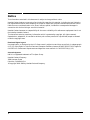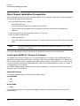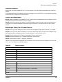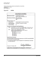
1
HP e3000 Fibre Channel Mass Storage Adapters
Service and User Manual
Edition 2
Manufacturing Part Number : 32650-90910
E0802
U.S.A. August 2002
Notice
The information contained in this document is subject to change without notice.
Hewlett-Packard makes no warranty of any kind with regard to this material, including, but not limited to,
the implied warranties of merchantability or fitness for a particular purpose. Hewlett-Packard shall not be
liable for errors contained herein or for direct, indirect, special, incidental or consequential damages in
connection with the furnishing or use of this material.
Hewlett-Packard assumes no responsibility for the use or reliability of its software on equipment that is not
furnished by Hewlett-Packard.
This document contains proprietary information which is protected by copyright. All rights reserved.
Reproduction, adaptation, or translation without prior written permission is prohibited, except as allowed
under the copyright laws.
Restricted Rights Legend
Use, duplication, or disclosure by the U.S. Government is subject to restrictions as set forth in subparagraph
(c) (1) (ii) of the Rights in Technical Data and Computer Software clause at DFARS 252.227-7013. Rights for
non-DOD U.S. Government Departments and Agencies are as set forth in FAR 52.227-19 (c) (1,2).
Acknowledgments
UNIX is a registered trademark of The Open Group.
Hewlett-Packard Company
3000 Hanover Street
Palo Alto, CA 94304 U.S.A.
© Copyright 2000–2002 by Hewlett-Packard Company.
2
Contents
1. Introduction
About HP Fibre Channel Mass Storage . . . . . . . . . . . . . . . . . . . . . . . . . . . . . . . . . . . . . . . . . . . . . . . . . . 10
For More Information . . . . . . . . . . . . . . . . . . . . . . . . . . . . . . . . . . . . . . . . . . . . . . . . . . . . . . . . . . . . . . . 10
Fibre Channel Adapter Supported. . . . . . . . . . . . . . . . . . . . . . . . . . . . . . . . . . . . . . . . . . . . . . . . . . . . . 10
2. Installation
Fibre Channel Installation Prerequisites . . . . . . . . . . . . . . . . . . . . . . . . . . . . . . . . . . . . . . . . . . . . . . . . . 14
Installing the A6795A PCI Tachyon XL2 Adapter . . . . . . . . . . . . . . . . . . . . . . . . . . . . . . . . . . . . . . . . 14
Attaching to Other Fibre Channel Devices . . . . . . . . . . . . . . . . . . . . . . . . . . . . . . . . . . . . . . . . . . . . . . 15
3. Verifying Installation
Configuring Fibre Channel Mass Storage Adapter . . . . . . . . . . . . . . . . . . . . . . . . . . . . . . . . . . . . . . . . . 18
Understanding Fibre Channel Device Paths. . . . . . . . . . . . . . . . . . . . . . . . . . . . . . . . . . . . . . . . . . . . . 18
Determining Fibre Channel Devices Connected to FC Adapter . . . . . . . . . . . . . . . . . . . . . . . . . . . . . 19
4. Troubleshooting
Introduction . . . . . . . . . . . . . . . . . . . . . . . . . . . . . . . . . . . . . . . . . . . . . . . . . . . . . . . . . . . . . . . . . . . . . . . .
Adapter LEDs . . . . . . . . . . . . . . . . . . . . . . . . . . . . . . . . . . . . . . . . . . . . . . . . . . . . . . . . . . . . . . . . . . . . .
TDUTIL . . . . . . . . . . . . . . . . . . . . . . . . . . . . . . . . . . . . . . . . . . . . . . . . . . . . . . . . . . . . . . . . . . . . . . . . . .
Reading VPD Information . . . . . . . . . . . . . . . . . . . . . . . . . . . . . . . . . . . . . . . . . . . . . . . . . . . . . . . . . . .
Auto Speed Negotiation . . . . . . . . . . . . . . . . . . . . . . . . . . . . . . . . . . . . . . . . . . . . . . . . . . . . . . . . . . . . .
HP Support Tools Manager (STM) under MPE/iX . . . . . . . . . . . . . . . . . . . . . . . . . . . . . . . . . . . . . . . . . .
Diagnostic Flowcharts . . . . . . . . . . . . . . . . . . . . . . . . . . . . . . . . . . . . . . . . . . . . . . . . . . . . . . . . . . . . . . . .
Flowchart 1 Procedures . . . . . . . . . . . . . . . . . . . . . . . . . . . . . . . . . . . . . . . . . . . . . . . . . . . . . . . . . . . . .
Flowchart 2 Procedures . . . . . . . . . . . . . . . . . . . . . . . . . . . . . . . . . . . . . . . . . . . . . . . . . . . . . . . . . . . . .
Flowchart 3 Procedures . . . . . . . . . . . . . . . . . . . . . . . . . . . . . . . . . . . . . . . . . . . . . . . . . . . . . . . . . . . . .
22
22
22
23
24
25
34
34
35
38
A. Technical Specifications
B. Regulatory Statements
FCC Statement (For USA Only) . . . . . . . . . . . . . . . . . . . . . . . . . . . . . . . . . . . . . . . . . . . . . . . . . . . . . . . .
IEC Statement (Worldwide) . . . . . . . . . . . . . . . . . . . . . . . . . . . . . . . . . . . . . . . . . . . . . . . . . . . . . . . . . .
DOC Statement (Canada) . . . . . . . . . . . . . . . . . . . . . . . . . . . . . . . . . . . . . . . . . . . . . . . . . . . . . . . . . . .
Spécification ATI Classe A (France) . . . . . . . . . . . . . . . . . . . . . . . . . . . . . . . . . . . . . . . . . . . . . . . . . . .
Laser Safety Statements . . . . . . . . . . . . . . . . . . . . . . . . . . . . . . . . . . . . . . . . . . . . . . . . . . . . . . . . . . . . . .
Certification and Classification Information. . . . . . . . . . . . . . . . . . . . . . . . . . . . . . . . . . . . . . . . . . . . .
Product Information. . . . . . . . . . . . . . . . . . . . . . . . . . . . . . . . . . . . . . . . . . . . . . . . . . . . . . . . . . . . . . . . . .
Usage Restrictions . . . . . . . . . . . . . . . . . . . . . . . . . . . . . . . . . . . . . . . . . . . . . . . . . . . . . . . . . . . . . . . . .
Laser Safety (Finland) LASERTURVALLISUUS . . . . . . . . . . . . . . . . . . . . . . . . . . . . . . . . . . . . . . . . .
42
42
42
42
44
44
45
45
45
Index . . . . . . . . . . . . . . . . . . . . . . . . . . . . . . . . . . . . . . . . . . . . . . . . . . . . . . . . . . . . . . . . . . . . . . . 47
3
Contents
4
Tables
Table 2-1. Cable Products . . . . . . . . . . . . . . . . . . . . . . . . . . . . . . . . . . . . . . . . . . . . . . . . . . . . . . . . . . 15
Table 4-1. A6795A LED Indicators . . . . . . . . . . . . . . . . . . . . . . . . . . . . . . . . . . . . . . . . . . . . . . . . . . . 22
Table A-1. A6795A . . . . . . . . . . . . . . . . . . . . . . . . . . . . . . . . . . . . . . . . . . . . . . . . . . . . . . . . . . . . . . . . 39
5
Tables
6
Figures
Figure 4-1. Flowchart 1: Boot Test . . . . . . . . . . . . . . . . . . . . . . . . . . . . . . . . . . . . . . . . . . . . . . . . . . .
Figure 4-2. Flowchart 2: Configuration Test . . . . . . . . . . . . . . . . . . . . . . . . . . . . . . . . . . . . . . . . . . .
Figure 4-3. Flowchart 3: Fibre Channel Connections Test . . . . . . . . . . . . . . . . . . . . . . . . . . . . . . . .
Figure B-1. VCCI Statement . . . . . . . . . . . . . . . . . . . . . . . . . . . . . . . . . . . . . . . . . . . . . . . . . . . . . . . .
Figure B-2. Class 1 Laser Label . . . . . . . . . . . . . . . . . . . . . . . . . . . . . . . . . . . . . . . . . . . . . . . . . . . . .
Figure B-3. A6795A . . . . . . . . . . . . . . . . . . . . . . . . . . . . . . . . . . . . . . . . . . . . . . . . . . . . . . . . . . . . . . .
34
35
37
43
44
46
7
Figures
8
Introduction
1 Introduction
This manual contains information on the Fibre Channel Mass Storage Host Bus Adapter supported on HP
e3000 Systems. Each supported adapter is identified along with general installation and troubleshooting
instructions. The adapters in this manual are for Fibre Channel Mass Storage only.
Chapter 1
9
Introduction
About HP Fibre Channel Mass Storage
About HP Fibre Channel Mass Storage
HP Fibre Channel Mass Storage is a high-speed connection for mass storage, capable of transmitting data
faster than existing SCSI mass storage interconnects.
HP Fibre Channel Mass Storage networks are ideal for data-intensive applications, including data mining,
atmospheric modeling, multimedia, geographic information systems, and medical imaging. HP Fibre Channel
host bus adapters (HBAs) are available for the following HP e3000 systems:
•
A-class systems
•
N-class systems
For the latest information on supported topologies, platforms, switches and devices, log on to the ITRC web
site (http://itrc.hp.com), and click on navigate knowledge trees and response center FAQs. In the
Hardware area, navigate the links to networks/mass storage connectivity/fibre channel/technical
support. Installation steps differ for various systems. Be sure to follow the information in this manual for
your adapter and your system. Refer to the system’s documentation for detailed installation procedures and
illustrations.
For More Information
American National Standards Institute (ANSI) committee chartered a Fibre Channel working group with
developing and documenting a Fibre Channel standard. For ANSI documentation information, contact:
Global Engineering Documents
15 Inverness Way East
Englewood, CO 80112-5704
Phone: 1-800-854-7179 or 1-303-792-2181
FAX: 1-303-397-2740
In addition, the Fibre Channel Industry Association has created a brief tutorial, Fibre Channel: Connection to
the Future, with overview information about Fibre Channel layers, fabrics, and services. This tutorial is
available at:
Fibre Channel Industry Association
404 Balboa Street
San Francisco, CA 94118
Phone: 1-800-272-4618 or 1-415-750-8355
Fax: 1-800-524-8317 or 1-415-751-4829
E-mail: [email protected]
URL: http://www.fibrechannel.com
Fibre Channel Adapter Supported
The Fibre Channel Device Adapter Card supported on N- and A-Class HP e3000 systems is:
•
10
A6795A — PCI 4X 2Gbps Single Port Fibre Channel Adapter
Chapter 1
Introduction
About HP Fibre Channel Mass Storage
This fibre channel adapter card utilizes the Tachyon XL2 chip, the newest member of the Tachyon family
product suite of Fibre Channel interface controllers. It operates at 2 Gigabits per second speed in a 4x PCI
slot. It can be plugged into any of the system PCI Bus slots and will present one fibre channel port to the
outside world.
The A6795A card can automatically sense the fibre channel link speed to operate at 1Gbps or 2Gbps, thus
enabling it to work with fibre channel devices supporting either speeds.
Chapter 1
11
Introduction
About HP Fibre Channel Mass Storage
12
Chapter 1
Installation
2 Installation
This chapter describes the installation procedures for the HP Fibre Channel Mass Storage host bus adapter
on HP e3000 systems.
Chapter 2
13
Installation
Fibre Channel Installation Prerequisites
Fibre Channel Installation Prerequisites
Before installing the HP Fibre Channel host bus adapter into any system, check that the following hardware
and software prerequisites have been met:
1. Verify the following product contents:
•
Grounding wrist strap
•
Fibre Channel driver software (included with MPE/iX OS)
•
Fibre Channel host bus adapter with an optical port protector attached (not included with all
adapters).
2. Verify that the MPE/iX operating system version is 7.5 or later.
3. Verify the cabling requirements:
•
Cable map (optional)
•
Fiber optic cable terminated with a duplex LC connector. Cable must be 50 or 62.5 micron multimode
cable.
NOTE
The A6795A adapter uses a fibre optic duplex M/M cable terminated with a SFF (small
form factor) LC connector.
For a list of cable product numbers, see the section “Attaching to Other Fibre Channel Devices”.
Installing the A6795A PCI Tachyon XL2 Adapter
The A6795A Fibre Channel Tachyon XL2 PCI host bus adapter is a single port 2 Gb-capable adapter that
operates at bus speeds up to 66 MHz with a 64-bit bus width. With auto-speed negotiation, it is capable of a 1
Gb / 2 Gb data transfer rate. The supported HP e3000 systems must be running MPE/iX 7.5 or later version.
For more information about Auto Speed Negotiation, see the “Auto Speed Negotiation” section in Chapter 4,
“Troubleshooting,” of this manual.
The A6795A adapter supports arbitrated loop and fabric topologies. It can connect to Fibre Channel devices
with either 2Gb or 1Gb interface.
Supported Platforms
The A6795A adapter supports the following HP e3000 systems:
A-class Models
•
A400
•
A500
N-class Model
•
N4000
For the latest information on all supported topologies, platforms, switches and devices, contact your HP
Representative.
14
Chapter 2
Installation
Fibre Channel Installation Prerequisites
Installation Guidelines
Be sure that you have installed MPE/iX 7.5 or later version on your HP e3000 system before you install the
adapter.
If you intend to boot with this adapter, verify that the system is running MPE/iX 7.5 or later operating system
and that the PDC firmware is the correct version.
Installing the A6795A Adapter
Step 1: Install the adapter in an available PCI slot. To shut down the system and install the adapter, refer to
the appropriate service documentation for your system.
Step 2: Attach fibre cabling to the adapter. The A6795A adapter uses a fibre optic cable terminated with an
LC connector. To attach the adapter to other devices, go to the section, “Attaching to Other Fibre Channel
Devices”.
Attaching to Other Fibre Channel Devices
Step 1: Be sure you have removed the Fibre Channel host bus adapter’s optical port protector (if included).
Step 2: Be sure you have attached a duplex LC connector cable to the Fibre Channel host bus adapter. Align
the slotted plug with the keyed connector. Push the connector in until you hear it click.
Step 3: Attach the free end of the cable to a compatible Fibre Channel device.
Step 4: Reconnect the power cord, if necessary, and power up the system.
Step 5: Continue with Chapter 3, “Verifying Installation.”
Table 2-1 lists Fibre Channel cables that can be used with Fibre Channel Host Bus Adapters. Be sure to use
LC-LC or LC-SC cables for the A6795A adapter.
Table 2-1
Cable Products
SC-SC
A3583A
Fibre Channel Cable 2m 50uM/125uM multimode
A3531A
Fibre Channel Cable 16m 50uM/125uM multimode
A3735A
Fibre Channel Cable 50m 50uM/125uM multimode
A3736A
Fibre Channel Cable 100m 50uM/125uM multimode
LC-LC
C7524A
Fibre Channel Cable 2m LC duplex M/M
C7525A
Fibre Channel Cable 16m LC duplex M/M
C7526A
Fibre Channel Cable 50m LC duplex M/M
C7527A
Fibre Channel Cable 200m LC duplex M/M
LC-SC
Chapter 2
15
Installation
Fibre Channel Installation Prerequisites
Table 2-1
Cable Products (Continued)
C7529A
Fibre Channel Cable 2m LC-SC 50/125 duplex M/M Optical
C7530A
Fibre Channel Cable 16m LC-SC 50/125 duplex M/M Optical
Adapter/Extenders
C7534A
Fibre Channel Adapter SC F/F
Adapter Kit
C7540A
16
Fibre Channel Adapter Kit: Includes 2m LC/SC Cable and F/F extenders
Chapter 2
Verifying Installation
3 Verifying Installation
This chapter describes the procedures for configuring and verifying the installation of HP Fibre Channel
Mass Storage host bus adapter on HP e3000 systems.
Chapter 3
17
Verifying Installation
Configuring Fibre Channel Mass Storage Adapter
Configuring Fibre Channel Mass Storage Adapter
As with other device adapter cards for HP e3000, fibre channel adapters can also be configured through the
MPE/iX utility SYSGEN. Assume a Fibre Channel adapter card at path 0/8/0/0. Start by configuring the first
path component System Bus Location equal to zero “0”. Then configure the Local Bus Number equal to eight
“8”, PCI Device equal to zero “0”, and PCI Function equal to zero “0”. In most cases, the System Bus
component and Local Bus number component may already be configured. If so, directly proceed to configure
the PCI Device component.
io> ap 0 id=pat_ioa_bc
io> ap 0/8 id=pat_pci_bc
io> ap 0/8/0 id=pci_device
io> ap 0/8/0/0 id=A6795A
To check that the FC Device Adapter Card is properly configured:
io> lp 0/8/0/0
PATH: 0/8/0/0
ID: A6795A
PMGR: FC_DAM
LMGR:
LDEV:
TYPE: DA
PMGRPRI: 6
MAXIOS: 0
Note that the PMGR should be set to “FC_DAM,” which is the manager software for FC device adapter card.
After configuring the adapter card through SYSGEN, reboot the system. (If the FC card is configured online
using online configuration tool IOCONFIG instead of SYSGEN, the reboot is not required).
When the system is rebooted with FC adapter configured, the software driver for the FC adapter initializes
the card and identifies FC devices connected to the card. At this time, a message appears on the system
console saying:
td: claimed Tachyon XL2 Fibre Channel Mass Storage card at 0/8/0/0
Scanning for fibre channel devices at 0/8/0/0. This may take a while...
The appearance of this message indicates that the card has been initialized successfully and the software
identified any FC devices connected to this adapter card. The list of FC devices/LUNs thus identified is not
printed immediately. This list can later be generated by running another MPE/iX utility called FCSCAN,
which can be run from the MPE/iX CI prompt.
Understanding Fibre Channel Device Paths
Before identifying and configuring fibre channel devices connected to the adapter, understand about Fibre
Channel device hardware path format, used in MPE/iX. Unlike a SCSI device path, a Fibre Channel device
path is interpreted differently. The path used in MPE/iX to represent a fibre channel device is given below:
System Bus Location / Local Bus Number / PCI Device / PCI Device Function. FC NPort.FC LUN
Note that the second to last component here is “FC NPort” whereas in the case of SCSI devices it would have
been a “SCSI Target”. FC Nport a “fibre channel node port” which represents the connection point for a fibre
channel device. Under the FC Nport, there can be multiple LUNs of the FC device which are accessible in the
same way as SCSI LUNs. A single FC device can support multiple Nports and each Nport can have varying
number of LUNs under it. This is analogous to multiple SCSI LUNs under a SCSI Target.
18
Chapter 3
Verifying Installation
Configuring Fibre Channel Mass Storage Adapter
The last component in the FC path represents an “FC LUN” while in a SCSI device path it would be a “SCSI
LUN”. Although the FC LUN is functionally the same as a SCSI LUN, it is termed differently to signify that
it can take on much larger values.
Determining Fibre Channel Devices Connected to FC Adapter
There is no way in the HP e3000 system firmware Main Menu to identify the FC devices connected to an FC
adapter card. Running ODE MAPPER2 from ISL does help to identify some FC devices but even this may not
list out all the LUNs under the FC devices. For configuring in MPE/iX we ultimately need the FC LUN paths.
In order to assist the System Administrator in identifying the FC devices and LUNs accessible from an FC
adapter card, MPE/iX provides a new utility called FCSCAN. This utility is present in the system as
“FCSCAN.PUB.SYS”.
Before using FCSCAN to identify FC devices/LUNs under an FC adapter, you need to make sure that the FC
adapter has been configured in the system. The steps mentioned under the section“Configuring Fibre
Channel Mass Storage Adapter” should have been completed before running FCSCAN utility.
A sample output generated on running the FCSCAN utility is shown below:
:fcscan
FCSCAN has found the following Fibre Channel I/O Adapter Cards and Devices on this system.
SYSGEN PATH
DESCRIPTION
BOOT MENU PATH
=============
=============
================
0/8/0/0
Fibre Channel Adapter
0/8/0/0.0
Fibre Channel N-Port
0/8/0/0.0.0
HP OPEN-3 disk
0/8/0/0.8.0.0.0.0.0
0/8/0/0.0.1
HP OPEN-3 disk
0/8/0/0.8.0.0.0.0.1
0/8/0/0.0.105
HP OPEN-3 disk
0/8/0/0.8.0.0.0.13.1
0/8/0/0.95
Fibre Channel N-Port
0/8/0/0.95.0
HP A6188A disk
0/8/0/0.8.0.95.0.0.0
0/8/0/0.95.5
HP A6188A disk
0/8/0/0.8.0.95.0.0.5
0/8/0/0.95.10
HP A6188A disk
0/8/0/0.8.0.95.0.1.2
0/8/0/0.95.50
HP A6188A disk
0/8/0/0.8.0.95.0.6.2
The output from FCSCAN shows the list of FC adapter cards and devices present in the system. The
hardware paths printed by FCSCAN can be directly used in SYSGEN to configure the corresponding device.
The output from the FCSCAN utility shows the following information:
•
SYSGEN PATH:
— Hardware path of the FC adapter card or device. This is the path which is to be used in SYSGEN to
configure the card or device in the system.
•
DESCRIPTION:
— Description about whether the path specifies an FC card or device. If device, it also specifies the model
and type of the device.
•
BOOT MENU PATH:
Chapter 3
19
Verifying Installation
Configuring Fibre Channel Mass Storage Adapter
— Path value for an FC device to be used in the system Boot Command Handler or firmware Main Menu
to set that particular device as the primary path. The boot menu path is a detailed long format path
unlike the simplified SYSGEN path. It is necessary to use this long path in boot menu because the
system firmware can understand only this format to access devices. To install on, or boot from an FC
disk, the primary path will be set to this long path for that disk as printed by FCSCAN.
The above sample output shows that there is a Fibre Channel Adapter card configured in the system at path
0/8/0/0. Under this card, there are some devices listed.
Path 0/8/0/0.0 shows an FC N_Port (Node Port) which indicates the fibre channel port of a device connected to
the card. FC N_port is required to be configured in SYSGEN while configuring devices. The output also shows
three disks of type HP OPEN-3 shown with paths 0/8/0/0.0.0, 0/8/0/0.0.1 and 0/8/0/0.0.105. The last
components of these paths refer to the LUN number of these disks. The type HP OPEN-3 usually refers to an
XP512 device disk. Since the hardware paths of these three disks come under Nport 0/8/0/0.0, they all fall
under the same Nport in the XP512 device.
Path 0/8/0/0.95 shows another FC N_Port (Node Port) indicating another device is connected to the card.
Under this N_Port, there are four disk LUNs of type HP A6188A shown with paths 0/8/0/0.95.0, 0/8/0/0.95.5,
0/8/0/0.95.10 and 0/8/0/0.95.50. The type HP A6188A refers to the Virtual Array device A6188A.
FCSCAN utility provides a list of all device N_Ports and LUNs connected to the adapter card. This
information should be used to configure them in SYSGEN. Further details on FCSCAN utility and the steps
for configuring FC device LUNs are covered in the MPE/iX Release 7.5 Communicator document.
NOTE
20
If FCSCAN output shows only the adapter card but no devices under it, then most likely the
device has not been connected properly. Verify the FC cable connecting the FC device to the
adapter. Try again by running FCSCAN with “-h” option. For more details how to run FCSCAN
with this option, refer to the MPE/iX 7.5 Communicator document.
Chapter 3
Troubleshooting
4 Troubleshooting
This chapter describes the troubleshooting tools available to help diagnose any problems you may experience
with the adapters. It covers fibre channel adapter LEDs, online and offline diagnostic tools, and explains the
diagnostic flowcharts in the latter part of this chapter.
Chapter 4
21
Troubleshooting
Introduction
Introduction
Troubleshooting Fibre Channel problems can be difficult because a variety of hardware and software
components may be involved. Also, the problem affecting the system may originate in another part of the
Fibre Channel mass storage interconnect. A systematic approach to troubleshooting is helpful.
If you cannot solve the problem on your own, contact your Hewlett-Packard representative.
NOTE
Before using these troubleshooting steps, you must have installed, configured, and verified the
Fibre Channel hardware on the host and on any devices.
Adapter LEDs
The status LEDs on the fibre channel mass storage adapter indicates the state of the adapter. The following
Table 4-1 describes the different states for the A6795A adapter.
Table 4-1
PWR/ACT
(green)
A6795A LED Indicators
LNK/SPD
(green/amber)
Probable Cause
Recommended
Action
Off
Off
Machine not powered On
Power on machine
On
Off
During power up During link
Initialization
No action required
On
Green
Fibre Channel link is at 2Gb speed
No action required
On
Amber
Fibre Channel link is at 1Gb speed
No action required
Flashing
On
After initialization, flashes only
when there is I/O activity.
No action required
If the LNK/SPD LED remains off, check cable connections, or call your HP representative.
TDUTIL
TDUTIL is an MPE/iX utility, available for troubleshooting fibre channel host bus adapters, supported on HP
e3000 systems. This utility provides the ability to display information such as the N_Port ID, Node
World-Wide Name, Port World-Wide Name, link speed, chip revision number, VPD (Vital Product Data)
information and more.
The utility can be run from the MPE/iX CI command prompt by giving the FC adapter hardware path as
parameter.
:tdutil <adapter hardware path>
TDUTIL supports usage of the options while invoking the utility, but these options are meant to be used only
by HP Support Representatives for troubleshooting. Customers are advised to use TDUTIL only by
specifiying the adapter path and not make use of any of the options. For detailed information on this utility,
refer to the article on TDUTIL in the MPE/iX 7.5 Communicator document.
A sample output of TDUTIL utility is shown below for the A6795A adapter:
22
Chapter 4
Troubleshooting
Introduction
:tdutil 0/8/0/0
Vendor ID is = 0x00103c
Device ID is = 0x001029
XL2 Chip Revision No is = 2.2
PCI Sub-system Vendor ID is = 0x00103c
PCI Sub-system ID is = 0x00128c
Topology = PTTOPT_FABRIC
Link Speed = 1Gb
Local N_Port_id is = 0x011c00
N_Port Node World Wide Name = 0x50060b00001000d4
N_Port Port World Wide Name = 0x50060b00001000d3
Driver state = ONLINE
Hardware Path is = 0/8/0/0
Number of Assisted IOs = 126053
Number of Active Login Sessions = 1
Maximum Frame Size = 960
Driver Version = @(#) HP Fibre Channel Tachyon TL/TS/XL2 Driver B.11.00.10 (AR1201) Jan
9 2002
To know whether the fibre channel link on the adapter card is active, check to see that the Driver state
printed in the above output is ONLINE.
CAUTION
TDUTIL is a powerful diagnostic tool that may cause problems if used incorrectly.
Reading VPD Information
You can use TDUTIL with the A6795A adapter to read VPD (Vital Product Data) information on the adapter,
which can be useful in troubleshooting problems remotely. The command for retrieving VPD information is:
:tdutil <adapter hardware path> vpd
Following is an example of the information that displays:
V I T A L P R O D U C T D A T A
--------- ------------- ------Product Description :’A6795A 2Gbps/1Gbps Fibre Channel 4X PCI HBA’
Part number :’A6795-62001’
Engineering Date Code :’A-4142’
Part Serial number :’A56466014504’
Misc. Information :’PW=15W’
Mfd. Date :’A-4142’
Check Sum : 0x46
EFI version :’000000’
Asset Tag :’NA’
Chapter 4
23
Troubleshooting
Introduction
Auto Speed Negotiation
The A6795A adapter is capable of transferring data at 1 Gb or 2 Gb per second. The adapter will
automatically negotiate to find the highest speed that is common to the port and to the infrastructure
connecting the port.
To display the link speed along with other existing adapter information, use the command:
: tdutil <adapter hardware path>
The current link speed is displayed as part of the output. Once the adapter is operating at a certain speed, it
will not attempt to negotiate again unless a link fails, or it detects a chip reset.
24
Chapter 4
Troubleshooting
HP Support Tools Manager (STM) under MPE/iX
HP Support Tools Manager (STM) under MPE/iX
This section describes how to use STM to gather information about the Fibre Channel adapters and diagnose
problems. If you are not familiar with STM, check out the new STM MPE/iX Quick Reference Guide at the
following URL: http://docs.hp.com/hpux/diag. Then select MPE/iX Diagnostics.
Use the CSTM command to start STM in Command Line Mode.
NOTE
PUB:CSTM
CSTM B8343AA.75.00
Version created MON, JAN 28, 2002 12:02 PM
Running Command File (/usr/sbin/stm/ui/config/.stmrc).
This operation may take approximately one minute.
-- Information -MPE/iX Support Tools Manager --Product Number B8343AA, Version A.75.00
(C) Copyright Hewlett Packard Co. 1995-2002 All Rights Reserved
Use of this program is subject to the licensing restrictions described in "Help-->On Version".
not be liable for any damages resulting from misuse or unauthorized use of this program.
•
HP shall
Information tool provides information about a Fibre Channel adapter without resetting the adapter.
The following is an example information log for a e3000/A500-200-14 system: (user input in BOLD)
cstm>MAP
Dev
Num
Path
Product
===
================= ======================
1
system
system ()
2
0
PCI Bus Adapter (582)
3
0/0
PCI Bus Adapter (782)
4
0/0/1/0
PCI SCSI Interface (10000
5
0/0/1/0.16.0
Unknown ()
6
0/0/1/0.17.0
Unknown ()
7
0/0/1/1
PCI SCSI Interface (10000
8
0/0/1/1.15.0
SCSI Disk (SEAGATEST39204
9
0/0/2/0
PCI SCSI Interface (10000
10
0/0/2/0.6.0
Unknown ()
11
0/0/2/1
PCI SCSI Interface (10000
12
0/0/2/1.6.0
Unknown ()
13
0/0/2/1.15.0
SCSI Disk (SEAGATEST39204
Chapter 4
Last
Last Op
Active Tool
Status
===========
=======
25
Troubleshooting
HP Support Tools Manager (STM) under MPE/iX
14
0/2
PCI Bus Adapter (782)
15
0/2/0/0
PCI 100 BaseT LAN Interfa
16
0/4
PCI Bus Adapter (782)
17
0/4/0/0
PCI SCSI Interface (10000
18
0/6
PCI Bus Adapter (782)
19 0/6/0/0
FC Interface (HP6795A_Tac Information
20 0/6/2/0
FC Interface (HP5158A_Tac Diagnose
21
8
MEMORY (9b)
22
160
CPU (5cb)
23
162
CPU (5cb)
cstm> SEL DEV 19
cstm>INFO
-- Updating Map -Updating Map...
cstm>IL
-- Converting a (1368) byte raw log file to text. -Preparing the Information Tool Log for FC Interface on path 0/6/0/0 File ...
-- Information Tool Log for FC Interface on path 0/6/0/0 --
Log creation time: Mon Jan 21 05:16:46 2002
Hardware path: 0/6/0/0
Product ID:
FC Interface
Hardware Path:
0/6/0/0
Module Type:
Bus Adapter
Vendor ID:
0x103c
PCI Device ID:
0x1029
PCI Subsystem Vendor ID:
0x103c
PCI Subsystem ID:
0x128c
Topology:
Direct Fabric Attach (N_Port to F_Port)
Channel N_PORT_ID:
0x11c00
N_Port Port World Wide Name: 50060B00001000D3
N_Port Node World Wide Name: 50060B00001000D4
Tachyon TL/TS Major Revision:2
Tachyon TL/TS Minor Revision:2
Memory Address Base:
0
ROM Alternate Addr Base:
0
Lower I/O Address Base:
0
26
Chapter 4
Troubleshooting
HP Support Tools Manager (STM) under MPE/iX
Upper I/O Address Base:
0
Information Tool Log for FC Interface on path 0/6/0/0 --
•
Logtool utility extracts log errors and allows them to be viewed. This tool provides information about a
Fibre Channel adapter without resetting the adapter.
cstm>RU LOGTOOL
-- Logtool Utility -To View a Summary of Events in a Raw Log
1. Select a raw (unformatted) log file.
(File Menu -> "Select Raw")
The current log file ends in ".cur", e.g. "log1.raw.cur".
You do not have to switch logs.
2. View the summary of the selected log file. (View Menu -> "Raw Summary")
To Format a Raw Log
1. Set the format filter for the types of entries you want to see.
(Filters Menu -> "Format").
To see all entries, skip this step.
2. Format the raw log file. (File Menu -> "Format Raw")
3. Display the formatted file. (View Menu -> "Formatted Log")
4. To further narrow the entries displayed, set a display filter.
(Filters Menu -> "Display" -> "Formatted")
For more information, use the on-line help (Help Menu -> "General help").
Logtool Utility>SR
-- Logtool Utility:
Select Raw Log File --
Select a raw log file or files to view, format or filter.
[/var/stm/logs/os/log542.raw.cur]
Path: /var/stm/logs/os/
File Name:
(RETURN IF YOU WANT CURRENT FILE OR ENTER FILE NAME)
Select Raw processing file /var/stm/logs/os/log542.raw.cur
Number of entries analyzed is 1.
Number of entries analyzed is 51.
Number of entries analyzed is 60.
The Select Raw operation completed.
Chapter 4
27
Troubleshooting
HP Support Tools Manager (STM) under MPE/iX
The Display Raw Summary operation is currently in progress.
-- Converting a (1804) byte raw log file to text. -Preparing the Logtool Utility: View Raw Summary File ...
.... ######.cup.hp.com
:
##.##.##.### ....
-- Logtool Utility: View Raw Summary --
Summary of: /var/stm/logs/os/log542.raw.cur
Date/time of first entry:
Mon Jan 21 08:37:28 2002
Date/time of last
Wed Jan 30 11:44:34 2002
entry:
Number of LPMC entries:
0
Number of System Overtemp entries:
0
Number of LVM entries:
0
Number of Logger Event entries:
0
Number of I/O Error entries:
60
Device paths for which entries exist:
(7)
0/6/0/0.72508.5
(7)
0/6/0/0.72508.15
(4)
0/6/0/0
(4)
0/6/0/0.72508
(38)
0/0/2/0.6.0
Products for which entries exist:
(4)
FC Interface
(4)
VA 7100
(52)
Product Qualifiers for which entries exist:
(4)
HP6795A_Tachyon_XL2
(4)
HPA6188A
(52)
28
Chapter 4
Troubleshooting
HP Support Tools Manager (STM) under MPE/iX
Logger Events for which entries exist:
(14)
SCSI_DISK_AND_ARRAY_DM
(4)
FC_DAM
(4)
FCP_NM
(38)
SCSI_TAPE_DM
-- Logtool Utility: View Raw Summary -View
- To View the file.
Print
- To Print the file.
SaveAs - To Save the file.
Enter Done, Help, Print, SaveAs, or View: [Done] (return)
Logtool Utility>FF
-- Logtool Utility: Set Format Filter -Date and time of first log entry:
Mon Jan 21 08:37:28 2002
Date and time of last log entry:
Mon Feb
4 10:26:00 2002
Format entries logged within the following dates/times:
Starting Date and Time:: (mm/dd/yyyy|hh:mm:ss)[01/21/2002|08:37:28] (return)
Ending Date and Time:: (mm/dd/yyyy|hh:mm:ss)[02/04/2002|10:26:00] (return)
Lowest Entry id : 0x3c4c199800000001 (return)
Highest Entry id: 0x3c5ea80800000001 (return)
Display entries with entry ids within the following range:
Starting entry id (hex) : [0x3c4c199800000001] (return)
Ending entry id (hex)
: [0x3c5ea80800000001] (return)
Total Entries: 61
Display entries within the following range:
Starting Entry Number: [1] (return)
Ending Entry Number : [61] (return)
Display entries of the following types:
Low Priority Machine Check? (y/n)[yes] N
System Overtemp? (y/n)[yes] N
LVM? (y/n)[yes] N
Log Suspend and Resume? (y/n)[yes] N
I/O Error Entries:
*
1 All I/O Errors (io_all)
2 No I/O Errors (io_none)
3 Filter I/O Errors (qualifier choices below) (io_filt)
Enter selection: [io_all] io_filt
Device Path:
Chapter 4
29
Troubleshooting
HP Support Tools Manager (STM) under MPE/iX
1 0/6/0/0.72508.5
2 0/6/0/0.72508.15
3 0/6/0/0
4 0/6/0/0.72508
5 0/0/2/0.6.0
Enter selection [done]: (return)
Products:
1 FC Interface
2 VA 7100
3
Enter selection [done]: 1
Products:
*
1 FC Interface
2 VA 7100
3
Enter selection [done]: (return)
Product Qualifiers:
1 HP6795A_Tachyon_XL2
2 HPA6188A
3
Enter selection [done]: 1
Product Qualifiers:
*
1 HP6795A_Tachyon_XL2
2 HPA6188A
3
Enter selection [done]: (return)
Loggers:
1 SCSI_DISK_AND_ARRAY_DM
2 FC_DAM
3 FCP_NM
4 SCSI_TAPE_DM
Enter selection [done]: 2
Logtool Utility>FR
-- Logtool Utility:
Format Raw Log File --
Select a directory into which to place the formatted file:
Directory: [/var/stm/logs/os/]
30
Chapter 4
Troubleshooting
HP Support Tools Manager (STM) under MPE/iX
The Format Raw operation is currently in progress.
Entries processed is 1 of 61 total entries; entries formatted is 0.
Entries processed is 51 of 61 total entries; entries formatted is 2.
Entries processed is 61 of 61 total entries; entries formatted is 4.
The Format Raw operation completed successfully. The following raw log file(s)
were formatted into /var/stm/logs/os/log542.fmt9:
/var/stm/logs/os/log542.raw.cur
The Display Formatted Summary operation is currently in progress.
-- Converting a (1124) byte raw log file to text. -Preparing the Logtool Utility: View Formatted Summary File ...
....####.cup.hp.com
:
##.##.##.###....
Logtool Utility: View Formatted Summary –
Summary of:
/var/stm/logs/os/log542.fmt9
Formatted from:
/var/stm/logs/os/log542.raw.cur
Date/time of first entry:
Mon Jan 21 08:37:28 2002
Date/time of last
Mon Feb
entry:
4 10:26:00 2002
Number of LPMC entries:
0
Number of System Overtemp entries:
0
Number of LVM entries:
0
Number of Logger Event entries:
0
Number of I/O Error entries:
4
Device paths for which entries exist:
(4)
0/6/0/0
Products for which entries exist:
(4)
FC Interface
Product Qualifiers for which entries exist:
(4)
HP6795A_Tachyon_XL2
Logger Events for which entries exist:
Chapter 4
31
Troubleshooting
HP Support Tools Manager (STM) under MPE/iX
(4)
FC_DAM
Device Types for which entries exist:
(4)
Interface
Device Qualifiers for which entries exist:
(4)
FibreTL
-- Logtool Utility: View Formatted Summary -View
- To View the file.
Print
- To Print the file.
SaveAs - To Save the file.
Enter Done, Help, Print, SaveAs, or View: [Done] DD
isplay of the formatted log file summary was successful.
Logtool Utility>FLT
he Display Formatted Log operation is currently in progress.
-- Converting a (8168) byte raw log file to text. -Preparing the Logtool Utility: View Formatted Log File ...
....#####.cup.hp.com
:
##.##.##.###....
-- Logtool Utility: View Formatted Log --
Formatted Output of:
/var/stm/logs/os/log542.fmt9
Formatted from:
/var/stm/logs/os/log542.raw.cur
Date/time of first entry:
Mon Jan 21 08:37:28 2002
Date/time of last
Mon Feb
entry:
4 10:26:00 2002
Display Filters:
Starting Date: Mon Jan 21 08:37:28 2002
Ending Date:
Mon Feb
4 10:26:00 2002
=-+-=-+-=-+-=-+-=-+-=-+-=-+-=-+-=-+-=-+-=-+-=-+-=-+-=-+-=-+-=-+-=-+-=-+-=-+-=
Entry Type:
I/O Error
Entry logged on Fri Jan 25 15:43:12 2002
Entry id: 0x3c51c36000000005
Device Path:
32
0/6/0/0
Chapter 4
Troubleshooting
HP Support Tools Manager (STM) under MPE/iX
Product:
FC Interface
Product Qualifier:
HP6795A_Tachyon_XL2
Logger:
FC_DAM
Device Type:
Interface
Device Qualifier:
FibreTL
--------------------------------------------------------------------------I/O Log Event Information:
I/O Event Class - Software Triggered Event
I/O Transaction Number - 0x00000000
Length of Hardware Status Logged - 0 bytes
Length of Driver Information Logged - 144 bytes
Low Level I/O (LLIO) Status:
0x11ff03e7
Subsystem field = 999; Proc. Num. = -1; Error Num. = 17
Severity Level: Information
Fibre Channel Driver received an ERQ Frozen interrupt from
the adapter.
Raw manager data:
0x0000: 00 00 00 06
17 D3 7C 80
00 00 00 00
00 00 00 01
0x0010: 43 54 44 49
53 52 2E 43
43 57 53 49
4F 2E 54 4C
0x0020: 32 47 53 55
42 4D 00 7A
00 00 00 00
C0 21 00 08
0x0030: 00 00 00 0A
02 1D 92 F0
00 91 DB 18
83 FC EB 04
0x0040: 08 00 45 00
00 00 00 0B
FF FA 20 00
FF FA 20 00
0x0050: 00 00 00 08
00 00 00 0A
00 00 14 51
07 00 FF FF
0x0060: FF FF FF FF
00 10 83 FC
EB 04 08 00
D5 D2 3D 50
0x0070: D5 D2 1D 50
00 00 00 01
00 00 00 08
00 00 00 00
0x0080: D4 01 54 00
D4 01 54 00
00 00 00 00
00 00 10 00
=-+-=-+-=-+-=-+-=-+-=-+-=-+-=-+-=-+-=-+-=-+-=-+-=-+-=-+-=-+-=-+-=-+-=-+-=-+-
•
Diagnose tool runs a loopback test on a Fibre Channel adapter. This test is destructive and should only be
run by qualified personnel.
Chapter 4
33
Troubleshooting
Diagnostic Flowcharts
Diagnostic Flowcharts
The diagnostic flowcharts provide the following tests:
•
Flowchart 1: Boot Test. Verifies that the system boots correctly over Fibre Channel.
•
Flowchart 2: Configuration Test. Verifies the configuration of the mass storage interface on a host
using the FCSCAN utility.
•
Flowchart 3: Fibre Channel Connections Test. Checks that all the hardware connections between
the system and the Fibre Channel mass storage devices are connected and operational.
Figure 4-1
Flowchart 1: Boot Test
Flowchart 1 Procedures
A. Is the system bootable over the Fibre Channel? Only certain systems can boot over the Fibre
Channel adapter. If your system is not capable, you must boot from a SCSI device.
34
Chapter 4
Troubleshooting
Diagnostic Flowcharts
B. Is firmware version adequate? Check the firmware revision on your system for the minimum required
date code for your adapter. If Yes, go to step D; if No, go to C.
C. Update firmware. Update the firmware to the appropriate level.
D. Is the Fibre Channel adapter installed correctly? If yes, go to 4. If no, go to step E.
E. Is the Fibre Channel adapter properly seated? Shut down the HP e3000 system by entering: CTRL-A
/ shutdown. Power down the system and disconnect the cables. Check that the adapter is properly seated
in the backplane. To verify the installation, go back to step A.
Figure 4-2
Flowchart 2: Configuration Test
2
A
Run
FCSCAN
B
Is FC
Adapter
displayed?
G
No
C
Run
IOCONFIG
Yes
Devices
Displayed
No
4
Yes
Done
D
E
Configure
Adapter using
IOCONFIG
Is FC
Adapter
configured?
No
Yes
2
F
Call HP
Flowchart 2 Procedures
A. Run the FCSCAN utility to display information about FC adapter and devices present in the system.
Chapter 4
35
Troubleshooting
Diagnostic Flowcharts
B. FC adapter displayed? FCSCAN shows FC adapters configured in the system. If the adapter is not
displayed, go to C. If it is displayed, continue with G.
C. Run IOCONFIG to verify if the required FC adapter is configured in the system.
D. Is FC adapter configured? If not configured, go to E. If configured but FCSCAN still is not able to
display it, go to F (Call HP Support Representative).
E. Configure Adapter. Using IOCONFIG, configure the FC adapter in your system.
F. Call HP. Contact the HP Support Representative and communicate the problem.
G. Device Displayed? If devices are not displayed, go to number 4 on flowchart 3.
36
Chapter 4
Troubleshooting
Diagnostic Flowcharts
Figure 4-3
Chapter 4
Flowchart 3: Fibre Channel Connections Test
37
Troubleshooting
Diagnostic Flowcharts
Flowchart 3 Procedures
A. Verify: Fibre Channel adapter properly seated. Shut down the HP e3000 system by entering:
CTRL-A / shutdown. Power down the system and disconnect the cables. Check that the adapter is
properly seated in the backplane. To verify, power up the system.
B. Adapter problem: call HP. Contact the HP Support Representative and communicate the problem.
C. Verify: connectors solidly connected. Without powering down the system, make sure the connectors
on the fiber optic cable match the keyed connectors on the adapter and are solidly connected.
D. Verify: connection to Fibre Channel Mass Storage device. Make sure the Fibre Channel cable is
fully connected to the Fibre Channel Mass Storage device and the device is operating. Follow the
instructions in the device manual to check the device state. Try changing the connection to a different
port on the Fibre Channel Mass Storage device, if possible. After checking the connections, go back to
flowchart 1.
E. Verify: Fibre Channel Mass Storage device powered on. Make sure the Fibre Channel Mass
Storage device is powered on.
F. Verify: run Fibre Channel Mass Storage device-specific diagnostics. If diagnostics are available to
troubleshoot the Fibre Channel Mass Storage device, follow the steps to verify that the device is
functioning properly. After verification, go back to flowchart 1.
38
Chapter 4
Technical Specifications
A Technical Specifications
This appendix provides technical specifications for HP e3000 Fibre Channel Host Bus Adapters.
Table A-1
A6795A
Characteristics
2125 Mbps/1063 Mbps short-wave, SFF non-OFC
Supported SPUs
A-class, N-class HP e3000
Supported OS
MPE/iX 7.5
Connector
LC Duplex
Slot
PCI
Physical
Length
168 mm (6.60 inches)
Width
89 mm (3.50 inches)
Height
20 mm (.80 inches)
Weight
0.105Kg (0.23 lbs)
Electrical
5 watts (nominal); 15 watts (max)
Standards
Complies with ANSI standards (ANSI X3T11) for standard Fibre Channel
Environmental
Temperature
+5 to +40 degrees C (+41 to +104 F) operating, -40 to +70 degrees C (-40 to
+177 F) non operating
Relative
Humidity
5% to 90% @ 65 degrees C (149 degrees F) non-condensing, non-operating.
20% to 80% @ 40 degrees C (104 degrees F) non-condensing, operating.
Altitude
4.5 km (15,000 ft)
Electromagnetic
USA
FCC Class A
Europe
CISPR-22 Class A
Germany
FTZ-1046 (VDE Level B)
Japan
VCCI Class I
Laser Safety
Appendix A
Class 1
39
Technical Specifications
40
Appendix A
Regulatory Statements
B Regulatory Statements
This appendix contains the regulatory statements and declarations of conformity for the HP e3000 Fibre
Channel Host Bus Adapters.
Appendix B
41
Regulatory Statements
FCC Statement (For USA Only)
FCC Statement (For USA Only)
The Federal Communications Commission (in 47 CFR 15.105) has specified that the following notice be
brought to the attention of the users of this product.
This equipment has been tested and found to comply with the limits for a Class A digital device, pursuant to
Part 15 of the FCC Rules. These limits are designed to provide reasonable protection against harmful
interference when the equipment is operated in a commercial environment. This equipment generates, uses,
and can radiate radio frequency energy and, if not installed and used in accordance with the instruction
manual, may cause harmful interference to radio communications. Operation of this equipment in a
residential area is likely to cause harmful interference in which case the user will be required to correct the
interference at his own expense. The end user of this product should be aware that any changes or
modifications made to this equipment without the approval of Hewlett-Packard could result in the product
not meeting the Class A limits, in which case the FCC could void the user’s authority to operate the
equipment.
IEC Statement (Worldwide)
This is a Class A product. In a domestic environment this product may cause radio interference in which case
the user may be required to take adequate measures.
DOC Statement (Canada)
This Class A digital apparatus meets all requirements of the Canadian interference-Causing Equipment
Regulations.
Cet appareil numerique de la classe A respecte toutes les exigences du Réglement sur le materiel brouilleur
du Canada.
Spécification ATI Classe A (France)
DECLARATION D’INSTALLATION ET DE MISE EN EXPLOITATION
d’un matériel de traitement de l’information (ATI), classé A en fonction des niveaux de perturbations
radioélectriques émis, définis dans la norme européenne EN 55022 concernant la Compatibilité
Electromagnétique.
Cher Client,
Conformément à la Réglementation Française en vigueur l’installation ou le transfert d’installation, et
l’exploitation de cet appareil de classe A, doivent faire l’objet d’une déclaration (en deux exemplaires)
simultanément auprès des services suivants:
•
Comité de Coordination des Télécommunications 20, avenue de Ségur - 75700 PARIS
•
Préfecture du département du lieu d’exploitation
Le formulaire à utiliser est disponible auprès des préfectures.
La déclaration doit être faite dans les 30 jours suivant la mise en exploitation.
Le non respect de cette obligation peut être sanctionné par les peines prévues au code des Postes et
Télécommunications et celles indiquées dans la loi du 31 mai 1993 susvisée.
Arrêté du 27 Mars 1993, publié au J.O. du 28 Mars - ATI
42
Appendix B
Regulatory Statements
FCC Statement (For USA Only)
VCCI Statement (Japan)
Figure B-1
Appendix B
VCCI Statement
43
Regulatory Statements
Laser Safety Statements
Laser Safety Statements
Certification and Classification Information
This product contains a laser internal to the Optical Link Card/Optical Link Module (OLC/OLM) for
connection to the Fibre communications port.
In the USA, all models of the OLC/OLM are certified as Class 1 laser product and conform to the
requirements contained in the Department of Health and Human Services (DHHS) Regulation 21 CFR
sub-chapter J. The certification is indicated by a label located on the plastic OLC/OLM housing.
Outside the USA, all models of the OLC/OLM are certified as Class 1 laser components that conform to the
requirements contained in the International Electrotechnical Commission (IEC) standard 825 (1994) and
Amendment 1 (1990) along with the CENELEC (European Committee for Electrotechnical Standardization)
European Normalization Standard EN 60825 (1992).
Certifications include one or more of the following: Recognized Component by Underwriters Laboratories,
Certified by the Canadian Standards Association, Certified by VDE (Germany) and/or Certified by Statens
Provningsanstalt (SP) in Sweden.
The following figure shows the Class 1 information label specified in IEC 825 and CENELEC HD 482 51.
Figure B-2
44
Class 1 Laser Label
Appendix B
Regulatory Statements
Product Information
Product Information
Each communications port consists of a transmitter and receiver optical
subassembly. The transmitter subassembly contains internally a
semiconductor laser diode in the wavelength of 770 to 850 nanometers.
In the event of a break anywhere in the fibre path, the OLC/OLM control
system prevents laser emissions from exceeding Class 1 levels.
Class 1 laser products are not considered hazardous.
WARNING
There are no user maintenance or service operations or adjustments to be
performed on any OLC/OLM model.
Usage Restrictions
Failure to comply with these usage restrictions may result in incorrect
operation of the system and points of access may emit laser radiation
above the Class 1 limits established by the IEC and U.S. DHHS.
Laser Safety (Finland) LASERTURVALLISUUS
LASERTURVALLISUUS
LUOKAN 1 LASERLAITE
KLASS 1 LASER APPARAT
Fibre Channel 1063 MBaud Optical Link -kortille on asennettu optista
tiedonsiirtoa varten laserlähetin, joka lähettää signaalit siihen kytketyn
optisen kuidun kautta.
Normaalissa toimintatilassa lähetin on käyttäjälle turvallinen luokan 1
laserlaite, eikä käyttäjä voi altistua sen lähettämälle säteilylle. Optisen
lähetinmoduulin turvallisuusluokka on määritetty standardin
EN 60825 (1991) mukaisesti.
Optisessa lähetinmoduulissa ei ole huollettavia kohteita eikä sen
tehtaalla tehtyjä säätöjä tule muuttaa. Lähetinmoduuli on myös
suunniteltu siten, että turvallisuusluokan 1 säteilyrajat eivät ylity,
vaikka lähetinmoduuliin kytketty optinen kuitu rikkoutuu tai kytketään
irti lähettimen toimiessa.
Lähetinmoduulin turvallisen toiminnan varmistamiseksi on
noudatettava tarkoin sen asentamisesta ja toiseen vastaanottavaan
laitteistoon kytkemisestä annettuja ohjeita.
Appendix B
45
Regulatory Statements
Product Information
Tiedot optisessa lähetinmoduulissa käytettävien laserdiodien
säteilyominaisuuksista:
Aallonpituus
(SW) 770-850 nm
Figure B-3
46
A6795A
Appendix B
Index
A
A6188A, 20
A6795A, 10, 14, 15, 22, 23
A-class models
A400, 14
A500, 14
A-class systems, 10
ANSI, 10
arbitrated loop, 14
auto-speed negotiation, 14
B
Boot Command Handler, 20
Boot Test, 34
C
cables
adapter, 15
adapter kit, 15
extenders, 15
LC-LC, 15
LC-SC, 15
SC-SC, 15
cabling requirements
cable map, 14
multimode cable, 14
CI command, 22
command
CI, 22
Configuration Test, 34
configuration tool
IOCONFIG, 18
F
fabric topologies, 14
FC LUN, 19
FC NPort, 18
FC_DAM, 18
FCSCAN, 18, 19, 20
FCSCAN utility, 35
FCSCAN.PUB.SYS, 19
Fibre Channel Connections Test, 34
Fibre Channel Mass Storage, 9, 10
Fibre Channel standard, 10
flowcharts, 34
H
HBA
host bus adapter, 10
high speed connection, 10
Host Bus Adapter, 9
host bus adapters
HBA, 10
HP OPEN-3, 20
I
IOCONFIG, 18, 36
ITRC, 10
L
LC connector, 15
LEDs, 21
local bus number, 18
Logtool utility, 27
M
MPE/iX OS, 14
N
N-class models
N4000, 14
N-class systems, 10
node port, 20
O
ODE MAPPER2, 19
ONLINE, 23
optical port protector, 14, 15
P
paths, 18
PCI Device, 18
PCI slot, 15
PDC firmware, 15
PMGR, 18
procedures
configuring, 17
verifying, 17
S
SCSI device, 34
SCSI target, 18
SCSILUN, 18
STM, 25
supported
devices, 10
platforms, 10
switches, 10
topologies, 10
supported platforms, 14
SYSGEN, 18
SYSGEN path, 19
system bus location, 18
T
Tachyon XL2, 11, 14
TDUTIL, 22
U
utility
FCSCAN, 18, 19, 20
Logtool, 27
SYSGEN, 18
TDUTIL, 22
V
verify installation, 35
47
Index
virtual array device, 20
VPD, 23
Vital Product Data, 22
X
XP512, 20
48