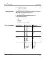
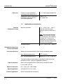
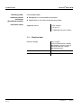
1
Operating manual VisoTurb® 700 IQ VisoTurb® 700 IQ SW VisoTurb 700 IQ VisoTurb 700 IQ SW IQ SENSOR NET turbidity / suspended solids sensor ba76039e01 01/2012 VisoTurb® 700 IQ (SW) Note For the most recent version of the manual, please visit www.ysi.com. Contact Copyright 2 YSI 1725 Brannum Lane Yellow Springs, OH 45387 USA Tel: +1 937-767-7241 800-765-4974 Email: [email protected] Internet: www.ysi.com © 2012 Xylem Inc. ba76039e01 01/2012 VisoTurb® 700 IQ (SW) Contents VisoTurb® 700 IQ (SW) - Contents 1 Overview . . . . . . . . . . . . . . . . . . . . . . . . . . . . . . . . . . . . 1-1 1.1 1.2 1.3 1.4 2 Safety instructions . . . . . . . . . . . . . . . . . . . . . . . . . . . . 2-1 2.1 2.2 3 3.3 3.4 01/2012 Measuring operation . . . . . . . . . . . . . . . . . . . . . . . . . . . 4-1 Calibration . . . . . . . . . . . . . . . . . . . . . . . . . . . . . . . . . . . 4-2 4.2.1 General information . . . . . . . . . . . . . . . . . . . . . . 4-2 4.2.2 Application offset . . . . . . . . . . . . . . . . . . . . . . . . 4-3 4.2.3 User calibration for measuring the total suspended solids (g/l TSS) . . . . . . . . . . . . . . . . 4-4 Maintenance, cleaning, accessories . . . . . . . . . . . . . 5-1 5.1 5.2 5.3 ba76039e01 Scope of delivery . . . . . . . . . . . . . . . . . . . . . . . . . . . . . . 3-1 Installation . . . . . . . . . . . . . . . . . . . . . . . . . . . . . . . . . . . 3-1 3.2.1 General information . . . . . . . . . . . . . . . . . . . . . . 3-1 3.2.2 Flow direction . . . . . . . . . . . . . . . . . . . . . . . . . . 3-2 3.2.3 Sensor angle . . . . . . . . . . . . . . . . . . . . . . . . . . . 3-2 3.2.4 Sensor orientation . . . . . . . . . . . . . . . . . . . . . . . 3-3 3.2.5 Distances from the ground and wall . . . . . . . . . 3-4 Installation examples . . . . . . . . . . . . . . . . . . . . . . . . . . . 3-5 3.3.1 Measuring in an open basin or channel (range > 100 FNU) . . . . . . . . . . . . . . . . . . . . . . 3-5 3.3.2 Measuring in an open channel (range > 100 FNU) . . . . . . . . . . . . . . . . . . . . 3-6 3.3.3 Measurement in pipelines . . . . . . . . . . . . . . . . . 3-7 Commissioning / Readiness for measuring . . . . . . . . . . 3-9 3.4.1 Connect the sensor . . . . . . . . . . . . . . . . . . . . . . 3-9 3.4.2 Setting table VisoTurb® 700 IQ (SW) . . . . . . . 3-11 Measuring . . . . . . . . . . . . . . . . . . . . . . . . . . . . . . . . . . . 4-1 4.1 4.2 5 Authorized use . . . . . . . . . . . . . . . . . . . . . . . . . . . . . . . . 2-2 General safety instructions . . . . . . . . . . . . . . . . . . . . . . . 2-2 Commissioning . . . . . . . . . . . . . . . . . . . . . . . . . . . . . . 3-1 3.1 3.2 4 How to use this component operating manual . . . . . . . . 1-1 Structure of the VisoTurb® 700 IQ (SW) turbidity sensor 1-2 Recommended fields of application . . . . . . . . . . . . . . . . 1-2 Features of the VisoTurb® 700 IQ (SW) . . . . . . . . . . . . . 1-3 General information . . . . . . . . . . . . . . . . . . . . . . . . . . . . 5-1 Cleaning the sensor shaft and sapphire disc . . . . . . . . . 5-1 Accessories . . . . . . . . . . . . . . . . . . . . . . . . . . . . . . . . . . 5-3 0-1 VisoTurb® 700 IQ (SW) Contents 6 What to do if ... . . . . . . . . . . . . . . . . . . . . . . . . . . . . . . . 6-1 7 Technical data . . . . . . . . . . . . . . . . . . . . . . . . . . . . . . . 7-1 7.1 7.2 7.3 7.4 8 Contact Information . . . . . . . . . . . . . . . . . . . . . . . . . . . 8-1 8.1 8.2 9 Ordering & Technical Support . . . . . . . . . . . . . . . . . . . .8-1 Service Information . . . . . . . . . . . . . . . . . . . . . . . . . . . . .8-1 Indexes . . . . . . . . . . . . . . . . . . . . . . . . . . . . . . . . . . . . . 9-1 9.1 9.2 0-2 Measuring characteristics . . . . . . . . . . . . . . . . . . . . . . . .7-1 Application characteristics . . . . . . . . . . . . . . . . . . . . . . .7-2 General data . . . . . . . . . . . . . . . . . . . . . . . . . . . . . . . . . .7-3 Electrical data . . . . . . . . . . . . . . . . . . . . . . . . . . . . . . . . .7-4 Explanation of the messages . . . . . . . . . . . . . . . . . . . . .9-1 9.1.1 Error messages . . . . . . . . . . . . . . . . . . . . . . . . .9-1 9.1.2 Info messages . . . . . . . . . . . . . . . . . . . . . . . . . .9-2 Status info . . . . . . . . . . . . . . . . . . . . . . . . . . . . . . . . . . . .9-3 ba76039e01 01/2012 VisoTurb® 700 IQ (SW) Overview 1 Overview 1.1 How to use this component operating manual Structure of the IQ SENSOR NET operating manual IQ Sensor Net Operating Manual System Operating Manual (Ring Binder) IQ Sensor Operating Manual MIQ Module Operating Manual MIQ Terminal Operating Manual Component Operating Manuals Fig. 1-1 Structure of the IQ SENSOR NET operating manual The IQ SENSOR NET operating manual has a modular structure like the IQ SENSOR NET system itself. It consists of a system operating manual and the operating manuals of all the components used. Please file this component operating manual into the ring binder of the system operating manual. ba76039e01 01/2012 1-1 VisoTurb® 700 IQ (SW) Overview 1.2 Structure of the VisoTurb® 700 IQ (SW) turbidity sensor 1 2 3 4 Fig. 1-2 1 Shaft 2 Connection head 3 Optical measurement window 4 Sapphire disc with ultrasound cleaning system 1.3 VisoTurb® 700 IQ VisoTurb® 700 IQ SW Structure of the turbidity sensor (example: VisoTurb® 700 IQ) Recommended fields of application Stationary measurement of the turbidity or suspended solids concentration (total suspended solids - TSS) in water/wastewater applications. Stationary measurements in seawater and brackish water, aquaculture. The VisoTurb® 700 IQ (SW) is particularly well suited for applications in polluted measuring media, e.g. in wastewater treatment plants, thanks to its robust construction and its efficient ultrasound cleaning system. It provides very high measurement accuracy with low maintenance costs. 1-2 ba76039e01 01/2012 VisoTurb® 700 IQ (SW) Overview 1.4 Features of the VisoTurb® 700 IQ (SW) Turbidity measurement according to EN ISO 7027 The turbidity measurement in aqueous media with the VisoTurb® 700 IQ (SW) is conducted nephelometrically in accordance with EN ISO 7027. Total suspended solids measurement The turbidity/total suspended solids sensor can also be used to determine the total suspended solids content in the sample. The appropriate correlation for the given application can be determined via a reference measurement. After this adjustment, the turbidity value is converted into the concentration of total suspended solids. Ultrasound cleaning system The ultrasound cleaning system ensures low maintenance and longterm reliable measurement operation. The ultrasound source integrated in the sensor excites the sapphire disc at the tip to produce vibrations in the ultrasound range. The movement of the surface as a result of this prevents the growth of pollution in almost all cases and, thus, ensures reliable measured values during continuous operation. AutoRange function The AutoRange function selects the optimum resolution for the respective measured value from the enormously large measuring range (0 - 4000 FNU). SensCheck function This monitoring function that is integrated in the sensor is used to continually check the sensor function and to register any malfunctions caused by the measuring medium. The correct operation of the ultrasound cleaning system is also continuously monitored. ba76039e01 01/2012 1-3 Overview 1-4 VisoTurb® 700 IQ (SW) ba76039e01 01/2012 VisoTurb® 700 IQ (SW) Safety instructions 2 Safety instructions This component operating manual contains special instructions that must be followed during the operation of the VisoTurb® 700 IQ (SW) turbidity sensor. Thus, it is essential to read this component operating manual before carrying out any work using this sensor. In addition to this manual, the SAFETY chapter of the IQ SENSOR NET system operating manual must be followed. Always keep this component operating manual together with the system operating manual and any other component operating manuals in the vicinity of the IQ SENSOR NET system. Special user qualifications General safety instructions The turbidity sensor was developed for applications in online measurement - essentially in the field of wastewater treatment. Thus, we assume that the operators are familiar with the necessary precautions to take when dealing with chemicals as a result of their professional training and experience. Safety instructions in this operating manual are indicated by the warning symbol (triangle) in the left column. The signal word (e.g. "CAUTION") indicates the danger level: WARNING indicates instructions that must be followed precisely in order to prevent serious dangers to personnel. CAUTION indicates instructions that must be followed precisely in order to avoid slight injuries to personnel or damage to the instrument or the environment. Other labels Note indicates notes that draw your attention to special features. Note indicates cross-references to other documents, e.g. operating manuals. ba76039e01 01/2012 2-1 VisoTurb® 700 IQ (SW) Safety instructions 2.1 Authorized use The authorized use of the VisoTurb® 700 IQ (SW) comprises its use as a turbidity sensor in the IQ SENSOR NET. Please observe the technical specifications according to chapter 7 TECHNICAL DATA. Only operation according to the instructions in this operating manual is authorized. Any other use is considered to be unauthorized. Unauthorized use invalidates any claims with regard to the guarantee. CAUTION The sensor warms up during operation in the air. Consequently, pollution can collect in the vicinity of the measurement window due to the evaporation of liquid. Therefore, avoid any lengthy operation in the air. CAUTION Only connect and operate the sensor together with IQ SENSOR NET accessories. 2.2 General safety instructions The sensor left the factory in a safe and secure technical condition. Function and operational safety The failure-free function and operational safety of the sensor is only guaranteed if the generally applicable safety measures and the special safety instructions in this operating manual are followed during its use. The failure-free function and operational safety of the sensor is only guaranteed under the environmental conditions that are specified in chapter 7 TECHNICAL DATA. The specified temperature (chapter 7 TECHNICAL DATA) must be maintained during the operation and transport of the sensor. CAUTION The sensor may only be opened by specialists authorized by YSI. 2-2 ba76039e01 01/2012 VisoTurb® 700 IQ (SW) Safe operation Safety instructions If safe operation is no longer possible, the sensor must be taken out of operation and secured against inadvertent operation. Safe operation is no longer possible if the sensor: has been damaged in transport has been stored under adverse conditions for a lengthy period of time is visibly damaged no longer operates as described in this manual. If you are in any doubt, contact the supplier of your sensor. Obligations of the operator The operator of the sensor must ensure that the following rules and regulations are followed when dealing with hazardous substances: EEC directives for protective labor legislation National protective labor legislation Safety regulations Safety data sheets of the chemical manufacturer. ba76039e01 01/2012 2-3 Safety instructions 2-4 VisoTurb® 700 IQ (SW) ba76039e01 01/2012 VisoTurb® 700 IQ (SW) Commissioning 3 Commissioning 3.1 Scope of delivery VisoTurb® 700 IQ (SW) turbidity/total suspended solids sensor Operating manual 3.2 Installation 3.2.1 General information The measuring principle of the VisoTurb® 700 IQ (SW) (optical scattered light measurement) places particular requirements on the measurement location and on the installation of the sensor. In slightly turbid test samples (< 100 FNU), infrared light penetrates the test sample deeply. Thus, the measuring environment can have a significant effect on the measured value displayed. Light that is reflected or scattered by the ground or wall can strike the detector in the sensor and, thus, simulate higher turbidity or an increased level of total suspended solids. Direct sunlight can easily interfere with the measurement. Scattered light can be kept away from the measurement windows to a great extent by favorable positioning of the sensor. For this reason, the optimum installation position is especially important for measuring low turbidity values. Note Always maintain a distance of at least 10 cm from the ground and wall. The following factors affect the measurement: Inclination of the sensor (see section 3.2.3) Sensor orientation around its longitudinal axis (see section 3.2.4) Distances from the ground and wall (see section 3.2.5) Light-colored, heavily light-scattering surfaces in the measuring vessel (e.g. vessel inner surfaces) or in the measuring environment. Unfavorable geometry of the measuring vessel or unfavorable positioning of the sensor in the measuring vessel. Air bubbles in the test sample Spatial proximity of two optical sensors Very bright ambient light at the measuring location, e.g. direct sunlight in the open channel ba76039e01 01/2012 3-1 VisoTurb® 700 IQ (SW) Commissioning 3.2.2 Flow direction As a general rule, the sapphire disc should be positioned clearly against the current in flowing media (angle of attack approx. 20 to 45 °). Exception: If there are high quantities of foreign bodies with fibrous or large surfaces, as for example hairs, strings or leaves, it may be of advantage to incline the sensor in the direction of the flow so that the sapphire disc does not face the flow. 3.2.3 Sensor angle Marking 50 cm 0° Fig. 3-1 20 ° 10 cm 45 ° Effect of the sensor angle on scattering and reflection from the ground and walls Note Scattering and reflection are lowest at a sensor angle of 45° and at a minimum distance of 10 cm to the ground and walls (see section 3.2.5). Note At a sensor angle of 45°, keep a minimum distance of 50 cm in the direction of the infrared beam. 3-2 ba76039e01 01/2012 VisoTurb® 700 IQ (SW) Commissioning 3.2.4 Sensor orientation The sensor has a marking (arrow symbol on the shaft or glue dot on connection head). The infrared beam emerges from the front of the sensor at an angle of 45 ° in the direction opposite the marking. Marking in this direction 45 ° Infrared beam VisoTurb 700 IQ SW Fig. 3-2 Direction of the infrared beam relative to the marking The angle of incidence to the ground and walls can be affected by rotating the sensor around its longitudinal axis. The sensor should be turned so that as little light as possible that is scattered or reflected by the wall or ground strikes the measurement window again. ba76039e01 01/2012 3-3 VisoTurb® 700 IQ (SW) Commissioning 3.2.5 Distances from the ground and wall Note In cases of low turbidity (< 100 FNU), the effect of the measuring environment can simulate higher turbidity or an increased level of total suspended solids. The effect of the measurement environment can be reduced by ensuring the optimum conditions (see section 3.2.1). The following graphic indicates the minimum distances of the measurement windows to the ground or wall, which must be observed. The effect of the distances on the measured value was determined for various wall materials in the case of a sensor placed vertically to the wall in drinking water (see drawing). Fig. 3-3 Effect of ground and wall distances on the turbidity measurement Note At low levels of turbidity, a minimum distance of at least 10 cm must be kept from the ground or wall. Note If an optimum installation is not possible due to the structural conditions at the measuring location (e.g. in narrow pipelines), the effects of the measurement environment can be compensated by an application offset (see section 4.2.2). 3-4 ba76039e01 01/2012 VisoTurb® 700 IQ (SW) Commissioning 3.3 Installation examples As a rule, the VisoTurb® 700 IQ (SW) will measure interference-free when the distances and angles etc. specified are observed. However, interferences at the measuring location (see section 3.2.1) may require special adaptations of the installation. 3.3.1 Measuring in an open basin or channel (range > 100 FNU) Example: Outlet of the preclarification stage The turbidity sensor can be immersed in the sample using a pendulum mounting assembly, e.g. pendulum mounting assembly EH/P 170, (pay attention to the minimum immersion depth). Alternatively, the sensor can be suspended on a chain (e.g. with the EH/F 170 swing mounting assembly and EH/U 170 sensor holder). Make sure that the sensor cannot bump against any walls or obstacles. ba76039e01 01/2012 3-5 VisoTurb® 700 IQ (SW) Commissioning 3.3.2 Example: Outlet of a waste water treatment plant (open channel, wall material: concrete) Measuring in an open channel (range > 100 FNU) In an open channel, the sensor can be immersed in the sample using a wall mounting assembly, e.g. EH/W 170 wall mounting assembly, (please note the minimum immersion depth). Protect the measuring location and the environment against direct sunlight (sun shield or similar) Mount the sensor rigidly in the channel. At the same time, tilt the sensor approx. 20 to 45 ° against the direction of the flow. Install the sensor so that the marking on the sensor points towards the outlet of the channel. Marking in this direction 45 ° n io ct ire D of w flo Immersion depth min. 7 cm min. 10 cm min. 10 cm Gro min. 10 cm und Fig. 3-4 Turbidity sensor in the open channel with EH/W 170 fixture assembly for direct wall mounting. Note Interferences at the measuring location (see section 3.2.1) may require special adaptations of the installation. For exceptions to the direction of flow, see section 3.2.2 FLOW DIRECTION. 3-6 ba76039e01 01/2012 VisoTurb® 700 IQ (SW) Commissioning 3.3.3 Measurement in pipelines Note In cases of low turbidity (< 100 FNU), the effect of the measuring environment can simulate higher turbidity or an increased level of total suspended solids. The effect of the measurement environment can be reduced by ensuring the optimum conditions (see section 3.2.1). Note If an optimum installation is not possible due to the structural conditions at the measuring location (e.g. in narrow pipelines), the effects of the measurement environment can be compensated by an application offset (see section 4.2.2). If deposits occur on the pipe walls, the application offset should be repeated at regular intervals. Example: 45 ° pipe installation The pipe should be straight for a length of min. 50 cm beyond the installation location. Angled or tapered pipes can cause interference effects in the case of low turbidity. ADA-DF 9 Swivel nut Marking aid in this direction EBST 700-DU/N Direction of flow Infrared beam ca. 50 cm straight pipe Fig. 3-5 Turbidity sensor in the pipe using EBST 700-DU/N flow-thru adapter Fig. 3-5 shows the installation using the EBST 700-DU/N flow-thru adapter for installation in a straight pipeline (DN 50). The infrared beam is parallel to the pipeline axis and points in the opposite direction to the direction of flow. The marking on the sensor points towards the pipeline (see Fig. 3-5). Note Interferences at the measuring location (see section 3.2.1) may require special adaptations of the installation. For exceptions to the direction of flow, see section 3.2.2 FLOW DIRECTION. ba76039e01 01/2012 3-7 VisoTurb® 700 IQ (SW) Commissioning Example: 90 ° pipe installation Fig. 3-6 Turbidity sensor in the pipe (90 °) The following points must be observed for a right-angled installation in the pipe (Fig. 3-6): Rotate the sensor so that the marking on the sensor points in the direction of the pipe axis Select a position where the pipe diameter is as large as possible as the installation location (see section 3.2.5 DISTANCES FROM THE GROUND AND WALL). Before measuring, check whether an application offset is required in the case of lower turbidity values (see section 4.2.2). Marking aid 3-8 1 Connect the SACIQ (SW) sensor connection cable to the plug head connector of the sensor and screw it tight (see section 3.4.1). 2 Attach a marking aid (adhesive strips or similar) in the same position as the marking on the sensor to the plug head connector. ba76039e01 01/2012 VisoTurb® 700 IQ (SW) Commissioning Marking aid Marking Fig. 3-7 3 3.4 Marking aid Install the sensor in the flow-thru adapter with the aid of the ADA-DF 9 adapter (see operating manual of the adapter). To ensure the correct position, loosen the coupling ring on the EBST 700-DU/N somewhat and align the marking aid as shown in Fig. 3-5. Then, tighten the coupling ring. Commissioning / Readiness for measuring 3.4.1 Connect the sensor Connection cable A sensor connection cable of the SACIQ or SACIQ SW type is required to connect the sensor. The cable is available in different lengths. Compared to the standard model SACIQ, the SACIQ SW sensor connection cable is optimized regarding its corrosion resistance in seawater and brackish water and adapted for use in conjunction with the VisoTurb® 700 IQ SW. Information on this and other IQ SENSOR NET accessories is given in the YSI catalog and on the Internet. Note How to connect the SACIQ (SW) sensor connection cable to the terminal strip of an MIQ module is described in chapter 3 INSTALLATION of the IQ SENSOR NET system operating manual. Are the plug connections dry? ba76039e01 01/2012 Before connecting the sensor and sensor connection cable, please make sure that the plug connections are dry. If moisture gets into the plug connections, first dry the plug connections (dab them dry or blow them dry using compressed air). 3-9 VisoTurb® 700 IQ (SW) Commissioning Note Do not suspend the sensor on the sensor connection cable. Use a sensor holder or an armature. Information on this and other IQ SENSOR NET accessories is given in the YSI catalog and on the Internet. Connecting the sensor to the sensor connection cable 1 Take the protective caps off the plug connections of the sensor and the SACIQ sensor connection cable and keep them safe. 2 Plug the jack of the SACIQ (SW) sensor connection cable onto the plug head connector of the sensor. At the same time, rotate the socket so that the pin in the plug head connector (1) clicks into one of the two holes in the jack. 3 Then, screw the coupling ring (2) of the sensor connection cable onto the sensor up to the stop. SACIQ 2 1 Fig. 3-8 Connect the sensor Note The sensor is provided with a long-term stable factory calibration for turbidity measurement and is immediately ready to carry out measurements. 3 - 10 ba76039e01 01/2012 VisoTurb® 700 IQ (SW) Commissioning 3.4.2 Setting table VisoTurb® 700 IQ (SW) Setting Selection/values Explanation Measuring mode FNU – Turbidity unit Formazine Nephelometric Units NTU – Turbidity unit Nephelometric Turbidity Units TEF – Turbidity Unit Formazine mg/l SiO2 – Concentration of SiO2 in mg/l ppm SiO2 – Concentration of SiO2 in ppm g/l TSS – Conc. of total suspended solids in g/l (for details, see section 4.2.3). AutoRange Measuring ranges for the FNU measuring mode Measuring range 0 ... 0.400 FNU 0 ... 4.00 FNU 0 ... 40.0 FNU (AutoRange = automatic changeover of the measuring range) 0 ... 400 FNU 0 ... 4000 FNU AutoRange 0 ... 0.400 NTU 0 ... 4.00 NTU 0 ... 40.0 NTU Measuring range for the measuring mode NTU (AutoRange = automatic changeover of the measuring range) 0 ... 400 NTU 0 ... 4000 NTU AutoRange 0 ... 0.400 TEF 0 ... 4.00 TEF 0 ... 40.0 TEF Measuring range for the measuring mode TEF (AutoRange = automatic changeover of the measuring range) 0 ... 400 TEF 0 ... 4000 TEF AutoRange 0 ... 0.400 mg/l 0 ... 4.00 mg/l 0 ... 40.0 mg/l Measuring range for the measuring mode mg/l SiO2 (AutoRange = automatic changeover of the measuring range) 0 ... 400 mg/l 0 ... 4000 mg/l ba76039e01 01/2012 3 - 11 VisoTurb® 700 IQ (SW) Commissioning Setting Selection/values Explanation AutoRange Measuring range for the measuring mode ppm SiO2 0 ... 0.400 ppm 0 ... 4.00 ppm 0 ... 40.0 ppm (AutoRange = automatic changeover of the measuring range) 0 ... 400 ppm 0 ... 4000 ppm AutoRange 0 ... 0.400 mg/l 0 ... 4.00 mg/l 0 ... 40.0 mg/l Measuring range for the measuring mode g/l TSS (AutoRange = automatic changeover of the measuring range) 0 ... 400 mg/l 0 ... 4.00 g/l 0 ... 40.0 g/l 0 ... 400 g/l TSS range Adjustment values from the reference measurement for determining the amount of total suspended solids. Only displayed if the g/l TSS measuring mode was selected (for details, see section 4.2.3). TSS value Turbidity range Turbidity value Signal averaging 1 ... 600 secs Response time of the signal filter. Depending on the sample matrix, the measured values may oscillate more or less (e.g. due to foreign bodies or air bubbles). The signal filter reduces the limits of variation of the measured value. The signal filter is characterized by the signal averaging time. This is the time after which 90 % of a signal change is displayed. Application offset -20.00 ... +20.00 (units depend on measuring mode) Correction value for compensation of environmentally-dependent interferences. The value is added to the measured value (for details, see section 4.2.2). Ultrasonic cleaning On Off Pulse Switch on or off the ultrasound cleaning function (Pulse = pulse operation). Save and quit 3 - 12 The system confirms the saving of the settings and the display switches to the next higher level. ba76039e01 01/2012 VisoTurb® 700 IQ (SW) Setting Quit Selection/values Explanation The display switches to the next higher level without saving the new settings. Carrying out settings ba76039e01 Commissioning 01/2012 Switch to the main settings menu from the measured value display with s. Then navigate to the setting menu (setting table) of the sensor. The exact procedure is described in the relevant IQ SENSOR NET system operating manual. 3 - 13 Commissioning 3 - 14 VisoTurb® 700 IQ (SW) ba76039e01 01/2012 VisoTurb® 700 IQ (SW) Measuring 4 Measuring The turbidity measurement in aqueous media with the VisoTurb® 700 IQ (SW) is conducted nephelometrically in accordance with EN ISO 7027. The turbidity/total suspended solids sensor can also be used to determine the total suspended solids content in the sample. The appropriate correlation for the given application can be determined via a reference measurement. After this adjustment, the turbidity value is converted into the concentration of total suspended solids. 4.1 Measuring operation 1 Immerse the sensor in the sample. 2 Read the measured value on the terminal of the IQ SENSOR NET system. Note Large differences between the temperature of the sensor and sample can falsify the measurement result. Thus, as a precaution during commissioning, wait for 15 minutes before using the measured value. Note The allowed temperature of the measuring medium is 0 ... 60 °C. The ultrasound cleaning system switches itself off automatically if the temperature of the measuring medium is above 40 °C. When the temperature decreases below 40 °C, it switches itself on again. The switching off above 40 °C prevents an overheating, for example if the minimum immersion depth of the sensor is not maintained. ba76039e01 01/2012 4-1 VisoTurb® 700 IQ (SW) Measuring Why calibrate? 4.2 Calibration 4.2.1 General information The following factors can change with time and affect the measurement results: the optical characteristics, e.g. color and particle size, and the density of the measuring medium (e.g. dependent on the season) the conditions at the measuring location (e.g. due to growing deposits on the ground and walls) The effect of the measurement environment can be reduced by ensuring the optimum conditions (see section 3.2.1) and can be compensated by an application offset (see section 4.2.2). For measurements of the total suspended solids, a user calibration is always required (see section 4.2.3). When to calibrate? A new user calibration is required if there is any change of the characteristics of the measuring medium or any change of the environment at the measuring location. Note Values of the user calibration that have been entered are saved in the controller and thus assigned to the measuring location (not to the sensor). Therefore, if the sensor is exchanged, no new user calibration is required. How is a calibration carried out? The actual level of total suspended solids of your measuring medium is determined by a reference measurement (e.g. gravimetric according to DIN 38414). If the reference measurements do not deviate from the optically determined measured value of the VisoTurb® 700 IQ (SW), the sensor is already optimally adapted to the measuring situation. If the reference measurements do deviate from the optically determined measured value of the VisoTurb® 700 IQ (SW), proceed as follows: Optimize the conditions at the measuring location (see section 3.2.1) Perform a user calibration (see section 4.2.3) if you measure the total suspended solids. Perform an application offset (see section 4.2.2), if the measuring environment affects the measured values 4-2 ba76039e01 01/2012 VisoTurb® 700 IQ (SW) Measuring 4.2.2 Application offset In an optimum installation (sufficient distance to the walls, walls made of dark material), the effect of the measurement environment is negligibly small. If an optimum installation is not feasible due to local circumstances, interference effects can be compensated by a measured value correction. Note Depending on the test sample, the optical characteristics of the vessel inner surface can change greatly with time (biological films, lime deposits). This can affect the turbidity measurement. Repeat the application offset from time to time as well as to check the effect of the surfaces if excessive turbidity values are suspected. Determining the correction value The determination of the correction value can be carried out using normal drinking water. Two measurements are performed: 1. Measurement in an environment that is as ideal as possible (reference value). 2. Measurement in the actual measurement environment. The correction value is calculated from the two measurements as follows (the correction value is usually negative): Correction value = turbidity value (ideal) - turbidity value (real) Entering the correction value for the measurement Ideal measurement environment The correction value is entered in the setting table of the turbidity sensor in the Application offset field (see section 3.4.2). An ideal measurement environment for the application offset can be set up with the following simple accessories: Bucket made of black plastic, with a capacity of at least 10 l Holding device for the sensor, e. g. laboratory stand Shading against direct sunlight (cardboard or similar). Position the sensor as shown in the following diagram: ba76039e01 01/2012 4-3 VisoTurb® 700 IQ (SW) Measuring Marking in this direction approx. 10 cm approx. 20 cm Fig. 4-1 4.2.3 Ideal measurement environment for the application offset User calibration for measuring the total suspended solids (g/l TSS) The turbidity values of the TSS measurement are converted into FNU units for the concentration of dry substance. The g/l TSS measuring mode displays the turbidity value as a secondary measured value in FNU. The correlation between the FNU units and the concentration of dry substance is achieved via a user calibration. At the point of time of the user calibration, the test sample should be in a state representative of the later measurement (type and amount of total suspended solids, coloration, etc.). The results of the user calibration are input manually in the setting table of the VisoTurb® 700 IQ (SW) (see section 3.4.2). Setting for total suspended solids measurement 4-4 1 Bring the sensor into the measuring position. 2 In the setting table of the turbidity sensor, select the g/l TSS measuring mode and the AutoRange measuring range (see section 3.4.2). 3 Switch to the measured value display with m. 4 When the measured value is stable, read and record the FNU value (secondary measured value). 5 If possible, take a sample at the same time as the turbidity measurement and, if possible, directly at the measurement windows. ba76039e01 01/2012 VisoTurb® 700 IQ (SW) Measuring 6 Determine and note the concentration of total suspended solids in the sample according to a reference procedure (e.g. gravimetric according to DIN 38414). 7 Switch to the setting table of the turbidity sensor. 8 Select the value range for the total suspended solids contents determined during the reference measurement in the TSS range field. 9 Select the value range for the turbidity determined during the reference measurement in the Turbitity range field. 10 Enter the values for the concentration of total suspended solids and turbidity obtained from the reference measurement. Note To measure the TSS contents, both values of the reference measurement (total suspended solids content and the corresponding turbidity value) must be entered. The following table shows the possible settings: Setting Selection/values Explanation TSS range 0 ... 0.400 mg/l Range for entering the total suspended solids contents. The setting range is subdivided because it is so large. 0 ... 4.00 mg/l 0 ... 40.0 mg/l 0 ... 400 mg/l 0 ... 4.00 g/l 0 ... 40.0 g/l 0 ... 400 g/l Select the smallest possible range in order to enter the value in the TSS value field as precisely as possible. Example: Concentration of total suspended solids = 35.76 mg/l – Smallest possible settings range: 0 ... 40.0 mg/l. – Entry in the TSS value field: 35.8 mg/l TSS value ba76039e01 01/2012 Concentration of total suspended solids in g/l TSS as it was determined using the reference procedure. The input precision depends on the setting in the TSS range field. 4-5 VisoTurb® 700 IQ (SW) Measuring Setting Selection/values Explanation Turbidity range 0 ... 0.400 FNU Range for the entry of the turbidity value. 0 ... 4.00 FNU 0 ... 40.0 FNU 0 ... 400 FNU 0 ... 4000 FNU Select the smallest possible range in order to enter the turbidity value in the Turbidity value field as precisely as possible. Example: Reading of the turbidity value= 38.2 FNU – Smallest possible settings range: 0 ... 40.0 FNU. – Entry in the Turbidity value field: 38.2 FNU Turbidity value Turbidity value as it was determined with the turbidity sensor. The input precision depends on the setting in the Turbidity range field. 11 Make the sensor settings with d and confirm each of them with g. 12 Select the Save and quit menu item with d and confirm with g. The new settings are stored in the sensor. The turbidity sensor is calibrated for the measurement of total suspended solids. Note The total suspended solids measurement is even more precise, the better the current status of the sample corresponds to the status at the time of the user calibration. If there is a fundamental change of the characteristics of the sample, a new user calibration may be necessary. 4-6 ba76039e01 01/2012 VisoTurb® 700 IQ (SW) Maintenance, cleaning, accessories 5 Maintenance, cleaning, accessories 5.1 General information WARNING Contact with the sample can be dangerous for the user! Depending on the type of sample, suitable protective measures must be taken (protective clothing, protective goggles, etc.). The VisoTurb® 700 IQ (SW) sensor does not usually require any maintenance. The continuously running ultrasound system prevents the accumulation of pollution in almost all cases. Note We recommend cleaning the shaft and the sapphire disc if the sensor has remained in the sample in a non-operative condition for any lengthy period of time. 5.2 Cleaning the sensor shaft and sapphire disc During normal operation (e.g. municipal wastewater), cleaning is recommended: if there is any pollution (according to visual check) if the sensor was not in operation for a lengthy period of time but was immersed in the measuring medium if the measured values are suspected of being incorrect (usually too low) if the SensCheck message appears in the log book Cleaning agents Contamination Cleaning agents Sludge and loosely adhering dirt or biological films Soft cloth or soft brush, warm tap water with detergent Salt and / or lime deposits Acetic acid (volume percentage = 20 %), soft cloth or soft sponge CAUTION Acetic acid irritates the eyes and the skin. When handling acetic acid, always wear protective gloves and protective goggles. ba76039e01 01/2012 5-1 VisoTurb® 700 IQ (SW) Maintenance, cleaning, accessories Note We do not recommend to unscrew the sensor from the sensor connection cable when cleaning the sensor shaft and membrane. Otherwise, moisture and/or dirt can get into the plug connection where they can cause contact problems. If you would like to disconnect the sensor from the sensor connection cable, please note the following points: Before disconnecting the sensor from the SACIQ (SW) sensor connection cable, remove any larger pieces of contamination from the sensor, particularly in the area of the plug connection (brush it off in a bucket of tap water, wash it off with a hose or wipe it off with a cloth). Unscrew the sensor from the SACIQ (SW) sensor connection cable. Always place a protective cap on the sensor plug head connector and on the SACIQ (SW) sensor connection cable so that no moisture or dirt can get into the contacting surfaces. In corrosive environments, close the socket of the sensor connection cable with the screwable SACIQ-Plug when it is dry in order to protect the electrical contacts from corrosion. The protective plug is available as an accessory (see section 5.3 ACCESSORIES). It is included in the standard scope of delivery of the SACIQ SW sensor connection cable. CAUTION The sensor warms up during operation in the air. Consequently, pollution can collect in the vicinity of the measurement window due to the evaporation of liquid. Therefore, avoid any lengthy operation in the air. Cleaning 5-2 1 Pull the sensor out of the sample. 2 Remove any coarse pollution from the sensor (by brushing it off in a bucket of tapwater, spraying it off with a hose or wiping with a cloth). 3 Clean the sensor shaft and the sapphire disc as specified in the section CLEANING AGENTS. 4 Then, rinse it thoroughly with tap water. ba76039e01 01/2012 VisoTurb® 700 IQ (SW) Maintenance, cleaning, accessories 5.3 Accessories Description Model Order no. Screwable plug for sensor connection cable SACIQ-Plug 480 065Y Note Information on other IQ SENSOR NET accessories is given in the YSI catalog and on the Internet. ba76039e01 01/2012 5-3 Maintenance, cleaning, accessories 5-4 VisoTurb® 700 IQ (SW) ba76039e01 01/2012 VisoTurb® 700 IQ (SW) What to do if ... 6 What to do if ... The sensor automatically switches itself on and off periodically after commissioning Cause Remedy – The available power is sufficient for the initialization of the sensor, but not for the operation of the cleaning system. As soon as this is switched on, communication with the controller is interrupted. – Install another power supply module as close as possible to the VisoTurb® 700 IQ (SW) Mechanical damage to the sensor Cause Remedy Display of OFL Cause Remedy – Measuring range exceeded – See log book Cause Remedy – Measured value invalid – See log book Cause Remedy – Gas bubbles in the medium are in front of the sapphire disc – Check the installation position of the sensor (see section 3.2 and section 3.3) – Signal averaging time too short for low values of turbidity – Increase signal averaging time Cause Remedy – Sapphire disc polluted – Clean sapphire disc (see section 5.2) Display of "----" Measured value fluctuating heavily Measured values too low ba76039e01 01/2012 – Return the sensor 6-1 VisoTurb® 700 IQ (SW) What to do if ... Measured values too high Cause Remedy – Gas bubbles in the medium are in front of the sapphire disc – Check the installation position of the sensor (see section 3.2 and section 3.3) – Light scattering on the walls – Check the installation position of the sensor (see section 3.2 and section 3.3) – If necessary, compensate for effects that cannot be removed with the aid of the application offset function Measured value flashes Cause Remedy – Maintenance condition is switched on – if the maintenance condition was switched on manually (e.g. by pressing the c key): Switch off the maintenance condition manually in the Display/Options menu (see system operating manual) – if the maintenance condition was switched on automatically (e.g. by the cleaning system): The maintenance condition will be terminated automatically 6-2 ba76039e01 01/2012 VisoTurb® 700 IQ (SW) Measuring principle Technical data 7 Technical data 7.1 Measuring characteristics Procedure for measuring scattered light measurement in accordance with EN ISO 7027 (DIN EN 27027 or ISO 7027): 90 ° measuring angle Measurement in formazine nephelometric units, FNU Conversion of the values to: – NTU – TEF – mg/l SiO2 – ppm SiO2 – g/l TSS (total suspended solids) Measuring ranges and resolutions ba76039e01 01/2012 Measuring mode Measuring ranges Resolution FNU, NTU, TEF 0 ... 0.400 0 ... 4.00 0 ... 40.0 0 ... 400 0 ... 4000 0.001 0.01 0.1 1 1 mg/l SiO2 0 ... 0.400 0 ... 4.00 0 ... 40.0 0 ... 400 0 ... 4000 0.001 0.01 0.1 1 1 ppm SiO2 0 ... 0.400 0 ... 4.00 0 ... 40.0 0 ... 400 0 ... 4000 0.001 0.01 0.1 1 1 TSS 0 ... 0.400 mg/l 0 ... 4.00 mg/l 0 ... 40.0 mg/l 0 ... 400 mg/l 0 ... 4.00 g/l 0 ... 40.0 g/l 0 ... 400 g/l 0.001 mg/l 0.01 mg/l 0.1 mg/l 1 mg/l 0.01 g/l 0.1 g/l 1 g/l 7-1 VisoTurb® 700 IQ (SW) Technical data Accuracy Process variation coefficient according to DIN 38402 part 51 < 1 % in the range to 2000 FNU Repeatability limit or repeatability according to DIN ISO 5725 or DIN 1319 respectively < 0.015 % or min. 0.006 FNU. 7.2 Allowed temperature range Application characteristics Measuring medium 0 °C ... + 60 °C (32 ... 140 °F) Operation with ultrasound cleaning system possible up to 40 °C Note: The ultrasound cleaning system automatically switches off and on again. The switching off above 40 °C prevents an overheating, for example if the minimum immersion depth of the sensor is not maintained. Storage/transport Allowed pH range of the measuring medium Pressure resistance - 5 °C ... + 65 °C (23 ... 149 °F) 4 ... 12 Sensor with connected SACIQ (SW) sensor connection cable: Max. allowed overpressure 106 Pa (10 bar) Max. allowed underpressure temporarily 5 x 10⁴ Pa (0,5 bar) The sensor fulfills all requirements according to article 3(3) of the directive 97/23/EC ("pressure equipment directive"). Type of protection Sensor with connected SACIQ (SW) sensor connection cable: IP 68, 10 bar (106 Pa) Depth of immersion Operating position Fields of application 7-2 min. 10 cm; max. 100 m depth see section 3.2 INSTALLATION Water and wastewater monitoring ba76039e01 01/2012 VisoTurb® 700 IQ (SW) Technical data 7.3 Dimensions General data VisoTurb 700 IQ: 365 40.0 Socket SACIQ... VisoTurb 700 IQ SW: 365 32 40.0 Weight (without sensor connection cable) Connection technique Material 204 Socket SACIQ... 59.5 VisoTurb® 700 IQ approx. 990 g VisoTurb® 700 IQ SW approx. 1420 g Connection using SACIQ (SW) sensor connection cable Shaft: – VisoTurb® 700 IQ V4A stainless steel 1.4571 * – VisoTurb® 700 IQ SW POM Sensor head: – VisoTurb® 700 IQ V4A stainless steel 1.4571 * – VisoTurb® 700 IQ SW Titanium Measurement window Sapphire Plug head connector housing POM Plug, 3-pole ETFE (blue) Tefzel® * Stainless steel can be susceptible to corrosion at chloride concentrations of ≥ 500 mg/l and more. We recommend to use SW sensors for applications in such test solutions. ba76039e01 01/2012 7-3 VisoTurb® 700 IQ (SW) Technical data Cleaning system Automatic sensor monitoring (SensCheck function) Instrument safety Ultrasound principle Recognition of a measurement malfunction Identification of any failure of the cleaning system Applicable norms – EN 61010-1 – UL 3111-1 – CAN/CSA C22.2 No. 1010.1 7.4 7-4 Electrical data Nominal voltage max. 24 VDC via the IQ SENSOR NET (details see chapter TECHNICAL DATA of the IQ SENSOR NET system operating manual) Power consumption 1.5 W Protective class III ba76039e01 01/2012 VisoTurb® 700 IQ (SW) Contact Information 8 Contact Information 8.1 Ordering & Technical Support Telephone: (800) 897-4151 (937) 767-7241 Monday through Friday, 8:00 AM to 5:00 PM ET Fax: (937) 767-1058 Email: [email protected] Mail: YSI Incorporated 1725 Brannum Lane Yellow Springs, OH 45387 USA Internet: www.ysi.com When placing an order please have the following information available: YSI account number (if available) Model number or brief description Quantity 8.2 Name and Phone Number Billing and shipping address Purchase Order or Credit Card Service Information YSI has authorized service centers throughout the United States and Internationally. For the nearest service center information, please visit www.ysi.com and click ‘Support’ or contact YSI Technical Support directly at 800-897-4151. When returning a product for service, include the Product Return form with cleaning certification. The form must be completely filled out for an YSI Service Center to accept the instrument for service. The Product Return form may be downloaded at www.ysi.com and clicking on the ‘Support‘ tab. ba76039e01 01/2012 8-1 Contact Information 8-2 VisoTurb® 700 IQ (SW) ba76039e01 01/2012 VisoTurb® 700 IQ (SW) Indexes 9 Indexes 9.1 Explanation of the messages This chapter contains a list of all the message codes and related message texts that can occur in the log book of the IQ SENSOR NET system for the VisoTurb® 700 IQ (SW) sensor. Note Information on the contents and structure of the log book and the structure of the message code is given in the LOG BOOK chapter of the IQ SENSOR NET system operating manual. Note All message codes of the VisoTurb® 700 IQ (SW) end with the number "341". 9.1.1 Error messages Message code Message text EA2341 Sensor temperature too high! * Check process and application EA3341 Sensor temperature too low! * Check process and application EA6341 Meas. range exceeded or undercut * Check process * Select other meas. range * Submerse sensor in sample * Select bubble-free spot for measurement * Remove any foreign matter from sensor * Avoid influence of large foreign matter * Clean sensor * Increase signal average time EA7341 Ultrasound cleaning system switched off * Check sample temperature * Submerse sensor in sample EI1341 Operational voltage too low * Check installation and cable lengths, Follow installation instructions * Power unit(s) overloaded, add power unit(s) * Defective components, replace components ba76039e01 01/2012 9-1 VisoTurb® 700 IQ (SW) Indexes Message code Message text EI2341 Operational voltage too low, no operation possible * Check installation and cable lengths, Follow installation instructions * Power unit(s) overloaded, add power unit(s) * Check terminal and module connections * Defective components, replace components ES1341 Component hardware defective * Contact service ESD341 SensCheck: Measurement interfered * Submerse sensor in sample * Select bubble-free spot for measurement * Remove any foreign matter from sensor * Avoid influence of large foreign matter * Clean sensor * Increase signal average time ESE341 SensCheck: Ultrasound cleaning system has failed * Return sensor for repair 9.1.2 Info messages Message code Message text IA1341 Ultrasound cleaning system switched on * Check sensor visually * Clean sensor if necessary 9-2 ba76039e01 01/2012 VisoTurb® 700 IQ (SW) Indexes 9.2 Status info The status info is a piece of coded information about the current state of a sensor. Each sensor sends this status info to the controller. The status info of sensors consists of 32 bits, each of which can have the value 0 or 1. Status info, general structure 0 1 2 3 4 5 6 7 8 9 10 11 12 13 14 15 1 0 0 0 0 0 0 0 0 0 0 0 0 0 0 0 (general) 0 0 0 0 0 0 0 0 0 0 0 0 0 0 0 0 (internal) 16 17 18 19 20 21 22 23 24 25 26 27 28 29 30 31 The bits 0 - 15 are reserved for general information. The bits 16 - 21 are reserved for internal service information. You obtain the status info: via a manual query in the menu, Einstellungen/Setup/Service/List of all components (see system operating manual) via an automated query – of a superordinate process control (e. g. when connected to the Profibus) – of the IQ Data Server (see operating manual of the IQ SENSOR NET software pack) Note The evaluation of the status info, e.g. in the case of an automated query, has to be made individually for each bit. VisoTurb® 700 IQ (SW) Status info ba76039e01 01/2012 Status bit Explanation Bit 0 Component hardware defective Bit 1 SensCheck: Measurement interfered Bit 2 SensCheck: Ultrasound cleaning system has failed Bit 3-31 - 9-3 Indexes 9-4 VisoTurb® 700 IQ (SW) ba76039e01 01/2012 1725 Brannum Lane Yellow Springs, Ohio 45387 USA +1 937-767-7241 800-765-4974 (US) FAX (937) 767-1058 Email: [email protected] Internet: www.ysi.com