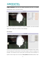
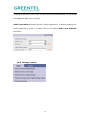
1
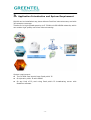
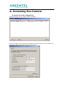
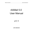
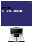
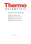
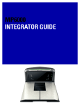
GREENTEL HSUPA PTZ Network Camera
and
HSUPA Fixed Network Camera
User Manual
For MX100 and MX101
-1-
ANNOUNCEMENTS ......................................................................................................................... 3
1. CAMERA INTRODUCTION..................................................................................................... 5
1.1 FEATURES: ................................................................................................................................... 5
1.2 TECHNICAL SPECIFICATIONS: .................................................................................................... 6
1.3 PRODUCT KIT: ............................................................................................................................. 6
2. HARDWARE INTRODUCTION ............................................................................................. 7
2.1 MX100 FRONT PANELS .............................................................................................................. 7
2.2 MX100 BACK PANELS ................................................................................................................ 7
2.3 MX101 FRONT PANELS .............................................................................................................. 8
2.4 MX101 BACK PANELS ................................................................................................................ 8
2.5 INTERFACE (FROM UP TO DOWN) ............................................................................................... 9
2.6 LED INDICATORS......................................................................................................................... 9
3. APPLICATION INTRODUCTION AND SYSTEM REQUIREMENT...................... 10
4. ACCESSING THE CAMERA .................................................................................................. 11
4.1 SEARCH IP AND PC CONFIGURATION ...................................................................................... 11
4.2 LOGIN ......................................................................................................................................... 12
4.3 REAL-TIME .................................................................................................................................. 12
4.4 REPLAY........................................................................................................................................ 15
4.5 SETTINGS ................................................................................................................................... 16
4.5.1 SETTINGS->BASIC................................................................................................................ 17
4.5.2 SETTINGS->NETWORK ......................................................................................................... 19
4.5.3 SETTINGS->3G..................................................................................................................... 22
4.5.4 SETTINGS->3G..................................................................................................................... 26
4.5.5 SETTINGS->ALARM............................................................................................................... 30
4.5.6 SETTINGS->SERVER STORAGE ............................................................................................ 33
APPENDIX A: PORT INTRODUCTION ................................................................................ 36
APPENDIX B: GPIO TERMINAL APPLICATION ............................................................ 37
5. SUPPORT ..................................................................................................................................... 38
-2-
Announcements
Thank user for choosing our product. GREENTEL MX100 and MX101 are wireless
broadband HSUPA H.264/MJPEG Network Cameras.
GREENTEL MX100 and MX101 built in HSUPA cellular module, wireless upload speed
up to 5.76Mbps.
Please read this manual carefully before using the product.
Important Safety Information
This product is not intended for use in the following
circumstances
•
Area(s) where radio transmission equipment (such as cell phone) are not
permitted.
•
Hospitals, health care facilities and area(s) where cell phones are restricted
by law.
•
•
•
•
Gas stations, fuel storage and places where chemical are stored.
Chemical plants or places with potential explosion hazard.
Any metal surface that may weaken the radio signal level.
The appliance is intended to be installed in restricted access location. Only
service person or authorized person is allowed to access.
Copyright Announcement
Copyright GREENTEL LIMITED 2010.
All rights reserved.
Reproduction, transfer, distribution or storage of part or all of the contents in this
document in any form without the prior written permission of GREENTEL is
prohibited.
Information Edition: GL – A – MX100 – 1.0
-3-
WEEE Notice
The Directive on Waste Electrical and Electronic Equipment (WEEE), which entered
into force as European law on 13th February 2003, resulted in a major change in the
treatment of electrical equipment at end-of-life.
The purpose of this Directive is, as a first priority, the prevention of WEEE, and in
addition, to promote the reuse, recycling and other forms of recovery of such wastes
so as to reduce disposal.
The WEEE logo (shown at the left) on the product or on its box indicates that this
product must not be disposed of or dumped with userr other household waste. User
are liable to dispose of all userr electronic or electrical waste equipment by
relocating over to the specified collection point for recycling of such hazardous
waste. Isolated collection and proper recovery of userr electronic and electrical
waste equipment at the time of disposal will allow us to help conserving natural
resources. Moreover, proper recycling of the electronic and electrical waste
equipment will ensure safety of human health and environment. For more
information about electronic and electrical waste equipment disposal, recovery, and
collection points, please contact userr local city centre, household waste disposal
service, shop from where user purchased the equipment, or manufacturer of the
equipment.
-4-
1. Camera Introduction
GREENTEL MX100 is a wireless broadband HSUPA PTZ H.264/MJPEG Network
Camera.
GREENTEL MX101 is a wireless broadband HSUPA Fixed H.264/MJPEG Network
Camera.
GREENTEL MX100 and MX101 built in HSUPA cellular module, wireless upload
speed up to 5.76Mbps.
Applications such as in the CAR, CAMPING, BOAT, BABY CARE and SHOW.
1.1 Features:
Access IP Camera via 3G HSUPA
HSUPA upload speed up to 5.76Mbps, enable real-time high quality video
streaming
H.264/MJEPG Codec for resolution
WEB configuration for setup or remote monitoring
Multi-levels password for protection from web
Two-way audio via G.711 audio compression external audio input/output
Supports RTSP, VLC (PS/TS) Stream Media protocol
Alarm triggered by GPIO, motion detection date, time, video lost
File upload via FTP/Email; notification via Email/SMS
Local storage to SD card
Supports TCP/IP. UDP, ICMP, DHCP, NTP, DNS, DDNS, SMTP, FTP, HTTP,
PPPoE, UPnP, RTP, RTSP, RTCP
Free management software supports up to 100 channels
Video broadcast software enables video broadcast to either private or public
IP
SDK available for application development and system integration
Camera:
Image sensor: 1/3” SONY CCD, 420/520 TVL
Built in infrared LEDs up to 16ft (5m) for night vision (MX100 only)
Day/Night: Auto
Lens: CS-mount, 8mm, f=2.0; angle of view, horizontal: 42
Minimum Illumination: 0.5 Lux (F1.2, 5600K)
Pan: 0° to 355°, Tilt: 0° to 90°, Speed: 15°/s (MX100 only)
Auto IRIS: Support
Scan System: Interlace
Video/Audio:
Video Compression: H.264/MJPEG
Frame Rate: 1 to 30 f/s
-5-
Resolution: D1, Half D1, CIF, QCIF
Video Stream: Bit-rate Range: 32K to 4Mbps (H.264)
Image Settings: Brightness, Contrast, Saturation, Hue Exposal control, AES
(1/60(1/50) to 1/120000 S.) AGC, AWB, BLC, Privacy mask, Motion
Detection
Video H-REV: Support horizontal reverse
Video V-REV: Support vertical reverse
Audio Compression: G.711
Audio Stream: Two-way audio, broadcast
Audio Input/Output: Mic input, headphone output
1.2 Technical Specifications:
Hardware: CPU HI3512, FLASH 8M, DRAM 128M
O/S: Linux
HSUPA/HSDPA/UMTS/WCDMA: 850/900/1900/2100 MHz
HSUPA: up to 7.2Mbps downlink, 5,76Mbps uplink
HSDPA: up to 7.2Mbps downlink, 384Kbps uplink
UMTS: up to 384Kbps downlink, 384Kbps uplink
Antenna plug: SMA
SIM-card: 3V/1.8V
Ethernet: RJ45, 10/100Mbps
Power supply: DC 12V
GPIO: terminal block for 1 D/I, 1 D/O
RS485: PTZ control
Audio: Mic input, headphone output
Dimension (H x W x D): 134 x 124 x 136mm (MX100)
Dimension (H x W x D): 133 x 65 x 55mm (MX101)
Weight: 1KG
Operating temperature: 0°C to +45°C
Operating humidity: 20% to 85%
1.3 Product Kit:
HSUPA IP Camera
AC/DC Adapter
External 3G Antenna
GPIO Connector
Ethernet Cable (RJ45)
CD
-6-
2. Hardware Introduction
2.1 MX100 Front Panels
2.2 MX100 Back Panels
-7-
2.3 MX101 Front Panels
2.4 MX101 Back Panels
-8-
2.5 Interface (from up to down)
Name
Description
Screw pluggable terminal block
RS485 and GPIO interface
SD Card
Insert the SD Card
SIM holder
Insert the SIM into socket
Antenna
Cellular antenna
DC 12V
DC 12V input interface
LAN
Ethernet LAN port
AOUT
Audio out interface
AIN
Audio in interface
RST
Reset button
SW
Switch, using during upgrading
2.6 LED indicators
System indicators
LED Indicators
Running status indicator
(Red)
Power supply indicator
(Red)
3G connectivity
indicator (Green)
On
Off
Blinking
N/A
Video encoder
error
Power off
Video encoder
running well
N/A
No SIM card
Data transmission
via 3G
Power on
Detect SIM
card
Ethernet Interface indicators
Yellow indicator
Green indicator
On
On
Blinking
On
On
Off
Blinking
Off
-9-
Description
A normal 100M
connection is through
this port, no data
packets are transmitting.
A normal 100M
connection is through
this port, data packets
are transmitting.
A normal 10M connection
is through this port, no
data packets are
transmitting.
A normal 10M connection
is through this port, data
packets are transmitting.
3.
Application Introduction and System Requirement
MX100 can be installed at any place without fixed line internet access, and with
3G networks coverage.
Thanks for its high upload speed up to 5.76 MHz via 3G HSUPA networks, which
can enable high quality real-time video streaming.
System requirement:
The 3G SIM Card should have fixed public IP
Or dymanic public IP with DDNS
Or any kind of IP, and using fixed public IP broadcasing server with
RealView software
- 10 -
4. Accessing the Camera
4.1 Search IP and PC configuration
Search MX100’s IP via “Search IPVS” software.
Please configure userr Ethernet connection as follow, then PC’s IP should be in
the same network segment such as 192.168.1.1:
- 11 -
4.2 Login
Open Internet Explorer (only support IE at this moment), enter the IP address
of router in the URL link field, e.g. http://192.168.1.19 (- default IP of
MX100).
Please download and install the popup IE pluggin, then user will see
follow login windows.
Login
User name: 888888
Password: 888888
4.3 Real-time
After login, user will see Real-time windows:
- 12 -
Network modes: TCP or MultiCast, users can select according to their needs.
Play real-time video: Click
button, real-time video from all channels
will play in the preview window.
Stop video playing: Click
button, the preview window will stop playing
real-time video from all channels.
Audio: Click
button, the button icon will become orange.
Microphone input: connect the microphone to the audio-in interface and speak
to the microphone. If user access it and enable audio on the computer, user will
be able to hear speech and realize inputting audio from the microphone. To set
audio parameters, please click “Settings->Channel->Audio Parameters”:
Select Mic for audio in type, when Mic Boost is on, the sound of audio will be
amplified.
Line-in: The audio-in port of the Web camera can be connected to the audio-out
interface of the computer with audio cable. If user access it from another
computer and enable audio, user will be able to hear the music that the
computer is playing and realize audio line-in. To set audio parameters, please
click “Settings->Channel->Audio Parameters”:
- 13 -
Select Line-in for audio in type. Volume is tunable (1 – 100).
Note: Line-in is only available for devices that have line-in interfaces.
Talkback: Click
button, the button icon will become orange. Mic-in
interface of the computer is used to connect microphone; its audio-out interface
is used to connect stereo system. If user speak to the microphone, the stereo
system will play what user speak; user can also connect the line-in interface of
the computer with the line-out interface of the stereo system, and the stereo
system will play the music that the computer is playing. Talkback can set the
audio out volume of the Web camera, as shown below:
- 14 -
Snapshot: Click
,
button the current screen can be saved to C:\temp of
the local computer in the image format of *.Bmp. The image file will be named
in the following method: device name + time, “Video Server_15_51_43.Bmp”
for example. Size of the image file is in accordance with the resolution of the
interface. If the preview image has overlaying characters and time display, the
captured picture will also have overlaying characters and time display.
Local recording: Click
button, the button icon will become orange and
the system will start recording. The system will automatically create a folder
named by the current date recorded in Disk D of the local computer, and save
the recorded file to the folder in the format of *.264. The recorded file will be
named in the following method: IP address + channel number. + time. For
example, the file recorded on Sep 18th 2010 will be saved as “d:\20100918\
192.168.1.19_1_155327.264”. If Disk D is out of space, the recorded file will be
saved to the next Disk automatically. If the disk has insufficient space, the
earliest recorded files will be deleted and new data cover earliest recorded
automatically. Click Record button again to stop recording, and the button icon
becomes white.
4.4 Replay
In this page, user could reply the video stored in local PC or server.
Select Local PC storage, follow windows will appear:
Sever storage: search for the server SD card to take a snapshot
- 15 -
Input the date and start time/end time of the recording (local and remote) that
button, recording File List will display as query
user want to query, click
conditions. Click the Play button behind a recording file, historical recordings will
play normally in preview window. The preview window will stay at the last frame
of the images after the recording ends.
Size of preview image: Click
,
buttons to play the preview image
at the sizes of 100%, 200% and full-screen respectively. The checked size
button will be represented with white background. When playing in full-screen,
user can click the right button of the mouse to restore to the original display
size.
Image buffer: Click
,
,
,
,
,
to set the buffer level of the
image to 0, 5, 10, 20, 50, 100 respectively. The bigger number of buffer, the
more delay of video, but video will be more smooth. The checked buffer button
will be represented with white background.
4.5 Settings
In this page, user could set MX100’s parameters, including: Basic, Network, 3G,
- 16 -
Channels, Alarm and Server.
4.5.1 Settings->Basic
Device Name:
Input the name of the device, and then click OK. User can also modify the name
of the device.
Time Setting:
Select from “Synchronization with PC system, synchronization with NTP server”.
- 17 -
User Management:
Admin user could view the real-time video, also modify camera parameter
settings.
Common user could only view the real-time video.
Timing to reboot:
Input the reboot time, and then click OK to reboot the Web camera at specified
time.
Restore to leave factory default parameters:
Click Restore button and reboot the Web camera manually to restore the
parameters to factory settings (Device name and network parameters will not
be restored).
- 18 -
System Update:
Click “Browse…” button to select the *.itm file, then click OK button to
upgrade device firmware. After finish upgrading, the page will display “The
program has been updated successfully, please login again”, the device will
reboot automatically.
4.5.2 Settings->Network
IP address & port:
Connection type->Static IP address
- 19 -
User can modify the IP Address, Subnet Mask, Gateway, Web Port, Data
Transfer Port, Remote Host Address, Alarm Host Address & Alarm Host Address
Port, Multicast Address & Multicast Port, and user can also turn on or turn off
Web service port, UPNP, PPPOE service. Click OK, and then click Save button on
the left and reboot the device to activate new settings.
Connection type->PPPOE:
Connection type->DHCP:
DHCP is disabled by default. User should reboot the device after DHCP is
enabled. Connect the Web camera and PC to a DHCP enabled router. The router
will assign a IP address (for example: if the IP address of the router is
192.168.0.1, the IP address of the Web camera will be 192.168.0.100 after
- 20 -
DHCP is enabled) which is within the same network segment with the router to
the Web camera automatically.
DDNS:
Check Start DDNS, and then select a DDNS supplier, input the DDNS user name,
DDNS password, DDNS server address and DDNS server port user apply, set
local mapping port and update interval, and then click OK. Type a domain name
in the address field of the Internet Explorer. If user can access the device
properly, it means that the domain name is redirected successfully.
FTP Parameters:
Start FTP uploading, change FTP Host IP address in order to open FTP Server,
and then click OK. After user start the FTP server, set its IP address and ftp
directory and enable the services. Set alarm linkage to upload snapshot and
video recording through FTP, and trigger the alarm; or start timing snapshot and
upload to FTP, then the pictures and recordings will be uploaded to specified
directory of the computer.
- 21 -
UPNP:
Connect the device to a UPNP-enabled router, Web port, data transfer port, data
control port and remote transfer port of the device will be mapped. State
displays Mapped.
Streaming Protocol:
Enable or disable RTSP, VLC.
4.5.3 Settings->3G
- 22 -
Dial up settings:
Link Mode: select WCDMA
Tel Numbers: input the WCDMA dial up telephone number provided by the
mobile network opeartor
Username: input the user name provided by the mobile network operator
Password: input the password provided by the mobile network operator
APN Name: input the APN provided by the mobile network operator
Authentication Type: select form “Auto, PAP, CHAP, None”
LCP echo interval: set length time for the interval of link detection.
LCP echo failure: set the maximum number of trials for link detection failure
MRU: set the maximum receiving unit
MTU: set the maximum transmission unit
Connection Mode: currently, it only support always online mode
Network Select Type: select from “Auto, 2G, 3G”
Radio Band Set: select or multi-select from “GSM 850, GSM 900, GSM 1800,
GSM 1900, WCDMA 850, WCDMA 900, WCDMA 1900, WCDMA 2100”
Band saving: select from “enable, disable”, enable stands for enable IP head
compression
Get DNS from operator: select from “enable, disable”, enable stands for use the
- 23 -
DNS allocate by the mobile operator
Ping Link Detection: select from “enable, disable”, enable stands for enable
ICMP Ping link detection to remote server
Ping IP Address: ICMP Ping IP address
Ping Interval: set length time for the interval of ICMP Ping detection.
Ping Package Length: ICMP Ping package length
Ping Failure times: set maximum number of trials when ICMP detection fails.
3G network:
3G network status, including: 3G Status, 3G IP, Subnet Mask, Default Gateway,
Primary DNS Address, Secondary DNS Address
Dial log:
- 24 -
3G Status:
3G status, including: Operator, Current Network, Signal Strength, IMEI, SIM
state.
PIN Code:
Input the PIN code to unlock the SIM Card if it is required by mobile operator.
SMS Settings:
Input the mobile phone number to receive dial up IP address after enable “Send
ip address via SMS when 3G dial up successfully connected”.
Note: Because after choosing 3G, 3G camera will use 3G network to connect to
Internet. Unless you have fix IP from operator, which you will know the correct
IP address. Otherwise if Operator gives you Dynamic IP, it will change every
time you make connection.
To solve this issue, you can click on “Send internet address via SMS”. 3G Camera
will send IP address which Operator assigns to you by SMS.
- 25 -
4.5.4 Settings->3G
Character superposition:
Input the characters to be displayed in video superposition. User can set one
line, including lower case characters, numbers and special characters, and set
the coordinate position to be displayed; select a time type and set the
coordinate position to be displayed; choose a type of frame rate and set its
coordinate position to be displayed, and then click OK. User can input up to 24
characters in the field of Character 1, it can display up to 30 characters.
Location of OSD superposition: in PAL system, X is 0-672 and Y is 0-544; in
NTSC system, X is 0-672 and Y is 0-448.
- 26 -
Video coding:
Check the option Incoming Guide Data, and then select a set value to display
Resolution, Bite Rate Type, Quality Lower Limit and Frame Rate; or user can
leave this option unchecked and set the above parameters on the right directly.
Available resolutions are: CIF (PAL: 352X288) , Half D1 (PAL: 704X288) , D1
(PAL: 704X576) . Average bite rate of the image should be kept the same when
the bite rate has been set up; and the average bite rate of the image should be
changed according to the complexity of the image when the quality has been set
up. Different levels of quality are not distinguishable. After changing the
resolution, user should reboot the device to activate the new resolution.
PTZ feature (MX100 only): the RS485 interface of the device is used to
connect a high-speed dome with PTZ. Click “PTZ Protocol” to expand settings
page under it, as shown below:
- 27 -
Tick off Update PTZ Protocol, click the button “Browse...” to select the PTZ
protocol to be updated, and then click OK to update it. Set PTZ Address,
Baudrate, Data Bit, Stop Position, and Check Bit in compliance with that of the
PTZ. These can be copied to use in all channels or one of the channels (except
PTZ address). Enter the page of “Real-time Monitoring”, and then operate the
PTZ function buttons as shown below.
Operate UP/Down/Left/Right buttons of the PTZ, the dome can rotate
accordingly.
Adjust PTZ speed, and then control the rotating of the PTZ, the dome can rotate
at the speed that user set.
Click Zoom+/Zoom- button to zoom in or zoom out the focus of the image.
Click Preset button to set the preset point.
Input the number of the preset point, and then click Call button to call the preset
point.
- 28 -
Image adjusting: Click the line “Adjust brightness and color” to expand
settings page under it, as shown below:
Adjust the parameters of brightness, contrast, saturation, hue and horizontal
offset. Their ranges are as shown on the webpage.
Area shield:
Check the box Area Shield On-off. Press and hold the left button of user mouse,
and then drag user mouse within the preview image to select the range to be
shielded. The maximum size of each piece of area that can be shielded is a
quarter of the image. User can set up four pieces of shielded area at most.
- 29 -
Click OK to save user work. Clear the area shielding that has been set, the areas
will disappear after user click OK.
Audio Parameters: Select the tab “Audio Parameters” to display settings for
audio parameters under it. Please refer to the above audio and talkback
functions.
4.5.5 Settings->Alarm
- 30 -
Sensor Detection Schedule Settings:
Under the mode of Normal Open, user need to trigger the alarm (short connect
the alarm input interface with the ground wire).
Under the mode of Normal Close, the Web camera will be on alarm all the time.
It will stop alarming as user trigger the alarm (short connect the alarm input
interface with the ground wire).
Start the trigger channel and the snapshots will be kept in front-end storage
device
Motion detection:
- 31 -
Select a range and sensitivity for detection. Sensitivity is 86 by default. When
the Web camera is not connected to video source and has OSD signals, the pulse
of OSD will also trigger motion detection alarm.
Click the line “Motion Detection Schedule Settings” to expand settings page
under it, as shown below:
Set the detection time and alarm linkage, and then click OK.
Start the trigger channel and the snapshots will be kept in front-end storage
device. Start linkage alarm snapshot and upload it to FTP. The pictures are
unloaded to specified root directory of the FTP server.
Camera Been Shaded Alarm Trigger Schedule Settings:
- 32 -
Email Alarm Settings:
First, install a mail server (such as CMailServer) within the LAN network, and
then add an account.
If server-end snapshot is not enabled for motion detection and sensor alarm,
the mailbox of the receipt will also receive an alarm mail with title and text only
(no pictures).
4.5.6 Settings->Server Storage
Server-end timing to snapshot:
- 33 -
Check the box Start timing snapshot. Set a snapshot time interval within the
time range that has been set. Web camera will take a snapshot and save it to the
server storage device at the time interval that user have set. If Snapshot FTP
Uploading has been enabled, the snapshots taken will also be uploaded to the
local root directory specified in the FTP server.
FTP schedule record:
FTP schedule record:
Server-end snapshot parameters:
- 34 -
Set JPEG snapshot image quality, the snapshot image format is D1 by default.
Pictures stored in the server-end storage device and those uploaded to FTP will
be taken with those settings.
Server-end storage device:
Click Format, and then click OK in the pop-up dialog box to start formatting, the
device will reboot automatically after finish formatting successfully.
- 35 -
Appendix A: Port Introduction
Following ports are using during video transmission on the Internet:
TCP:
80-----WEB port
3000-----Data transmission starting port
3001-----Data control port
IP camera must follow the port mapping operation of these three ports above so
as to be accessed from public network.
UDP transmission port is 3002.
Multicast port is: port number + channel number *2.
- 36 -
Appendix B:
GPIO Terminal Application
The common connection method between alarm input of the IP camera and
alarm siren:
Alarm siren has two working status, always on or off. The connection way is as
picture above. After connecting alarm siren, choose corresponding probe mode,
start probe alarm, and set alarm time due to working status of alarm siren.
That’s all to finish connection of alarm siren. At this time, alarm siren is awaiting
orders of alarm.
- 37 -
5. Support
In case users have problems with the installation and use, please address them
to the Technical Assistance Department by e-mail [email protected]
GREENTEL LIMITED
WEB: http://www.greentel-eu.com
EMAIL: [email protected]
Copyright Greentel Limited 2001-2010. All rights reserved.
Subject to alterations without notice.
- 38 -