1
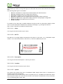
Leveraging Power of Wireless®
Manual
SenzaWMS
E-Senza Technologies GmbH | Bücklestr. 82b | 78467 Konstanz | Germany
T + 49 7531-365 99 10 | F + 49 7531-365 99 29 | [email protected] | www.e-senza.de
Leveraging Power of Wireless®
Safety information
In order to ensure the safe use of the product described, you have to read and understand this
manual. The following notes provide information on how to use this manual.
User group of this manual
The use of products described in this manual is oriented exclusively to
– qualified electricians or persons instructed by them, who are familiar with applicable
standards and other regulations regarding electrical engineering and, in particular, the
relevant safety concepts.
– qualified application programmers and software engineers, who are familiar with the safety
concepts of automation technology and applicable standards.
E-Senza Technologies accepts no liability for erroneous handling or damage to products from ESenza Technologies or third-party products resulting from disregard of information contained in this
manual.
Explanation of symbols used and signal words
The following types of messages provide information about possible property damage and general
information concerning proper operation and ease-of-use.
This is the safety alert symbol. It is used to alert you to potential personal injury
hazards. Obey all safety messages that follow this symbol to avoid possible injury
or death.
The following types of messages provide information about possible property damage and general
information concerning proper operation and ease-of-use.
This symbol and the accompanying text alerts the reader to a situation which may
cause damage or malfunction to the device, either hardware or software, or
surrounding property.
This symbol and the accompanying text provides additional information to the
reader. It is also used as a reference to other sources of information (manuals,
data sheets) on the subject matter, product, etc.
Version V3.1.0.
Leveraging Power of Wireless®
Content
1
SenzaNET ..........................................................................................................1
1.1
Communication in SenzaNET ...........................................................................1
1.2
Network Elements ........................................................................................2
1.2.1
SenzaBlock .............................................................................................2
1.2.2
Gateway ................................................................................................2
1.2.3
SenzaWMS ..............................................................................................2
2 Installation Guide ................................................................................................3
2.1
Automatic Software Installation .......................................................................3
2.2
Manual Software Installation ...........................................................................4
2.2.1
Existing PostgreSQL Installation ....................................................................4
2.2.2
Existing Apache Tomcat Installation...............................................................5
2.3
Starting the SenzaWMS Portal..........................................................................6
3 User Manual .......................................................................................................7
3.1
How to Setup the Gateway .............................................................................7
3.1.1
Default Network Settings ............................................................................7
3.2
How to Setup the Network..............................................................................8
3.2.1
The SenzaWMS Portal.................................................................................8
3.2.1.1
Upper Task Bar..................................................................................8
3.2.1.1.1 Button 1: Close Active Tab ..............................................................9
3.2.1.1.2 Button 2: Refresh Tab ....................................................................9
3.2.1.1.3 Button 3: Network Settings ..............................................................9
3.2.1.1.4 Button 4: Gateway Status .............................................................. 13
3.2.1.1.5 Button 5: Info Button ................................................................... 13
3.2.1.1.6 Button 6: Language Selector........................................................... 13
3.2.1.1.7 Button 7: Network Selector ............................................................ 14
3.2.1.2
Left Menu Bar ................................................................................. 15
3.2.2
Network Menu ....................................................................................... 16
3.2.2.1
Network Status................................................................................ 16
3.2.2.1.1 Edit Node Configuration ................................................................ 17
3.2.2.1.2 Block Basic Parameters ................................................................. 17
3.2.2.1.3 SenzaBlock Interfaces................................................................... 19
3.2.2.2
SenzaBlock Default Parameters............................................................ 22
3.2.2.2.1 Delete SenzaBlocks ...................................................................... 22
3.2.2.3
Buffering in SenzaBlock ..................................................................... 22
3.2.2.4
SenzaHubs ..................................................................................... 23
3.2.2.5
Show Data...................................................................................... 23
3.2.2.6
Authentication ................................................................................ 24
3.2.2.7
Add New Node ................................................................................ 25
3.2.2.8
Export data .................................................................................... 26
3.2.3
Diagrams Menu ...................................................................................... 26
3.2.3.1
Submenu: Graph .............................................................................. 27
3.2.3.2
Lifestats ........................................................................................ 28
3.2.4
Scheduler Menu...................................................................................... 29
3.2.4.1
Task list ........................................................................................ 29
3.2.4.2
Add Task ....................................................................................... 30
3.2.5
Routing Menu ........................................................................................ 31
3.2.5.1
Routing Table ................................................................................. 31
3.2.5.2
Routing Graph................................................................................. 31
3.2.6
Device Types Menu.................................................................................. 32
3.2.6.1
Device Types .................................................................................. 32
3.2.6.2
Configure Device Types ..................................................................... 32
3.2.6.3
Add Device Type .............................................................................. 33
3.2.6.4
Digital Input ................................................................................... 33
3.2.6.5
Pulse ............................................................................................ 34
3.2.6.6
Digital Output ................................................................................. 35
Leveraging Power of Wireless®
3.2.6.7
Analog Output................................................................................. 35
3.2.7
Reports Menu ........................................................................................ 36
3.2.7.1
Alarm List ...................................................................................... 36
3.2.8
Network Manager Menu ............................................................................ 37
3.2.8.1
Default Network .............................................................................. 37
3.2.8.2
Add New Network ............................................................................ 37
4 Integrating SenzaNET into your infrastructure............................................................ 39
4.1
SenzaWMS System Architecture...................................................................... 39
4.2
SenzaWMS Lite .......................................................................................... 40
5 The TCP/IP Interface .......................................................................................... 41
5.1
TCP/IP Settings ......................................................................................... 41
5.2
Usage ..................................................................................................... 41
5.2.1
Login................................................................................................... 42
5.2.2
Network selection................................................................................... 43
5.2.3
List Networks ........................................................................................ 43
5.2.4
Changing Password.................................................................................. 43
5.2.5
Closing Connection.................................................................................. 43
6 SenzaNet Service ............................................................................................... 44
6.1
Troubleshooting in SenzaWMS........................................................................ 44
6.2
Technical Support and Training...................................................................... 45
Copying of this document in full or in part, and giving it to others and the use or communication of
the contents there of, are forbidden without express authority. Offenders are liable to the
payment of damages. All rights reserved for E-Senza Technologies GmbH, Konstanz, Germany in the
event of the grant of a patent or the registration of a utility model or design. (DIN 34-1E)
Leveraging Power of Wireless®
1 SenzaNET
E-Senza Technologies has developed the SenzaNET, a unique wireless device networking protocol,
which enables sensors and actuators to communicate through a self-organizing wireless mesh
network while at the same time it minimizes the devices’ power-consumption thus allowing them to
run on batteries for several years.
SenzaWMS is the software suite to manage one or more such networks, to configure and administer
individual devices and also to manage the data collected from sensor devices and data-exchange
with related control- or IT-systems.
This chapter gives a basic overview of SenzaNET, the devices involved, terminology and features.
1.1 Communication in SenzaNET
The gateway is the network master, responsible for all communication to/from the wireless
network.
Hence, all communication to any network node is done through the gateway (SenzaCoordinator or
SenzaGate). This is possible either via SenzaWMS, the SenzaNET programming interface or through
Field-Bus interfaces.
Fig. 1 SenzaNET System Overview
Manual SenzaWMS
1
SenzaNET-Release: V4.0.1
Leveraging Power of Wireless®
1.2 Network Elements
1.2.1 SenzaBlock
SenzaBlock represents the basic component of SenzaNET. SenzaBlock has mesh networking
capabilities and can interface with devices (e.g. sensors, actuators) at the same time.
SenzaBlocks are available from E-Senza Technologies in different variations for a multitude of
applications.
As adapter-devices or built-in modules, they enable all kinds of sensor and actuator devices to be
controlled wirelessly and exchange data through a self-organizing wireless mesh network with ultralow power consumption.
1.2.2 Gateway
SenzaNET supports integration of the Wireless Network with existing systems or products through
the gateway. You always need a network master to communicate to or from the SenzaBlock. It can
be a SenzaCoordinator or a SenzaGate. They not only support Network Layer functionality but also
provide interfacing to upper layers.
The gateways are available for a multitude of industrial interfaces: Ethernet, Serial, Modbus,
Profibus etc.
1.2.3 SenzaWMS
SenzaWMS is the software-suite accompanying SenzaNET. It provides a very friendly user-interface
for a comfortable administration of the wireless network and monitoring of each individual node.
With SenzaWMS, multiple networks can be managed in parallel, networked devices can be reconfigured, alarm messaging and data acquisition are automated. Comprehensive software-APIs and
data-export options allow seamless integration into existing IT-infrastructures.
Manual SenzaWMS
2
SenzaNET-Release: V4.0.1
Leveraging Power of Wireless®
2 Installation Guide
2.1 Automatic Software Installation
The Setup will start automatically when the SenzaWMS installation CD is put into the CD-drive of
your computer.
If your computers’ configuration is not set for „autorun“, activate autostart for your CD-drive or
execute the file WMSPortal_Version.exe located in folder NSIS of the SenzaWMS installation CD.
The installer will check your system for the required software and install the following components,
if there is no other version already installed on your PC:
Java Runtime Enviroment
PostgreSQL
Apache Tomcat
The SenzaWMS Portal (including Handbook and tools)
Acrobat Reader (optional)
Manual SenzaWMS
3
SenzaNET-Release: V4.0.1
Leveraging Power of Wireless®
In case you have an elder SenzaWMS installation, you MUST uninstall it first before continuing with
the new installation.
Please also back up your data also, if you want to keep the records of your sensor data. You can do
this by help of the Data Export feature or by backing up the database.
Now you have to enter the License Key, which you can find on the CD-ROM cover of your software.
In next step you have to enter the folder where you want your software to be installed.
When the installation finishes, you can start the software on your preferred browser.
2.2 Manual Software Installation
If you have already installed Tomcat, PostgreSQL or Java on your machine and you do not wish to
reinstall these applications, you still can use the Installer. It will automatically detect the installed
components, if the version of the third party tools is same. If you want to use another version of
Tomcat or PostgreSQL to work together with SenzaWMS you have to follow up the next steps.
2.2.1 Existing PostgreSQL Installation
In case you already have installed PostgreSQL 8.2, enter a PostgreSQL user and password in the
installer, assigning the corresponding rights to create DB, insert, select and update tables. If you
want to use any other version of PostgreSQL you can import the file db_dump.sql from following
location on the CD:
Manual Installation\postgresql\
Manual SenzaWMS
4
SenzaNET-Release: V4.0.1
Leveraging Power of Wireless®
You also have to modify the login data in file WMSPortal.xml located on your hard disk at the
following location (in case you already have installed the Tomcat & SenzaWMS):
Program Files\Apache Software Foundation\Tomcat 6.0\conf\Catalina\localhost\
Enter your database user, password and database name. Save the file and restart Tomcat.
2.2.2 Existing Apache Tomcat Installation
In case you have already installed Tomcat 6.0, please import the WMSPortal.war file into Tomcat
Manager from the CD location
Manual Installation\Tomcat
If the standard Tomcat service is running, you can achieve this by opening the browser at port 8080
using address http://localhost:8080. Go to Tomcat Manager and load the WMSPortal.war file from
the CD location mentioned above.
If you have already installed Tomcat 6.0, the installer will find it, and deploy the corresponding
files.
Note: Earlier Version
It is important that the version ID of your existing installations correspond to the one mentioned on
the CD Installer. The Installer is installing Tomcat 6.0, but if you have Tomcat 5.0 on your PC, the
installer will install the new version.
Note: Tomcat Port
It is very important that you keep Port 8080, as predefined. Later on you will access the SenzaWMS
Portal from your webbrowser using address http://localhost:8080/WMSPortal/app. If you change
the port address, then you will have to access SenzaWMS through a modified address:
http://localhost:YOURPORT/WMSPortal/app.
Note: Tomcat as Windows Service
Please note down the user and password which you enter for the Tomcat Webserver, if you install it
manually. You can select Install tomcat as service on the advanced installation menu. With this
selection, Tomcat will be started automatically, with each restart of your PC.
Manual SenzaWMS
5
SenzaNET-Release: V4.0.1
Leveraging Power of Wireless®
2.3 Starting the SenzaWMS Portal
The SenzaWMS Portal starts automatically after the installer has finished. You can also start it from
the Windows Start Menu:
Entering URL http://localhost:8080/WMSPortal/app at your web browser starts the application
directly.
Manual SenzaWMS
6
SenzaNET-Release: V4.0.1
Leveraging Power of Wireless®
3 User Manual
3.1 How to Setup the Gateway
After successfully installing SenzaWMS you need to first plug-in your gateway to the PC.
Now go into menu Network Manager/Network List.
Windows will automatically install the USB driver. If not it is also available on your CDROM.
3.1.1 Default Network Settings
Go into the default network, press Edit. Now please choose USB and the Show COM Ports.
Now chose from here the one with the MAC ID of your gateway (the unique MAC ID of gateway is
mentioned on the label of your product), like in the selection below.
In case you have a RS232 gateway the procedure will be similar.
In case you have an Ethernet gateway you will have to enter the Port manually.
Now press OK and confirm the update.
Please press now the Start Button of the network.
Manual SenzaWMS
7
SenzaNET-Release: V4.0.1
Leveraging Power of Wireless®
You will receive a message that the server now started successfully.
The network will now start reading this port. If you chose a wrong COM port no data from the
wireless devices will appear on your GUI. Therefore please carefully select only COM port with MAC
ID of your Coordinator or Gateway.
3.2 How to Setup the Network
Power each individual SenzaBlock, switch them ON
All new SenzaBlocks will be listed in the Authentication menu of SenzaWMS. Allow all
desired SenzaBlocks into the network (see chapter 0, page 24 for details). During
authentication, you will be asked to configure the devices connected to each SenzaBlock.
Make sure the configuration entered in SenzaWMS matches the HW-configuration of your
SenzaBlock as well as the devices connected. Refer to chapter 3.2.2.1.1, page 17 and your
SenzaBlock manual for details.
When all SenzaBlocks are authenticated and configured, switch to the Network Status
menu. You will find all SenzaBlocks listed here and their status displayed.
Now edit the general network settings using the Network settings menu in the upper task
bar of SenzaWMS. See chapter 3.2.1.1, page 9 for details.
Note:
The gateway has to be always powered for an optimal operation of the wireless network. If the
gateway is not in reach or not powered up, SenzaBlocks will get into scan mode and will
consume more energy/battery.
3.2.1 The SenzaWMS Portal
The application has an upper task bar and a menu bar on the left side.
3.2.1.1 Upper Task Bar
Button 1:
Close
Active
Tab
Button 2:
Refresh
Tab
Manual SenzaWMS
Button 3:
Network
Settings
Button 4:
Gateway
Status
8
Button 5:
About
SenzaWMS
Portal
Button 6:
Language Selection
German
English
Button 7:
Network Selector
SenzaNET-Release: V4.0.1
Leveraging Power of Wireless®
3.2.1.1.1 Button 1: Close Active Tab
Closes the tab in the front view.
3.2.1.1.2 Button 2: Refresh Tab
An automatic refresh with a cycle of 10 sec is inbuilt for all the active tabs.
Yet if you wish to refresh faster or manually, then please press this button.
3.2.1.1.3 Button 3: Network Settings
This function allows an advanced user to change the network heartbeat, branch type and the RF
channels used to transmit data within the wireless network.
Entries made here are determining network and device performance to a large extend and should
be applied carefully.
The nodes normally connect ad-hoc to the network and the user does not need to consider much
about the connection in the first step. Yet, if a certain routing configuration or a certain network
size is required, he has to understand the following settings.
Note: Changing Any Network Settings
When changing and confirming with OK any network settings in this dialog, this dialog will become
inactive for the next 5 heartbeat cycles, as those changes take effect only after this interval and it
is no new changes can be done within this time.
Manual SenzaWMS
9
SenzaNET-Release: V4.0.1
Leveraging Power of Wireless®
3.2.1.1.3.1
Heartbeat
By default, the network is periodically put into sleep mode to save energy and it only wakes up
cyclically. This cycle is called heartbeat. When the heartbeat comes, devices wake up and transmit
or communicate to neighbouring nodes. This time nodes are awake is called OnTime and is either 1
or 2 seconds. If you want the nodes to transmit cyclic data more often or less often, you can change
this heartbeat to the desired time in seconds/minutes.
Note: Network Heartbeat Only
It is only possible to setup a cycle for the network and not for individual devices, since most of the
devices are also routing nodes and support routed communication for other nodes as well.
Note: Changing Heartbeat
When heartbeat is changed from a higher value to a lower value, e.g. from 1 minute to 10 seconds,
user must be aware of the network limitations described in the following chapter under Branch. For
a shorter heartbeat, it might be required to change topology of the network. If a shorter heartbeat
setting violates topology-limitations, SenzaNET will automatically trigger a re-formation of the
network. Such re-formation means SenzaBlocks will be unavailable for a short time and might even
drop from the network completely, if no connection to another SenzaBlock complying with the
topology-rules can be established.
Note: Values Allowed
The heartbeat can only be set as a multiple of 10 sec and max 1440 minutes = 1x day.
Note: Optimal Heartbeat Configuration
Choosing the best heartbeat is a matter of trade-off. There are few suggestions which are important
to know. When starting up a new network or when connecting new nodes to one network, it is
desirable to set the heartbeat low to 10 or 30 seconds, so the new devices are able to find a new
parent relatively fast. After all the nodes are in the network it is desirable to set the heartbeat to a
higher value, something like 5 or 10 minutes, which would be the minimal cycle when you want your
devices to send the data. Yet this would also be the reaction time to new configurations.
3.2.1.1.3.2
Branch
As the whole wireless communication is slotted, the network topology has to fulfil certain
requirements, which also depend on the heartbeat.
All the wireless devices have a dedicated slot of 100ms to send their own data over several hops to
the gateway. In other slots they support communication of other nodes.
Directly connected nodes are nodes which are connected to one gateway directly on the first level.
These nodes then can form a branch, other nodes connecting to the network can either connect to
them or also directly to the coordinator.
The gateway can support HB/2 - 1 directly connected nodes, where HB is the heartbeat in
seconds. SenzaHubs do not count as directly connected nodes. . SenzaBlocks directly connected
to SenzaHubs are also considered as directly connected nodes.
For a 10 sec heartbeat, up to 10/2-1= 4 nodes can be connected directly, creating up to 4 branches.
See following picture
Manual SenzaWMS
10
SenzaNET-Release: V4.0.1
Leveraging Power of Wireless®
Branch 1
Branch 2
Branch 3
Branch 4
For a 60 sec heartbeat, up to 60/2-1= 29 nodes can be connected directly, creating up to 29
branches.
Each branch can support up to (BT * 10) - 1 nodes, where BT is Branch Type and BT =1 for
standard, and BT = 2 for extended, which means that a standard branch can consist of up to 9
nodes, an extended can have up to 19 nodes.
Please see following screenshots with an extended branch (left) and a standard branch (right), both
having the maximum number of nodes possible:
Note: Depth Level
The SenzaNET network allows a maximal depth level of 3, which means 3 devices can be connected
in a row to the gateway !
Manual SenzaWMS
11
SenzaNET-Release: V4.0.1
Leveraging Power of Wireless®
Note: Power Consumption with Branch Types
The drawback of using Branch Type extended is, that the power consumption of all SenzaBlocks in
the network increases by 70%, as they have to stay awake longer to support the communication of
more nodes in their branch.
Note: Changing Configuration of Branch Types
When you change configuration of branch types from standard to extended, one branch can accept
more nodes and the OnTime for the SenzaBlocks increases to 2 seconds. When you change the
branch type to standard, the branch becomes narrower and if it had more nodes connected to it,
they will disconnect and try to reconnect in another branch. The OnTime decreases to 1 seconds
and the devices consume less energy.
Note: Network Connection Characteristics
When SenzaBlocks are getting connected to the network, they try to spread over several branches
according to the best link quality to their parent nodes. Priority is given to connect directly to the
gateway.
Manual SenzaWMS
12
SenzaNET-Release: V4.0.1
Leveraging Power of Wireless®
3.2.1.1.3.3
RF Channel
The network uses 3 RF channels for communication. By default those are 11, 19, 26. This so-called
channel hopping helps the network to avoid interferences with other radio networks. These
channels can be changed by the user, but at least one of the channels must be either 11, 19 or 26,
as newly connecting SenzaBlocks scan the 3 default channels for connection and must be able to
find the network.
User is also allowed to set all 3 hopping-channels to the same channel-number.
When user wants new SenzaBlocks to connect fast, it is desirable to set the channels to default, as
the chance is higher to find a network-connection faster.
Channels are only available from 11 and 26 (IEEE standard for the 2,4
ISM band).
3.2.1.1.4 Button 4: Gateway Status
This button is grey blue, if you have a connection to the gateway.
A red button means that the connection to the gateway is interrupted or the gateway is not
connected to SenzaWMS. Press the button to update connection status with the gateway. For more
information here see Chapter 3.2.8.
3.2.1.1.5 Button 5: Info Button
Information about SenzaWMS, including software version and software license key.
3.2.1.1.6 Button 6: Language Selector
Using Button 6, you can choose the language for SenzaWMS. You can select between German and
English.
This change is only active if you will restart the Tomcat application on the server. See Chapter 6.1.
Manual SenzaWMS
13
SenzaNET-Release: V4.0.1
Leveraging Power of Wireless®
3.2.1.1.7 Button 7: Network Selector
Here you can switch between SenzaNET networks if you operate multiple networks. All actions on
the left menu will be associated to the currently selected network. The tabs are associated to the
network ID, which is coming with the # symbol.
In the following examples you will see that Network Status Tab belongs to Network #1, but the
Routing Graph Tab belongs to Network #26.
Manual SenzaWMS
14
SenzaNET-Release: V4.0.1
Leveraging Power of Wireless®
3.2.1.2 Left Menu Bar
The menu bar on the left consists of two levels of submenus.
Menu Items available in SenzaWMS:
„Network“
„Status“
„Show Data“
“Authentication”
“Add New Node”
“Export Data”
“Diagrams”
“Graph”
“Livestats”
“Scheduler”
“Task List”
“Add Task”
“Routing”
“Routing Table”
“Routing Graph”
“Devices Types”
“Device Types”
“Add Device Type”
“Reports”
“Alarm List”
“Network Manager”
“Network List”
“Add Network”
The second-level menu items become visible when clicking the related first-level menu item.
Manual SenzaWMS
15
SenzaNET-Release: V4.0.1
Leveraging Power of Wireless®
3.2.2 Network Menu
3.2.2.1 Network Status
The network status shows all SenzaBlocks authenticated within the network and their current
status. It also serves as a menu to access all settings of the SenzaBlocks by clicking the respective
Edit Icon (see chapter 3.2.2.1.1) and removing SenzaBlocks from the network (see chapter
3.2.2.2.1).
Status is a column with red or green indicators. Cyclically the SenzaBlocks have to send a
health message. A red element means that the health message of a SenzaBlock was not
received after a timeout of 5 heartbeats.
The Last Message column shows the last time any message from that SenzaBlock was
received.
Link indicates signal strength of the RF-connection of the respective SenzaBlock to it’s
parent node.
The Energy column shows the status of the SenzaBlock’s battery or an adapter if the user
chooses Power External. A power cord symbol is shown here, if the SenzaBlock was
configured for external power supply (see chapter 3.2.2.1.1).
If a SenzaBlock’s battery goes low, the battery image will turn red. If the battery status is
not known, a question mark will appear there when no battery information could be
obtained.
Note: Energy remaining
When the battery sign becomes red first time, the remaining energy is roughly 10% of total
battery capacity.
Note: Sensor Data Unreliable for Low Battery
When the battery is going low, please try to immediately exchange it. As the energy is very
low, the SenzaBlock may not have enough power to read the connected sensors and it will
give wrong readings.
Manual SenzaWMS
16
SenzaNET-Release: V4.0.1
Leveraging Power of Wireless®
Upon clicking one of the icons in the Edit column, a new window opens. With the functions
herein you can configure each individual node of the network. For a detailed description on
how to configure single network nodes see page 17.
The Delete buttons, delete individual SenzaBlocks from the network. If the SenzaBlocks
should not connect to your network anymore, you have to deny them in the Authentication
menu of SenzaWMS as well, when they will appear there again.
3.2.2.1.1 Edit Node Configuration
With this dialog you change the configurations of a network node. This menu is used to setup and
re-configure sensors and other devices connected to a SenzaBlock.
3.2.2.1.2 Block Basic Parameters
Block Type
When you add a Node, you have to choose the node type. The node type is mentioned on the label
of your product.
Manual SenzaWMS
17
SenzaNET-Release: V4.0.1
Leveraging Power of Wireless®
If by mistake you enter a wrong node type, the node itself will correct that with the first message
sent.
The following Node-Types are available:
SB110-T: SenzaBlock for temperature measurements with PT100 interface
SB110-AI: SenzaBlock with two analog input interfaces
SB110-AO: SenzaBlock with two analog output interfaces
SB110-IO: SenzaBlock with two digital input and two digital output interfaces
SB130: SenzaBlock with 4 input and 2 output interfaces, analog/digital configurable
SB140: SenzaBlock with RS232 serial-IO interface
SH140: SenzaHub
For details of the node types, available hardware-variants as well as specification details, please
refer to the documentation available from E-Senza Technologies, e.g. through the Internet:
http://www.e-senza.de/en/products/senzanet.html
3.2.2.1.2.1
Name
You can give the node a name of your choice.
3.2.2.1.2.2
MAC ID
The MAC-ID is a 16-digit number mentioned on the label of your node. It is a worldwide unique
number. As it is the identification of the device, it cannot be updated by the user.
3.2.2.1.2.3
Description
You can give the node a description / name of your choice.
3.2.2.1.2.4
Location
You can give the node a location of your choice.
3.2.2.1.2.5
Upload
The upload cycle defines how often a SenzaBlock should sample sensor data. It is defined as a
multiple of the network heartbeat.
If the heartbeat is 10 seconds and you enter an upload cycle of 2, SenzaBlock will sample the sensor
data every 20 seconds, but it still will be involved in the network communication every 10 seconds,
e.g. for forwarding other nodes’ data.
Manual SenzaWMS
18
SenzaNET-Release: V4.0.1
Leveraging Power of Wireless®
If you want to have data every heartbeat, set this parameter to value 1. Default value for upload is
2.
3.2.2.1.2.6
Power
You can choose either Battery or External as power-options. This setting must be made in
accordance to the power-supply option physically present at the respective node.
If you choose external power supply and you use battery, there will be no notice when the battery
goes low.
Default setting is Battery.
3.2.2.1.2.7
Sleep Mode
On or Off
When you power a node with external power supply you don’t need the device to go in sleep mode.
It will connect faster and react faster to the messages from neighbouring nodes.
Another advantage of SleepMode=off is in case of pre-defined setpoints: The device will
continuously sample the sensors and won’t miss setpoint-violations.
In case of SleepMode=on, the device will only be able to sample at heartbeat and it will miss
setpoint-violations occurring during it’s sleep cycle.
If the node is directly connected to the gateway or a SenzaHub, it will immediately transmit any
setpoint-violations, otherwise it will transmit at heartbeat.
Default setting is Sleepmode = on, to save battery life.
3.2.2.1.2.8
Leaf
You can choose either Leaf or Routing as options.
Leaf means this node will not allow another node to connect to it for routing of data packets. It has
a very short OnTime cycle to reduce power-consumption as much as possible. It is directly
connected to the gateway or the hubs.
Routing means this node will allow any other node to connect to it as long as network size
restrictions are met, see Branches in chapter 3.2.1.1.3.2.
A routing node allows maximum flexibility for building up a true mesh network with redundant paths
and reliable data transmission.
Default setting is Routing, to allow setting up a true mesh network.
3.2.2.1.3 SenzaBlock Interfaces
Within the Edit node window, the tabs Channel 1, 2, … allow you to specify devices connected to a
SenzaBlock.
Manual SenzaWMS
19
SenzaNET-Release: V4.0.1
Leveraging Power of Wireless®
Depending on the SenzaBlock model in use, up to 4 sensors or devices can be connected to it.
Unused SenzaBlock-interfaces should be set to disabled.
Restrictions on setting SenzaBlock interfaces:
-
When the internal temperature sensor is used, all other interfaces will be disabled
0-10V input/output as well as 0-20 / 4-20 mA output interfaces are available with
external power supply only
Manual SenzaWMS
20
SenzaNET-Release: V4.0.1
Leveraging Power of Wireless®
-
When a SenzaBlock supports multiple devices and interface-types, restrictions may
apply as to how many devices with different interface-type can be combined.
Refer to your SenzaBlock manual for details.
3.2.2.1.3.1
Sensor Type
For the on-board temperature sensor, please select Thermo-(C), -(K) or –(F) depending on
temperature units used.
For
connecting
external sensors/devices you have multiple choices depending on the type of SenzaBlock. Please
refer to page 18 for types of SenzaBlocks available.
You can also define your own devices in SenzaNET, which simplifies setup and management, if
multiple sensors/devices of same type are used. Setup of device types if done through the Device
Types Menu, see chapter 0.
Important:
Please note that if you change the sensor type, all the history data of that sensor
will be deleted!
3.2.2.1.3.2
Sp High
Setpoint High. This parameter allows you to set the upper limit of an alarm setpoint on the sensor
selected. A message will appear in the alarm table if this setpoint has been violated. Message will
be thrown only once whenever the limit is crossed.
3.2.2.1.3.3
Sp Low
Setpoint Low. This parameter allows you to set the lower limit of an alarm setpoint on the sensor
selected. A message will appear in the alarm table if this setpoint has been reached. Message will
be thrown only once whenever the limit is crossed.
3.2.2.1.3.4
Init
Init is the offset or zero-point value of the sensor/device connected. It will be used as an offset for
the measured values.
Also this initial value is taken as starting number when digital impulses, e.g. from a metering
device, are to be counted. When SenzaBlock is re-booted, it will be set to this initial value.
This offset can also have a negative value.
3.2.2.1.3.5
Scale
The Scale value is a multiplication factor by which the sampled sensor values will be multiplied
before being displayed and stored in SenzaWMS’s database. Default value is 1.
Important:
The scale factor will be applied to the initial value before the evaluation for
Setpoint-violation will be made !
Manual SenzaWMS
21
SenzaNET-Release: V4.0.1
Leveraging Power of Wireless®
3.2.2.1.3.6
Unit
This is the unit denomination which will be stored and displayd in SenzaWMS. This entry has no
influence on the value displayed.
The Formula used by SenzaWMS to calculate the data value is DatVal = RawVal*Scale + Init
3.2.2.2 SenzaBlock Default Parameters
Default factory settings for SB110-X and SB130 are:
Internal Temperature Readings (DS75)
Upload Cycle = 2
No Setpoints active
Routing Block = ON
Sleep Mode = ON
Blacklist for denied networks = Empty
Buffered Data will be deleted
Pulse = 0
These settings are active unless changed over AT Commands or over SenzaWMS for the lifetime of
the SenzaBlock. Even if the block will be restarted, these settings or the overwritten settings will be
active.
One way to reset the device to the factory settings is by pressing the hardware reset button for it.
Please check here the individual manual of the respective SenzaBlock.
3.2.2.2.1 Delete SenzaBlocks
To delete SenzaBlocks from the network you have to press the bin icon and confirm.
The SenzaBlock’s authentication will be cancelled.
Re-Authenticating a SenzaBlock is done through the Authentication (see chapter 0) or
the Add menu (see chapter 0).
3.2.2.3 Buffering in SenzaBlock
SenzaBlock is not only transmitting sensor data reliably but it is also buffering data messages for the
time it has no connection to its parent. Data is buffered with the real time timestamp until the
buffer is full.
The only situation in which the SenzaBlock is not buffering data messages is when it is rescanning
for its parent, as the connection broke for some time. The rescan mode doesn’t allow it to buffer
messages.
The operator should avoid situations in which SenzaBlock connection may get disturbed for a longer
period of time, if it doesn’t want that the data gets lost.
He can help the network by adding SenzaHubs to it, which have more storing capacity.
Manual SenzaWMS
22
SenzaNET-Release: V4.0.1
Leveraging Power of Wireless®
3.2.2.4 SenzaHubs
SenzaHubs SH140 are network devices which help improve the network performance.
The advantage of using SenzaHubs are:
extend network reach with 3 extra levels
support and reproduce activity of the network gateway
store data
continuous power guarantee a good data sink
position can be chosen free, at a good antenna reach position and not dependent of sensor
or device placement
SenzaHubs also connect to the network with authentication and can be deleted, like any other
node.
They cannot be set to operate on battery or in sleep mode.
3.2.2.5 Show Data
The data display is very similar to the network status with the difference that here the health cycle
of the network is not monitored. Within this section you can monitor the last values sent by a single
SenzaBlock.
Manual SenzaWMS
23
SenzaNET-Release: V4.0.1
Leveraging Power of Wireless®
3.2.2.6 Authentication
When you turn on a SenzaBlock, it will first try to join the network. If the SenzaBlock has not been
authenticated by the network before, it will be listed in this Tab. You can choose to allow or deny
this SenzaBlock access to your network. If you allow this SenzaBlock, the Add SenzaBlock dialog (see
chapter 0) will open with default settings. If you deny a SenzaBlock, it is not allowed to
communicate with anybody in the network. Even if you restart this SenzaBlock it will not connect to
this network anymore.
Important: The only way to enable SenzaBlock joining a network it has been denied from
before is to re-flash it’s memory. There is a specific button for this at SenzaBlock, but
this will erase all configuration information as well. Check SenzaBlock manual for
details.
Manual SenzaWMS
24
SenzaNET-Release: V4.0.1
Leveraging Power of Wireless®
3.2.2.7 Add New Node
This function allows you to add new nodes, e.g. SenzaBlocks, to the network. You will be prompted
to add the MAC-ID of the node and choose the type of node. When you manually add a node to the
network, it is automatically authenticated as well.
a) MAC ID
Is a hexadecimal number mentioned on the label of your node and is a worldwide unique number.
b) Node type
When you add a node, you have to choose the node Type. Node type is mentioned on the label of
your product. If by mistake you enter a wrong node type, the node itself will correct it with the first
message sent.
Manual SenzaWMS
25
SenzaNET-Release: V4.0.1
Leveraging Power of Wireless®
3.2.2.8 Export data
With this dialog, a start and end time interval can be selected for which data of all channels from a
single SenzaBlock will be exported in .csv-format. We recommend to first save the exported file on
your PC and then to re-open it with Microsoft Excel or a compatible tool.
Important: Depending on settings of this tool, data may not be opened properly causing
your data to be displayed wrongly. To check if the data is correct, we recommend
opening the file in a text editor.
3.2.3 Diagrams Menu
The Diagrams menu has two sub-menu items, which are will be shown when Diagrams in the left
menu bar is clicked.
Manual SenzaWMS
26
SenzaNET-Release: V4.0.1
Leveraging Power of Wireless®
3.2.3.1 Submenu: Graph
Within the Graph sub-menu, you can generate a chart displaying values from a specific time
interval.
The user can select simultaneous charts for more then one SenzaBlock, if they are all of the same
sensor type. In this case values from different SenzaBlocks can be compared with each other. Also
same channel type from one SenzaBlock can be compared with each other.
When you have selected the SenzaBlocks for your graph, press OK and a new window appears,
showing you the graph with the information of SenzaBlocks and devices selected:
Manual SenzaWMS
27
SenzaNET-Release: V4.0.1
Leveraging Power of Wireless®
3.2.3.2 Lifestats
The Life Stats is a live diagram of the most recent values from one or more SenzaBlocks of your
choice. Limit” defines the number of history values displayed, this number is limited to 50 to ensure
fast update of the diagram when new values come in from the SenzaBlocks.
Press OK and a new tab is added to the SenzaWMS main window showing the diagram.
Manual SenzaWMS
28
SenzaNET-Release: V4.0.1
Leveraging Power of Wireless®
3.2.4 Scheduler Menu
The scheduler menu is to manage pre-defined tasks SenzaWMS executes automatically.
3.2.4.1 Task list
Task list menu shows all tasks currently defined.
The following tasks are pre-defined:
1. Export All
Manual SenzaWMS
29
SenzaNET-Release: V4.0.1
Leveraging Power of Wireless®
With this task all SenzaBlock data is daily exported into a defined directory on the server.
This directory is the installation directory of the SenzaWMS and has following path if installation was
done in Program Files.
C:\Program Files\WMSPortal\autoexport.
2. Time Synchronization.
With this task your system will be time synchronized once a day with the gateway. This task has to
be active in case clock drifts or changes.
3.2.4.2 Add Task
With this menu you can choose and configure your own tasks within the newly opening window Add
new Job.
Manual SenzaWMS
30
SenzaNET-Release: V4.0.1
Leveraging Power of Wireless®
3.2.5 Routing Menu
3.2.5.1 Routing Table
In this table all parent-child relations in the network are listed showing parent and child node as
well as last time the relation link was transmit by the child node.
3.2.5.2 Routing Graph
This graph shows the network routes. Since SenzaNET configures itself dynamically, the routing
graph can change over time, when connections between nodes are being changed. The SenzaNET
network allows a maximal depth level of 3 !
Manual SenzaWMS
31
SenzaNET-Release: V4.0.1
Leveraging Power of Wireless®
3.2.6 Device Types Menu
3.2.6.1 Device Types
Menu Device Types shows a list of predefined or user configurable devices. These device types are
based on all possible interfaces in all different SenzaBlocks: Analog and digital input and output,
PT100, internal temp sensor etc.
Each device type relates to an interface (column Interface), which refers to the electrical
connection of SenzaBlock.
The Device Type defines the relation between the electrical signal at the SenzaBlocks interface and
the values shown in SenzaWMS and it’s database.
3.2.6.2 Configure Device Types
Example 1:
For a pressure sensor with 0-10V analog output, device type “Pressure sensor XYZ” defines that 0 V
corresponds to a pressure of 0 bar, 10V correspond to 100 bar. Values between 0 and 10 V will be
interpolated linearly.
Example 2:
For an electricity meter, device type “Landis & Gyr no. 502” defines that each pulse counted means
electrical energy of 2 Wh has been consumed.
Manual SenzaWMS
32
SenzaNET-Release: V4.0.1
Leveraging Power of Wireless®
Example 3:
A valve is be controlled through SenzaBlock’s 4-20 mA output interface. The opening cross-section
of the valve is related to the electric current of the 4-20 mA current loop: 4 mA means valve closed,
cross-section 0 mm2, 20 mA relates to 100 mm2. Device Type “Valve ABC” is defined accordingly.
When a SenzaBlocks interface is assigned that device type, SenzaBlock would drive a current of 12
mA through the current loop when receiving 50 mm2 as input value, thus opening the valve to that
cross-section.
You can add, change, delete your own devices to/from the list, see next chapter.
3.2.6.3 Add Device Type
Choose this menu to define your own device in SenzaNET.
Parameters are identical to the ones used for setting up SenzaBlock, see page 19.
3.2.6.4 Digital Input
When Digital Input signals are generated from SB110-IO or SB130 the message will be displayed in
the Alarm List of the Reports Menu.
Also the data comes as 1 for contact closed and 0 for contact open. So you can see also the graph of
the contacts generated on the timeline. See following screenshots.
Manual SenzaWMS
33
SenzaNET-Release: V4.0.1
Leveraging Power of Wireless®
3.2.6.5 Pulse
Pulses come as incremented data over the timeline as in following screen.
Over the SenzaWMS dialog you can set an init value (for example current value on the meter) and a
scale to calibrate your data. This is the software calibration possibility.
In case the respective SenzaBlock is restarted, it will count with the last saved value. If this is not
desired, there are two possibilities to reset the initial value on the SenzaBlock:
- You can press the hardware reset button on your SenzaBlock. This resets the value to 0.
- An easier method is to send a command to the SenzaBlock itself by the Set Value To
Button on the Dialog itself. Here you can not only set 0 but any desired initial value.
Manual SenzaWMS
34
SenzaNET-Release: V4.0.1
Leveraging Power of Wireless®
3.2.6.6 Digital Output
Output signal is send over the SenzaWMS through dialogs below. The channel needs first to be
preconfigured. After the channel is configured the output can be set to On or Off.
Important: Depending on the heartbeat, the output may not be generated at the same
time the user sets the output, as the message has to be received by the SenzaBlock
while it is not in sleep mode. If heartbeat is very high, it can reach the SenzaBlock at
max time of heartbeat. If user wants to have an immediate message being transmitted
to the device, one option is to set up the device as a leaf and without sleep mode on.
3.2.6.7 Analog Output
Output signal is send over the SenzaWMS through dialogs below. The channel needs first to be
preconfigured. After the channel is configured the output can be set to the desired value.
The user has option to choose between:
Manual SenzaWMS
35
SenzaNET-Release: V4.0.1
Leveraging Power of Wireless®
AO
AO
AO
AO
4-20mA
0-20mA
0-2V
0-10V
Important: Depending on the heartbeat, the output may not be generated at the same
time the user sets the output, as the message has to be received by the SenzaBlock
while it is not in sleep mode. If heartbeat is very high, it can reach the SenzaBlock at
max time of heartbeat. If user wants to have an immediate message being transmitted
to the device, one option is to set up the device as a leaf and without sleep mode on.
3.2.7 Reports Menu
3.2.7.1 Alarm List
The Alarm list shows the history of all events where pre-defined Setpoints where violated, or when
Digital Input signals where generated.
See Chapter 3.2.2.1.3.2 on how to define Setpoints and chapter 3.2.6.
The Clear List Button erases all entries.
Manual SenzaWMS
36
SenzaNET-Release: V4.0.1
Leveraging Power of Wireless®
3.2.8 Network Manager Menu
3.2.8.1 Default Network
Please check the description from Chapter 3.1.1.
3.2.8.2 Add New Network
When you want to add new networks to the portal, you have to purchase extra network licenses
from E-Senza Technologies. For that you will have to give the license key of your current SenzaWMS
installation. This key can be also found in the screen at the Info Button, see Chapter 3.2.1.1.
Then you can fill up the data like in following screenshot: the MAC ID of your gateway, network
type, port and license.
Manual SenzaWMS
37
SenzaNET-Release: V4.0.1
Leveraging Power of Wireless®
When the data has been filled, press ok and then press the Start network button.
Now your new network will appear in the ComboBox in the Upper Task Bar.
Manual SenzaWMS
38
SenzaNET-Release: V4.0.1
Leveraging Power of Wireless®
4 Integrating SenzaNET into your infrastructure
4.1 SenzaWMS System Architecture
SenzaWMS as a system was developed with a focus on integration into existing systeminfrastructures. SenzaNET and SenzaWMS feature a wide range of interfaces, which results in various
options to integrate them into your infrastructure:
•
Standalone-system: The SenzaWMS application is installed on a standard PC. SenzaNET is
accessed through a USB-, RS232- or Ethernet-gateway. This is the easiest jump-start with
SenzaNET. All network-, device- and data-management is done using the SenzaWMS Portal
through your Webbrowser.
•
Server-installation: The SenzaWMS application is installed on a server. SenzaNET is
accessed through an Ethernet/Internet connection to this server. All network-, device- and
data-management is done using the SenzaWMS Portal through the Webbrowser from any
remote PC with an Ethernet/Internet-connection to the server. The SenzaWMS-server, the
individual SenzaNETs and the users accessing SenzaWMS can be located almost anywhere.
All they need is an Internet-connection.
•
Database-interfacing: SenzaWMS is run standalone. Network- and device-management is
done through SenzaWMS. Data collected by SenzaNET is available in SenzaWMS, but
additionally, the ODBC-interface can be used to read data into another data-processing
software. This could be a central database or an Excel-like application. This way, existing
data-management solutions are re-used. Note: No manual/automatic data-export from
SenzaWMS is required.
•
SOAP Interface: SenzaWMS is run server-based and starts its SOAP Server Engine. It will be
operated as part of a larger control-system and exchange data and commands with a
network master, such as an OPC-server. SOAP is a common message-format applied in this
case. The type and format of messages exchanged depend on the application.
•
Field-Bus Connection: SenzaWMS is run either standalone from PC or server-based.
SenzaWMS will be used for network and device management. Process data will be
exchanged directly between SenzaGate and the process control system through the FieldBus connection (ProfiBus, Modbus etc.). SenzaGate will generally operate two interfaces: an
USB or Ethernet interface for network/device management purposes and the Field-Bus
interface to exchange process data with the process control system. Exchanging
network/device information through Field-Bus is possible as well, but will usually require
customization for optimum Field-Bus performance.
•
SenzaNET programming: SenzaNET can be operated without SenzaWMS as well. All
functionality of SenzaNET is available through the SenzaNET programming interface. This
interface uses AT-commands exchanged over the gateway interfaces.
•
TCP/IP interface is available as well, which uses the same AT-commands, but it requires a
SenzaWMS installation. SenzaWMS is run either standalone from PC or server-based.
SenzaWMS will be used for network and device management. Using the TCP/IP interface,
one connects to the PC/server where the SenzaWMS installation is running. All dataexchange with the devices is then tunneled through TCP/IP.
Manual SenzaWMS
39
SenzaNET-Release: V4.0.1
Leveraging Power of Wireless®
4.2 SenzaWMS Lite
Customers who purchased evaluation kits will receive the SenzaWMS Enterprise free of cost for 3
months.
After 3 months just the basic functionality of the user interface is available:
- Show Data
- Network Status
- Export Data
- Edit Block
If you wish to have the complete functionality, please request an offer from our sales team at
[email protected].
Manual SenzaWMS
40
SenzaNET-Release: V4.0.1
Leveraging Power of Wireless®
5 The TCP/IP Interface
This chapter describes the Telnet interface of SenzaWMS. This interface enables the parallel access
to the AT Commands of the gateway via Telnet and to the SenzaWMS.
The base application is a multi connection telnet application. Each connection is working as a pipe
to the gateway after successful authentication.
5.1 TCP/IP Settings
The Telnet interface is running by default on TCP Port 7701.
The Telnet interface is not only a pipe to the AT interface. It has also features for security and it is
more user friendly.
5.2 Usage
To use the telnet interface, you need a telnet application. You can use telnet from Windows, or a
more comfortable client like Advanced Serial Port Terminal1. First, open a connection to the PC
where the SenzaWMS is running at port 7701.
After this dialog, go to preferences (Ctrl+P) and enable Mixmode and set #0D after send.
1
http://www.eltima.com/products/serial-port-terminal/
Manual SenzaWMS
41
SenzaNET-Release: V4.0.1
Leveraging Power of Wireless®
Confirm these settings, then press open in the toolbar to establish the connection
5.2.1
Login
After the connection is established, you will get the following welcome message.
Manual SenzaWMS
42
SenzaNET-Release: V4.0.1
Leveraging Power of Wireless®
Now you have to enter the password for the telnet interface. By default it is “WMSTelnet”.
When you are successfully logged in the following commands are available:
• MAC
• list
• passwd
• exit
5.2.2
Network selection
After logging in, you have to select the network to which the commands should be sent. This is
important because SenzaWMS is supporting more than one network.
Until you select a network, no communication with the gateway will be possible. Only commands for
the telnet interface are available.
By typing the MAC address of the gateway, you can switch between the networks. But you can only
handle one at the same time per connection. If you want to control several networks at the same
time, you have to establish several telnet connections.
To switch to the network with the gateway with the Mac address 001AEE000000001, you have to
enter
MAC 001AEE000000001
in your telnet application. Now you are connected to this network. You will receive all incoming
data in the terminal, and everything that is typed in, is directly sent to the gateway except the
interface commands.
5.2.3
List Networks
If you don’t know the MAC addresses of the current connected networks, you can list them by typing
List
in your telnet application.
5.2.4 Changing Password
You can change the password for the telnet interface by using the linux-like command passwd.
passwd
Enter NEW password:test
Re-Enter NEW Password:test
The password will be stored encrypted in the database.
5.2.5 Closing Connection
You can leave the telnet interface by typing
Exit
This will safely shut down all connections. This will not have any effect on SenzaNET or SenzaWMS.
Note Network Manager
It is not advisable to use the telnet interface parallel to the SenzaWMS if you want to make network
configuration changes, as the SenzaWMS is the only certified network manager for the SenzaNet.
This interface is meant mainly to automatically push the sensor data into your own system, whereby
a parser has to be written over the AT commands.
Manual SenzaWMS
43
SenzaNET-Release: V4.0.1
Leveraging Power of Wireless®
6 SenzaNet Service
6.1 Troubleshooting in SenzaWMS
1. Block sends data slower than they send health
Check the upload cycle in Block Edit, that is by default set to 2.
2. The blocks do not appear in Authentication or in Show Data
Check if the blocks have not been denied for that network. A hardware reset button is
available to go back to the default settings. See Block manual for that.
The COM Port/Ethernet settings of the gateway are wrong. Confirm that the MACID is
chosen once with the COM Port in Network List.
3. Gateway status-icon remains red
Check settings in network manager
Network type correct? TCP/IP; USB; etc.
Port correct?
MAC ID correct?!
Network Started?
Check Hardware Troubleshooting Guide (gateway not powered)
4. I changed the language but nothing happened.
You need to restart Tomcat
o Start application from Windows Start All Programs -> Apache Tomcat Monitor Tomcat
o Apache Tomcat Symbol near the clock, right mouse click on Stop
o After successful stop repeat the process START
5. SenzaWMS is running, Gateway status-ICON is blue, blocks are started, but they are not visible
in the WMS.
Blocks need to be authenticated
WMS-Menu Network Authentication Allow single blocks
In case you have several networks and several gateways (in neighbourhood or on the
SenzaWMS Enterprise), blocks may connect to other networks/gateways. Here their
access must be denied.
Check if you have selected the correct network and the selected the status from that
network only.
6. There are several networks and the user is changing between them, but the Network Status
doesn’t change.
Here you have to open each tab again, i.e. over Status or Show Data, in order to see the
respective networks
The network ID #X shows the ID of the corresponding network
7. The Block was changed under block configuration, but it is not appearing at Show Data
anymore.
The new values come with the new heartbeat and the upload cycle
8. Time and Date do not match
Check system time on the PC where SenzaWMS was installed
If PC with SenzaWMS installation (server) is different than the PC you are
accessing the webserver, it can be that the time of client and time of server
do not match
If the server time is correct, you can resend the correct time from network settings.
This will propagate the correct time into the network
9. Is the window at SenzaWMS automatically updated?
Manual SenzaWMS
44
SenzaNET-Release: V4.0.1
Leveraging Power of Wireless®
The windows are updated every 10 seconds, if you want to have it faster then you can
press the Refresh-Button from SenzaWMS.
10. How to access SenzaWMS from another PC than the one the installation was done?
SenzaWMS can be accessed from any PC in an intranet with the address:
http://SERVER-iP:8080/WMSPortal/app
where ServerIP is the IP address of the PC where SenzaWMS was installed.
In Default Windows Firewall settings you have to set a new rule.
For this please go to Control Panel ->Windows Firewall ->Exceptions -> Port and make
following entry on the SenzaWMS server PC. Press ok. Now you should be able to access
your SenzaWMS portal from any other PC in the intranet.
6.2 Technical Support and Training
Send your technical questions directly to our team of product specialists.
Email: [email protected]
Phone: +49 7531 365 99 – 19
9am – 5pm Central European Time
Trainings are available on a regular basis and can be arranged on request as well.
Visit our website for the latest training schedule:
http://www.e-senza.de/en/sales/training.html
or get in touch with our team in case of questions or specific training needs:
[email protected]
Manual SenzaWMS
45
SenzaNET-Release: V4.0.1