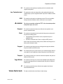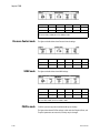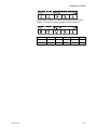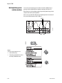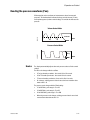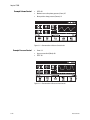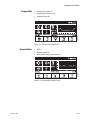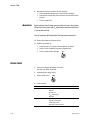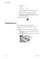
1
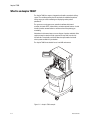
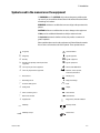
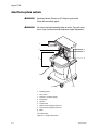
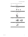
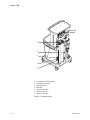
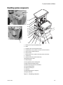
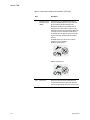
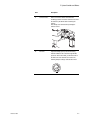
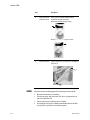
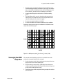
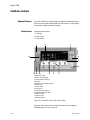
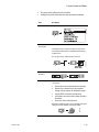
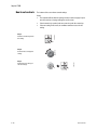
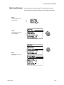
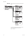
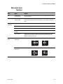
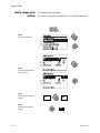
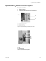
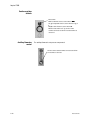
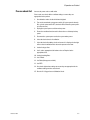
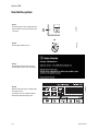
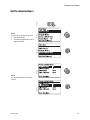
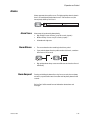
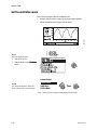
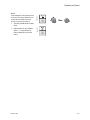
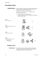
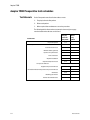
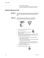
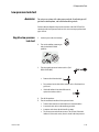
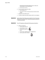
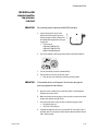
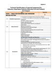
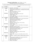
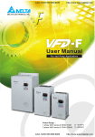
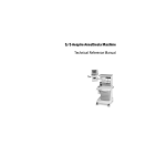
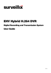
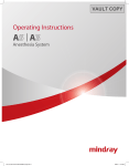
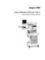
Aespire 7900
User’s Reference Manual—Part 1
System Controls, Operation, Checkout
User Responsibility
This Product will perform in conformity with the description thereof contained
in this User’s Reference manual and accompanying labels and/or inserts,
when assembled, operated, maintained, and repaired in accordance with the
instructions provided. This Product must be checked periodically. A defective
Product should not be used. Parts that are broken, missing, plainly worn,
distorted, or contaminated should be replaced immediately. Should repair
or replacement become necessary, Datex-Ohmeda recommends that a
telephonic or written request for service advice be made to the nearest
Datex-Ohmeda Customer Service Center. This Product or any of its parts
should not be repaired other than in accordance with written instructions
provided by Datex-Ohmeda and by Datex-Ohmeda trained personnel.
The Product must not be altered without the prior written approval of
Datex-Ohmeda. The user of this Product shall have the sole responsibility
for any malfunction which results from improper use, faulty maintenance,
improper repair, damage, or alteration by anyone other than Datex-Ohmeda.
w CAUTION
U.S. Federal law restricts this device to sale by or on the order of
a licensed medical practitioner. Outside the U.S.A., check local
laws for any restriction that may apply.
Datex-Ohmeda products have unit serial numbers with coded logic which
indicates a product group code, the year of manufacture, and a sequential
unit number for identification.
AAA F 12345
This alpha character indicates the year of product
manufacture and when the serial number was
assigned; “D” = 2000, “E” = 2001, “F” = 2002, etc.
“I” and “O” are not used.
S/5 Aespire, Link-25, Disposable Multi Absorber, Reusable Multi
Absorber, SmartVent, Tec 6 Plus, and Tec 7are registered trademarks of
Datex-Ohmeda Inc.
Other brand names or product names used in this manual are trademarks or
registered trademarks of their respective holders.
Table of Contents
1 Introduction
What is an Aespire 7900? . . . . . . . . . . . . . . . . . . . . . . . . . . . . . . . . . . . . . . . 1-2
Symbols used in the manual or on the equipment . . . . . . . . . . . . . . . . . . . . 1-3
2 System Controls and Menus
Anesthesia system controls . . . . . . . . . . . . . . . . . . . . . . . . . . . . . . . . . . . . . . 2-2
Breathing system components . . . . . . . . . . . . . . . . . . . . . . . . . . . . . . . . . . . . 2-5
ACGO . . . . . . . . . . . . . . . . . . . . . . . . . . . . . . . . . . . . . . . . . . . . . . . . . . . . 2-8
Scavenging the ACGO sample flow . . . . . . . . . . . . . . . . . . . . . . . . . . . . 2-9
Scavenging from the external manual breathing circuit . . . . . . . . . . .2-10
Vaporizer controls . . . . . . . . . . . . . . . . . . . . . . . . . . . . . . . . . . . . . . . . . . . . .2-10
Ventilator controls . . . . . . . . . . . . . . . . . . . . . . . . . . . . . . . . . . . . . . . . . . . . .2-12
Optional Features . . . . . . . . . . . . . . . . . . . . . . . . . . . . . . . . . . . . . . . . .2-12
Control panel . . . . . . . . . . . . . . . . . . . . . . . . . . . . . . . . . . . . . . . . . . . . .2-12
How to set controls . . . . . . . . . . . . . . . . . . . . . . . . . . . . . . . . . . . . . . . .2-14
How to use the menu . . . . . . . . . . . . . . . . . . . . . . . . . . . . . . . . . . . . . . .2-15
Menu map . . . . . . . . . . . . . . . . . . . . . . . . . . . . . . . . . . . . . . . . . . . . . . .2-16
More about menu functions . . . . . . . . . . . . . . . . . . . . . . . . . . . . . . . . .2-17
How to change menu settings . . . . . . . . . . . . . . . . . . . . . . . . . . . . . . . .2-18
Optional auxiliary O2 flowmeter and suction regulators . . . . . . . . . . . . . . .2-19
3 Operation and Tutorial
Pre-use check list . . . . . . . . . . . . . . . . . . . . . . . . . . . . . . . . . . . . . . . . . . . 3-3
Turn On the system . . . . . . . . . . . . . . . . . . . . . . . . . . . . . . . . . . . . . . . . . . . . . 3-4
Set the alarm loudness . . . . . . . . . . . . . . . . . . . . . . . . . . . . . . . . . . . . . . . . . . 3-5
Show or hide alarm limits and units . . . . . . . . . . . . . . . . . . . . . . . . . . . . . . . . 3-7
Turn the volume alarms on or off . . . . . . . . . . . . . . . . . . . . . . . . . . . . . . . . . . 3-8
Set alarm limits . . . . . . . . . . . . . . . . . . . . . . . . . . . . . . . . . . . . . . . . . . . . . . . . 3-8
Set an audible alarm for circuit leaks . . . . . . . . . . . . . . . . . . . . . . . . . . . . .3-10
Set Cardiac Bypass . . . . . . . . . . . . . . . . . . . . . . . . . . . . . . . . . . . . . . . . . . . .3-11
1009-0632-000
i
S/5 Aespire
Start mechanical ventilation . . . . . . . . . . . . . . . . . . . . . . . . . . . . . . . . . . . .3-13
Stop mechanical ventilation . . . . . . . . . . . . . . . . . . . . . . . . . . . . . . . . . . . . .3-14
Alarms . . . . . . . . . . . . . . . . . . . . . . . . . . . . . . . . . . . . . . . . . . . . . . . . . . . . . .3-15
Alarm Tones . . . . . . . . . . . . . . . . . . . . . . . . . . . . . . . . . . . . . . . . . . . . . .3-15
Alarm Silence . . . . . . . . . . . . . . . . . . . . . . . . . . . . . . . . . . . . . . . . . . . . .3-15
Alarm Suspend . . . . . . . . . . . . . . . . . . . . . . . . . . . . . . . . . . . . . . . . . . .3-15
Set the ventilation mode . . . . . . . . . . . . . . . . . . . . . . . . . . . . . . . . . . . . . . . .3-16
Set ventilator controls . . . . . . . . . . . . . . . . . . . . . . . . . . . . . . . . . . . . . . . . . .3-18
Optional features . . . . . . . . . . . . . . . . . . . . . . . . . . . . . . . . . . . . . . . . . .3-18
Ventilator controls . . . . . . . . . . . . . . . . . . . . . . . . . . . . . . . . . . . . . . . . .3-18
Volume Control mode . . . . . . . . . . . . . . . . . . . . . . . . . . . . . . . . . . . . . .3-19
Pressure Control mode . . . . . . . . . . . . . . . . . . . . . . . . . . . . . . . . . . . . .3-20
SIMV mode . . . . . . . . . . . . . . . . . . . . . . . . . . . . . . . . . . . . . . . . . . . . . . .3-20
PSVPro mode . . . . . . . . . . . . . . . . . . . . . . . . . . . . . . . . . . . . . . . . . . . . .3-20
Set inspiratory pause (volume modes) . . . . . . . . . . . . . . . . . . . . . . . .3-22
Set SIMV and PSVPro controls . . . . . . . . . . . . . . . . . . . . . . . . . . . . . . . . . . .3-24
Silence alarms . . . . . . . . . . . . . . . . . . . . . . . . . . . . . . . . . . . . . . . . . . . . . . . .3-26
Reading the pressure waveform (Paw) . . . . . . . . . . . . . . . . . . . . . . . . . . . .3-27
Scales . . . . . . . . . . . . . . . . . . . . . . . . . . . . . . . . . . . . . . . . . . . . . . . . . . .3-27
Measure circuit compliance . . . . . . . . . . . . . . . . . . . . . . . . . . . . . . . . . . . . .3-30
Show the service settings . . . . . . . . . . . . . . . . . . . . . . . . . . . . . . . . . . . . . . .3-31
Measure circuit compliance . . . . . . . . . . . . . . . . . . . . . . . . . . . . . . . . . . . . .3-33
4 Preoperative Tests
Aespire 7900 Preoperative tests schedules . . . . . . . . . . . . . . . . . . . . . . . . . 4-2
Test Intervals . . . . . . . . . . . . . . . . . . . . . . . . . . . . . . . . . . . . . . . . . . . . . . 4-2
Test devices . . . . . . . . . . . . . . . . . . . . . . . . . . . . . . . . . . . . . . . . . . . . . . . 4-3
Inspect the System . . . . . . . . . . . . . . . . . . . . . . . . . . . . . . . . . . . . . . . . . . . . . 4-4
Power failure alarm test . . . . . . . . . . . . . . . . . . . . . . . . . . . . . . . . . . . . . . . . . 4-5
Minimize alarms (optional) . . . . . . . . . . . . . . . . . . . . . . . . . . . . . . . . . . . . . . . 4-5
Pipeline and cylinder tests . . . . . . . . . . . . . . . . . . . . . . . . . . . . . . . . . . . . . . . 4-6
Flow control tests . . . . . . . . . . . . . . . . . . . . . . . . . . . . . . . . . . . . . . . . . . . . . . . 4-7
Vaporizer installation . . . . . . . . . . . . . . . . . . . . . . . . . . . . . . . . . . . . . . . . . . . 4-9
Vaporizer back pressure test . . . . . . . . . . . . . . . . . . . . . . . . . . . . . . . . . . . .4-10
Low-pressure leak test . . . . . . . . . . . . . . . . . . . . . . . . . . . . . . . . . . . . . . . . .4-11
Negative low-pressure
leak test . . . . . . . . . . . . . . . . . . . . . . . . . . . . . . . . . . . . . . . . . . . . . . . . .4-11
ii
1009-0632-000
ISO 5358 or BSI standard positive low-pressure
leak test . . . . . . . . . . . . . . . . . . . . . . . . . . . . . . . . . . . . . . . . . . . . . . . . .4-13
Alarm tests . . . . . . . . . . . . . . . . . . . . . . . . . . . . . . . . . . . . . . . . . . . . . . . . . . .4-14
Breathing system tests . . . . . . . . . . . . . . . . . . . . . . . . . . . . . . . . . . . . . . . . .4-16
Monitor and ventilator tests . . . . . . . . . . . . . . . . . . . . . . . . . . . . . . . . . . . . .4-18
Index
Warranty
1009-0632-000
iii
S/5 Aespire
iv
1009-0632-000
1 Introduction
In this section
What is an Aespire 7900? . . . . . . . . . . . . . . . . . . . . . . . . . . . . . . . . . . . . . . . 1-2
Symbols used in the manual or on the equipment . . . . . . . . . . . . . . . . . . . . 1-3
1009-0632-000
1-1
Aespire 7900
What is an Aespire 7900?
The Aespire 7900 is a compact, integrated and intuitive anesthesia delivery
system. The ventilator portion provides mechanical ventilation for patients
during surgery as well as monitoring and displaying various patient
parameters.
The system uses a microprocessor-controlled ventilator with internal
monitors, electronic PEEP, Volume Mode, and other optional features. A serial
interface permits communication to cardiovascular and respiratory gas
monitoring.
Illustrations in this manual may not cover all types of options available. Other
equipment may be attached to the system on the top shelf or on the side
dovetail rails. Consult with your Datex-Ohmeda representative for details
about systems available in your location.
The Aespire 7900 is not suitable for use in an MRI environment.
Figure 1-1 • Aespire 7900 example
1-2
1009-0632-000
1 Introduction
Symbols used in the manual or on the equipment
w WARNINGS and w CAUTIONS tell you about dangerous conditions that
can occur if you do not follow all instructions in this manual. Read and follow
all warnings and cautions.
WARNINGS tell about a condition that can cause injury to the operator or the
patient.
CAUTIONS tell about a condition that can cause damage to the equipment.
A Note provides additional information to clarify a statement in text.
An Important statement is similar to a Note, but provides a comment of
greater emphasis.
Other symbols replace words on the equipment or in Datex-Ohmeda manuals.
No one device or manual uses all of the symbols. These symbols include:
ø On (power)
Í Not autoclavable
O Off (power)
m Type B equipment
o Standby
µ Type BF equipment
q Standby or preparatory state for part of the
H Type CF equipment
equipment
p “ON” only for part of the equipment
w Caution, ISO 7000-0434
œ “OFF” only for part of the equipment
wW Attention, refer to product
† Direct current
N
N
instructions, IEC 601-1.
This way is up.
∏ Alternating current
π Dangerous Voltage
x Protective earth ground
≈
y Earth ground
r Frame or chassis ground
å Alarm silence button
Y Equipotential
t Variability
T
1009-0632-000
Variability in steps
Input
Output
REF Stock Number
SN Serial Number
R
Bag position/ manual ventilation
Read top of float
Vacuum inlet
1-3
Aespire 7900
+
Plus, positive polarity
P
Lamp, lighting, illumination
Cylinder
N
Movement in one direction
Isolation transformer
ˆ
Movement in two directions
Low pressure leak test
Minus, negative polarity
z
Lock
Z
Unlock
134°C
C Autoclavable
u Open drain (remove liquid)
q
t
XXXX
1-4
Suction bottle outlet
O+
2
O2 Flush button
r Mechanical ventilation
U Close drain
Q
Expiratory flow
Alarm silence touch key
Inspiratory flow
Menu touch key
O2 sensor connection
Alarm silence touch key
(Tec 6)
Volume alarms On/Off touch key
End case touch key
Systems with this mark agree with the
European Council Directive (93/42/EEC) for
Medical Devices when they are used as
specified in their Operation and Maintenance
Manuals. The xxxx is the certification number
of the Notified Body used by Datex-Ohmeda’s
Quality Systems.
European Union Representative
1009-0632-000
2 System Controls and Menus
In this section
Anesthesia system controls . . . . . . . . . . . . . . . . . . . . . . . . . . . . . . . . . . . . . . 2-2
Breathing system components . . . . . . . . . . . . . . . . . . . . . . . . . . . . . . . . . . . . 2-5
Vaporizer controls . . . . . . . . . . . . . . . . . . . . . . . . . . . . . . . . . . . . . . . . . . . . .2-10
Ventilator controls . . . . . . . . . . . . . . . . . . . . . . . . . . . . . . . . . . . . . . . . . . . . .2-12
Optional auxiliary O2 flowmeter and suction regulators . . . . . . . . . . . . . . .2-19
1009-0632-000
2-1
Aespire 7900
Anesthesia system controls
wWARNING
Explosion Hazard. Do not use S/5 Aespire systems with
flammable anesthetic agents.
wWARNING
Do not use antistatic breathing tubes or masks. They can cause
burns if you use them near high frequency surgical equipment.
3
2
4
5
1
6
10
9
7, 8
1. Breathing system
2. Flow controls
3. Ventilator / monitoring display
4. Dovetail rails
5. Vaporizer
6. System switch
7. Pipeline pressure gauge(s) (upper row)
8. Cylinder pressure gauge(s) (lower row)
9. Brake
10. O2 flush button
Figure 2-1 • Aespire (front view)
2-2
1009-0632-000
2 System Controls and Menus
Figure 2-1 shows these controls on the front of the S/5 Aespire.
Item
1009-0632-000
Description
2
Flow controls
Turn the control counterclockwise to increase the flow
and clockwise to decrease. The system switch must
be On for gas to flow.
7
System switch
Set the switch to the on (|) position to permit gas flow
and to turn on the system.
9
Brake
Push down to lock. Lift to release.
10
O2 flush button
Push the O2 flush button to supply high flows of O2 to
the breathing system.
2-3
Aespire 7900
1
2
7
6
5
4
3
1.
2.
3.
4.
5.
6.
7.
Circuit Breaker for Electrical Outlet
Electrical Outlet (optional)
Equipotential Stud
Mains Inlet
System Circuit Breaker
Cylinder(s) (optional)
Pipeline Connection(s)
Figure 2-2 • Aespire rear view
2-4
1009-0632-000
2 System Controls and Menus
Breathing system components
19
17
16
15
1
14
13
2
12
11
10
9
18
8
7
6
5
4
3
1. Auxiliary common gas outlet (ACGO) switch
2. ACGO
3. Inspiratory check valve (unidirectional valve)
4. Inspiratory flow sensor / patient connection (circuit connections)
5. Canister (carbon dioxide absorbent)
6. Canister release
7. Expiratory flow sensor / patient connection (circuit connections)
8. Leak test plug
9. Expiratory check valve (unidirectional valve)
10. Breathing system release
11. Manual bag port
12. APL (adjustable pressure-limiting) valve
13. Bag/mechanical ventilation switch
14. Bellows assembly (mechanical ventilation)
15. Pressure gauge (airway)
16. Sample gas return port
17. Serial port
18. Manual Bag (optional; no bag arm)
19. Bag arm (optional)
Figure 2-3 • Breathing system parts
1009-0632-000
2-5
Aespire 7900
Figure 2-3 shows these controls on the front of the S/5 Aespire.
Item
1
Description
Auxiliary Common
Gas Outlet switch
(ACGO)
Sends fresh gas to the ACGO when the switch is
activated. The ACGO may be used to provide fresh
gas to an external manual breathing circuit.
Mechanical ventilation is not available when the
auxiliary outlet is selected and a medium priority
alarm will sound and a message “Aux Gas Outlet On”
is displayed. Pressure and volume monitoring are
not available when the ACGO is selected. Fresh gas
oxygen monitoring is available when the ACGO is
selected.
The ACGO should not be used to drive external
ventilators or for jet ventilation.
Breathing system selected:
Auxiliary outlet selected:
4&7
2-6
Flow sensor
Flow sensors provide volume measurements for
some monitoring functions. All systems have flow
sensors in both positions of the flow sensor module.
1009-0632-000
2 System Controls and Menus
Item
Description
6
Canister release
Push to remove the canister. This allows the
breathing system to vent to the room. Be sure to hold
the canister by the handle before releasing the
canister.
Note: Always do a leak test after operating the
canister release.
12
APL valve
Adjusts breathing system pressure limit during
manual ventilation. The scale shows approximate
pressures. Above 30 cm H2O, you will feel clicks as
the knob turns. Turn clockwise to increase. The
following example setting is at about 20 cm H2O:
MI
N
30
70
20
1009-0632-000
2-7
Aespire 7900
Item
13
Description
Bag / Mechanical
Ventilation switch
Selects between manual ventilation (bag) or
mechanical ventilation (ventilator).
Mechanical ventilation Off (gas to bag):
Mechanical ventilation On (gas to bellows):
17
Bag arm (optional)
Squeeze at (1) to raise or lower the arm. The Bag arm
rotates at (2).
1
2
ACGO
2-8
When you operate a breathing apparatus with fresh gas from the ACGO:
• Mechanical ventilation is not available.
• The pressure gauge, Bag/Vent switch, APL valve, and bag arm are not
part of the external circuit.
• Volume and pressure monitoring are not available.
• O2 monitoring of fresh gas is available automatically when the ACGO is
selected if the system has the O2 monitoring option.
1009-0632-000
2 System Controls and Menus
• Fresh gas oxygen concentration is displayed on the ventilation screen.
Set alarm limits appropriately. Note that fresh gas oxygen concentration
may not reflect FiO2 in rebreathing circuits such as the Mapleson series.
Use an external O2 monitor if using a rebreathing circuit on ACGO.
• A sample of the fresh gas is diverted to the O2 cell in the breathing
system.
• The sample flow to the O2 sensor is dependent on the pressure in the
external circuit. The sample flow reduces the fresh gas flowrate to the
external breathing circuit as shown in the graph.
• Do not use an external ventilator on the ACGO.
• Do not use the ACGO to drive external ventilators or for jet ventilation.
Estimate the mean pressure required for ventilation and determine a mean
sample flow rate from the graph:
3
2
L/min
1
10
20
30
40
50
60
70
80
cm H2 0
Figure 2-4 • Back pressure (cm H20) vs. flow to O2 sensor (L/min)
Scavenging the ACGO
sample flow
If the external manual breathing circuit is to be used with N 2O or volatile
anesthetics, the sample flow should be scavenged.
1. Occlude the patient circuit of the breathing system by using the leak test
plug located to the rear of the expiratory port.
2. Check for clinically correct settings. Set the Bag to Vent switch to the
ventilator mode. Alternatively set the Bag to Vent switch to the bag mode
and set the APL to MIN and attach a bag.
3. The bellows, or bag, will fill slowly with the fresh gas sample flow and then
spill to the AGSS.
1009-0632-000
2-9
Aespire 7900
Scavenging from the
external manual
breathing circuit
If the external manual breathing circuit is to be used with N 2O or volatile
anesthetics, the exhaust should be scavenged.
An auxiliary inlet is available for active AGSS units. It provides a 30 mm male
connection into the auxiliary port under the breathing system.
• The auxiliary inlet is a convenience inlet to the air brake of active AGSS
units. There is a reservoir to capture exhaust flows higher than the extract
flow.
For all AGSS, a separate exhaust hose is necessary from the external manual
circuit to the disposal point.
Vaporizer controls
Refer to the description in this section and the vaporizer operation and
maintenance manual for more detailed information on the vaporizer.
Figure 2-5 shows the vaporizer controls.
1
2
3
4
1.
2.
3.
4.
Lock Lever
Concentration Control and Release
Tec 6 Plus
Tec 7
Figure 2-5 • Vaporizer controls
Item
1
2-10
Description
Lock lever
Turn the lever fully clockwise to lock the vaporizer in
position.
1009-0632-000
2 System Controls and Menus
Item
2
Description
Concentration
Push the release and turn the concentration control
control and release to set the agent concentration. The Tec 6 Plus
concentration control does not turn as long as the
warm-up indicator is on.
Åben
1009-0632-000
2-11
Aespire 7900
Ventilator controls
Optional Features
Control panel
The Aespire 7900 can be equipped with several optional ventilation functions.
References made in this manual to SIMV and PSVPro modes, are only applicable to systems equipped with these functions.
Ventilator controls include:
• Touch keys
• Menu screens
• A control knob
2
3
AB.90.025
1
13
4
5
6
12 11 10
9
8
1.Alarm silence (key)
2.Alarm message (display)
3.Volume alarms On/Off (key)
4.Menu key
5.Breathing circuit module (display)
6.Control knob
7.Control setting
8.Selection key
9.Ventilation mode (display)
10.Ventilator status (On or Off)
11.Mains indicator
12.End Case (key)
13.Measured values
7
Figure 2-6 • SmartVent controls and monitored data
All but two of the controls for the ventilator are located on the Ventilation/
Monitoring display. The two controls are:
2-12
1009-0632-000
2 System Controls and Menus
• The system switch, which powers the ventilator.
• The Bag/Vent switch, which starts and stops mechanical ventilation.
Description
Menu key
Shows the main menu.
Alarm silence key
and indicator
Silences most alarms for 120 seconds.
AB.90.036
Item
Pushing the key when no alarm is active pre-silences low
and medium priority alarms, except Minimum Monitoring,
for 90 seconds.
Remaining
silence time
Volume alarm key
and status
AB.29.004
The "No O2 Pressure" alarm cannot be silenced.
Turns volume alarms on and off.
Vol Alarms Off
End Case key
End Case helps to prevent false alarms when no patient is
connected. It:
• Puts the apnea and volume alarms into Standby.
• Returns user selections to the most common
settings: Cardiac bypass off; Alarm limits shown.
• Sets the PEEP to 0 cmH2O (default value).
• Sets Plimit to one of two values: facility default or
40 cmH2O.
• Forces the circuit Leak Audio to On.
AB.29.006
Mechanical ventilation must be off (set the Bag/Vent switch
to Bag or select the auxiliary common gas outlet).
1009-0632-000
2-13
Aespire 7900
How to set controls
The bottom of the screen shows control settings.
Step 3
Push the knob or the key to
save the change.
2-14
AB.29.011
Step 2
Turn the knob to change the
setting.
AB.29.002
Step 1
Push the selection key below
the setting.
AB.29.010
Notes:
• The ventilator will not allow the setting of values it cannot supply. A reject
tone will sound or a message will appear on the screen.
• If the incorrect key is pushed, wait ten seconds or push the correct key.
• If the new setting is not saved, the ventilator continues to use the old
setting.
1009-0632-000
2 System Controls and Menus
How to use the menu
Screens go back to the normal display 25 seconds after the last action.
AB90.037
Step 2
Turn the knob to select an
option (highlight).
AB.90.036
Step 1
Push the Menu key to see
the main menu.
AB29.013
During a calibration or other procedure, the screen shows the instructions.
AB.90.045
Step 3
Push the knob to show the
next screen.
1009-0632-000
2-15
Aespire 7900
SE
AB.90.063
AB.90.045
AB.90.054
AB.90.041
Figure 2-6 shows the menu map. The table tells you about some of the
options.
AB.90.036
Menu map
Note: If the Alarm Settings page shows VE Auto Limits On during mechanical
ventilation, the system automatically calculates alarm limits.
Figure 2-7 • Menu map
2-16
1009-0632-000
2 System Controls and Menus
More about menu
functions
Menu
Option
Function
Main
Cardiac Bypass
(In Progress/No)
Turns off volume and apnea alarms when these are not appropriate (e.g., during
heart lung bypass).
Alarm Settings
Circuit Leak
(Audio On/Off)
Turns off the alarm tone for circuit leaks. You must set the low ◊E alarm first.
Select ‘Audio off’ if the circuit has a known leak (e.g., an uncuffed endotracheal
tube).
Setup/
Calibration
SIMV/PSVPro Setup
Shows additional ventilation settings for SIMV and PSVPro modes.
O2 Sensor Cal
Shows menu for O2 sensor calibration.
Inspiratory Pause
Adds an inspiratory pause time to volume control breaths.
Heliox mode
(On/Off)
Tells the ventilator if heliox is in use.
About Ventilator...
Shows service level settings: software version; if facility defaults or the control
settings from the previous case are used when the system is first turned on;
altitude; and drive gas (O2 or Air).
Alarm Limits
(Show/Hide)
’Show’ displays alarm limits next to the data on the screen.
Screen and
Audio
Show Limits
Units of Measure
(Show/Hide)
’Show’ displays units under the data on the screen.
Show Units
1009-0632-000
Hide Limits
Hide Units
2-17
Aespire 7900
How to change menu
settings
This example changes alarm limits.
The screen goes back to the normal display 25 seconds after the last action.
AB.90.054
AB.90.038
Step 1
Select the desired menu.
AB.90.055
Step 2
Turn, then push the knob to
select an option.
Step 3
Turn the knob to change the
setting.
Step 4
Push the knob to save the
change.
2-18
75
82
82
82
1009-0632-000
2 System Controls and Menus
Optional auxiliary O2 flowmeter and suction regulators
These options are available:
• Auxiliary O2 flowmeter
• A continuous suction regulator or a venturi suction regulator
1
2
3
1. Auxiliary O2 Flowmeter outlet
2. Auxiliary O2 Flowmeter
3. Auxiliary O2 flow control
Figure 2-8 • Optional Auxiliary O2 Flowmeter and control
1
2
3
4
1.
2.
3.
4.
External vacuum (non-venturi)
Collection bottle connection
Filter
Overflow safety trap
Figure 2-9 • Optional Suction Regulator
1009-0632-000
2-19
Aespire 7900
Suction regulator
controls
Mode switch:
MAX: for maximum suction, set the switch to MAX.
On (|): for adjustable suction, set the switch to on (|) or
|.
Off (O): to turn off suction, set the switch to O.
With the mode switch set to “|”, turn the control
clockwise to increase suction and counterclockwise to
decrease it.
Auxiliary flowmeter
control
The auxiliary flowmeter is not pressure compensated.
Turn the control counterclockwise to increase the O2 flow
and clockwise to decrease.
2-20
1009-0632-000
3 Operation and Tutorial
wWARNING
1009-0632-000
In addition to volume apnea and low airway pressure alarms,
other ventilator alarms are included to indicate potential hazard
conditions. All alarms that occur should be investigated to help
ensure adequate patient safety.
w
Desiccated (dehydrated) absorbent material may produce
dangerous reactions when exposed to inhalation anesthetics.
w
For systems with dual absorbent canisters, the carbon dioxide
absorbent material in both canisters shall be changed at least
weekly, preferably every Monday morning. For single canister
systems the absorbent material shall be changed every day,
preferably at the start of the day.
w
Carbon dioxide absorbent material shall be changed whenever
users cannot assure the degree of hydration of the absorbent.
Such conditions may include finding a machine with fresh gas
that has been flowing for an unknown period of time, or using a
machine that is used infrequently.
w
All fresh gas flows shall be terminated when the machine is NOT in
use. (User manuals describe how to achieve null flows).
w
Users are advised to consider the use of low-flow techniques
when the machine is in use and whenever clinically appropriate to
maintain hydration of the absorbent material.
3-1
Aespire 7900
In this section
This section describes specific tasks. Use it as a step-by-step guide or a
training tool.
Turn on the system . . . . . . . . . . . . . . . . . . . . . . . . . . . . . . . . . . . . . . . . . . . . . 3-4
Set the alarm loudness . . . . . . . . . . . . . . . . . . . . . . . . . . . . . . . . . . . . . . . . . . 3-5
Show or hide alarm limits and units . . . . . . . . . . . . . . . . . . . . . . . . . . . . . . . . 3-7
Turn the Volume Alarms on or off . . . . . . . . . . . . . . . . . . . . . . . . . . . . . . . . . . 3-8
Set alarm limits . . . . . . . . . . . . . . . . . . . . . . . . . . . . . . . . . . . . . . . . . . . . . . . . 3-8
Set an audible alarm for circuit leaks . . . . . . . . . . . . . . . . . . . . . . . . . . . . .3-10
Set Cardiac Bypass . . . . . . . . . . . . . . . . . . . . . . . . . . . . . . . . . . . . . . . . . . . .3-11
Start mechanical ventilation . . . . . . . . . . . . . . . . . . . . . . . . . . . . . . . . . . . .3-13
Stop mechanical ventilation . . . . . . . . . . . . . . . . . . . . . . . . . . . . . . . . . . . . .3-14
Alarms . . . . . . . . . . . . . . . . . . . . . . . . . . . . . . . . . . . . . . . . . . . . . . . . . . . . . .3-15
Set the ventilation mode . . . . . . . . . . . . . . . . . . . . . . . . . . . . . . . . . . . . . . . .3-16
Set ventilator controls . . . . . . . . . . . . . . . . . . . . . . . . . . . . . . . . . . . . . . . . . .3-18
Set SIMV and PSVPro controls . . . . . . . . . . . . . . . . . . . . . . . . . . . . . . . . . . .3-24
Silence alarms . . . . . . . . . . . . . . . . . . . . . . . . . . . . . . . . . . . . . . . . . . . . . . . .3-26
Reading the pressure waveform (Paw) . . . . . . . . . . . . . . . . . . . . . . . . . . . .3-27
Measure circuit compliance . . . . . . . . . . . . . . . . . . . . . . . . . . . . . . . . . . . . .3-30
Show the service settings . . . . . . . . . . . . . . . . . . . . . . . . . . . . . . . . . . . . . . .3-31
Measure circuit compliance . . . . . . . . . . . . . . . . . . . . . . . . . . . . . . . . . . . . .3-33
3-2
1009-0632-000
3 Operation and Tutorial
Pre-use check list
Connect the power cord to a wall outlet.
Prior to each case check all the ventilator settings to ensure they are
appropriate for the patient.
1. Check that the mains electrical indicator is lighted.
2. Turn on the anesthesia system power switch. (If system power is already
ON, cycle the power switch OFF, then back ON to allow the system powerup self test to run.)
3. Unplug the system power cord from mains power.
4. Ensure the ventilator functions and indicates the use of battery backup
power.
5. Reconnect the system power cord to the system mains power.
6. Select the desired mode of ventilation.
7. Select the desired breathing circuit and ensure it is displayed to the right
of the selected ventilation mode above the pressure wave form.
8. Set the fresh gas flow.
9. Set VT, to the appropriate tidal volume value or Pinspired to the
appropriate level.
10. Set the breathing Rate.
11. Set I:E Ratio.
12. Set Plimit (Airway pressure limit).
13. Set PEEP.
14. Check and adjust alarm settings to ensure they are appropriate for the
ventilator settings and the case at hand.
15. Run the 21% Oxygen Sensor Calibration Check.
1009-0632-000
3-3
Aespire 7900
Turn On the system
AB.29.007
Step 1
Connect the power cord to a wall outlet. The
mains indicator comes on when AC Power is
connected.
Step 2
Set the system switch to On (|).
AA.96.104
On
Step 4
When the self tests pass, the display shows
the normal screen.
If a test fails, the screen shows an alarm.
Refer to the troubleshooting section.
3-4
AB.90.021
Step 3
The display shows the power-up screen,
and the system does a series of self tests.
1009-0632-000
3 Operation and Tutorial
Step 1
Select the Screen and Audio Setup menu.
AB.90.063
AB.90.039
• Push the menu key.
• Turn, then push the knob to select
Screen and Audio.
AB.90.036
AB.29.013
Set the alarm loudness
AB.90.043
Step 2
Turn, then push the knob to select alarm
loudness.
1009-0632-000
3-5
Aespire 7900
Step 3
Turn, then push the knob to adjust the
volume.
• The volume range is 1 to 5
(loudest).
• As the volume is changed, the
system sounds test tones.
• Push the knob to save the change.
3-6
2
Then
1009-0632-000
3 Operation and Tutorial
Show or hide alarm limits and units
To simplify the displays, hide alarm limits and units of measurement. If the
alarm limits are hidden, the screen automatically shows the limits when:
• An alarm occurs.
• Volume alarms are off or the auxiliary common gas outlet is selected
(monitoring off).
• An individual alarm limit is set to Off.
When the system is set to Standby, alarm limits go back to Show.
Hide Units
Hide Alarm Limits
AB.90.033
Show All
AB90.039
• Push the menu key.
• Turn, then push the knob to select
Screen and Audio Setup.
AB90.036
Step 1
Select the Screen and Audio Setup menu.
1009-0632-000
3-7
AB90.044
Step 2
Turn, then push the knob to select Alarm
Limits or Units of
Measure.
AB90.063
Aespire 7900
Step 3
Turn, then push the knob to select Show or
Hide. Push the knob to save the change.
Show
Hide
Then
Turn the volume alarms on or off
w WARNING
Do not turn volume alarms off with a spontaneously breathing
patient, the system will not alarm for low volume.
The volume alarm key (◊E/VTE) turns volume alarms on and off. When the
alarms are off, a large X covers the limits.
AB.29.014
Use this control to prevent false alarms if you switch to manual ventilation at
lower tidal volumes.
Use the End Case key (on control panel) to prevent apnea alarms between
patients.
3-8
1009-0632-000
3 Operation and Tutorial
Set alarm limits
Step 1
Select the Alarm Settings menu.
AB.90.055
Step 2
Turn, then push the knob to select a limit.
AB.90.054
AB.90.038
• Push the menu key.
• Turn, then push the knob to select
Alarm Settings.
AB.90.036
AB.29.013
Note: If the Alarm Settings page shows ◊E Auto Limits during mechanical
ventilation, the system is set to automatically calculate ◊E limits.
Step 3
Turn, then push the knob to change the limit.
• Push the knob to save the change.
• The screen returns to the normal
display 25 seconds after the last
change.
1009-0632-000
75
Then
3-9
Aespire 7900
Set an audible alarm for circuit leaks
The patient circuit leak alarm is activated if less than half of the inspired
volume returns through the expiratory flow sensor during mechanical
ventilation. To prevent nuisance alarms from a known leak (e.g., an un-cuffed
endotracheal tube), set the audio to Off. Normal volume and apnea
monitoring does not change.
Step 1
Select the Alarm Settings menu.
AB.90.038
• Push the menu key.
• Turn, then push the knob to select
Alarm Settings.
AB.90.036
AB.29.013
Note: This alarm is the first stage in detecting a circuit disconnect. The audible
leak alarm cannot be turned off unless volume alarms are on, and the low ◊E
limit is set to a value other than off.
3-10
1009-0632-000
AB.90.056
Step 2
Turn, then push the knob to select circuit
leak audio.
AB.90.054
3 Operation and Tutorial
Step 3
Turn, then push the knob to change the
setting. You must push the knob to save the
change.
Audio On
Audio Off
Then
Set Cardiac Bypass
Set Cardiac Bypass to In Progress to prevent volume and apnea alarms when
the patient is on cardio-pulmonary bypass.
When Cardiac Bypass In Progress is selected, the display shows:
• Cardiac Bypass
• Apnea Alarm Off
• Vol Alarms Off
Note: The mechanical ventilation must be off. When the mechanical
ventilation is turned back on, Cardiac Bypass returns to the No Bypass setting
and alarms become active.
1009-0632-000
3-11
AB.90.036
AB.29.013
Aespire 7900
AB.90.068
• Push the menu key.
• Turn, then push the knob to select
Cardiac Bypass In Progress.
AB.90.040
Step 1
Select the Cardiac Bypass menu item:
AB.90.040
Step 2
Push the knob again to return to No.
3-12
1009-0632-000
3 Operation and Tutorial
Start mechanical ventilation
wWARNING
Make sure the patient circuit is correctly assembled and the
control settings are correct before you start ventilation.
This example assumes the system is on and in manual ventilation (bag) mode.
Step 1
Make sure the control settings are clinically appropriate.
Step 2
Set the ACGO switch to the circle system
position.
Step 3
Set the Bag/Vent switch to the Vent
position.
• This selects mechanical ventilation
(Vent).
• If mechanical ventilation is not
available, a message tells you
what to do. For example:
“To start mech vent set the Bag/
Vent switch to Bag and back to
Vent.”
Step 4
If necessary, inflate the bellows using the
O2 flush button.
1009-0632-000
3-13
Aespire 7900
Stop mechanical ventilation
N
30
MI
This valve adjusts the breathing system
pressure limit during manual ventilation.
The scale shows approximate pressures.
Above 30 cm H2O, you will feel clicks as the
knob turns.
70
Step 1
Make sure a manual circuit is set up and
the APL valve setting is OK before stopping
mechanical ventilation.
20
(Setting is at about 20 cm H2O)
Step 2
Set the Bag/Vent switch to Bag position.
• This selects manual ventilation
(bag) and stops the mechanical
ventilation (ventilator).
Or:
Select the ACGO and mechanical
ventilation will stop.
3-14
1009-0632-000
3 Operation and Tutorial
Alarms
Alarms appear at the top of the screen. The highest priority alarm is shown in
Area 1, the next highest priority alarm in area 2. If all areas are used, the
lowest priority alarms cycle in area 4.
Alarm Tones
Alarm Silence
Alarm tones tell you about the alarm priority:
• High Priority: 2 bursts of 5 tones, every 10 seconds, (repeat)...
• Medium Priority: 3 tones every 25 seconds, (repeat)....
• Informational: single tone.
• The screen shows the time remaining in the silence period.
• If you push the alarm silence key while an alarm is silenced, countdown
time resets to 120 seconds:
120
• High priority alarms always cause an audible tone and must be silenced
individually.
Alarm Suspend
Pressing and holding the alarm silence key for one second, when no alarms
are active, suspends audio tones for medium and low priority alarms for 90
seconds.
Refer to Part 2 of this manual for more information about alarms and
messages.
1009-0632-000
3-15
Aespire 7900
Set the ventilation mode
AB.29.013
AB.90.092
Text below the waveform shows the ventilation mode:
• Pressure controlled modes supply a set pressure during inspiration.
• Volume controlled modes supply a set tidal volume.
• Push the menu key.
• Push the knob to select Ventilation
Mode.
AB.90.036
Step 1
Select the Ventilation Mode.
Volume Control
Pressure Cntrl
Step 2
Turn, then push the knob to change the
mode. Push the knob to save the change.
SIMV Mode
PSVPro Mode
Note
3-16
Then
PSVPro is pressure supported ventilation with apnea backup.
1009-0632-000
• Turn, then push the knob to set the
value.
• Until a value is set, the ventilator
shows “---”. If any other key is
pressed at this time, a tone will
sound.
1009-0632-000
Then
AB.90.075
Step 3
Set the highlighted control parameter. Each
mode has one parameter that must be set
(VT for Volume and SIMV, Pinspired for
Pressure, and Psupport for PSVPro).
AB.90.074
3 Operation and Tutorial
3-17
Aespire 7900
Set ventilator controls
Optional features
The Aestiva 7900 can be equipped with several optional ventilation functions.
References made in this manual to SIMV and PSVPro modes, are only
applicable to systems equipped with these functions.
The ventilator controls present are based on the ventilation mode.
Step 3
Turn the knob to set the value.
AB.90.077
Step 2
A tone sounds and a box flashes around
the setting.
AB.90.078
Step 1
Push the selection key.
AB.90.076
Messages appear on the screen if:
• You try to set a value the system cannot supply.
• You change a setting but do not save it: "Push knob to confirm change
Turn knob to change setting".
• A tone sounds.
• The flashing stops.
AB.90.079
Step 4
Push the knob to save the setting.
Ventilator controls
Flow Trigger Level
3-18
This parameter sets the minimum flow detected by the ventilator which
triggers the ventilator to deliver a mechanical breath to a spontaneously
breathing patient. Only active in SIMV and PSVPro modes.
1009-0632-000
3 Operation and Tutorial
I:E
Insp. Termination Level
PEEP
w WARNING
Pinspired
Plimit
This control sets the inspiratory to expiratory ratio of mechanical breaths
supplied to the patient.
This parameter sets the percentage of the peak inspiratory flow where the
ventilator stops a pressure supported breath. Only active in SIMV and PSVPro
modes.
This control sets the positive end expiratory pressure. This is only available
during mechanical ventilation, but the control can be set at any time.
Do not use a separate mechanical PEEP valve; incorrect operation
and patient injury can result.
This control sets the amount of pressure delivered to the patient in each
pressure controlled breath.
This control sets the maximum (and sustained) airway pressures tolerated in
the patient’s breathing system.
• If the high airway pressure limit is reached, inspiration stops and
exhalation starts.
• The limit is an absolute value. There is no offset for PEEP pressure.
Note: Pmax is the peak sensed airway pressure; Plimit is the airway pressure
limit set with front panel controls.
Psupport
Rate
This control permits you to set the frequency of mechanical breaths delivered
to the patient. It also establishes the apnea delay time in the PSVPro mode.
Tinspired
This control sets the time in seconds for each timed inspiration. Only active in
SIMV and PSVPro modes.
Trigger Window
VT
Volume Control mode
1009-0632-000
This control sets the delivered pressure during pressure support ventilation.
Only active in SIMV and PSVPro modes.
This control sets the range as a percent of the exhalation phase within which
the patient may trigger the next mechanical breath. Only active in SIMV and
PSVPro modes.
This control sets the tidal volume delivered to the patient in the Volume
Control and SIMV modes.
The figure and table below show Volume Control settings.
3-19
Aespire 7900
Settings
VT
Rate
I:E
Plimit
PEEP
Range
20 - 1500
4 - 100
2:1 - 1:8
12 - 100
Off, 4 - 30
Increments
varies*
1 bpm
0.5
1 cmH2O
1 cmH2O
*Increments of 1mL from 20 to 50, 5 mL from 50 to 100, 10 mL from 100 to 300,
25 mL from 300 to 1000, 50 mL from 1000 to 1500
Pressure Control mode
SIMV mode
The figure and table below show Pressure Control settings.
Settings
Pinspired
Rate
I:E
Plimit
PEEP
Range
5 - 60
4 -1 00
2:1 - 1:8
12 - 100
Off, 4 - 30
Increments
1 cmH2O
1 bpm
0.5
1 cmH2O
1 cmH2O
The figure and table below show SIMV settings.
Settings
VT
Rate
Tinspired
Psupport
PEEP
Range
20 -1500
2 - 60
0.2 - 5.0
Off, 2-40
Off, 4 - 30
Increments
varies*
1 bpm
0.1 s
1 cmH2O
1 cmH2O
*Increments of 1mL from 20 to 50, 5 mL from 50 to 100, 10 mL from 100 to 300, 25
mL from 300 to 1000, 50 mL from 1000 to 1500
PSVPro mode
PSVPro is pressure supported ventilation with apnea backup.
The figure below shows PSVPro settings. In this mode the Pinspired, Rate, and
Tinspired parameters are not active, but they may be changed.
3-20
1009-0632-000
3 Operation and Tutorial
During backup ventilation, the ventilator will ventilate the patient using the
SIMV-PC + PSV mode. All parameters shown are active in this mode.
1009-0632-000
Settings
Pinspired
Rate
Tinspired
Psupport
PEEP
Range
5 - 60
2 - 60
0.2 - 5.0
Off, 2-40
Off, 4 - 30
Increments
1 cmH2O
1 bpm
0.1 s
1 cmH2O
1 cmH2O
3-21
Aespire 7900
Set inspiratory pause
(volume modes)
You can only use inspiratory pause in Volume Control or SIMV modes. In
pressure modes, Inspiratory Pause displays a message “No Pause w”.
When Pause is on, the inspiratory volume stays in the patient’s lungs for the
set pause time at the end of inspiration.
Pause can be set from Off to 60 percent of inspiratory time in increments of
five percent. Minimum pause time is 400 ms.
AB.90.092
Pause
Exp.
Step 1
Select the Setup/Calibration menu.
AB.90.037
• Push the menu key.
• Turn, then push the knob to select
the Setup/Calibration menu.
AB.90.036
AB.29.013
Insp.
3-22
1009-0632-000
Step 2
Turn, then push the knob to select
Inspiratory Pause.
Step 3
Turn, then push the knob to change the
setting. You must push the knob to save the
change.
1009-0632-000
AB.90.083
3 Operation and Tutorial
20% of TI
Then
3-23
Aespire 7900
Set SIMV and PSVPro controls
Step 1
Select the SIMV/PSVPro Setup menu.
AB.90.037
• Push the menu key.
• Turn, then push the knob to select
Setup/Calibration.
AB.90.036
AB.29.013
The SIMV and PSVPro modes allow the user to set additional ventilator
controls. The Pinspired, Rate, Tinspired, Psupport and PEEP controls can be
set using the selection keys. The Plimit, Trigger Window, Flow Trigger Level,
and Inspiratory Termination Level may be set through the Setup/Calibration
menu.
AB.90.045
Step 2
Push the knob to select SIMV/PSVPro
Setup.
3-24
wWARNING
Most anesthetic agents will cause patients to have reduced ventilatory
responses to carbon dioxide and to hypoxemia. Therefore, triggered modes of
ventilation may not produce adequate ventilation.
wWARNING
The use of neuromuscular blocking agents will reduce the patient’s breathing
response, which will interfere with triggering.
1009-0632-000
Step 3
Turn, then push the knob to select a setting.
Step 4
Turn, then push the knob to change the
setting. You must push the knob to save the
change.
1009-0632-000
AB.90.073
3 Operation and Tutorial
40
Then
3-25
Aespire 7900
Silence alarms
AB.29.004
The alarm silence key silences current alarms for 120 seconds. When no
alarm is active, holding down the alarm silence key for one second presilences low or medium priority alarms for 90 seconds. Minimum monitoring
cannot be pre-silenced.
• The screen shows the time remaining in the silence period.
• Pushing the alarm silence key while an alarm is silenced will reset the
countdown time to 120 seconds.
• High priority alarms always cause an audible tone and must be silenced
individually.
Alarm tones identify the alarm priority:
• High Priority: 10 tones, 10 seconds pause, (repeat)....
• Medium Priority: 3 tones, 25 seconds pause, (repeat)....
• Low Priority: single tone.
AB.90.072
Alarms appear at the top of the screen. The highest priority alarm will be
shown in Area 1, the next highest priority alarm in area 2. If all areas are used,
the lowest priority alarms cycle in area 4.
Note: Error mode messages may appear. Refer to ’Alarms and
Troubleshooting’ in Part 2 of the Operation Manual for more information.
• Minimum Monitoring: Monitoring data is available but a failure prevents
mechanical ventilation.
• Minimum System Shutdown: Monitoring and ventilation are not possible.
3-26
1009-0632-000
3 Operation and Tutorial
Reading the pressure waveform (Paw)
Different points on the waveform are instantaneous values for measured
pressures. The horizontal axis indicates the time scale for the rate, I:E ratio,
and inspiratory pause (volume control setting). The vertical axis indicates the
pressure.
Volume Control Mode
AB.90.060
Pmean
Pmax
PEEP
Pressure Control Mode
AB.90.057
Pinsp
Scales
Pmax
PEEP
The display automatically adjusts time and pressure scales to fit the control
settings.
The time scale changes with the set Rate:
• 25 or less breaths per minute - time scale is 0 to 16 seconds
• 26 to 75 breaths per minutes - time scale is 0 to 8 seconds
• 76 or more breaths per minutes - time scale is 0 to 4 seconds
• On a change, existing pressure data is erased and new waveform data
starts at time = 0.
The pressure scale changes with the Plimit setting:
• 12 to 40 Plimit, y-axis range is -5 to 40
• 41 to 60 Plimit, y-axis range is -5 to 60
• 61 to 100 Plimit, y-axis range is -5 to 100
• When the pressure scale changes, existing pressure data is erased and
new waveform data starts at time = 0.
1009-0632-000
3-27
Aespire 7900
• PEEP: Off
• Maximum sensed inspiratory pressure (Pmax): 25
• Mean positive airway pressure (Pmean): 11
AB.90.004
Example Volume Control
Figure 3-1 • Paw waveform in Volume Control mode
• Pmax: 34
• Upper pressure limit (Plimit): 40
• PEEP: 10
AB.90.002
Example Pressure Control
Figure 3-2 • Paw waveform in Pressure Control mode
3-28
1009-0632-000
3 Operation and Tutorial
• Plateau pressure (Ppl): 15
• Inspiratory time (Tinspired): 1.5
• Inspiratory Pause: 60
AB.90.028
Example SIMV
Figure 3-3 • Paw waveform in SIMV mode.
• PEEP: 5
• Pressure support: 10
• Mean positive airway pressure (Pmean): 7
AB.90.087
Example PSVPro
Figure 3-4 • Paw waveform in PSVPro mode.
1009-0632-000
3-29
Aespire 7900
Measure circuit compliance
To measure compressible volume in patient tubes:
1. Set the ventilator to volume control mode.
2. Set a tidal volume (VT) of 500 mL
3. Set a rate of 10 breaths/min.
4. Set an I:E ratio of 1: 1
5. Set the Plimit control to 30 cmH2O.
6. Occlude the patient connection of the Y piece. Do not contaminate a
clean patient connection.
7. Turn on mechanical ventilation.
8. Monitor the exhaled tidal volume VTE and Pmax (measured peak airway
pressure).
The VTE measures the gas needed to fill the patient circuit at the measured
pressure.
The example shows how tubing compliance factor can be calculated.
VTE/(Pmax –2.51 cmH2O) = Compliance factor in mL per cmH2O
Example:
Pmax = 21 cmH2O
VTE = 24 mL
24/(21–2.5) = 1.3 mL/cmH2O
This factor can be used to calculate the approximate gas compression in
patient tubes.
For example, if the patient is requiring 30 cmH2O to ventilate,
30 X 1.3 = 39 mL of gas is compressed in the tubes each breath. This gas
(39 mL) is part of the set tidal volume but it does not reach the patient.
1
3-30
Force of the Bellows.
1009-0632-000
3 Operation and Tutorial
Show the service settings
The About Ventilator screen shows ventilator settings that can only be
changed by an approved service representative.
Use
Software Version
If you call for service, a representative may ask for this.
Facility defaults or last
settings
Tells you if the system saves the current settings when
you turn it off or goes back to facility defaults.
Altitude
Used for gas calculations. If the altitude is not correct,
O2 calibration can fail.
Drive gas (O2 or Air)
Tells you which gas the ventilator uses to drive the
bellows. This gas comes from the same supply (pipeline
or cylinder) that the anesthesia machine uses. If this gas
comes from a cylinder, the cylinder empties faster than
you would expect from the flowmeter settings.
Step 1
Select the Setup/Calibration menu.
AB.90.037
• Push the menu key.
• Turn, then push the knob to
select Setup/Calibration.
AB.90.036
AB.29.013
Item
1009-0632-000
3-31
AB.90.051
Step 2
Turn, then push the knob to select
About Ventilator.
AB.90.047
AB.90.045
Aespire 7900
3-32
1009-0632-000
3 Operation and Tutorial
Measure circuit compliance
To measure compressible volume in patient tubes:
1. Set the ventilator in volume control mode.
2. Set a tidal volume (VT) of approximately 500 mL
3. Set a rate of 10 breaths/min.
4. Set an I:E ratio of 1:1.
5. Set the Plimit control to 20 cm H2O.
6. Occlude the patient connection of the wye piece. Do not contaminate a
clean patient connection.
7. Turn on mechanical ventilation.
8. Monitor the exhaled tidal volume VTE and Pmax (measured peak airway
pressure).
The VTE measures the gas needed to fill the patient circuit at the measured
pressure.
The example shows how tubing compliance factor can be calculated.
VTE/(Pmax –2.51 cm H2O) = Compliance factor in mL per cm H2O
Example:
Pmax = 20 cm H2O
VTE = 24 mL
24/(20–2.5) = 1.4 mL/cm H2O
This factor can be used to calculate the approximate gas compression in
patient tubes. For example, if the patient is requiring 30 cm H 2O to ventilate,
30 X 1.4 = 42 mL of gas is compressed in the tubes each breath. This gas (42
mL) is part of the displayed tidal volume but it does not reach the patient.
1
1009-0632-000
Force of the bellows.
3-33
Aespire 7900
3-34
1009-0632-000
4 Preoperative Tests
In this section
Aespire 7900 Preoperative tests schedules . . . . . . . . . . . . . . . . . . . . . . . . . 4-2
Inspect the System . . . . . . . . . . . . . . . . . . . . . . . . . . . . . . . . . . . . . . . . . . . . . 4-4
Power failure alarm test . . . . . . . . . . . . . . . . . . . . . . . . . . . . . . . . . . . . . . . . . 4-5
Minimize alarms (optional) . . . . . . . . . . . . . . . . . . . . . . . . . . . . . . . . . . . . . . . 4-5
Pipeline and cylinder tests . . . . . . . . . . . . . . . . . . . . . . . . . . . . . . . . . . . . . . . 4-6
Flow control tests . . . . . . . . . . . . . . . . . . . . . . . . . . . . . . . . . . . . . . . . . . . . . . . 4-7
Vaporizer installation . . . . . . . . . . . . . . . . . . . . . . . . . . . . . . . . . . . . . . . . . . . 4-9
Vaporizer back pressure test . . . . . . . . . . . . . . . . . . . . . . . . . . . . . . . . . . . .4-10
Low-pressure leak test . . . . . . . . . . . . . . . . . . . . . . . . . . . . . . . . . . . . . . . . .4-11
Alarm tests . . . . . . . . . . . . . . . . . . . . . . . . . . . . . . . . . . . . . . . . . . . . . . . . . . .4-14
Breathing system tests . . . . . . . . . . . . . . . . . . . . . . . . . . . . . . . . . . . . . . . . .4-16
Monitor and ventilator tests . . . . . . . . . . . . . . . . . . . . . . . . . . . . . . . . . . . . .4-18
1009-0632-000
4-1
Aespire 7900
Aespire 7900 Preoperative tests schedules
Test Intervals
Do the Preoperative tests listed below at these events:
1. Every day before the first patient.
2. Before each patient.
3. When required after a maintenance or service procedure.
The following table indicates when a test must be done and gives a page
number location where the test can be found.
Every day
before the
first patient
Test intervals
Inspect the system:
4-4
Power failure alarm test:
4-5
Minimize alarms (optional):
4-5
Pipeline and cylinder tests:
4-6
Flow control tests:
4-7
Vaporizer installation:
4-11
Vaporizer back pressure test:
4-12
Before
every
patient
Test the system:
Low-pressure leak test:
4-2
Negative low-pressure leak test:
4-13
4-13
ISO 5358 or BSI standard positive low-pressure leak test:
4-15
4-15
Alarm tests:
4-16
Breathing system tests:
4-18
4-18
Monitor and ventilator tests:
4-20
4-20
1009-0632-000
4 Preoperative Tests
wWARNING
Do not use this system unless you have read each component’s
operation and maintenance manual and understand:
• All system connections
• All of the warnings and cautions
• How to use each system component
• How to test each system component
Before you use this system:
• Complete all of the tests in this section
• Test all other system components
If a test failure occurs, do not use the equipment. Have an
approved service representative repair the equipment.
Test devices
The following test tools are needed for some of the tests.
Item
1009-0632-000
Datex-Ohmeda
Ref.
Positive pressure leak test device (BSI, 25 kPa)
1001-8975-000
Positive pressure leak test device (ISO 5358, 4 kPa)
1001-8976-000
Positive pressure leak test adapter
1009-3119-000
Negative pressure leak test device
0309-1319-800
Test lung
0219-7210-300
Stopper, test plug, red silicone, nominal 17 mm and 22 mm
2900-0001-000
4-3
Aespire 7900
Inspect the System
wWARNING
Make sure that the breathing circuit is correctly connected and not
damaged.
wWARNING
The upper shelf weight limit is 34 kg (75 lb).
Make sure that:
1. The equipment is not damaged.
2. All components are correctly attached.
3. The breathing circuit is correctly connected, not damaged, and the
breathing system contains sufficient absorbent.
4. The vaporizers are locked in position and contain sufficient agent.
5. Pipeline gas supplies are connected and the pressures are correct.
6. Cylinder valves are closed on models with cylinder supplies.
wWARNING
Do not leave gas cylinder valves open if the pipeline supply is in
use. Cylinder supplies could be depleted, leaving an insufficient
reserve supply in case of pipeline failure.
7. Models with cylinder supplies have a cylinder wrench attached to the
system.
8. The necessary emergency equipment is available and in good condition.
9. Equipment for airway maintenance, tracheal intubation, and IV
administration is available and in good condition.
10. Applicable anesthetic and emergency drugs are available.
11. If the optional O2 flowmeter and suction regulator are
present, the system O2 and vacuum source must be
connected and the system switch in the standby position:
• The O2 flowmeter provides adequate flow.
• The suction regulator provides adequate suction.
12. Make sure the casters are not loose and the brake(s) is set and prevents
movement.
4-4
1009-0632-000
4 Preoperative Tests
13. Connect the power cord to a wall outlet. The mains indicator comes on
when AC Power is connected.
• If the indicator is not on, the system does not have mains (electrical)
power. Use a different outlet. Close the circuit breaker or replace or
connect the power cable. Refer to Figure 2-2.
Power failure alarm test
1. Set the system switch to On.
2. Unplug the power cord with the system turned on.
3. Make sure that the power failure alarm (audio tone and “On Battery Power OK?” message on the display) comes on.
4. Connect the power cord again.
5. Make sure the alarm cancels.
6. Set the system switch to Standby.
Minimize alarms (optional)
Set the ventilator controls to decrease the number of alarms:
1. Set the system switch to On.
2. Control Keys:
• Volume alarms: Off.
3. Alarm menu:
• Low O2: 21%
• High O2: Off.
4. Bag/Vent switch:
• Bag
1009-0632-000
4-5
Aespire 7900
5. Set the system switch to Standby.
Pipeline and cylinder tests
wCAUTION
To prevent damage:
• Open the cylinder valves slowly.
• Do not force the flow controls.
If your system does not use cylinder supplies, do not do steps 2 through 12.
1. Disconnect the pipeline supplies and close all cylinder valves.
If the pipeline and the cylinder pressure gauges are not at zero:
• Connect an O2 supply.
• Set the system switch to On, if it is not already
set.
• Set the flow controls to mid range.
• Make sure that all gauges but O2 go to zero.
• Disconnect the O2 supply.
• Make sure that the O2 gauge goes to zero. As pressure decreases,
alarms for low O2 supply pressure should occur.
2. Make sure that the cylinders are full:
• Open each cylinder valve.
• Make sure that each cylinder has sufficient pressure. If not, close the
applicable cylinder valve and install a full cylinder.
3. Test one cylinder at a time for high pressure leaks.
4. Set the system switch to Standby, which stops the O2 flow.
5. Turn OFF the auxiliary O2 flowmeter.
6. Turn off the suction.
7. Open the cylinder.
8. Record the cylinder pressure.
9. Close the cylinder valve.
10. Record the cylinder pressure after one minute. If the pressure decreases
more than 690 kPa (100 psig) there is a leak.
4-6
1009-0632-000
4 Preoperative Tests
• If there is a leak, install a new cylinder gasket and tighten the tee
handle as shown in “How to install gas cylinders (high pressure leak
test)” of the section ‘1 Setup and Connections’ in Part 2 of this
manual.
• Do this step again. If the leak continues, do not use the system.
11. Repeat steps 7 through 10 for all cylinders.
12. Close cylinder valves.
wCAUTION
Do not leave gas cylinder valves open if the pipeline supply is in
use. Cylinder supplies could be depleted, leaving an insufficient
reserve supply in case of pipeline failure.
13. Connect the pipeline supplies.
14. Set the system switch to On.
15. Use this chart to check pipeline pressure:
ANSI (USA and Intl.), Australian, Canadian, French, Japanese
ISO, Italian, South African, Spanish, Swiss
Austrian, German
345 kPa (50 psig)
414 kPa (60 psig)
500 kPa (75 psig)
16. Set the system switch to Standby.
Flow control tests
wWARNING
The Link system cannot replace an O2 monitor. Sufficient O2 in the
fresh gas may not prevent hypoxic mixtures in the breathing
circuit.
• Nitrous oxide (N2O), if available, flows through the system
during this test. Use a safe and approved procedure to collect
and remove it.
• Incorrect gas mixtures can cause patient injury. If the Link
system does not supply O2 and N2O in the correct proportions,
do not use the system.
1009-0632-000
4-7
Aespire 7900
Important
Test the O2 monitor as described in Alarm tests, step 8, before continuing.
To do the flow control tests:
1. Connect the pipeline supplies or slowly open the cylinder valves.
2. Turn all flow controls fully clockwise (minimum flow).
3. Set the system switch to On.
4. Do not use the system if low battery or other
ventilator failure alarms occur.
5. Make sure the O2 flowtube shows approximately
.025 to .075 L/min. (0.200 L/min. for single-tube variants). The other
flowtubes must show no gas flow.
• Steps 6 and 7 are only for systems with N2O.
wWARNING
Keep the Link system engaged during steps 6 and 7:
• Adjust only the test control (N2O in step 6 and O2 in
step 7).
• Test the flows in sequence (N2O then O2).
• The O2 sensor used in steps 6 and 7 must be correctly
calibrated.
6. Test the Link 25 system with flow increasing:
• Turn the N2O and O2 flow controls fully clockwise (minimum flow).
• Slowly turn the N2O flow control counterclockwise.
• Make sure that the O2 flow increases. The measured O2
concentration must be ≥21% through the full range.
7. Test the Link 25 system with flow decreasing:
• Set the N2O flow to 9.0 L/min.
• Set the O2 flow to 3 L/min or higher.
• Slowly turn the O2 flow control clockwise.
• Make sure that the N2O flow decreases. The measured O2
concentration must be ≥21% through the full range.
8. Adjust the flow of all gases through their full range and make sure that the
flowtube floats move smoothly.
9. Disconnect the O2 pipeline supply or close the O2 cylinder valve.
10. Make sure that:
• The low O2 supply alarm occurs.
• N2O, and O2 flows stop. The O2 flow stops last.
• Air flow continues.
4-8
1009-0632-000
4 Preoperative Tests
• Gas supply alarms occur on the ventilator if the ventilator uses O 2 as
the drive gas.
11. Turn all the flow controls fully clockwise (minimum flow).
12. Reconnect the O2 pipeline supplies or open the O2 cylinder valve.
13. Set the system switch to Standby.
Vaporizer installation
wWARNING
Use only the Selectatec series vaporizers Tec 4 or greater.
Do not use a vaporizer that lifts off the manifold when the lock
lever is in the locked position.
Do not use this anesthesia system if you can turn ON more than
one vaporizer at the same time.
Tec 6 Plus Vaporizers will not align correctly unless the power
cable goes through the channel on the bottom of the vaporizer. Do
not put the power cable on top of the manifold or between
vaporizers.
1. If the top of a vaporizer is not horizontal, remove the vaporizer and
reinstall it.
2. Set each vaporizer lock lever to the locked position.
3. Try to lift each vaporizer straight up off the manifold rather than pulling
forward. Do not rotate the vaporizer on the manifold.
4. If a vaporizer lifts off the manifold, install it again and complete steps 1,
2, and 3. If the vaporizer lifts off a second time, do not use the system.
5. With a Tec 6 Plus Vaporizer:
• Make sure that the vaporizer is connected to an electrical outlet.
• Hold down the alarm silence switch for a minimum of four seconds.
• Make sure all indicators turn on and the alarm speaker starts.
• Release the alarm silence switch.
• Do not continue until the operational indicator turns on. The
concentration control will not turn if the operational indicator is OFF.
6. Try to turn on more than one vaporizer at the same time:
1009-0632-000
4-9
Aespire 7900
• Test each possible combination.
• If more than one vaporizer turns on at the same time, remove the
vaporizers, install them again, and complete steps 1 through 6.
Vaporizer back pressure test
wWARNING
wCAUTION
Anesthetic agent comes out of the common gas outlet during this
test. Use a safe, approved procedure to remove and collect the
agent.
To prevent damage, turn the flow controls fully clockwise
(minimum flow or OFF) before you turn On the system.
1. Set the system switch to on. Alarms can occur.
2. Set the O2 flow to 6 L/min.
3. Make sure that the O2 flow stays constant and
the float moves freely.
4. Adjust the vaporizer concentration from 0 to 1% one click at a time. The
O2 flow must not decrease more than 1 L/min through the full range. If
the O2 flow decreases more than 1 L/min:
• If O2 flow decreases more than 1 L/min, then install a different
vaporizer and try this step again.
• If the O2 flow decreases less than 1 L/min with a different vaporizer,
the malfunction is in the first vaporizer.
• If the O2 flow also decreases more than 1 L/min with a different
vaporizer, the malfunction is in the anesthesia system. Do not use
the system until it is serviced.
5. Complete steps 3 and 4 for each vaporizer.
6. Set the system switch to Standby.
4-10
1009-0632-000
4 Preoperative Tests
Low-pressure leak test
wWARNING
Do not use a system with a low-pressure leak. Anesthetic gas will
go into the atmosphere, not into the breathing circuit.
Perform either the Negative low-pressure leak test or the ISO 5358 or BSI
standard positive low-pressure leak test. It is not necessary to perform both
types of tests.
Negative low-pressure
leak test
1. Set the System switch to Standby.
2. Turn on the auxiliary common gas
outlet (switch in the ACGO
position).
3. Test the negative pressure leak test device. (Ref.
0309-1319-800):
• Remove all air from the bulb.
• Put your hand on the inlet of the leak test device. Push hard for a
good seal.
• If the bulb inflates in less than 60 seconds,
replace the leak test device.
4. Turn off all vaporizers.
5. Test the anesthesia machine for low-pressure leaks:
• Turn the flow controls one and a half turns counterclockwise.
• Connect the test device to the auxiliary gas outlet.
• Compress and release the bulb until it is empty.
• The vacuum causes the floats to move. This is usual. If the bulb
inflates in 30 seconds or less, there is a leak in the low-pressure
1009-0632-000
4-11
Aespire 7900
circuit. Refer to the “Pneumatic problems” table in “Alarms and
Troubleshooting” of Part 2 of this manual).
• Disconnect the test device.
6. Test each vaporizer for low-pressure leaks:
• Set the vaporizer to 1%.
• Repeat step 5. If there is a low pressure leak, refer to Part 2 of this
manual.
7. Keep the test device with the system.
8. Turn all flow controls fully clockwise (minimum flow). Do not over tighten.
wWARNING
Agent mixtures from the low-pressure leak test stay in the system.
Always flush the system with O2 after the low-pressure leak test (1
L/min for one minute).
wWARNING
Turn off all vaporizers at the end of the low-pressure leak test.
9. Flush the system with O2:
• Set the system switch to on.
• Set the O2 flow to 1 L/min.
• Continue the O2 flow for one
minute.
• Turn the O2 flow control fully clockwise (minimum flow).
• Set the system switch to Standby.
4-12
1009-0632-000
4 Preoperative Tests
ISO 5358 or BSI
standard positive
low-pressure
leak test
wCAUTION
Do a positive pressure leak test at the ACGO port only.
1. Connect the leak test device to the
ACGO port with the positive pressure
leak test adapter.Push the adapter into
the ACGO port throughout the test to get
a good seal.
• Test device ref:
1001-8976-000 (4 kPa);
1001-8975-000 (25 kPa);
1009-3119-000 (Adapter).
2. Turn on the auxiliary common gas outlet (switch in the ACGO position).
3. Turn all controls fully clockwise (minimum flow).
4. Fully open the needle valve on the test device.
• Keep the test device flow tube vertical for accurate results.
wCAUTION
If the needle valve is not fully open, this test can damage the
pressure gauge on the test device.
5. Open the O2 flow control and set a total flow of 0.4 L/min through the
flowmeter on the test device.
6. Make sure that the pressure gauge on the test device reads zero and that
all other flow controls are fully closed.
7. Close the needle valve on the test device until the test gauge reads:
• BSI: 20 kPa (2.9 psi)
• ISO 5358: 3 kPa (0.4 psi)
8. If the flow through the test device is less than 0.35 L/min (ISO) or 0.3 L/
min (BSI), there is a low pressure leak in the anesthesia machine. Refer to
Part 2 of this manual.
1009-0632-000
4-13
Aespire 7900
9. Repeat this low-pressure leak test for each vaporizer:
• Set the applicable vaporizer to 1% and do steps 2 through 8.
• Fully open the needle valve on the test device to decrease the back
pressure.
• Turn the vaporizer off.
wWARNING
Agent mixtures from the low-pressure leak test stay in the system.
Always flush the system with O2 after the low-pressure leak test (1
L/min for one minute).
Turn all vaporizers off at the end of the low-pressure leak test.
10. Remove the adapter and leak test device.
11. Flush the system with O2:
• Set the O2 flow to 1 L/min and continue flow for one minute.
• Turn the O2 flow control fully clockwise (minimum flow).
• Set the system switch to Standby.
Alarm tests
1. Connect a test lung to the patient connection.
Test device ref. 0219-7210-300.
2. Set the Bag/Vent switch to Vent.
3. Set the system to On.
4. Set the controls:
Ventilation Mode:
Ventilator:
Volume control (Select from main menu)
Tidal Vol: 400 ml
Rate: 12
I:E Ratio: 1:2
Plimit: 40 cm H2O
Anesthesia Machine:
4-14
PEEP: Off
O2 flow: minimum flow (25-75 mL/min) (about 200 mL
for single-tube variant)
All other gases: OFF
Push flush to fill the bellows.
1009-0632-000
4 Preoperative Tests
5. Turn the Bag/Vent switch to Bag and back. Make sure that:
• Mechanical ventilation starts.
• A subatmospheric pressure alarm does not occur.
• The ventilator displays the correct data.
• The bellows inflate and deflate during mechanical ventilation.
6. Set the O2 flow control to 5 L/min.
7. Make sure that:
• The end expiratory pressure is approximately 0 cm H2O.
• The ventilator displays the correct data.
• The bellows inflate and deflate during mechanical ventilation.
8. Test the O2 monitor and alarms:
• Remove the O2 sensor and make sure the sensor measures
approximately 21% O2 in room air.
• Set the low O2 alarm to 50% and make sure a low O2 alarm occurs.
• Set the low O2 alarm back to 21% and make sure that alarm cancels.
• Put the O2 sensor back in the circuit.
• Set the High O2 alarm to 50%.
• Push the flush button to fill the breathing system.
• Make sure the high O2 alarm comes on.
• Set the high O2 alarm back to 100% and make sure that alarm
cancels.
• After 2 minutes in pure O2, make sure that the sensor measures
approximately 100% O2.
9. Test the low minute volume alarm:
• Go to the alarms menu.
• Set the alarm limit for low minute volume to 6.0 L/min.
• Make sure that a low minute volume alarm occurs.
• Go to the alarms menu.
• Set the low minute volume alarm to Off.
10. Test the high airway pressure alarm:
• Set Plimit to less than the peak airway pressure.
• Make sure that the high airway pressure alarm occurs.
• Set Plimit back to 40.
11. Test the apnea and low airway pressure alarms:
• Remove the test lung from the patient connection.
• Other alarms such as low minute volume can occur.
• Make sure that the low airway pressure and apnea alarms occur. The
apnea alarm occurs after 30 seconds.
12. Test the sustained airway pressure alarm:
1009-0632-000
4-15
Aespire 7900
• Set the controls:
APL Valve:
70
Bag/Vent switch:
Bag
• Mechanical ventilation stops when the Bag/Vent switch is set to
Bag.
• Close the patient connection and push the O2 Flush button.
• Make sure that the sustained pressure alarm occurs after
approximately 15 seconds at the sustained pressure limit (6-30 cm
H2O varies with pressure limit).
13. Set the system to Standby.
Breathing system tests
Refer to the applicable operation manuals. At a minimum:
1. Make sure that the auxiliary equipment (humidifier, etc.) operates
correctly.
2. Make sure that the check valves on the breathing circuit module work
correctly:
• The Expiratory check valve (1) rises during expiration and falls at the
start of inspiration.
• The Inspiratory check valve (2) rises during inspiration and falls at the
start of expiration.
1
2
4-16
1009-0632-000
4 Preoperative Tests
wWARNING
Objects in the breathing system can stop gas flow to the patient.
This can cause injury or death:
Do not use a test plug that is small enough to fall into the
breathing system.
3. Ventilator bellows test:
• Set the system switch to Standby.
• Set the Bag/Vent switch to Ventilator.
• Set all flow controls to minimum.
• Close the breathing circuit at the patient connection. Use your hand
or the test plug.
• Push the O2 flush button to fill the bellows.
• The pressure must not increase to more than 15 cm H2O on the
pressure gauge.
• If the bellows falls lower than the
top of the indicator, it has a leak. On
a single-tube variant, the bellows
should not fall at all. Refer to the
troubleshooting procedure in the
Part 2 of this manual.
4. Test the Bag circuit for leaks:
• Set the system switch to On.
• Set the Bag/Ventilator switch to
Bag.
• Plug the Bag port; use your hand or the approved test plug.
• Close the APL valve (70 cm H2O).
• Set the O2 flow to 250 mL/min.
• Close the patient connection using a hand or test plug on the
breathing system and pressurize the bag with the O2 flush button to
approximately 30 cm H2O.
• Release the flush button. The pressure must not decrease. A
pressure decrease large enough to see on the gauge indicates a
leak. Look for and repair the breathing circuit leak.
5. Test the APL valve:
• Fully close the APL valve (70 cm H2O).
• Set the total fresh gas flow to approximately 3 L/min and make sure
that the value on the inspiratory pressure gauge does not exceed 85
cm H2O. Some pressure fluctuation is normal.
• Fully open the APL valve (to the MIN position).
• Set O2 flow to 3 L/min. Turn any other gases off.
1009-0632-000
4-17
Aespire 7900
• Make sure that the value on the inspiratory pressure gauge is less
than approximately 5 cm H2O.
• Push the O2 flush button. Make sure that the value on the inspiratory
pressure gauge stays near zero.
• Set the O2 flow to minimum and make sure that the value on the
inspiratory pressure gauge does not decrease below 0 cm H 2O.
6. Remove your hand or the test plug from the patient connection.
7. Set the System switch to Standby.
wWARNING
Make sure that there are no test plugs or other objects caught in
the breathing system.
Monitor and ventilator tests
1. Connect a test lung to the patient connection.
2. Set the Bag/Ventilator switch to Bag.
3. Set the System switch to On.
4. Set the controls:
Ventilation Mode:
Ventilator:
Volume control (Select from main menu)
Tidal Vol: 400 ml
Rate: 12
I:E Ratio: 1:2
Plimit: 40 cm H2O
Anesthesia Machine:
PEEP: Off
O2 flow: minimum flow)
All other gases: OFF
5. Set the Bag/Vent switch to Ventilator.
6. Push the O2 flush button to fill the bellows.
7. Make sure that:
• Mechanical ventilation starts.
• A subatmospheric pressure alarm does not occur.
Note: With active gas scavenging, too much scavenging flow can
cause subatmospheric alarms.
• The ventilator displays the correct data.
• The bellows inflate and deflate during mechanical ventilation.
8. Set the O2 flow control to 5 L/min.
9. Make sure that:
• The end expiratory pressure is approximately 0 cm H2O.
Note: Positive end expiratory pressure when PEEP is off may indicate
that the scavenging system is not removing enough gas.
4-18
1009-0632-000
4 Preoperative Tests
• The ventilator displays the correct data.
• The bellows inflate and deflate during mechanical ventilation.
10. Set the ventilator controls and alarm limits to clinically appropriate levels.
11. If the system will not be used immediately, set the System switch to
Standby and close all cylinder valves.
12. Make sure that you have:
Equipment for:
Airway maintenance
Manual ventilation
Tracheal intubation
IV administration
Applicable anesthetic and emergency drugs
13. Prepare the system:
• Turn all vaporizers off.
• Open the APL valve.
• Set the Bag/Ventilator switch to Bag.
• Set all flow controls to minimum.
• Set sufficient patient suction.
• Make sure that the breathing system is correctly connected and not
damaged.
wWARNING
Make sure that the breathing circuit is correctly connected and not
damaged.
wWARNING
Before you connect a patient, flush the anesthesia machine with 5
L/min of O2 for at least one minute. This removes unwanted
mixtures and by-products from the system.
- End of Part 1 of the User’s Reference Manual. -
1009-0632-000
4-19
Aespire 7900
4-20
1009-0632-000
Index
A
O
ACGO 2-8
AGSS 2-10
antistatic breathing tubes or masks 2-2
APL valve 2-7
Auxiliary Common Gas Outlet switch 2-6
adequate ventilation 3-25
alarm priority 3-16
optional ventilation functions 2-12, 3-19
B
P
pipeline pressure 4-7
Pressure Control mode 3-21
Pressure controlled modes 3-17
PSVPro mode 3-21
S
backup ventilation 3-22
Bag / Mechanical Ventilation switch 2-8
SIMV mode 3-21
C
T
compressible volume 3-31, 3-34
tubing compliance factor 3-31
E
V
Expiratory check valve 4-16
Volume controlled modes 3-17
G
gas compression in patient tubes 3-34
I
Inspiratory check valve 4-16
L
leak test device 4-11
Link system 4-7
M
Mapleson series 2-9
menu functions 2-17
menu map 2-16
MRI environment 1-2
N
neuromuscular blocking agents 3-25
nuisance alarms 3-11
1009-0632-000
I-1
Aespire 7900
I-2
1009-0632-000
Warranty
This Product is sold by Datex-Ohmeda under the warranties set forth in the
following paragraphs. Such warranties are extended only with respect to the
purchase of this Product directly from Datex-Ohmeda or Datex-Ohmeda’s
Authorized Dealers as new merchandise and are extended to the Buyer
thereof, other than for the purpose of resale.
For a period of twelve (12) months from the date of original delivery to Buyer or
to Buyer’s order, but in no event for a period of more than two years from the
date of original delivery by Datex-Ohmeda to a Datex-Ohmeda Authorized
Dealer, this Product, other than its expendable parts, is warranted against
functional defects in materials and workmanship and to conform to the
description of the Product contained in this User’s Reference manual and
accompanying labels and/or inserts, provided that the same is properly
operated under the conditions of normal use, that regular periodic
maintenance and service is performed and that replacements and repairs are
made in accordance with the instructions provided. This same warranty is
made for a period of thirty (30) days with respect to expendable parts. The
foregoing warranties shall not apply if the Product has been repaired other
than by Datex-Ohmeda or in accordance with written instructions provided by
Datex-Ohmeda, or altered by anyone other than Datex-Ohmeda, or if the
Product has been subject to abuse, misuse, negligence, or accident.
Datex-Ohmeda’s sole and exclusive obligation and Buyer’s sole and exclusive
remedy under the above warranties is limited to repairing or replacing, free of
charge, at Datex-Ohmeda’s option, a Product, which is telephonically
reported to the nearest Datex-Ohmeda Customer Service Center and which, if
so advised by Datex-Ohmeda, is thereafter returned with a statement of the
observed deficiency, not later than seven (7) days after the expiration date of
the applicable warranty, to the Datex-Ohmeda Customer Service and
Distribution Center during normal business hours, transportation charges
prepaid, and which, upon Datex-Ohmeda’s examination, is found not to
conform with above warranties. Datex-Ohmeda shall not be otherwise liable
for any damages including but not limited to incidental damages,
consequential damages, or special damages.
There are no express or implied warranties which extend beyond the
warranties hereinabove set forth. Datex-Ohmeda makes no warranty of
merchantability or fitness for a particular purpose with respect to the product
or parts thereof.
CONFIDENTIAL - NOT FOR RELEASE
Aespire 7900
User’s Reference Manual, English Part 1
1009 0632 000
10 04 A 01 21 03
Printed in USA
©Datex-Ohmeda, Inc. All rights reserved