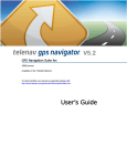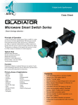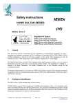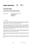
1
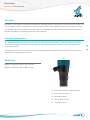
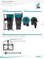
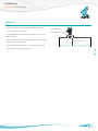
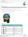
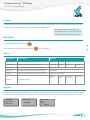
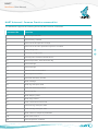
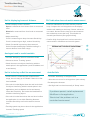
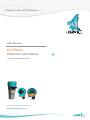
Sultan Sonar Manual Rev 1.0
A Higher Level of Performance
User Manual
MiniWave
Ultrasonic Level Series
Liquid Level Measurement
For more information, please visit >
www.hawkmeasure.com
>
Table Of Contents
MiniWave User Manual
Contents
Overview
3
HART
9
Overview
3
Principle of Operation
3
HART Universal /
Common Practice command list
9
Model Type
3
Troubleshooting
10
Dimensions & Wiring
4
Unit is displaying incorrect distance
10
Dimensions
4
Analogue trend is erratic/unstable
10
Flange
4
Unit is locked up or flat line measurement
10
Wiring
4
PLC indication does not match measurement
10
>
AutoSet fails
10
<
Installation
5
Mounting 5
Powering The Unit
6
Interface
6
Commissioning - Software
7
Startup
7
Main Menu
7
Setup
7
AutoSet
7
Advanced Settings
8
2
Model Types - Part Numbers 11
Model Type
11
Accessories
11
Specifications
12
Overview
MiniWave User Manual
Overview
MiniWave is a compact, loop-powered ultrasonic level transmitter for continuous measurement of liquids. As
a price leader, it does not compromise on good value; and provides effortless and intuitive operation. Easy
and flexible mounting combined with high chemical compatibility and 8-metre measuring range makes the
MiniWave suitable in multiple applications in all industries.
Principle of Operation
The MiniWave emits an ultrasonic pulse, which is reflected from the surface of the liquid being measured.
The reflected signal is processed using specially developed software to enhance the correct signal and
reject false echoes.
Automatic sensitivity control allows the unit to dynamically adjust and improve the received echoes for the
best possible measurement outcome.
A
Model Type
MWN1A - MiniWave with 2” NPT thread
MWB1A - MiniWave with 2” BSP thread
B
C
D
E
A - Removable lid with viewing window
B - Electronics housing
C - M20 cable gland
D - NPT or BSP thread
E - Transducer face
3
>
<
Dimensions & Wiring
MiniWave User Manual
Dimensions
Wiring
85mm (3.4”)
M20
Cable
Gland
23mm
(0.9”)
Flip Lid
to access
terminals
>
<
2" BSP or
NPT THD
M20 Blank Plug
47mm
(1.85”)
72mm (2.8”)
185 mm (7.3”)
-+
-+
52mm
(2”)
Flange
FA2NB-4 - 2” ANSI Polypropylene Flange for NPT threaded units
FA2BB-4 - 2” ANSI Polypropylene Flange for BSP threaded units
4 x Ø19mm (0.75”) HOLES THROUGH
120mm (4.7”) P.C.D.
2" NPT or BSP INTERNAL THREAD
15mm
(0.60”)
152mm (6.0”)
4
AutoSet
Set Lo Level
Set Hi Level
Set Lo
SCA
Installation
MiniWave User Manual
Mounting
• Sensor should be mounted 1/3 the diameter of the vessel from the vessel wall
• Unit should never be closer than 250mm (10") to the 2” NPT (MWN1A)
or
2“ BSP (MWB1A)
liquid surface
• Do not mount over or near objects which can interfere min 250mm (10”)
with the unit measurement
• Do not mount in the centre of a curved roof to avoid the potential of parabolic echoes
>
<
min 250mm (10”)
5
Installation
MiniWave User Manual
Powering The Unit
When power is applied, the unit will start up automatically. It will scroll through its boot diagnostics and display
the serial numbers, software version and model types for the amplifier and transducer
The selected Display Mode will be visible with a measurement.
The top right hand corner diagnostic indicates either the operating mode or the current output.
The unit will re-scan for the level whenever it is powered up.
Display Mode
Diagnostic
>
17.2mA
17.2mA
Space
Space
1.402m
1.402m
u
u
<
CAL
RUN
Setup
Display
Mode
Setup
mini wave
Display
Display Unit
Mode
Low
Level
Display
Unit
Hi
Level
Low
Level
Damping
Level
n Menu Hi
Setup
FailSafe
Damping
Display Mode
FailSafe
ced Interface
Display Unit
et
Low Level
Hi Level
Button
Action
Damping
Set Lo Level
Set Lo Level
No
Press and release
SCANNING
FailSafe
Yes
Autoset
Autoset
Advanced
Comms
Advanced
Echo
Size
Comms
Lock
Code
Echo Size
Analogue
Lock Code
Language
Analogue
Advanced
See (B) Autoset
See (B) Autoset
Autoset
Language
Comms
Echo Size
Lock Code
See (B) Autoset
Analogue
Navigation / Function
Language
2.597m
Access Main Menu
Select / Proceed
Press and hold for 3 seconds
Access Autoset Menu
Press and release
Cancel / Return
Re-activate unit
Press and Release
Scroll between live diagnostics
Scroll between menu options
Adjust parameters
6
Commissioning - Software
MiniWave User Manual
Main Menu
Setup
Autoset
Advanced
Setup
Display Mode
Comms
Autoset
Advanced Main Menu
Display Unit Setup
Echo Size Advanced
AutosetSetup
Startup
Display Mode
Comms
Low Level
Lock Code
See (B) Autoset
Advanced
Echo Size
Hi LevelDisplay Unit
Analogue
The MiniWave
uses
automatic
sensitivity
control
to
detect
and
maintain
the
level.
After
applying
power to the
Autoset
Lock Code
DampingLow Level
Language
See (B) Auto
unit allow 20-30 seconds for the unit
to
adjust
to
the
application*.
Analogue
FailSafe Hi Level
*For
best results ensure there is a
Damping
Language
liquid
level present in the application
FailSafe
or flat surface below the transducer
Main Menu
To access
the Main menu press
Flip Lid
to access
terminals
To access AutoSet menu press and hold Parameter
Description
Options
Display Mode
Set LCD measurement display mode
Level
Display Unit
Adjust displayed measurement unit
CenMetre
Low Level
Set Low level measurement point (4mA)
Adjustable
Set High level measurement point (20mA)
Adjustable
Damping
Adjust output response time & smoothness
Failsafe
% Level
Space
Metres
Feet
Inches
20.20mA
LastKnown
LstKnown
Adjustable in seconds
3.50mA
4mA
Set failsafe output
RUN
mini wave
High Level
>
CAL
<
1.402m
1.402m
Setup
-+
17.2mA
17.2mA
Space
for 3 secondsSpace
3.80mA
20mA
AutoSet
Use AutoSet to scan and program the unit High or Low level to the distance detected. After the scan you will be
prompted to accept the distance measured. The High and Low level can also be manually adjusted in 'Setup'.
AutoSet
Set Lo Level
Set Hi Level
7
Set Lo Level
SCANNING
Set Lo Level
No
Yes
2.597m
Commissioning - Software
MiniWave User Manual
Advanced Settings
Parameter
Description
CommType
Adjust HART protocol settings
Options
Device ID
BaudRate
Default 1
1200
The unit will target this echo size (measured in signal
voltage) during operation. High values can increase
EchoSize
stability but make the unit more susceptible to false
echoes. Lower values can make the unit less sensitive
0.4 - 2.49V
Default 0.59V
>
and less likely to see false echoes.
Tracking
Analog
<
Adjust tracking response time for application. The faster
Slow
the tracking, the more responsive the measurement is,
Medium
but it is less smooth the output signal.
Fast
InstaTrack provides pulse by pulse live measurement
InstaTrack
Adjust Analog output. Switch from 4-20mA to 20-4mA
4-20mA
Tune 4mA
and fine tune both 4mA current and 20mA current
20-4mA
Tune 20mA
Increase or decrease the unit's sensitivity to echoes.
Sensitivity
The unit uses dynamic & automatic sensitivity control.
0: lowest (default)
This parameter is a uniform adjustment to the overall unit
20: highest
sensitivity.
Reset
Lock Code
8
Restore all parameters to factory default
Enable / Disable lock code.
Enable / Disable
If enabled, select lock code number
Default Disabled
1-200
HART
MiniWave User Manual
HART Universal / Common Practice command list
The MiniWave supports the following Universal and Common commands
Command No.
Function
0
Read unique identifier
1
Read Primary Variable
2
Read current and percent of range
3
Read current and four predefined dynamic variables.
6
Write polling addr
>
7
Read loop configuration
<
8
Read Dynamic Variable Classifications
11
Read unique ident. associated with tag
12
Read message
13
Read message
14
Read PV sensor information
15
Read output information
16
Read final assembly number
17
Write message
18
Write tag, descriptor, date
19
Write final assembly number
20
Read Long Tag
34
Write damping value
35
Write range values
44
Enter / exit fixed current mode
57
Read unit tag, descriptor, date
58
Write unit tag, descriptor, date
59
Write number of response preambles
109
Burst mode control
110
Read all dynamic variables
9
Troubleshooting
MiniWave User Manual
Unit is displaying incorrect distance
PLC indication does not match measurement
• Confirm display mode is suitable.
• Connect a Multimeter in series with the powered Space is measured from Sensor face to measured loop. Compare the 'mA' diagnostic on the display
level. with the mA reading on the loop. If these values do
Material is measured from Low Level to measured not match, disconnect the loop wires and measure
level.
the resistance across the loop. This should not
• Adjust sensitivity -
exceed specification (See graph below)).
If unit is measuring too deep increase Sensitivity.
• Confirm High Level and Low Level are set to the If unit is measuring too high, reduce Sensitivity.
same values in MiniWave and control system.
• Check if material is present to be measured.
>
Unit will output and display FailSafe reading if it cannot detect a level within range.
<
Analogue trend is erratic/unstable
• Increase 'Damping' value for smoother trends
• Choose a slower 'Tracking' speed
• Check there are no objects interfering with the transit pulse in the application (such as ladders and cross beams)
Unit is locked up or flat line measurement
• Confirm there is material within measurement AutoSet fails
range, the unit may go to Failsafe if there is no flat level available.
• If the unit is locked higher than the real level check
for objects interfering with the transit pulse in the
• Increase 'Sensitivity' to a higher value
• Allow the unit to run for a longer time (one minute).
Re-attempt the Autoset.
• Set High and Low level manually in 'Setup' menu
application (such as ladders and cross beams).
Lower the Sensitivity. Re-locate the installation to avoid the interfering object.
• If the unit is locked lower than the real level confirm
the application is not within Blanking distance.
Increase Sensitivity until unit measures correct
level.
• Tracking speed may be too slow for the application. Increase Tracking speed
10
If problems persist, install replacement
MiniWave in the application.
'Bench test' the problem unit in a
controlled environment
Model Types - Part Numbers
MiniWave User Manual
Model Type
MWN1A - MiniWave with 2” NPT thread
MWB1A - MiniWave with 2” BSP thread
Accessories
FA2NB-4 - 2” ANSI Polypropylene Flange for NPT threaded units
FA2BB-4 - 2” ANSI Polypropylene Flange for BSP threaded units
>
<
11
Specifications
MiniWave User Manual
Frequency
Maximum Operating Pressure
• 50 kHz
• -0.5 to 3 bar (0 - 44 PSI)
Operating Voltage
Beam Angle
• 7 - 28VDC at the terminal
(residual ripple no greater than 100mV)
• 7o
Power Consumption
• 500mW @ 24VDC
Materials
• Transducer: PVDF
• Housing: Powder coated aluminum
Analog Output
Display
• 4 -20mA modulating output module with HART
(Recommended 250 Ohm @ 24VDC)
• 4 line graphic display (128 x 64)
Analog Resolution
• 14 bits
Communications
• 4 -20mA with HART
Blanking Distance
• 250 mm (10")
Maximum Range
• 12 metres (40ft)
Resolution
• 1 mm (0.04”)
Electronic Accuracy
• +/- 0.25% of maximum range
Operating Temperature
• -40°C to 60°C
12
Keypad
• 4 keys = CAL, RUN, UP, DOWN
Memory
• >10 years data retention
Enclosure Sealing
• IP67
Cable Entries
• M20 cable glands
Mounting
• 2” BSP Thread
• 2” NPT Thread
Typical Weight
1kg (2.2 pounds)
>
<
Contact
MiniWave User Manual
HAWK, Since 1988
Hawk Measurement Systems Pty Ltd (HAWK) was
established in 1988. It's founding members saw the
universal requirement of various industries requiring
importantly application experts making our customers
applications as efficient and consistent as possible.
Remote Innovation
improved process control and efficiency in their
HAWK understands the need for immediate technical
operations.
assistance.
We Can Help
HAWK understands the difficulties customers face
when seeking accurate level measurement. Every
application is different, involving a multitude of
environmental factors. This is where HAWK excels.
Our aim is to ensure that customers not only feel
comfortable with our technology, but that we also to
ensure a consistent and reliable solution is in place
for the long term. We believe that a combination
of application and product expertise, as well as
forward thinking and proactive support policies
are the foundation of successful customer-supplier
relationships.
Progressive Technical Support
HAWK believes that the future of the Level
Measurement Industry revolves around the quality
of pre and post sales - support. Our aim is for all
sales & support staff to be product experts, and more
The HawkLink 3G communication device allows
any computer with internet access and our free
GosHawk diagnostic & calibration software; to dial in,
calibrate, test, and check the performance of HAWK
products. This innovative system allows our Global
<
Support Team to assist with commissioning and
after sales service of HAWK equipment worldwide.
Measurement problems are addressed as they
happen; not days or weeks later.
Knowledge Sharing
HAWK believes that knowledge sharing is key to
creating long term relationships. Empowering our
customers and our worldwide distribution network,
whilst being available at all times to lend a helping
hand, is the perfect recipe for long-term solutions and
relationships. HAWK openly extends an invitation to
share our 25 years of level measurement experience,
and ensure that your day-to-day processes are
efficient, understood, and always working.
Hawk Measurement Systems
Hawk Measurement
(Head Office)
7 River Street
Middleton, MA 01949, USA
15 - 17 Maurice Court
Nunawading VIC 3131, AUSTRALIA
Phone: +61 3 9873 4750
Fax: +61 3 9873 4538
[email protected]
Phone: +1 888 HAWKLEVEL (1-888-429-5538)
Phone: +1 978 304 3000
Fax: +1 978 304 1462
[email protected]
For more information and global representatives: www.hawkmeasure.com
13
DOC-MW-MAN v1 17/14
All company or product names are registered trademarks or trademarks of their respective owners.