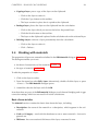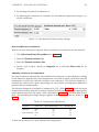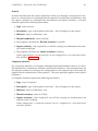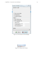
1
JPA TL
JPA Designer
Condensation Risk Analysis
Version 6.02a1 and above
ISSUE M AY 2 015
JPA TL Ltd.
Newcastle Business Village ,
33 Bellingham Drive ,
Nor th Tyneside Ind. Est.,
Newcastle upon Tyne NE12 9SZ
United Kingdom
E: [email protected]
W: www.techlit.co.uk
Contents
Contents
ii
1
JPA Designerbasics
1.1
IntroducingJPA Designer . . . . . . . . . . . . . . . . . . . . . . .
1.2
Gettingstarted . . . . . . . . . . . . . . . . . . . . . . . . . . . . .
1.3
Managingprojectsandcalculations . . . . . . . . . . . . . . . . .
1
1
3
9
2
R-valuecalculations
2.1
TheJPA DesignerR-valuemodules
2.2
Constructiondetails . . . . . . . .
2.3
Workingwithlayers . . . . . . . .
2.4
Workingwithmaterials . . . . . .
2.5
GroundfloorR-values . . . . . . .
2.6
Creatingreports . . . . . . . . . .
2.7
EditingtheProductsdatabase . . .
3
.
.
.
.
.
.
.
.
.
.
.
.
.
.
.
.
.
.
.
.
.
.
.
.
.
.
.
.
.
.
.
.
.
.
.
.
.
.
.
.
.
.
Condensationrisk
3.1
Theproblemofinterstitialcondensation . . .
3.2
CondensationriskanalysisinJPA Designer .
3.3
Viewingresults . . . . . . . . . . . . . . . . .
3.4
UsingtheBS 5250:1989calculationmethod
ii
.
.
.
.
.
.
.
.
.
.
.
.
.
.
.
.
.
.
.
.
.
.
.
.
.
.
.
.
.
.
.
.
.
.
.
.
.
.
.
.
.
.
.
.
.
.
.
.
.
.
.
.
.
.
.
.
.
.
.
.
.
.
.
.
.
.
.
.
.
.
.
.
.
.
.
.
.
.
.
.
.
.
.
.
.
.
.
.
.
.
.
.
.
.
.
.
.
.
.
.
.
.
.
.
.
.
.
.
.
.
.
.
.
.
.
.
.
.
.
.
.
.
.
.
.
.
.
.
19
19
20
22
26
32
33
36
.
.
.
.
40
40
41
46
49
1 JPA Designerbasics
1.1
IntroducingJPA Designer
Welcome to JPA Designer, the design and calculation program from JPA TL Ltd. This
manual describes how to use the JPA Designer to carry out R-value calculations and
interstitialcondensationriskanalysisforAustraliaandNewZealand1 .
JPA Designerincludesmanyfeaturestomakethecalculationprocesseasier:
• aproject-basedfilesystemwhichenablesyoutokeepallthecalculationsforone
developmentinsameprojectfile;
• calculationresultscanbeproducedasPDF filesforemailing;
• acomprehensivedatabaseofcommonmaterials;
WehopeyoufindJPA Designerausefulcalculationtool. Wearealwayshappytoreceive
comments, suggestions for improvements or proposals for enhancements to suit your
specificneeds.
Conventionsforthemanual
Themanualusesthefollowingconventions:
• <angledbrackets> forkeysonthecomputerkeyboard, e.g. the <Enter> key.
• the + signindicatesyoushouldholddownonekeywhilepressinganother, e.g.
<Alt+F> means‘holddownthe <Alt> keywhilepressingthe <F> key’.
• Boldtype indicatespartsofJPA Designer’sscreendisplays, e.g. the Ventilationrate
dialogue.
• Menu>option indicatesanoptioninamenuontheprogram’smenubar, e.g. Select
Edit>Primary heating system means click on the Edit menu and select Primary
heatingsystem fromthelist.
Thismanualusesthefollowingspecialterms:
1
JPA Designerincludesanumberofdifferentprogrammodules, some–notablytheSAP modules–are
intendedonlyforuseintheUK.WehaveaseparatemanualfortheUK onourwebsite.
1
CHAPTER1. JPA DESIGNER BASICS
2
• Dialogue(dialoguebox): asmallwindowwhichdisplaystextboxesorbuttonsfor
enteringdata.
• Radiobutton: asetoftwoormorerelatedbuttons-youcanonlyselectoneata
time.
• Tickbox: aboxwhichletsyouturnasettingon(ticked)oroff(notticked).
• Textbox: anareaonadialogueinwhichyoucantypewordsornumbers.
• List: a box on a dialogue which can be expanded to show a number of pre-set
options, usuallybyclickinganarrowontheright-handsideofthebox.
ManyfunctionsofJPA Designercanbeaccessedusingeitherthemenusorthetoolbars:
also, somemayalsohavekeyboardshortcuts. Toavoidrepetitionthismanualrefersonly
tothemenus.
Gettinghelp
Ifyouhaveaproblemwiththe functioning ofthesoftwarepleasefollowthesesteps:
• Download and install the latest version of JPA Designer from our web site (see
section 1.2 forinstructions)andseeifthatresolvestheproblem.
• ChecktheforumandFAQ onourwebsite(http://forum.techlit.co.uk)toseeifthe
problemisaddressedthere.
• Iftheproblempersists, emaildetailsoftheproblemto [email protected]. Please
include details of your computer system and attach sample files or PDF outputs
wherepossible. Wewillrespondassoonaswecan.
Ifyouhavedifficulty using theprogram(forexample, youareuncertainhowtoentera
layerinacondensationriskcalculation)pleasefollowthesesteps:
• Consulttheprogrammanualoron-linehelpsystem;
• ChecktheforumandFAQ onourwebsite(http://forum.techlit.co.uk)toseeifthe
queryisaddressedthere;
Ifyouarenewtocondensationriskcalculationsweofferdistancelearningandon-line
trainingtrainingcourses, whichprovideathoroughintroductiontothesoftwareandits
use. Youcanfindmoredetailsat http://www.techlit.co.uk/training.
CHAPTER1. JPA DESIGNER BASICS
1.2
3
Gettingstarted
ThissectionofthemanualdescribeshowtoinstallJPA DesigneronyourPC andexplains
howtheuserregistrationandon-linelicencecheckingsystemswork. Italsoincludes
instructionsonaddingyourcompanydetailsandlogotoreports.
Systemrequirements
JPA DesignerrunsonWindowsXP,Vista, 7and8(seeTechnicalNote2012/04). Apple
Macintosh users can run JPA Designer on aWindows virtual machine under Parallels
DesktoporVMWareFusion, oronaWindowsinstallationusingBootCamp(wedonot
offertechnicalsupportforinstallingJPA Designeronsuchsystems).
Whatever computer you are using it will require an internet connection to check the
validityofthelicence.
Installation
ToinstallJPA DesigneronyourPC:
1. Gotoourwebsiteatwww.techlit.co.ukand rightclick onthelinklabelled download JPA Designer: select Save link as or Save target as (the exact wording will
dependonwhichthebrowseryouareusing).
2. Savetheinstallerfile jsetup990.exe toyourPC (werecommenddownloadingthe
filetotheDesktop). Thedownloadisabout13MB.
3. Whenthedownloadiscompletedoubleclickonthefile jsetup990.exe. TheInstallShieldWizardconfiguresitselfand, afterafewmomentsopens.
Youmayseeasecuritywarningthatthepublisherofthefilecouldnotbeidentified.
Ifyoudo, click Run tocontinuetheinstallationprocess.
4. Click Next tocontinuewithinstallation. Theinstallerdisplaysthe LicenceAgreement. Tocontinuewiththeinstallationclick I acceptthetermsofthelicenceagreement, thenclick Next.
5. At the Customer information screen enter your name and company name and,
usingtheradiobuttons, selectwhetheryouwantJPA Designertobeavailabletoall
useraccountsonthecomputer, orjustone. (Werecommendyouselect all.) Click
Next.
6. Atthe ChooseDestinationLocation screenwerecommendyouacceptthedefault
settingsandinstallJPA Designerintothefolder c:\programfiles\jpatl\jpadesigner
981. Click Next. The installer will now copy the JPA Designer files onto your
computer.
7. Wheninstallationhasfinishedthe SetupComplete screenisdisplayed. Tickthe
boxlabelled Launchtheprogram andclick Finish. Theinstallerwillcloseand JPA
Designer willopen, showingyouthe ProjectManager window.
CHAPTER1. JPA DESIGNER BASICS
4
Userregistration
InordertouseJPA Designeryoumustentervaliduserregistrationdetailsandtheprogram
mustbeabletocheckthestatusofyourlicenceagainstourlicensingdatabase. Wesupply
theusernameandkeycodewhenyoubuyalicenceforamodule. Ifyoudonotenter
yourdetailsJPA Designerrunsin demonstrationmode andwillnotdisplaytheresultsof
calculations.
Toenterlicensedetailsforamodule:
1. Atthe ProjectManager window(Figure 1.1)select Edit>UserandSecurityCodes
fromthemenubar. The UserRegistration dialogueopens(section 1.2).
2. Inthesectionforthemodule(e.g. theU-valuemodule)enterthecompanyname–
exactlyassuppliedintheregistrationemail–inthebox Yourcompanyname.
Thecompanynameiscasesensitiveandshouldbeenteredexactlyasshowninthe
email: soif, forexample, youenter Limited, whenthecompanynamewiththekey
codecontained Ltd theprogramwillnotacceptthekeycode.
3. Copythekeycodefromtheregistrationemailandpasteitintothebottomboxon
the UserRegistration dialogue.
4. Clickthe Apply…code buttonforthemodule. Theprogramcopiesthecodeinto
the Keycode boxesforthemodule.
Ifyouhaveboughtseveralmodulesrepeatthestepsforeachone.
Figure 1.1: TheProjectManagerwindow
On-linelicencechecking
JPA Designerchecksthe validity ofyourlicenceforamodule thefirst timeyouopen
a calculation after the the program has started. It does this by contacting our on-line
licensingdatabaseandcheckingtheexpirydateformodule2 .
• Ifthecheckissuccessfulandthelicenceisvalidthemodulewillopen. (Theprogramwillrecordthedateandtimeofthatsuccessfulcheck).
2
Theprocessonlylooksforthecompanynameandchecksthelicencestatusandexpirydateonthe
database.
CHAPTER1. JPA DESIGNER BASICS
5
Figure 1.2: TheUserRegistrationdialogue
• Iftheprogramisunabletoconnectwiththedatabase(forexample, becauseyou
are using your lap-top away from your office) it will look at the date of the last
successfulcheck: ifthatislessthansevendaysagothenthemodulewillopen.
• Iftheprogramisunabletoconnectwiththedatabaseandthelastsuccessfulcheck
ismorethansevendaysagothenitwill not openthemodule.
• Ifthecheckissuccessfulandthelicenceisnotvalidthecalculationwillnotopen.
IfyouoftenuseJPA Designerawayfromtheofficetherearetwofeaturesyoucanuseto
preventproblemswiththelicencecheck:
• The ProjectManager toolbardisplaysthelengthoftimesincethelastsuccessful
licencecheck: providedthevaluesshownare green themodulewillopen.
• The Checklicenceon-line buttononthetoolbarwillforcealicencecheckand
re-setthetimesincethelastchecktozero. Youshouldforceacheckifyouexpect
nottohaveaninternetconnectionforafewdays.
Updates
JPA Designeriscontinuallybeingdevelopedtointroducenewfeatures: togetthebest
fromtheprogramitisworthmakingsureyouareusingthelatestversion. Youcanfind
CHAPTER1. JPA DESIGNER BASICS
6
theversionnumberbyselecting Help>About fromthemenubarinJPA Designerand
comparethatwiththeversionnumbershownonour website3 (www.techlit.co.uk).
Highernumbersandlettersindicatelaterreleases, withcharacterscomingearlierinthe
namebeingmoreimportantthatlaterones: so4.05a1willbemorerecentthan4.04c2,
and4.05b1morerecentthan4.04a4. Thethreedigit Build numberindicatesaminor
changeinaversion. Figure 1.3 showsthe About dialogueforJPA Designertogetherwith
theversionnumberonthewebsite: inthiscasethesoftwareisuptodate, asbothversion
numbersarethesame.
Theprocessforupdatingthesoftwareisidenticaltothatoforiginallyinstallingit4 (see
section 1.2).
Youcanfinddetailsofthechangesineachversionontheannouncementssectionofour
webforum5 .
Figure 1.3: TheAboutdialogueshowingtheversionnumber
OpeningandclosingJPA Designer
ToopenJPA Designer:
• Select Programs>JPA Designer>JPA Designer fromtheWindows Start menu.
A splashscreen(Figure 1.4)appearswhenyouopenJPA Designer. Thisallowsyoutoadd
newcalculationstoablankproject, ortoopenanexistingproject. Thereisanoption
nottodisplaythescreenwhentheprogramstarts-up.
TocloseJPA Designer:
• Select File>Exit fromtheJPA Designermenubar. Theprogramwillpromptyouto
closeanyfileswhichhavenotbeensaved.
3
www.techlit.co.uk
Ifyouareusingaversionearlierthan5.02a3youwillhavetouninstalltheprogramusingtheWindows
Add/removeprograms or Uninstallprograms controlpanel.
5
http://forum.techlit.co.uk/viewforum.php?f=13
4
CHAPTER1. JPA DESIGNER BASICS
7
Figure 1.4: ThenewsplashscreenforJPA Designer
UninstallingJPA Designer
TouninstallJPA Designer:
1. OpentheWindows Add/Removeprograms controlpanel(toaccessControlPanels
select Settings>ControlPanels fromthe Start menu).
2. SelectJPA Designerinthe Add/RemoveProgramsProperties dialogueandclick
Add/Remove. Windowswilluninstalltheprogramfilesandremoveitsicons.
UninstallingtheprogramwillnotremoveanyJPA Designerprojectfiles.
Addingyourcompanydetailstoreports
MostofthereportsproducedbyJPA Designercanbecustomisedtoincludeyourcompany
name, addressandlogo. Thedetailsareaddedusing Options dialoguefromthemain
ProjectManager window(see section 1.2). Thelogomustbea256colourBMP format
file6 .
ItisalsopossibletosetupdetailsforseveraldifferentcompanieswithinJPA Designer:
thesesetsofaddressdetailsandlogosarereferredtoasidentities(see section 1.2). You
canswitchbetweenidentitiestoproducecalculationreportswithdifferentaddressesand
logos.
Settingupaddressdetails
Tosetupyourcompanydetailsandlogoforreports:
6
Ifyouhavethecompanylogoinadifferentformat, suchasajpeg, tifforpng, youcanusethefree
PaintprogramwhichcomeswithmostversionsofMS Windows™toconvertittotherightformatandto
setthecorrectcolourdepth.
CHAPTER1. JPA DESIGNER BASICS
8
Figure 1.5: TheOptionsdialogue-Generaltab
1. IntheProjectManagerwindow, select Options fromthemenubar. The Options
dialogueopens.
2. Inthe General tabenteryourcompanyname, address, phoneandemaildetailsin
the Companyname&address section(see Figure 1.5).
3. Tickthe PrintLogo&Address box.
4. Enterthewordingofanydisclaimerswhichyouwanttoappearatthebottomof
U-valueandSAP reportsinthe U-valuedisclaimer and SAP boxes.
5. IfyouhaveenteredwordingfortheU-valueand/orSAP disclaimerstickthe Print
U-valuedisclaimer and/orthe PrintSAP disclaimer boxes.
6. Clickthe Logo&Signature tab.
7. Inthe Logoposition sectionenterthelocationofthe Top and Left sidesofthelogo,
relativetothepage, andenterthe Width ofthelogo. Alldimensionsshouldbein
millimetres. Itwillprobablytakesomeexperimentationtogetthelogopositionand
sizecorrect.
8. Enterthenameofthe Logofile, includingthe .bmp extension, thenclick OK to
closethedialogue.
9. Copyormovethelogofiletothefoldercontainingtheuserdata. OnWindows7
thiswillbe c:\ProgramData\JPA\JPA Designer.
Note: The Certificatesignatureposition andassociatedsettingsarenolongerin
use.
Settingupidentities
Theprocedureforsettingupidentitiesissimilartothatforsettingaddressdetails:
1. Enterthedetailsforthefirstcompanyasdescribedin section 1.2.
2. Re-openthe Options dialogue.
CHAPTER1. JPA DESIGNER BASICS
9
3. In the Identity list select the first blank identity (usually labelled Blank 1). The
Companyname&address anddisclaimerinformationwillbecleared.
4. Enterthedetailsforthesecondcompany, includingthedatain Logoandsignature
tab. Click OK toclosethedialogueandsavethedata.
5. Repeatsteps2–4foranyfurtheridentities.
As you add identities they will be added to the Identities list, using the Name of the
companyinthelist. Ifyouneedtoeditthedataforanyoneoftheidentities, selectit
fromthe Identities list, makethechangesandclick OK.
WhenyoucometocreateaPDF ofareportortoprintityouwillbeabletoselectone
oftheidentitiestousetheassociateddetailsintheheader. Notethatwhicheveridentity
youselectwhenproducingareport, thereportfooterwillalwaysshowthenameofthe
companyorindividualholdingthelicence.
1.3
Managingprojectsandcalculations
ThischapterexplainshowJPA Designerstorescalculationsanddescribeshowtowork
withprojectfilesandcalculations. Itdescribeshowtousecalculationtemplatestospeed
upthecalculationprocess.
Theprojectfile
JPA Designerorganisesandsavescalculationsinprojectfiles, whichhavetheextension
JDP.Youcansavemultiplecalculationsinthesamefile.
Calculationsarecreated, savedandmanagedintheJPA Designer ProjectManager window(Figure 1.1), whichlistsallthecalculationsinthecurrentproject.
Startinganewproject
WheneveryoustartJPA Designertheprogramcreatesanewblankprojectwhichyoucan
usestraightaway. Youcanalsocreateanewprojectatanytimebyselecting File>New
Project fromthemainmenu, orclickingthe NewProject buttononthetoolbar.
Youcanchangethedefaultprojectname A blankproject tosomethingmoreuseful:
1. Clickonceontheprojectnameandselect Edit>Renameselecteditem. The Project
name dialogueopens(Figure 1.6).
2. Enterthenewnameforyourproject, thenclickOK.
3. Theprojectisrenamed
Theprojectnamedoesnotaffectthecalculationsinanyway.
CHAPTER1. JPA DESIGNER BASICS
10
Figure 1.6: Changingthenameofaproject
Figure 1.7: TheProjectAddressdialogue
Addingprojectaddressdetails
Youcanenterclientaddressandsitedetailsforaproject, whichyoucanthencopyto
alltheindividualcalculationswithinthatproject. Youcanenterandeditthatinformationusingthe ProjectAddress dialogue(Figure 1.7). Youcanalsostoreclientaddress
informationtoreuseinotherprojects.
Toaddclientandprojectdetails:
1. From the menu bar select Edit>Project Address. The Project Address dialogue
opens.
2. Enterthedatabytypingitintotheappropriateboxes. Usethe <Tab> keytomove
betweenboxes.
Do nottryto enter datain the top lefthand box: thisbox is used for retrieving
detailsyouhavepreviouslystored.
3. Ifyouwanttostoretheclientdetailstore-uselaterclick Addtoclients.
CHAPTER1. JPA DESIGNER BASICS
11
4. Click OK whenyouhaveenteredallthedatayouneed.
Tocopytheprojectaddressdetailstoallthecalculationsinaproject:
1. Entertheaddressdetailsinthe ProjectAddress dialogue.
2. Click Passdown.
3. Click Yes attheconfirmationdialogue.
4. Oncethecopyingisdoneclick OK.
Youcanalsocopyprojectaddressdetailstoindividualcalculationsonceyouhaveopened
thecalculations(see section 2.1).
Tore-useexistingclientdatasimplyclickonthelistatthetopofthe Projectinformation
dialogueandselectaclientname(Figure 1.8).
Ifyouneedtoeditthedetailsheldforclientsclick Editclientslist thenmakethechanges
inthe EditClients dialogue.
Figure 1.8: Theclientnameandaddresslist
Settingthecalculationregion
JPA Designerisdesignedtocarryoutthethermalcalculationsrequiredindifferentregions
oftheworld. SomeregionsrequireU-valuecalculations, whileothersrequireR-value
calculations: someregionsonlyconsiderone-wayheatflowwhileothersrequiretwodirectionalheatflow(see Table 1.1. Theregionsettingsalsodeterminetheclimatedata
availableforcondensationriskanalysis.
Table 1.1: Regionalcalculationsettings
Region
Calculationtype
Heatflow
Asia
Australia
U-value
R-value
Ireland
MiddleEast
U-value
U-value
NewZealand
UK
R-value
U-value
Heat-out
Heat-in/
heat-out
Heat-out
Heat-in/
heat-out
Heatin/heat-out
Heat-out
Thecalculationregioncanbesetinthe ProjectAddress dialogue(see Figure 1.7):
CHAPTER1. JPA DESIGNER BASICS
12
1. Selectthe Region inthelist.
2. Click Setasdefault.
3. Allnewcalculationswillusethatregion.
Youcanoverridetheregionsettingforindividualcalculationsinthe ProjectInformation
&Options dialogue.
The multi-regional nature of JPA Designer is the reason some menu items for R-value
calculationsreferto U-value, ratherthan R-value.
Savingprojects
JPA Designerprojectaresavedinthesamewayasanyotherfile:
1. Fromthemenubarselect File>SaveProject. The SaveAs dialogueopens.
2. Selectthefolderintowhichtheprojectshouldbesaved, enteranamefortheproject
file.
BydefaultJPA Designerwilladdtheextension JDP toallfilenames.
3. Click Save. JPA Designersavestheprojectanddisplaysthefilenameontheprogram
titlebar.
BydefaultJPA DesignerwillsavefilesintotheJPA Designeruserdatafolder(onWindows
7usually c:\ProgramData\JPATL\JPA Designer981). Youcanspecifyadifferentdefault
folderbyspecifyingthe startup folderusingthe Options dialogue).
Figure 1.9: StartupfoldercontrolsintheOptionsdialogue
Tospecifythe startup folder:
1. Fromthemenubarselect Options.
2. Onthe General tabclickthe Select buttonforthe Startupfolder (item1in Figure 1.9).
3. Inthe BrowseForFolder dialogueselectafolderandclick OK.
4. ThefolderwillnowbethedefaultlocationforsavingJPA DesignerfilesandPDF
filesofcalculationreports.
Werecommendyouhavearegularback-upscheduleforyourdata.
CHAPTER1. JPA DESIGNER BASICS
13
Openingprojects
Toopenanexistingproject:
1. Fromthemenubarselect File>Openproject. The Open dialogueopens.
2. Selectthefileyouwanttoworkwith, thenclick Open. Theprojectopensinthe
ProjectManager window.
Addingcalculationstoaproject
Youcanaddnewcalculationstoaprojectinthe ProjectManager window. Toaddanew
R-valuecalculationorcondensationriskassessmenttoaproject:
1. Fromthemenubarselect Insert>U-valuecalculation. The Description dialogue
opens(Figure 1.10).
2. Typeanameforthecalculationinthe Description dialogue, e.g. warmroof, and
click OK.Thenewcalculationisaddedtotheproject.
WhennamingacalculationavoidusingtheWindowsrestrictedcharacters’/\: *?
< > |, otherwiseyouwillhaveproblemscreatingPDFsofcalculationreports(see
section 2.6 foramoredetailedexplanation.
Figure 1.10: TheDescriptiondialogue
UsingR-valuecalculationtemplates
JPA DesigneroffersarangeofstandardR-valuecalculations, whichyoucanusetospeed
upthecalculationprocessandminimiserepetitivework. WereferthesestandardcalculationsasR-valuetemplates. Eachtemplatecontainsthesameinformationasanormal
R-valuecalculationincludingelementdefinitionsandlayers.
Youcaneitherusethetemplate‘asis’withoutmodifyingit, oruseitasastartingpointto
produceyourowncalculation, butwhicheverrouteyouchose, thecalculationprocess
willbequicker.
TherearethreetypesofR-valuetemplate:
• standardtemplatesforroofs, wallsandfloors. Thesearegenericcalculationswhich
canbeadaptedbychangingmaterialsandthicknesses. Theyaresuppliedwiththe
program.
CHAPTER1. JPA DESIGNER BASICS
14
• manufacturers’templates. A numberofconstructionproductmanufacturershave
suppliedR-valuetemplatesfortypicalconstructionsfeaturingtheirproducts. The
templatesaresuppliedwiththeprogram7 .
• user-defined templates. These are calculations which you have previously performedandthensavedasatemplate, enablingyoutobuildupalibraryofcommonlyusedcalculations. See section 1.3 forinstructions.
InsertingaU-valuecalculationfromatemplate
ThecontrolsforinsertingR-valuecalculationsbasedontemplatesareatthebottomof
the ProjectManager window(Figure 1.11). ToinsertanewR-valuecalculationbased
onatemplate:
Figure 1.11: Thetemplateselectioncontrols
1. Inthe Categories listselectthe type oftemplateyouwant. Thatmaybeamanufacturer’scategory, oneofthedefaultcategories, oratemplategroupyouhavecreated
previously.
2. Inthe Templates drop-downlistpickthetemplateyouwishtouse.
3. Click NewU-valuefromTemplate. The Description dialogueopens.
4. Editthenameofthetemplatetosuityourproject, oracceptthedefaultname. Once
youareready, click OK.
5. A newR-valuecalculationisaddedtotheproject.
6. Youcannowopenandeditthecalculationbydouble-clickingonitsnameinthe
ProjectManager list.
Creatinguserdefinedtemplates
You can create templates from your own R-value calculations by saving them in JPA
Designertemplatefiles, whichhavethefileextensionJTF.Youcanhaveseveraldifferent
templatefileswhichallowsyoutosortthecalculationsintogroups: youmighthaveone
forwallcalculationsandoneforfloorcalculations, alternatively, youmightdividethem
intomasonryortimberframedcalculations.
Thesimplestwaytocreateatemplatefileistousethe ImportU-value featuretocollect
alltheexistingR-valuecalculationsyouwantavailableintooneprojectthensavethe
projectasatemplatefile.
ToimportanexistingR-valuecalculationtoaproject:
7
IfyouareamanufacturersofconstructionmaterialsyoucanaddR-valuecalculationswhichinclude
yourmaterialsintothesetoftemplateswhichisdistributedwithJPA Designer. OfferingR-valuecalculations
withyourmaterialsmakesiteasierfordesignerstoincludetheminR-valuecalculationsandspecifications
and helps to ensure the materials are included in calculations correctly. Please contact JPA TL Ltd for
informationandcurrentpricing.
CHAPTER1. JPA DESIGNER BASICS
15
1. StartanewprojectinJPA Designer: onthe File menuclick New.
2. Onthe File menuclick ImportU-valuefromanotherJPA Designerproject.
3. Inthe Open windowselectthefilewhichcontainsthecalculation.
4. Atthe ImportU-valuefromProject dialogue(Figure 1.12)selecttheU-valuecalculationfromthelistandclick OK.
5. TheR-valuecalculationisaddedtotheopenproject.
6. Repeattheprocesstoimportallcalculationsyouwantintotheproject.
Figure 1.12: TheImportU-valuedialogue
Youcan, ofcourse, createnewcalculationsforthetemplateifyouwantto.
The name which appears in the Categories list is taken from the project name in the
Project Manager window. So before you save a template file you should change the
project name to something which will help you identify the calculations from the list
(Figure 1.13)8 .
Tosetthe projectname:
1. In the Project Manager window double click on the project name – the default
valueis A blankproject.
2. Inthe ProjectName dialoguetypeanewnamefortheproject.
ThetemplatefilemustbesavedinthesamefolderastheotherJPA Designeruserdata
filesandintheJTF format. Tosaveaprojectasatemplate:
1. Onthe File menuclick SaveProjectasTemplate.
8
Thedefault A BlankProject willbenohelpatallafewweeksafteryouhavecreatedthetemplate.
CHAPTER1. JPA DESIGNER BASICS
16
Figure 1.13: Changingthe projectname
2. Entera Filename.
3. Set the folder to the user data folder (inWindows 7: c:\ProgramData\JPA\JPA
Designer).
4. Makesure Saveastype issetto JPA DesignerU-valueTemplate(JTF) andclick OK.
5. Yourtemplateprojectisnowincludedinthe Categories list.
Openingandclosingcalculations
Toopenacalculationfromthe ProjectManager window, either:
• doubleclickonthecalculationname; or,
• clickonceonthecalculationname, thenfromthemenubarselect Edit>Selected
item.
Tocloseacalculationandreturntothe Projectmanager windowclickthe Projectmanager buttononthetoolbar.
Duplicatingcalculations
Ifyouwanttocarryoutacalculationwhichisverysimilartoanexistingcalculationina
projectyoucanduplicatethecalculationandthenchangethecopy, leavingtheoriginal
calculationuntouched. Toduplicateacalculation:
1. Inthe ProjectManager windowclickonceonthecalculationtoselectit.
2. Fromthemenubarselect Edit>Duplicateitem. The Description dialogueopens.
CHAPTER1. JPA DESIGNER BASICS
17
3. Type a name for the duplicate calculation and click OK. A copy of the original
calculationisaddedtotheproject.
WhennamingacalculationavoidusingtheWindowsrestrictedcharacters’/\: *?
< > |, otherwiseyouwillhaveproblemscreatingPDFsofcalculationreports(see
section 2.6)foramoredetailedexplanation.
Youcannowworkwiththeduplicatecalculationintheusualway.
ImportingR-valuecalculations
Whenyouneedtore-useanexistingR-valuecalculationinanewprojectyoucanimport
acopyofthecalculationfromitsoriginalprojectintoanewone.
Toimportacalculationintothecurrentproject:
1. Onthe ProgramManager File menuselect ImportU-valuefromanotherJPA Designerproject.
2. Inthe Open dialogueselecttheprojectcontainingtheoriginalR-valuecalculation.
Click OK.
3. Inthe ImportU-valuefromProject dialogueclickonthecalculationtoselectit,
thenclick OK.TheR-valuecalculationiscopiedintothecurrentproject.
ImportingexistingR-valuecalculationsintoanewprojectisaquickwayofbuildingaset
ofR-valuetemplates(see section 1.3)
Renamingcalculations
Tochangethenameofacalculation:
1. Inthe ProjectManager windowclickonceonthecalculationtoselectit.
2. Fromthemenubarselect Edit>Renameselecteditem. The Name dialogueopens.
3. Enteranewnameforthecalculationandclick OK.The ProjectManager window
showsthenewname.
WhennamingacalculationavoidusingtheWindowsrestrictedcharacters’/\: *?
< > |, otherwiseyouwillhaveproblemscreatingPDFsofcalculationreports(see
section 2.6 foramoredetailedexplanation.
Changingthenameofthecalculationwillnotaffectthecalculationresults.
Deletingcalculations
CalculationscanbedeletedfromJPA Designerprojects.
WARNING:thereisnowayofrecoveringadeletedcalculation.
Todeleteacalculation:
1. Inthe ProjectManager windowclickonceonthecalculationtoselectit.
2. From the menu bar select Edit>Delete selected item. JPA Designer asks you to
confirmthedeletion.
3. Click Yes todeletethecalculationor No toabandonthedeletion. Ifyouclick Yes
thecalculationisremovedfromtheproject.
CHAPTER1. JPA DESIGNER BASICS
18
Mergingprojects
Usingthe Mergeprojects functionyoucancopyallthecalculationsinanexistingproject
into the currently open project. This can be useful if you have a number of standard
calculationsstoredindifferentprojectswhichyouneedtobringtogetherforaparticular
job. Mergingdoesnotchangetheprojectyouarecopying from.
Tomergecalculationsfromoneprojectintoanother:
1. In ProjectManager openorcreatetheprojectyouwantto receive thecalculations.
2. Fromthemenubarselect File>MergeaprojectfromdiskintothisProject. The
Open dialogueappears.
3. Selectthefilewhich contains thecalculationsandclick Open. JPA Designeradds
thecalculationstothecurrentprojectandliststheminthe ProjectManager window. Youcannoweditthemwithoutaffectingtheoriginalproject.
2 R-valuecalculations
2.1
TheJPA DesignerR-valuemodules
JPA DesignerofferstwoR-valuemodules:
• R-value2014 calculatesR-valuesforwalls, roofsandintermediateandsuspended
groundfloors.
• R-value2014Professional hasthefunctionalityofR-value2014andalsoperforms
condensationriskanalysisusingthemethodssetoutinISO 13788:2012.
TheprogramcarriesouttwoR-valuecalculationsforeachconstruction: aheat-incalculationandaheat-outcalculation1 .
R-valuecalculationsarecarriedoutintheR-valuemoduleby:
1. Enteringprojectinformation(section 2.1).
2. Enteringdataabouttheconstructionasawhole, includingtheelementtype(e.g.
wall, floor, roof)(section 2.2);
3. Definingthedifferentlayerswhichmakeuptheelement(section 2.4);
4. Printingcalculationresults, orcreatingPDF filesoftheresultsforemailing(section 2.6).
R-valueprojectinformation
JPA Designercanstoreclientandprojectdetailsforeachcalculationandthenaddthem
tocalculationreports. Youcaneithercopytheclientandprojectdetailswhichyouenteredinthe ProjectInformation dialogueinthe ProjectManager window, oryoucan
enternewdataintheR-valuemodules. Youcanalsosaveandre-useclientdata(section 1.3). Ineithercaseyoucanselectthe Region forthecalculation(see section 1.3 for
anexplanationofhowregionsettingsaffectcalculations).
TocopyprojectdetailsfromProjectManager:
1. IntheR-valuemoduleselect Edit>ProjectInformation fromthemenubar. The
ProjectInformation dialogueopens.
2. Clickthe Inherit button.
3. Atthepromptchoosewhetheryouwantthecalculationtoinherittheregionsettings
fortheprojectornot2 .
1
2
Thesearesometimesreferredtoassummerandwintercalculations.
Inmostcasesyouwillwanttoinherittheprojectregionsettings.
19
CHAPTER2. R-VALUE CALCULATIONS
20
4. AnyinformationyouenteredinProjectManageriscopiedtothe ProjectInformation dialoguehere.
5. Click OK.
Toenternewprojectdetails:
1. IntheR-valuemoduleselect Edit>ProjectInformation fromthemenubar. The
ProjectInformation dialogueopens.
2. Enterprojectinformationbytypingitintotheappropriatefields. Usethe <Tab>
keytomovebetweenfields.
3. Ifyouneedtousearegionotherthanthedefault, selectthenew Region inthelist.
4. Click OK whenyouhaveenteredallthedatayouneed.
Tocopyprojectdetailsfromthecurrentcalculationtoallothercalculationsinproject:
1. Entertheaddressdetailsinthe ProjectInformationandOptions dialogue.
2. Click Passdown.
3. Atthe Information dialogueclick Yes.
2.2
Constructiondetails
The thermal performance of building element will be affected by the type of element
anditspositionwithinabuilding. Theseconditionsaresetinthe U-valueConstruction
dialogue3 (Figure 2.1), whichacceptsdetailsof:
• Thetypeofelement(e.g. roof, wall, floor), togetherwithadditionalinformationfor
someelements(section 2.2).
• Theconditionsattheinternalandexternalssurfaces(see section 2.2).
Toenterdata:
1. Fromthemenubarselect Edit>Constructiontype. The U-valueConstruction dialogueopens.
2. Enteryourdataandclick OK.
Forsomeconstructions, suchasthosewithmechanicalfasteners, youmayfinditeasier
toentersomeofthedataintheconstructiondialogue after youhaveenteredthelayers
oftheelement.
3
NotethattheU-valueConstructiondialogueshowsanumberofoptionswhicharenotrequiredfor
R-valuecalculationsincludinglightsteelframeconstruction, twin-skinmetalroofingandcladding, and
themechanicalfixingscorrections.
CHAPTER2. R-VALUE CALCULATIONS
21
Figure 2.1: TheU-valueConstructiondialogue
Elementtype
JPA Designerrecognisesseveraltypesofelementwhichhavetobetreateddifferentlyin
thecalculationprocess. Usetheradiobuttonsinthe Elementtype sectiontoselectthe
typeoffloor, wallorroof. Forsomeelementsthereareoptionsforenteringadditional
information.
TheelementtypesrelevantforR-valuecalculationsare:
• Flatroof. A roofwithtypicallylessthan10ºpitch4 .
[+Pitchedroofwithhorizontalceiling. Typicallya‘coldroof’withtheinsulationapplied
betweenandovertheceilingjoists. Youmustenterthepitch(angle)oftheroof, measured
fromthehorizontal.]
• Pitched roof with ceiling at rafter line. A ‘warm roof’ with the insulation in the
planeoftherafters. Thiselementtypecanalsobeusedforpitchedroofswitha
horizontalceiling, wheretheresistanceoftheatticspaceisknown.
• Wall. Anyconstructionatanangleofmorethan70°tothehorizontal.
4
5
Theoptionsforinvertedroofsarenotrelevant.
Theoptiontoenterdataforthefixingsinrainscreencladdingisnotrelevant.
5
CHAPTER2. R-VALUE CALCULATIONS
22
• Floorotherthangroundfloor. A flooroveranopenspace(e.g. aparkingbay)or
anunheatedspace(e.g. anenclosedgarage).
• Solidgroundfloor. A floorwhichiscontactwiththegroundacrossitswholearea,
suchasgroundbearingconcreteslab.
• Suspendedgroundfloor. A floorwithaventilatedspacebelowthefloordeck, such
asabeamandblockfloorortimberjoistfloor.
Note: the Solidgroundfloor, Basementfloor and Basementwall elementsarenot
suitableorR-valuecalculations.
Youmayalsoenteradescriptionfortheelementinthe Description box, orselectone
fromthedrop-downlist. Thedescriptiondoesnotaffectthecalculation
Internalandexternalsurfaces
R-valuecalculationstakeaccountoftheheatflowattheinternalandexternalsurfacesof
anelementbymeansoftheinternalandexternal surfaceresistances. Thoseresistances
areaffectedbythedirectionofheatflowthroughtheconstructionandtheemissivityof
theexposedsurfaces.
Thesurfaceresistancesusedinthecalculationareshowninthetwopairsof SurfaceResistance boxes, witheachpairhavingaresistanceforoutwardandinwardheatflow. The
programautomaticallyadjuststhesurfaceresistancesaccordingtothetypeofelement
beingconsidered(section 2.2)andtheemissivityofthesurfaces, usingthevaluesfrom
theAIRAH Handbookshownin Table 2.1.
Thedefaultemissivitysettingis highemissivity. Virtuallyeverycommonlyspecifiedsurfacematerialhasahighemissivitysothereisrarelyanyneedtochangethedefault. You
can, ofcourse, replacedefaultresistanceswithyourownvalues.
Table 2.1: Airfilmresistances
Windspeed m/s
Heatflow
Element
Stillair
Horizontal
Up
Down
Up
Down
Up
Down
Horizontal
Any
Any
Any
45ºslope
22.5ºslope
6.00(winter)
3.00(summer)
0.5(internal)
2.3
Vertical
Any
Any
Any
Resistance(m2 K/W)
Highemittance Lowemittance
0.11
0.16
0.11
0.13
0.11
0.15
0.12
0.23
0.80
0.24
0.39
0.24
0.30
0.30
0.03
0.04
0.08
Workingwithlayers
EachR-valuecalculationisbuiltupbyinsertinglayerswhichcorrespondtothedifferentmaterialsintheconstruction. Forexample, aR-valuecalculationforacavityclay
masonrywallcouldhavealayertorepresenteachof:
CHAPTER2. R-VALUE CALCULATIONS
23
• theoutsidesurfaceresistance;
• theouterleafofbrickwork;
• thecavity;
• areflectivefoil;
• theinnerleafofmasonry;
• theplasterfinish;
• theinternalsurfaceresistance.
Figure 2.2: Thenewlayerwillbeinserted above theselectedlayer
Youcanaddlayerstothecalculationbyinsertingmaterialsfromtheprogram’sextensive
database, which includes data for generic materials and cavities, as well as branded
productsfromanumberofmanufacturers. Formanycommonconstructionsitispossible
toinsertallthelayersfromthedatabase. Ifyoucannotfindamaterialinthedatabase
thenyoucaninsertablanklayerandedittheinformationyourself.
Theprogramalwaysaddsanewlayerdirectly above thecurrentlyselectedlayer, so
in Figure 2.2 thenewlayerwouldbeinsertedabovethepolyethyleneandbelowthe
plywoodsheathing.
Whenyoustartacalculationyoushouldselectthelowestlayer(whichwillbetheinside
surfaceresistanceforwallsandroofs, andtheoutsidesurfaceresistanceforfloors)before
beginningtoaddlayers. Becauselayersareofthisitisquickertoworkfromoutsideto
insideforwallandroofcalculationsandfrominsidetooutsideforfloorcalculations.
InsertinglayersfromtheProductsdatabase
TheProductsdatabasecontainsawiderangeofmaterialsandcavitiesforuseinR-value
calculationsandisaccessedusingthe ProductsDatabase window(Figure 2.3).
The ProductsDatabase windowhasthreemainparts:
• The Categories box, whichisusedtoselectthetypeofmaterialyouwanttouse.
Categoriesofbrandedmaterialsareshownin bold, categoriesofgenericmaterials
in normal text and user categories in italics (see section 2.7 for information on
addingyourownmaterials).
CHAPTER2. R-VALUE CALCULATIONS
24
Figure 2.3: TheProductsDatabasewindow
• The Products box, whichyouusetoselectamaterialfromaparticularcategory.
• The Construction boxwhichshowstheorderoflayersintheconstruction.
ToinsertlayersusingtheProductsDatabase:
1. Selecttheexistinglayerwhichwillbe below thenewlayer.
2. Onthe Insert menuclick Layerfromdatabase (orclickthe Database buttononthe
toolbar). The ProductsDatabase dialogueopens.
3. Usethescrollbaronthe Categories boxtofindthemanufacturerortypeofmaterial
youneed, thenclickonceonthatcategory. The Products boxshowsthematerial
inthatcategory.
4. Clickonamaterialtoselectit, thenclick Addtoconstruction (alternativelyyoucan
doubleclickonthematerialinthe Productsbox). The Thickness dialogueopens.
If the material has a set thickness the layer will be added without the Thickness
dialogueopening.
CHAPTER2. R-VALUE CALCULATIONS
25
5. Enterthethicknessofthelayerthenclick OK.The Construction boxnowshows
thenewlayer.
6. Youcannowaddmorelayersfromthedatabase, usingthe Construction boxto
controlthepositionofthenewlayers.
7. Whenyouhavefinishedaddinglayersclickthe Close button. Themain R-value
windownowshowsthecalculationwiththenewlayersadded.
Productdatabasehints
Productcategoriesaresortedwithbrandedmaterialsfirst, followedbygenericand
usercategoriessortedinalphabeticalorder.
.
Ifyouarenotsurewhichcategoryaparticularmaterialbelongstoyoucanclick
Search tofindit.
You can use the Only show My database box to make the software only show
categorieswhichyouhaveadded.
Insertingblanklayersinacalculation
Toinsertanewblanklayer:
1. Selecttheexistinglayerwhichwillbe below thenewlayer.
2. Fromthemenubarselect Insert>Blanklayer (alternativelyyoucanpress <Insert>).
Thenewblanklayerisaddedtothecalculation above theexistinglayer.
3. Doubleclickonthelayertoopenitforediting.
Managinglayers
Onceyouhaveaddedlayerstoyourcalculationyouchangetheirorder, cut, copyand
pastethem, ordeletethem.
• Movingalayer:
– Clickandholdtheright-handmousebuttononthelayernumberatthelefthandsideofthewindow.
– Dragthelayertoanewposition.
– Releasethemousebutton
• Cuttingalayer: removesalayerfromthecalculationbutkeepsitavailableonthe
clipboard.
– Clickonthelayertoselectit.
– Clickthe Cut buttononthetoolbar.
– The layer is deleted from the calculation but remains on the clipboard for
pasting.
CHAPTER2. R-VALUE CALCULATIONS
26
• Copyingalayer: putsacopyofthelayerontheclipboard.
– Clickonthelayertoselectit.
– Clickthe Copy buttononthetoolbar.
– Thelayerremainsinplacebutiscopiedtotheclipboard.
• Pastingalayer: placesthelayerontheclipboardintothecalculation.
– Clickonthelayerwhichyouwanttobe below thepastedlayer.
– Clickthe Paste buttononthetoolbar.
– Thelayerontheclipboardisplacedinthecalculation above theselectedlayer.
• Deletingalayer: removesalayerpermanentlyfromthecalculation.
– Clickonthelayertoselectit.
– Click <Delete>.
2.4
Workingwithmaterials
Thepropertiesoflayersareenteredandeditedinthe EditMaterial dialogue(Figure 2.4).
Thedialogueenablesyoutoset:
• thebasiccharacteristicsofthematerial(section 2.4).
• thetypeofmaterial(section 2.4).
Toeditthepropertiesofalayer:
1. Clickonthelayertoselect.
2. Fromthemenubarselect Edit>Layer (alternatively, doubleclickthelayer, orpress
<Enter>). The EditMaterial dialogueopens.
3. Amendthedataforthelayerandclick OK.
Notethattherearepartofthe Editmaterial dialogue(suchthermalbridgingandairgap
correctionsettings)whicharenotusedinR-valuecalculations.
Basiccharacteristics
The Material sectioncontainsthebasicdataaboutthelayer, including:
• Description: thenameofthematerialoradescription, whichappearsinthecalculation.
• Code and Category : usedwiththedatabasetosortorentermaterials–butnotin
generaluse.
• Thickness: thecross-sectionalthicknessofthelayer, measuredinmm.
CHAPTER2. R-VALUE CALCULATIONS
27
Figure 2.4: TheEditMaterialdialogue
• Thermalconductivity: therateofconductionheattransferthrough1mofthematerial, measuredin W/mK. Usuallyreferredtoasthelambdavalue.
• Thermalresistance: theresistancetoheattransferprovidedbythelayer, measured
in m2 K/W.
• Vapourresistivity: therateoftransferofwatervapourthrough1mofthematerial,
measuredin MNs/gm.
• Vapourresistance: theresistancetowatervapourprovidedbythelayer, measured
in MNs/g.
Thefollowingtwovaluesareonlyrequiredfor κ-valuecalculations.
• Density: themasspercubicmetreofthematerial, measuredin kg/m3 .
• Specificheatcapacity: theamountofenergyrequiredtoraisethetemperatureof
onekilogramofthematerialbyoneKelvin(equivalentto1degreeCelcius). kJ/kg.
Two-directionalheat-flow
Some layers, primarily thermal insulation and air spaces, have different thermal resistancesdependingonthedirectioninwhichheatisbeingtransferred. Therearetwoways
ofaddressingthese two-directionalheatflowproducts:
CHAPTER2. R-VALUE CALCULATIONS
28
• byenteringtwothermalresistances; or,
• byadjustingtheresistanceofinsulationfortheambienttemperatureusingacorrectioncoefficient.
Figure 2.5: Two-directionalheattransfersettings
Heat-inandheat-outresistances
Whereyouhavebeengivenseparateheat-inandheat-outresistancesforthematerial:
1. Tick 2directionalheat-flowproduct (see Figure 2.5).
2. Enterthe ThermalresistanceIn.
3. Enterthe ThermalresistanceOut.
4. Set the Type of layer, usually to Composite for a solid and Clear cavity for an
airspace.
Adjustingresistancesfortemperature
Forsomeinsulationmaterialsthemeasuredthermalresistancecanbeadjustedaccording
tothedifferencebetweenthemeantemperatureacrosstheR-valuecalculationandthe
temperature at which the thermal resistance was measured. The thermal resistance is
increasedorreducedbyagivenpercentageforeverykelvinoftemperaturedifference
betweenthetwotemperatures.
Thethermalresistanceofinsulationismeasuredat23ºC,while Table 2.2 showsthemean
temperaturesusedforAustraliaandNewZealand. JPA Designerdeterminesappropriate
meantemperaturefromtheregionofthecalculation(section 1.3)anddirectionofheat
flow. Thestandardpercentagechangesappliedtodifferentinsulantsareshownin Table 2.3.
Table 2.2: Temperatureadjustments
Location
Heatflow
Australia
Out
In
Out
In
NewZealand
Meantemperature(ºC)
Adjustment(ºC)
15
30
12
27
–8
+7
–11
+4
Tohavetheresistanceofalayeradjustedfortemperature:
CHAPTER2. R-VALUE CALCULATIONS
29
Table 2.3: Temperatureadjustmentfactorsforinsulants
Material
Changeinresistanceperkelvin(%)
Glasswool, polyester, sheep’swool
Rockwool
Cellulose
0.65
0.39
0.52
1. Enterthe Thermalresistance ofthematerial.
2. Tick 2directionalheat-flowproduct.
3. Inthe Decreaseresistance listselecttheinsulationtype(see Figure 2.5). The percentage boxshowstheadjustmentbeingapplied. Iftheinsulationtypeisnotlisted
select Other*andenteravalueinthe Percentage box.
4. Setthe Type ofmaterial: thiswillusuallybe Normal or Composite.
Figure 2.6: Temperatureoptionsfortwodirectionalheatflowproducts
Optionsforadjustingresistances
Thethermalresistanceofinsulationisusuallymeasuredat23ºC.AS NZS 4859.1
requiresresistancestobeadjustedformeantemperaturesabovethat. However,
itiscommonpracticetoadjustresistancesatmeantemperaturesbelow23ºC
as
.
well. YoucanspecifywhetherJPA Designeradjustsonlyabove23ºC,oraboveand
below23ºC inthe Options dialogue.
Inthesection 2directionalheat-flowproducttreatment selecteither Adjustabove
23ºC or Adjustatalltemperatures (see Figure 2.6).
Typesofmaterialsandcavities
Layerswithinbuildingelementshavedifferentcombinationsofproperties: JPA Designer
recognises four types of material layer and five types of cavity. However, for R-value
calculationsonlythe ClearCavity isused.
Therestofthissectiondescribesthetypesoflayerandthedatarequiredforeachone.
CHAPTER2. R-VALUE CALCULATIONS
30
Normal
Normalmaterialshavethesamecompositionallthewaythrough, sothethermalresistanceofanormallayeriscalculatedfromthematerial’sconductivityandthickness, and
thevapourresistanceiscalculatedfromthethicknessandvapourresistivity. A normal
materialrequiresthefollowinginformation:
• Type: select Normal.
• Description : typeadescriptionofthelayer–thiswillappearonthereport.
• Thickness: enterinmillimetres, mm.
• Thermalconductivity: enterin W/mK.
• Theprogramcalculatesthe Thermalresistance in m2 K/W.
• Vapourresistivity: (onlyrequiredifyouwillbecarryingoutcondensationriskanalysis)enterin MNs/gm.
• Theprogramcalculatesthe Vapourresistance in MNs/g.
Whereappropriateanormalmaterialcanbeconfiguredasatwodirectionalheatflowproduct(section 2.4).
Compositematerials
Forcompositematerials, forexampleinsulation-backedplasterboard, thereisnodirect
linkbetweentheconductivity, thicknessandthermalresistance. Youmustthereforeuse
thethermalresistanceforthespecificconfigurationofthematerial(thiswillusuallybe
suppliedbythemanufactureroftheproduct). Thesameprincipleappliestothevapour
resistance.
A compositematerialrequiresthefollowinginformation:
• Type: select Composite.
• Description : typeadescriptionofthelayer–thiswillappearonthereport.
• Thickness: enterinmillimetres, mm.
• Thermalresistance: enterin m2 K/W.
• Vapour resistance: (only required if you will be carrying out condensation risk
analysis)enterin MNs/g.
Where appropriate a composite material can be configured as a two-directional
heat-flowproduct.
CHAPTER2. R-VALUE CALCULATIONS
31
Fixedvapourresistancematerials
Somematerials–suchasglassandmetals–havevapourresistanceswhichareeffectively
infinite, eveniftheyareusedinverythinlayers. The fixedvapourresistance materialtype
allowsthethermalperformanceofthesematerialstobehaveinthesamewayasnormal
materials(changingaccordingtothethickness), butallowstheirvapourresistancestobe
setasveryhighfixedvalues(typically 100.000 MNs/g.
Asmaterialswithfixedvapourresistancesbehavethesamewayasnormalmaterialsin
thermalcalculationsyouneedonlyusethetypeincondensationriskcalculations. A
fixedvapourresistancematerialrequiresthefollowinginformation:
• Type: select Fixedvapourresistance.
• Description: typeadescriptionofthelayer–thiswillappearonthereport.
• Thickness: enterinmillimetres, mm.
• Thermalconductivity: enterin W/mK.
• Theprogramcalculatesthe Thermalresistance in m2 K/W.
• Vapourresistance: enterin MNs/g.
Membranes
Membranes, suchasvapourcontrollayersorvapouropenroofingunderlays, aretreated
ashavingnothermalresistance. Theonlypropertytheyhaveistheirvapourresistance.
Membranesrequirethefollowinginformation:
• Type: select Membrane.
• Description : typeadescriptionofthelayer–thiswillappearonthereport.
• Vapourresistance: enterin MNs/g.
Membraneswithlowemissivitysurfaces
Membraneshavenodirecteffectonthermalcalculations. However, amembrane
.
whichhasoneortwolowemissivityfacesmayimprovethethermalperformance
ofaconstructionbyincreasingtheresistanceofadjacentcavities; thatisaddressed
inthecalculationbychangingtheresistanceofthecavities, notthemembrane.
Clearcavities
The thermal resistance of a cavity is not calculated directly from its thickness, but is
usuallyenteredasadefaultvalue, selectedonthedirectionofheatflowandthethickness
range. TheProductDatabasecontainsstandardresistances. Clearcavities, suchasthose
incavitywalls, requirethefollowinginformation.
• Type: select Clearcavity.
• Description : typeadescriptionofthelayer–thiswillappearonthereport.
CHAPTER2. R-VALUE CALCULATIONS
32
• Thickness: enterinmillimetres, mm.
• Thermalresistance: enterin m2 K/W.
Wherethecavityhastwodirectionalheat-flowfollow section 2.4 whensettingthe
thermalresistance.
• Vapourresistance: cavitieshaveavapourresistanceof 0.00 MNs/g.
Thecavityresistancecalculator(foundtotherightofthethermalresistancebox-see
Figure 2.4)usesthemethodinISO 6946:2007whichisnotemployedinAustraliaand
NewZealand.
2.5
GroundfloorR-values
ThestandardmethodofcalculatingR-valueshastobemodifiedforsuspendedground
floorstotakeaccountoftheunderfloorvoidandtheground.
Figure 2.7: TheGroundFloorDetailsdialogueforsuspendedgroundfloors
TocalculateanR-valueforasuspendedgroundfloor:
1. CreateanewU-valuecalculationinthe ProjectManager windowandopenitfor
editing(section 1.3).
CHAPTER2. R-VALUE CALCULATIONS
33
2. Enteranyprojectinformationinthe ProjectInformation dialogue(section 2.1).
3. Inthe U-valueConstruction dialoguesetthe ElementType to Suspendedground
floor.
4. Click OK.The GroundFloorDetails dialogueopens.
5. Enterthedatafortheground(Figure 2.7).
• Setthe Ventilation ofthesub-floorvoidaseither Non-ventilated or Ventilated.
• Setthecharacteristicsofthe Materialfacingthecavity as Highemissivity or
Lowemissivity.
• Theprogramwilldisplayasetofdefault sub-floorairfilmresistances basedon
theventilationandmaterialselections. Youcaneditthedefaultvaluesifyou
needto.
• Click OK.
6. Addtheremaininglayersofthefloorconstruction.
DonotusethismethodtocalculateR-valuesoffloorsoveropenorunheatedspacessuch
ascarparksorgarages; insteadselect Floorotherthangroundfloor intheConstruction
dialogueboxandproceedasusual.
2.6
Creatingreports
YoucanprintR-valuecalculationreportsorproduceaPDF filewhichcanbeopened
onanycomputerwiththefreeAdobeReadersoftwareinstalled. PDF filesareidealfor
emailingtopeoplewhoneedtoseetheresultsofthecalculationbutdonothaveJPA
Designer. ForbothprintandPDF thereportincludes:
• Projectinformation;
• Detailsoftheconstruction;
• A heat-outR-valuecalculation.
• A heat-inR-valuecalculation.
Toprintareport:
1. Onthe File menuclick Print (orclickthe Print buttononthetoolbar).
2. The SectionsToPrint dialogueopens(Figure 2.8). Ifyouhaveseveraluseridentities
(see section 1.2)selecttheoneyouwanttouseinthereportinthe Identities list.
The TIMSA logooptionisnotrelevantforAustraliaandNewZealand.
3. Ifyouwanttoincludeawatermarkoverthecalculationtick Printwatermarktext.
Youcanalsomodifythewording, angleandfontsizeofthedefaulttext.
4. Click OK.The Printpreview windowopens.
CHAPTER2. R-VALUE CALCULATIONS
Figure 2.8: TheSectionsToPrintdialogue
Figure 2.9: Printpreviewcontrols
34
CHAPTER2. R-VALUE CALCULATIONS
35
5. Usethebuttonsonthetoolbartoviewsuccessivepagesofthereport, thenclick
the Print buttontoprintthepages(Figure 2.9).
TocreateaPDF report:
1. Onthe File click CreatePDF.A dialogueasksifyouwanttoopenthePDF whenit
iscreated.
2. Select Yes or No. The SectionsToPrint dialogueopens(Figure 2.8).
3. Ifyouhaveseveraluseridentities(see section 1.2)selecttheoneyouwanttouse
inthe Identities list.
The TIMSA logooptionisnotrelevantforAustraliaandNewZealand.
4. Ifyouwanttoincludeawatermarkoverthecalculationtick Printwatermarktext.
Youcanalsomodifythewording, angleandfontsizeofthedefaulttext.
5. Click OK.The Printpreview windowopens.
6. Usethebuttonsonthetoolbartoviewsuccessivepagesofthereport, thenclick
the Print buttontoprintthepages(Figure 2.9). TheprogramwillthencreateaPDF
fileofthecalculation.
*ThenameofthePDF filewillincludetheJPA Designerfilenameandthecalculationname, sothecalculation tilehungwall inaproject TheMeadows willbe
called TheMeadows.JDPtilehungwall.PDF.
7. ThefilewillbesavedintotheJPA Designerprogramdatafolderorinthestart-up
folderyouhavespecified(see section 1.3).
Note: asWindowsdoesnotallowcertaincharacterstobeusedinfilenamesyou
shouldensurethecalculationnamesinJPA Designerdonotcontainthosecharacters, otherwisePDF creationwillfail. Therestrictedcharactersare: ’ /\: *? < >
|.
Youcanchangetheprintersettingsbyselecting File>Printersetup fromthemenubar.
It is also possible to produce PDF reports of all the R-value calculations at once. In
the ProjectManager windowonthe File menuclick PrintallU-valuecalculationsin
thisprojecttoPDFs. Theprogramwillthenofferthe SectionstoPrint dialoguebefore
creatingthePDFs.
Addingnotestoreports
Youcanaddnotestothereportofacalculation, whichcanbeusedtoexplainparticular
featuresofthecalculationortohighlightassumptionsmadewithinit.
Toaddnotesopenthe U-valueconstruction dialogueandclickonthe PrintReportNotes
tab. Youcanthenenteryourwording(Figure 2.10). Thenotestextwillappearbetween
thelayerslistandthefinalresult.
CHAPTER2. R-VALUE CALCULATIONS
36
Figure 2.10: ThePrintReportNotestabintheU-valueConstructiondialogue
Customisingreports
YoucancontrolmanyaspectsoftheappearanceofJPA Designer’scalculationreports:
• Selectingtheprinter: IntheU-valuemoduleselect File>Printersetup. Youcan
select the printer and paper source. It is possible to set the page orientation to
landscaperatherthanportrait, butthereportsarenotdesignedforlandscapeformat.
• Changingthefontusedinreports: IntheU-valuemoduleselect File>Font. Thenin
the Font dialogue. setthetypeface, styleandsize. ThedefaultisArialregular, 10
pt. Largersizesmaycauseproblemsonthepagewithcolumnsoverflowing. Note
also, thatsomefontsarewiderthanothers, evenatthesamepointsize, soitworth
testingfontsettings.
• Pagemargins: Thesearesetinthe General tabofthe Options menu. Therearetwo
Top settings, oneforthefirstpageandoneforthesecondpage. Thisistoallow
youtoprintcalculationsontoheadedpaper, withprintingonthefirstsheetstarting
lowerdownthepage.
• Addingyourlogoandaddress: Youcanaddyourlogoandcontactdetailstocalculationreports: see section 1.2.
• Addingadisclaimertobeshownatthebottomofcalculationreports: Enterthe
disclaimer text in the U-value disclaimer box on the Options dialogue General
tab.
• Includingthetotalconstructionthicknessinthecalculationreport: Inthe Other
tabofthe Options dialoguetick PrinttotalthicknessonU-valuereport. Thetotal
thicknesswillthenappearoncalculationreportsbelowthelayerlist.
2.7
EditingtheProductsdatabase
TomakeU-valuecalculationseasierallJPA DesignerU-valuemodulesincludethe Productsdatabase, whichprovideskeydataongenericconstructionmaterialsandcavities,as
wellasdataonbrandedproductsfromanumberofmanufacturers. Thissectionexplains
howyoucanaddfrequentlyusedproductstothedatabase.
Thematerialswithinthedatabaseareorganisedintothreecategories:
• Brandedproductsfrommanufacturers, shownin bold inthecategorieslist;
CHAPTER2. R-VALUE CALCULATIONS
37
• Genericmaterials, showninnormaltypeinthecategorieslist;
• User-definedmaterials, shownin italics inthecategorieslist.
Whilstyoucancreate, editanddeleteuser-definedcategoriesandmaterials, youcan
noteditordeletebrandedorgenericcategoriesormaterials. However, youcanclone
agenericorbrandedmaterialandmakechangestothecone, leavingtheoriginaluntouched.
Tomakechangestothe Productsdatabase youmustfirstopenthe Editdatabase dialogue
(Figure 2.11)byselecting Edit>Database fromthemainmenu.
Figure 2.11: TheEditDatabasedialogue
Toaddauserdefinedcategory:
1. Clickthe Newcategory button.
2. Enterthenameofthecategoryinthe Newcategory dialogue.
3. Click OK.Thenewcategoryiscreated.
Torenameanexistinguserdefinedcategory:
1. Selectacategorybyclickingonit.
2. Clickthe Editcategory button. The Editcategory dialogueopens.
3. Enteranewnamethenclick OK.Thecategoryisrenamed.
CHAPTER2. R-VALUE CALCULATIONS
38
Tocloneacategory:
1. Selectthecategorytoclonebyclickingonit.
2. Clickthe Clonecategory button. The Clonecategory dialogueopens.
3. Enteranameforthenewcategoryandclick OK.
4. A newcategorywillbecreated, containingcopiesoftheoriginalmaterials.
Todeleteauserdefinedcategory:
1. Selectthecategorytodelete.
2. Clickthe Deletecategory button. An Information dialogueasksyoutoconfirmthe
deletion.
3. Click Yes todeletethecategory, No tokeepit.
Toinsertanewmaterialinauser-definedcategory:
1. Selectthecategoryinwhichyouwanttocreatethenewmaterial.
2. Clickthe Newproduct button. The Editmaterial dialogueopens.
3. Completethe Editmaterial dialogue(section 2.4).
4. Click OK.Thenewproductisaddedtothecategory.
Toeditanexistinguserdefinedmaterial:
1. Selecttheproductyouwishtoedit.
2. Clickthe Editproduct button. The Editmaterial dialogueopens.
3. Makethechangesinthe Editmaterial dialogue(section 2.4).
4. Click OK.Theproductinformationisupdated.
Tocloneanexistingproductinauserdefinedcategory:
1. Selecttheproductandclickthe Cloneproduct button. A copyoftheproductwill
beinsertedinthecategory.
2. Clickontheclonetoeditit.
Todeleteaproductfromauser-definedcategory:
1. Selecttheproductyouwishtodelete.
2. Clickthe Deleteproduct button. Theproductisdeleted.
CHAPTER2. R-VALUE CALCULATIONS
39
Figure 2.12: TheSearchDatabasedialogue
Youcansearchthedatabasetofindspecificproducts:
1. Clickthe Search button. The SearchDatabase dialogueopens(Figure 2.12).
2. Inthe SearchDatabase dialogueenterthetextyouwanttosearchforandthedirectiontheprogramshouldsearchthroughthedatabase(forwards or backwards).
3. Tickthe Ignorecase boxifyouwantthesearchtoignorecapitalsandlower-case
letters.
4. Click Find first to start the search. The program will display the first matching
productinthe Products pane.
5. Click Findnext togoontothenextmatchingproduct.
6. Whenyouhavefoundtheproductyouwantclick Close toclosetheSearchdialogue.
Whenyouhavefinishedworkingonthedatabase, clickthe Close buttontoreturntothe
mainU-valuewindow.
Shortcodes
Youcanassigncodestouserdefinedmaterialsasyouentertheminthedatabase. The
shortcodescanthenbeusedforrapiddataentryusingtheProductsdatabase. Youcan
alsouseshortcodestodeterminetheorderinwhichproductsandmaterialsarepresented
withincategories, tospeedupdataentryforcommonconstructions.
Tosortthedatabasebyshortcodesyoumustfirstassignshortcodestothematerials; use
anumberingsystemwhichmatchestheorderinwhichyouwantthematerialstoappear.
Onceyouhaveassignedshortcodesyoushouldclickonthe Sortonshortcode tickbox
inthe Productsdatabase dialogue(Figure 2.3).
3 Condensationrisk
3.1
Theproblemofinterstitialcondensation
Condensationoccurringwithinbuildingelements–interstitialcondensation–cancause
substantialdamagetothebuildingfabricandreducetheeffectivenessofthermalinsulation1 . Bycarryingoutcondensationriskanalysis(CRA) youcanidentifyconstructions
whicharelikelytobeatriskofcondensationand, wherenecessary, makemodifications
tothedesign.
JPA Designerassessestheriskofinterstitialcondensationusingthesteady-statemethod
definedinISO 13788:20122 , whichusesmeanmonthlytemperaturesandrelativehumiditiestoassesstheriskofinterstitialcondensationoveratwelvemonthperiod. The
methodprovidesageneralassessmentofsuitabilityoftheconstruction, butdoesnotaddressairmovementwithintheconstruction, nordoesittakeaccountoftheeffectsof
capillarymoisturetransfer.
1
Forfurtherinformationonthecausesandeffectsofcondensation, andguidanceonreducingproblems
seetheABCB handbookCondensationinBuildings, availablehere: http://www.abcb.gov.au/educationevents-resources/publications/abcb-handbooks
2
ISO 13788:2012Hygrothermalperformanceofbuildingcomponentsandbuildingelements–Internal
surfacetemperaturetoavoidcriticalsurfacehumidityandinterstitialcondensation–Calculationmethods.
40
CHAPTER3. CONDENSATION RISK
3.2
41
CondensationriskanalysisinJPA Designer
Condensation risk analysis determines whether condensation is likely to occur at the
interfacesbetweenthelayersofmaterialwhichmakeuptheconstruction3 . Usingthe
hygrothermalpropertiesofthematerials(section 3.2)andtheenvironmentalconditions
(section 3.2)theprogramlooksateachinterfaceintheconstructionandcalculates:
• theamountofcondensatedepositedorevaporatedduringeachmonthofayear;
• themaximumamountofmoisturedeposited;
• theaccumulatedmassofwatercomparedtototalevaporationduringtheyear;
• theannualmoisturebalance.
Youcanthenusetheresultstoassessthesuitabilityoftheconstructionforthatenvironment.
Tocarryoutcondensationriskanalysis:
1. Definetheelementinthesamewayasyouwouldforathermalcalculation(section 3.2).
2. Settheenvironmentalconditions(section 3.2);
3. Viewtheresults(section 3.3).
ForAustraliaandNewZealand, wherecavitiesandinsulantshavedifferentproperties
accordingtothedirectionofheattransfer, thecondensationriskmodulehastoselect
whethertousetheheat-outorheat-inpropertiesforanalysis.
Foreachmonththeprogramcomparestheinternalandexternaltemperatures:
• whereamonthhasahigherinsidetemperaturetheanalysisusestheheat-outvalues
ofmaterials;
• whereamonthhasahigherexternaltemperaturetheanalysisusestheheat-invalues
ofmaterials.
Definingtheconstruction
Tocarryoutcondensationriskanalysisyoumustsetthethermalresistanceandvapour
resistanceofeachlayerwhichmakesuptheelement, usingtheappropriatemethodsfor
eachtypeoflayer:
• Normal materials: Enterthe thickness, thermalconductivity and vapourresistivity.
JPA Designerwillcalculatethe thermalresistance andthe vapourresistance.
3
Themodulecannotcarryoutcondensationriskanalysisforgroundfloors, basementsnorconstructionscontainingvariablelayers; neitherwillitcalculatetheriskofsurfacecondensation.
CHAPTER3. CONDENSATION RISK
42
• Composite materials: Enterthe thermalresistance and vapourresistance. Although
the thickness isnotrequiredforthecalculation, settingthe thickness ensuresthe
Dewpointgraph(Figure 3.4)looksright.
• Fixedvapourresistance materials: Thesearedesignedtobeusedincondensation
riskanalysistorepresentmaterialssuchasmetalswhichhaveveryhighresistances
evenwhenusedinthinlayers. Enterthe thickness, thermalconductivity andthe
vapourresistance.
• Membranes: Enterthe vapourresistance.
• Cavities: Enterthe thermalresistance. Thevapourresistanceofacavityisalways
zero. Enterthe thickness toensurethetheappearanceoftheDewpointgraph.
Thedataforeachtypeofmaterialandcavityisdescribedinmoredetailin section 2.4.
Ifyouhavealreadycarriedoutthermalcalculationsonthesameconstructionyouneed
onlycheckthatthevapourresistivityorresistancefiguresarecorrect.
Unitsofvapourresistanceandresistivity
JPA Designer uses the vapour resistivity with units of MNs/gm and vapour resistance
with units of MNs/g. If material data is quoted as µ or sd values, multiply by five to
obtain the resistivity or resistance respectively. You can find guidance on converting
fromEuropeanunitsandfrompermeabilityandpermeancefiguresinAnnexesE.7and
E.8ofBS 5250:2011.
Environmentalconditions
Thecondensationriskcalculationrequiresmeanmonthlydatafortheexternaltemperatureandrelativehumidityandtheinternaltemperatureandrelativehumidity.
Externaltemperatureandhumidity
Theexternalconditionsdependuponthebuilding’slocation. JPA Designerincludesexternal temperature and humidity data for each of the 69 climate regions in NatHERS
aswellasanumberofweatherstations., allowingyoutoselectthenearestlocationto
theprojectsite. Ifyouhaveenvironmentaldataforalocationyoucaneitherenterthat
directly, oraddittotheprogram’sstandarddatasets.
Internaltemperatureandrelativehumidity
Internalenvironmentaldatacanbe:
• derivedfromtheexternalconditionsusingthemethodinISO 13788AnnexA.1.
Thisissuitablefordwellingsorofficeswithnoairconditioning.
• enteredasdesignconditions. Thisisintendedforbuildingswithcoolingand/ordehumidificationsystems. Youcansetdesignconditionsforanindividualcalculation,
orcreateanduseanewdataset(section 3.2).
CHAPTER3. CONDENSATION RISK
Figure 3.1: TheEnvironmentalConditionsdialogue
43
CHAPTER3. CONDENSATION RISK
44
Settingenvironmentalconditions
Theenvironmentalconditionsforcondensationriskanalysisaresetinthe Environmental
Conditions dialogue(Figure 3.1).
Tosettheenvironmentalconditions:
1. Onthe Edit menuselect Editenvironmentalconditions.
2. Selectthe Buildinglocation fromthelist. Onceyouhavedonethattheexternal
temperatureandrelativehumiditycolumnsarefilledin.
Thelistonlyshowslocationsfortheselectedregion(section 1.3). Thelocations
starting CZ areclimatezonesbasedontheNatHERS dataset.
3. Toderivetheinternalconditionsfromtheexternalconditions:
a) Tick**Calculateinternalconditionsbasedonexternalconditions,
b) At Climate select Continentalortropical.
c) At Occupancy select Normal or High.
Highoccupancywillsetahighermoistureload.
d) Thedatain the internal temperatureand relative humidity columns will be
adjusted.
4. Alternatively, toselectadatasetforinternalconditions:
a) Tick Usedesigndataforinternalconditions.
b) Selectasetofconditionsfromthelist.
Ifthelistdoesnothaveasuitablesetofinternalconditionsyoucancreateone:
see section 3.2).
5. Ignorethe Risklevel list.
a) Thedataintheinternaltemperatureandrelativehumiditywillbeset.
Creatingnewdatasets
Youcanbuildupandsavesetsofinternalandexternalenvironmentalconditionstouse
incondensationriskanalysis. Thisisparticularlyusefulwhenexaminingair-conditioned
buildingswhichhavedesignvaluesfortemperatureandhumidity.
Userdataisstoredinafile Env_user.txt whichiskeptwiththeotheruserdatafilesin
c:\ProgramData\JPA\JPA Designer (filelocationcorrectforWindows7-seeTechnical
note2012/01forotherversionsofWindows). Currently, theonlywaytoadddatasetsisto
edit Env_user.txt inatexteditor, suchasNotepad(Figure 3.2). Beforeediting Env_user.txt
makesureJPA Designerisnotrunning.
Within Env_user.txt thedataforanexternallocationoraninternaldesignconditionison
oneline, witheachlineseparatedbyareturn. Oneachline, thedifferentitemsofdata
areseparatedbythepipecharacter, |, withnospacesbeforeorafterthepipe. Thefinal
characteroneverylineisalsoapipe.
Thedataitemsare:
CHAPTER3. CONDENSATION RISK
45
Figure 3.2: Editingthe Env_user.txt file
• Item1: whetherthesetisforinternalconditions, 0, orexternalconditions, 1.
• Item2: whetherthesetissystemdata, 0, oruserdata, 1.
• Item3: atextdescriptionofthedataset. Thisappearsinthe Buildinglocation or
internalconditions lists, whicharesortedalphabeticallyusingthetextdescription.
Thisitemcanstartwiththetildecharacter(∼), whichdoesnotappearonlists, but
controlsthewayinwhichitems4–27areinterpreted.
• Items4–27: thesearethemonthlytemperatureandrelativehumidityfigures. Temperaturesshouldbeenteredindegreescentigradeandrelativehumidityasapercentage. Theorderofthedatadependsonwhetheritem3startswithatilde(∼).
– If item 3 has a tilde the mean monthly temperatures should be entered in
a sequence starting with January, followed by the relative humidity figures,
startingwithJanuary(so: Jan temp|Feb temp| … |December temp|Jan
%rh|Feb %rh| etc.)
– Ifitem3hasnotildethetemperatureandrelativehumidityvaluesforeach
monthshouldfolloweachother(so: Jan temp|Jan rh|Feb temp|Feb
%rh| etc).
• Item 28: the country code. UK, 0. Republic of Ireland, 1. Australia, 2. New
Zealand, 3. Asia, 4. MiddleEast, 5.
• Item29: appliestoexternalenvironmentalsetsandindicateswhetherinternalconditionsshouldbecalculatedonthebasisofcontinentalconditions, 1, ormaritime
conditions, anyothervalue. Thisitemisusedonlywheninternalconditionsareto
bederivedfromtheexternalconditions: itisnotusediffixedinternalconditions
arespecified.
Asanexample:
1|1|Newcastle Airport|3.4|92|…|4.2|89|0|0|
Thisshows:
• Externaldata(1).
• Userdata(1)
• Location, withnotilde.
CHAPTER3. CONDENSATION RISK
46
• Pairedmonthlyvaluesfortemperature(3.4and4.2)andrelativehumidity(92and
89).
• UK (0)
• Maritimeclimate(0).
Oncetheenvironmentalconditionshavebeenenteredandsavedin Env_user.txt andJPA
Designerstarted, thenewdatasetswillshowupinthe internalconditions list. Notethat
theconditionswillonlyshowiftheirregionmatchestheregionselectedforanalysis.
IfthereareseveralusersofJPA Designerwithinthesameorganisationthe Env_user.txt
filecanbesetupononePC thencopiedtotheothers, ensuringeveryoneisusingthe
samedatasets.
3.3
Viewingresults
Youcanviewtheresultsofcondensationriskanalysisinthreeformats:
• Asmonthbymonthdata, intheISO CondensationTable(section 3.3).
• Asagraph, intheDewpointgraph(section 3.3).
• Insummaryform, intheResultstable(section 3.3).
ISO CondensationTable
The ISO CondensationTable showstheamountofcondensatepredictedateachinterface
intheconstruction, andisthemostaccuratemeansofviewingtheresultsofananalysis
toISO 13788.
Toviewthe ISO CondensationTable: onthe View menuselect ISO CondensationTabler.
Theupperpartofthewindow(Figure 3.3)showstheinterfaceswithintheconstruction.
When you select an interface by clicking on it, the lower half of the table shows the
amountofcondensationpredictedatthatinterface. Itshowstheamountofcondensate
depositedorevaporatedeachmonth, gc, andtheaccumulatedcondensateattheendof
eachmonth, Ma, bothmeasuredin g/m2 . A negativeamountofcondensateindicatesthe
amountofmoisturepredictedtoevaporateinthatmonth.
Theresultsalwaysstartwiththefirstmonthinwhichcondensationispredicted: ifnocondensationispredictedinanymonthresultsstartwithJanuary. Guidanceoninterpreting
resultsisgiveninISO 13788andBS 5250.
TheDewpointgraph
In condensation risk analysis the dew point is the temperature at which air would be
saturated with vapour. Condensation occurs when the temperature at a point with in
theconstructiondropsbelowdewpointandtheaircannotsupportallthewatervapour,
resultinginsomeoftheexcessbeingdepositedasliquidwater.
The Dewpointgraph isavisualisationoftherelationshipbetweenthepredictedtemperaturethroughanelementandthedewpoint. Theorientationofthe Dewpointgraph is
determinedbythebuildingelement: wallsareshownwithlayersrunningverticallyand
roofswithlayersrunninghorizontally.
Thegraphshowstwolines:
CHAPTER3. CONDENSATION RISK
47
Figure 3.3: ISO 13788Condensationtable
• thetemperaturegradientthroughtheconstruction, calculatedforeachinterface,
showninred; and,
• thedewpointateachinterface, showninblue.
Thelinesareplottedforthemonthwiththeworstcondensationconditions.
Where the two lines do not touch the actual temperature is above dew point and no
condensationispredictedatthoseinterfaces. Condensationispredictedatanyinterface
wherethetwolinestouch(see Figure 3.4). Notethattheactualtemperaturewillnever
belowerthanthedewpointandthelineswillnevercross.
Toopenthe Dewpointgraph:
• onthe View menuselect Dewpointgraph; or,
• clicktheDewpointgraphbuttononthetoolbar.
Toviewtheresultsforthemonthwiththegreatestevaporation, clickthe Summer button
inthe Resultstoshow section.
TheResultstable
The ResultsTable showstheheadlineresultsforeachinterfaceintheconstruction. To
viewthe Resultstable: onthe View menuclick ResultsTable. Whenthetableisopen
clickthe Alwaysontop boxtokeepitvisibleonscreenwhileyoucontinuetoworkon
thecalculation. Whenyouhavefinished, click Close toclosetheResultsTable.
ForcalculationstoISO 13788thesignificantcolumnsare:
CHAPTER3. CONDENSATION RISK
48
Figure 3.4: Dewpointgraphforaroofwithcondensationpredictedattheinterfacebetweenlayers4and5
• ISO -Winterworstbuildup: themonthinwhichthehighestamountofcondensate
ispredictedtobedeposited;
• ISO -Winterpeakbuildup: themonthwhichseesthehighestcumulativeamount
ofcondensation.
Foreachcolumntheamountofcondensateisshowningramspersquaremetre g/m2 .
Theresult n/a meansnocondensationispredictedatthatinterface. Youcanseemore
detailedresultsinthe ISO Condensationtable.
Producingreports
TheresultsofcondensationriskanalysiscanbeprintedorproducedasPDF filesinthe
samewayastheresultsofthermalcalculations(section 2.6).
Themaindifferencesare:
1. BeforestartingtoprintorcreateaPDF,tickthe Condensationrisk boxonthestatus
baratthebottomofthemain U-value window.
CHAPTER3. CONDENSATION RISK
49
Figure 3.5: TheSectionsToPrintdialogueforcondensationriskreports
2. Inthe SectionsToPrint dialoguereviewwhetheryouwanttoprintthesummer-time
condensationresultsandtheISO moisturetableandticktheappropriateboxes.
3.4
UsingtheBS 5250:1989calculationmethod
TheBS 5250:1989AppendixD methodisbasedonthesameunderlyingprinciplesas
themethodsetoutinISO 13788, butanalysescondensationriskfora60periodrather
thanthewholeyearandreportsresultsinadifferentway. TheAppendixD methodisno
longerreferredtobybuildingregulationsandstandards, butisstillavailablewithinJPA
Designer.
TousetheBS 5250: 1998calculationmethodopenthe Environmentalconditions dialogueanduntick Use2003condensationmethod. Thedialogueboxwillnowshowthe
environmentaldatafortheBS 5250:1989method.
Externalconditions
The program sets standard values for external environmental conditions, following BS
6229:1982andBS 5250:1989, whichare:
• summertemperature: 18ºC.
• wintertemperature: 5ºC.
• summerrelativehumidity: 65%.
• winterrelativehumidity: 95%.
Ifyouneedtocalculatecondensationriskforotherexternalenvironmentsyoucanchange
thestandardvaluesbytypingnewvaluesintothetextboxes. Toreturntothedefault
valuesforexternalenvironmentalconditionsclickthe Default button.
Build-upofcondensateisassessedoverastandard60daywinterperiod: thatvaluecan
bechangedusingthe Condensationbuildupperiod box.
CHAPTER3. CONDENSATION RISK
50
Internalconditions
Theinternaltemperatureandrelativehumidityvalueswillbedeterminedlargelybythe
buildinguse. Youcanenterdesigndataormeasuredvaluesinthefourboxes, orselect
oneofthepre-definedbuildingusegroupslistedin BuildingUse, whicharetakenfrom
BS 5250andBS 6229, Table7.
BS 5250:1989results
Onceyouhavesettheenvironmentalconditionsyoucanviewthecalculationresults
usingthe Resultstable (section 3.3)andthe Dewpointgraph (section 3.3). Ontheresults
tabletheimportantcolumnsare:
• Winterbuildup whichshowsthebuildupofcondensateoverthe60daywinter
period; and,
• Annualbuildup theamountofcondensatecarriedoverintothenextyear. A negativefigureindicatesthereisnocondensationcarriedforward.
Bothfiguresaregivenin g/m2 .
Calculationoptions
TheBS 5250:1989methoddoesnotallowfortheremovalofmoisturebyairmovement,
however, thestandardsuggestssomeindicationoftheeffectofventedcavitiescanbe
obtainedbyassumingtheairinthecavityisatoutsideconditions. Thiscandoneby
settingtozerothevapourresistancesofthematerialstotheoutsideofacavity.
ForanexplanationofthelimitationsofthistechniquepleaserefertoBS 5250: 1989page
76.
TousethisoptioninJPA Designer:
1. Inthe Options dialoguegotothe Other tab.
2. Tick Setvapourresistanceoflayersaboveventedcavitytozero.
3. Openthecondensationriskcalculation.
4. Doubleclickonthecavitylayer.
5. Inthe Editmaterial dialoguesetthecavitytypeto ventedcavity.
Theprogramwillsetthevapourresistanceofthelayersoutsidethecavitytozero.