1
engineering
mannesmann
Rexroth
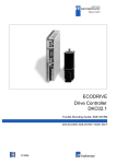
ECODRIVE
DKC01.1/DKC11.1 Drive Controllers
Functional Description: ASE 04VRS
DOK-ECODRV-ASE-04VRS**-FKB1-EN-P
275270
Indramat
ECODRIVE DKC01.1/DKC11.1 Drive Controllers
Title
Type of Documentation
Document Type Description
Internal Filing Notation
ECODRIVE DKC01 .1/ DKC11.1 Drive Controllers 04VRS
Functional Description
DOK-ECODRV-ASE-04VRS**-FKB1-EN-P
• Mappe 56-04V-EN Register 3
• 209 0073-4332-01
• Based on: 04V10
• DriveTop: 04V03
What is the purpose of this
documentation?
The following document describes the functions of the fimware FWAECODRV-ASE-04VRS-MS.
The document serves:
• to describe all of the functional characteristics.
• for parameterization of the drive controller.
• for data security of the drive parameter
• for error diagnosis and error removal
Change Notice
Copyright Mark
Document identification of previous Release
and current releases
Date
Remarks
DOK-ECODRV-ASE-04VRS**-FKB1-EN-P
First Release
07.97
INDRAMAT GmbH, 1997
Distibution as well as reproduction of this documentation, commercial use
or communication of its contents will not be permitted without expressed
written permission. Violation of these stipulations will require
compensation. All rights reserved for the issuance of the patent or
registered design. (DIN 34-1)
Validity
Published by
All rights are reserved with respect to the content of this documentation
and the availability of the product.
INDRAMAT GmbH • Bgm.-Dr.-Nebel-Str. 2 • D-97816 Lohr a. Main
Dept. END (MW/JR)
About this documentation
ECODRIVE DKC01.1/DKC11.1 Drive Controllers
Contents
1 System Overview
1-1
1.1 ECODRIVE - the Economical Control Drive for Automation ................................................................1-1
1.2 Ecodrive - a Family of Control Drives...................................................................................................1-1
1.3 Overview of DKC01.1/DKC11.1 Functions..........................................................................................1-2
DKC01.1 - Modes of Operation .....................................................................................................1-2
DKC01.1/DKC11.1 General Characteristics..................................................................................1-6
Functional Differences between DKC01.1 and DKC11.1..............................................................1-7
2 Safety Instructions for Electrical Drives
2-1
2.1 General.................................................................................................................................................2-1
2.2 Protection against contact with electrical parts ....................................................................................2-2
2.3 Protection by protective low voltage (PELV) against electrical shock............................................2-4
2.4 Protection against dangerous movements...........................................................................................2-5
2.5 Protection against magnetic and electromagnetic fields during operations and mounting ..................2-7
2.6 Protection during handling and installation...........................................................................................2-7
2.7 Battery safety........................................................................................................................................2-8
3 Preparing for Startup
3-1
3.1 General Instructions for Startup Procedure..........................................................................................3-1
3.2 Drive Top Startup Procedure and Diagnostics.....................................................................................3-1
3.3 DriveTop-System Requirements ..........................................................................................................3-1
3.4 Installation of DriveTop.........................................................................................................................3-2
Starting the Installation Program ...................................................................................................3-2
Setting communications parameters.............................................................................................3-3
3.5 Connecting the PCs with the Drive Controller ......................................................................................3-5
3.6 Minimal Installation for Operation of a DKC with DriveTop .................................................................. 3-6
3.7 DriveTop Start Up.................................................................................................................................3-7
Scanning for Connected Drives.....................................................................................................3-7
Online and Offline Operation .........................................................................................................3-8
Diagnostic Window........................................................................................................................3-9
Password protection ......................................................................................................................3-9
Integrating help sytems ...............................................................................................................3-12
3.8 DriveTop Menu Structure ...................................................................................................................3-13
3.8 ............................................................................................................................................................3-13
Files .............................................................................................................................................3-13
Parameter....................................................................................................................................3-13
Startup Procedure .......................................................................................................................3-15
Drive ............................................................................................................................................3-15
Options ........................................................................................................................................3-15
DOK-ECODRV-ASE-04VRS**-FKB1-EN-P • 07.97
Contents I
ECODRIVE DKC01.1/DKC11.1 Drive Controllers
Help .............................................................................................................................................3-15
3.9 Printing Parameter Data.....................................................................................................................3-16
4 Motor and Drive Controller Selection
4-1
4.1 General Information on Selecting a Motor and Drive Controller .........................................................4-1
4.2 Motor Selection ....................................................................................................................................4-2
4.3 Drive Controller Selection.....................................................................................................................4-2
Selecting the Overload Factor .......................................................................................................4-3
Selecting the PWM-Frequency......................................................................................................4-3
5 DKC01.1 Drive Controller with Integrated Positioning Control
5-1
5.1 Fundamental Method of Operation for Position Control....................................................................... 5-1
5.2 Setting operation mode: Position control with position interface ..........................................................5-1
Position control with following error ...............................................................................................5-2
Position control without following error ..........................................................................................5-2
Selecting the appropriate position control mode ...........................................................................5-2
5.3 Positioning Operation ...........................................................................................................................5-3
Absolute Positioning ......................................................................................................................5-3
Relative positioning block without save residual path ...................................................................5-4
Relative positioning block with residual path save ........................................................................5-6
Continuous Motion in Positive/Negative Direction.......................................................................5-14
5.4 Following block mode.........................................................................................................................5-15
General information on following block mode .............................................................................5-15
Selecting and activating a following block ...................................................................................5-15
Indexing in following block mode.................................................................................................5-15
Starting a following block sequence ............................................................................................ 5-21
Interrupting a following block sequence ......................................................................................5-21
Parametrization notes for following blocks ..................................................................................5-26
5.5 Positioning Command Input ...............................................................................................................5-29
Command Number ......................................................................................................................5-29
Positioning Command Data.........................................................................................................5-29
5.6 Choosing, Starting and Selecting a Positioning Command................................................................5-32
Choosing a Positioning Command ..............................................................................................5-32
Starting Positioning Commands .................................................................................................. 5-32
Interrupting Positioning Commands ............................................................................................5-32
Acknowledging position block select with drive enable active.....................................................5-32
Acknowledging drive enable off...................................................................................................5-35
Acknowledging control voltage interrupt......................................................................................5-35
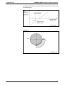
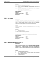
5.7 Target position processing with modulo weighting.............................................................................5-36
Modfulo function ..........................................................................................................................5-36
Modulo processing - marginal conditions ....................................................................................5-38
Modulo format processing of command values...........................................................................5-39
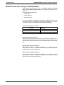
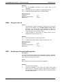
5.8 Positioning with limited speed ............................................................................................................5-40
Function.......................................................................................................................................5-40
Applictions ...................................................................................................................................5-40
Example.......................................................................................................................................5-41
Parameters..................................................................................................................................5-41
II
Contents
DOK-ECODRV-ASE-04VRS**-FKB1-EN-P • 07.97
ECODRIVE DKC01.1/DKC11.1 Drive Controllers
Activation .....................................................................................................................................5-41
5.9 Positioning interface connections.......................................................................................................5-42
6 DKC01.1 Drive Controller with Stepping Motor Interface
6-1
6.1 General Information on operations using a Stepping Motor Interface..................................................6-1
6.2 Setting Operation Mode: Position Control with Stepping Motor Interface ............................................6-1
Position Control with Following Error.............................................................................................6-2
Position Control Without Following Error....................................................................................... 6-2
Selecting the Appropriate Position Control Mode..........................................................................6-2
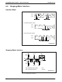
6.3 Stepping Motor Signal Processing .......................................................................................................6-3
6.4 Stepping Motor Interface ......................................................................................................................6-4
Interface Mode...............................................................................................................................6-4
Stepping Motor Interface ...............................................................................................................6-4
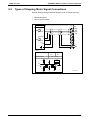
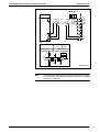
6.5 Types of Stepping Motor Signal Connections ......................................................................................6-5
7 DKC01.1 / DKC11.1 Drive Controller with Analog Speed Interface
7-1
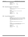
7.1 General Notes on operations with an Analog Speed Interface ............................................................7-1
7.2 Setting Mode: Speed Regulation with Analog Interface .......................................................................7-1
7.3 Analog Speed Command Value Processing ........................................................................................7-2
Command Value Scaling...............................................................................................................7-2
Offset Setting of the Analog Velocity Command Value .................................................................7-2
Command Value Smoothing .........................................................................................................7-3
Analog Interface ............................................................................................................................7-3
8 DKC01.1/DKC11.1 Drive Controller with Analog Torque Interface
8-1
8.1 General Instructions for Operation with Torque Interface ....................................................................8-1
8.2 Setting the Operating Mode: Torque Regulation with an Analog Command Value .............................8-2
8.3 Analog Torque Command Value Processing .......................................................................................8-3
Scaling the Analog Torque Command Value ................................................................................8-3
Adjusting the Offset of the Analog Torque Input ...........................................................................8-3
Analog Interface ............................................................................................................................8-4
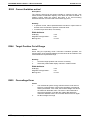
8.4 Velocity Supervision in Torque Regulation...........................................................................................8-4
9 DKC01.1/DKC11.1 with velocity and angle synchronization
9-1
9.1 Implementing an electronic gearbox ....................................................................................................9-1
9.2 Generating the master axis position.....................................................................................................9-2
9.3 Velocity synchronization .......................................................................................................................9-5
Setting operating mode: velocity synchronization, real master axis ..............................................9-5
The basic operating principle of velocity synchronization..............................................................9-6
Setting velocity synchronization parameters .................................................................................9-7
Synchronization with velocity synchronization ...............................................................................9-9
Check-back with speed synchronization .......................................................................................9-9
9.4 Angle synchronization ........................................................................................................................9-10
Setting anlg synchronization mode..............................................................................................9-10
Basic operating principle of angle synchronization......................................................................9-11
Setting angle synchronization parameters ..................................................................................9-12
Synchronization with angle synchronization ................................................................................9-12
DOK-ECODRV-ASE-04VRS**-FKB1-EN-P • 07.97
Contents III
ECODRIVE DKC01.1/DKC11.1 Drive Controllers
Check-back with angle synchronization ......................................................................................9-15
10 General Drive Functions
10-1
10.1 Scaling and Mechanical System Data..............................................................................................10-1
Linear Scaling..............................................................................................................................10-1
ROTARY SCALING.....................................................................................................................10-3
Processing Position Data ............................................................................................................10-4
10.2 Drive limits........................................................................................................................................10-5
Transverse range limits ...............................................................................................................10-5
Limiting Velocity...........................................................................................................................10-7
Torque Limits...............................................................................................................................10-7
10.3 Monitoring functions and error reactions..........................................................................................10-9
Monitoring functions ....................................................................................................................10-9
10.4 Error Handling ................................................................................................................................10-11
10.5 Automatic control loop settings ......................................................................................................10-13
General comments ....................................................................................................................10-13
Precondition for starting the automatic control loop setting.......................................................10-13
Dialog for the automatic control loop setting .............................................................................10-15
Chronological sequence of the automatic control loop setting ..................................................10-18
Results of the automatic control loop setting.............................................................................10-19
10.6 Manual control loop settings...........................................................................................................10-20
General Information for Selecting the Control Loop Settings ....................................................10-20
Loading Default Parameters......................................................................................................10-20
Executing the Basic LoadFunction After Changing the Motor or Drive Controller.....................10-20
Executing the Basic Load Feature as a Command in the "Control loop Setting" Dialog...........10-21
Setting the Current Regulator....................................................................................................10-21
Setting the Velocity Loop ...........................................................................................................10-22
10.7 Loop Monitoring..............................................................................................................................10-26
Velocity Loop Monitoring ...........................................................................................................10-26
Position Loop Monitoring ...........................................................................................................10-27
10.8 Status Message..............................................................................................................................10-28
Ready for Work (bb) ..................................................................................................................10-28
In Position (INPOS) ...................................................................................................................10-29
In Motion (INBWG) ....................................................................................................................10-31
In Reference (INREF)................................................................................................................10-32
Position Switch Point (WSP) .....................................................................................................10-32
Illustration of Status Output Connections ..................................................................................10-33
10.9 Actual Position Output....................................................................................................................10-33
Incremental Encoder Emulation ................................................................................................10-33
Absolute Encoder Emulation (SSI) ............................................................................................10-35
10.10 Drive controlled Homing Procedure .............................................................................................10-37
Homing When Using a Motor With Resolver Feedback (Standard)..........................................10-38
Homing When Using a Motor With Integrated Absolute Encoder Function (Optional) .............10-44
10.11 Jogging.........................................................................................................................................10-46
10.12 Feedrate Override Function .........................................................................................................10-48
10.13 Analog Output ..............................................................................................................................10-49
10.14 Motor Brake..................................................................................................................................10-50
IV
Contents
DOK-ECODRV-ASE-04VRS**-FKB1-EN-P • 07.97
ECODRIVE DKC01.1/DKC11.1 Drive Controllers
10.15 Activating the Drive ......................................................................................................................10-52
Controller Enable.......................................................................................................................10-52
Drive Stop / Start .......................................................................................................................10-53
11 Serial Communication
11-1
11.1 General Information for Serial Communication................................................................................11-1
11.2 Communication via the RS232 Interface..........................................................................................11-1
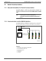
11.3 Communication over the RS485 Interface .......................................................................................11-2
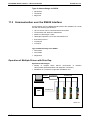
Operation of Multiple Drives with DriveTop .................................................................................11-2
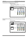
Parameterization and Diagnostics via a SPS (PLC)....................................................................11-3
Parameterization and Diagnostics for Drive Group through the Operator Interface ...................11-3
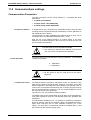
11.4 Communications settings .................................................................................................................11-4
Communication Parameters........................................................................................................11-4
Setting of the Drive Address........................................................................................................11-5
Original State after Establishing the Control Voltage ..................................................................11-5
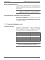
11.5 Communications procedure .............................................................................................................11-5
Parameter Structure ....................................................................................................................11-5
Communication with a Specific Unit on the Bus..........................................................................11-6
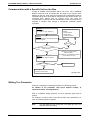
Writing To a Parameter ...............................................................................................................11-6
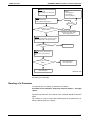
Reading of a Parameter ..............................................................................................................11-7
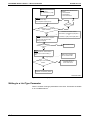
Writing to a List Type Parameter.................................................................................................11-8
Reading a List Type Parameter.................................................................................................11-11
Executing Parameter Commands .............................................................................................11-12
Requesting the Status of Commands........................................................................................11-14
Ending a Parameter Command.................................................................................................11-15
Error Message ...........................................................................................................................11-16
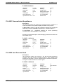
11.6 Operation Example.........................................................................................................................11-17
Changing of the Positioning Command Data ............................................................................11-17
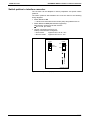
11.7 Connection techniques...................................................................................................................11-18
Application example RS 485 - communications with DriveTop .................................................11-18
Switch poition in interface converter.......................................................................................... 11-19
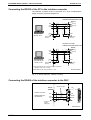
Connecting the RS232 of the PC to the interface converter .....................................................11-20
Connecting the RS485 of the interface converter to the DKC...................................................11-20
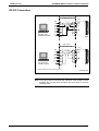
RS 232 Connection ...................................................................................................................11-21
12 Index
12-1
Supplement A: Parameter Description
Supplement B: Diagnostic Message Description
Customer Service Locations
DOK-ECODRV-ASE-04VRS**-FKB1-EN-P • 07.97
Contents V
ECODRIVE DKC01.1/DKC11.1 Drive Controllers
Notes
VI
Contents
DOK-ECODRV-ASE-04VRS**-FKB1-EN-P • 07.97
ECODRIVE DKC01.1/DKC11.1 Drive Controllers
1
System Overview
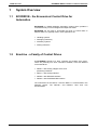
1.1
ECODRIVE - the Economical Control Drive for
Automation
ECODRIVE is a digital intelligent automation system which provides a
cost effective way to control single and multiple axis tasks.
ECODRIVE can be used to accomplish all kinds of control tasks in
different fields. It is typically used in such applications as:
• Handling systems
• Packaging machinery
• Assembly systems
• Printing machines
1.2
Ecodrive - a Family of Control Drives
An ECODRIVE consists of a drive controller and a MKD servo motor.
There are presently four drive controllers available, each with different
control interfaces.
• DKC01.1 with analog, stepper motor, and
positioning interfaces
• DKC11.1 with analog interface
• DKC02.1 with SERCOS interface
• DKC03.1 with PROFIBUS-DP interface
The instructions for the DKC01.1 and the DKC11.1 are described in the
following section. The DKC02.1 and DKC03.1 have their own
documentation.
DOK-ECODRV-ASE-04VRS**-FKB1-EN-P • 07.97
System Overview 1-1
ECODRIVE DKC01.1/DKC11.1 Drive Controllers
1.3
Overview of DKC01.1/DKC11.1 Functions
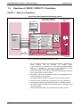
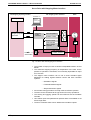
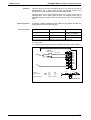
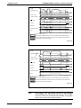
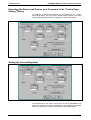
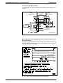
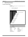
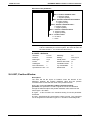
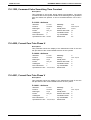
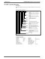
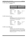
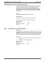
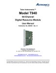
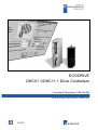
DKC01.1 - Modes of Operation
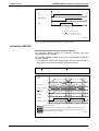
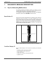
Servo Drive with Integrated Positioning Control
SPS Control
MS-DOS® - PC
Control drive DKC01.1
with position interface
AC servo motor
MKD
Parameter
Diagnostics
Operating data
RS 232
RS 485
Control drive processor
I/O Card
Selection
of
position
settings
Control inputs
Saved
position
settings
Control outputs
2° Position 1
21 Position 2
22 .
.
24 Position 32
Position
actual value
Fine interpolation
M
3~
Position control
Speed control
~
~
Field oriented
stator voltage
regulator
High resolution
position interface
FS0200d1.drw
Fig. 1-1: Servo drive with integrated positioning control
• Up to 32 position settings can be stored in the DKC01.1 and DKC11.1.
These
settings
can
be
selected
via
parallel
inputs.
If block selection is conducted via a serial interface (RS232/RS485),
then it is possible to use up to 64 positioning blocks.
The DKC01.1 executes position settings independently.
• The drive controller can conform to mechanical transmission elements
such as gear ratios or feed constants.
• All position, speed, and acceleration data can be weighted rotary or
linear depending on axial kinetics.
• An internal homing procedure can help create a reference position.
• The axis can be controlled via the jog function for set-up operations.
• The positioning speed can be influenced with the Feedrate Override.
• Limit switch inputs and parametrical position limits are available to set
travel range limits.
• The drive controller status can be determined via status outputs.
1-2
System Overview
DOK-ECODRV-ASE-04VRS**-FKB1-EN-P • 07.97
ECODRIVE DKC01.1/DKC11.1 Drive Controllers
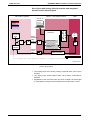
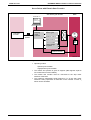
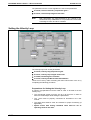
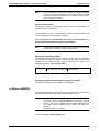
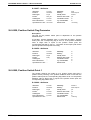
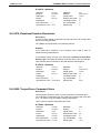
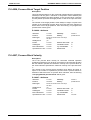
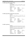
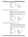
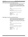
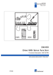
Servo Drive with Analog Velocity Interface and Integrated
Actual Position Value Register
Control
with position regulator
Control drive DKC01.1 or
DKC11.1 with analog interface
AC servo motor
MKD
MS-DOS® - PC
Parameter
Diagnosis
Operating data
Parameter
Diagnosis
Operating data
RS 232
Control drive
processor
Position
command
value
+W
Kv
-X
RS 485
D
Speed
command
value
A analog
+/- 10V
Position
interface
Position
actual
value
A
D
Speed control
Field oriented
stator voltage
regulator
M
3~
~~
High resolution
position interface
Linearmaßstab
FS0201d1.drw
Fig. 1-2:
Servo drive with analog velocity interface and integrated actual
position value register
• The scaling factor of the analog velocity command value can be set in
the DKC.
• The output of the actual position value can be either incremental or
absolute.
• Regardless of the command value, the drive controller can be brought
to a standstill via a logic input and kept drift free under active control.
DOK-ECODRV-ASE-04VRS**-FKB1-EN-P • 07.97
System Overview 1-3
ECODRIVE DKC01.1/DKC11.1 Drive Controllers
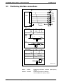
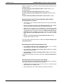
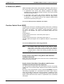
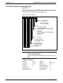
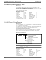
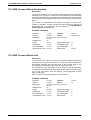
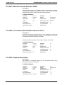
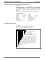
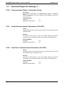
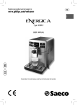
Servo Drive with Stepping Motor Interface
Control
with stepping impulse generator
Control drive DKC01.1
with stepping motor interface
AC servo motor
MKD
MS-DOS® - PC
Interpolation
Parameter
Diagnosis
Operating data
RS 232
RS 485
Control drive processor
Stepping impulse
generator
Stepping
motor
interface
Forwards
Backwards
Fine interpolation
M
3~
Position control
Speed control
Field oriented
stator voltage
regulator
Position
actual value
~~
High resolution
position interface
FS0202d1.drw
Fig. 1-3: Servo drive with stepping motor interface
• The number of steps per rotor revolution is adjustable between 16 and
65536.
• The maximum stepping frequency is independent of the load. As the
position of operation is monitored, it is technically impossible for steps
to be "left out".
• The stepper motor interface can be set to three standard signal
definitions for trading signals between control and drive controller
systems.
− Quadrature signals
− Forward/backward signals
− Step and direction signals
• An internal homing procedure can help create a reference position.
• The axis can be controlled via the jog function for set-up operations.
• The homing and jogging speeds can be influenced via the Feedrate
Override.
• Limit switch inputs and parametrical position limits are available to set
travel range limits.
• The drive controller status can be determined via status outputs.
1-4
System Overview
DOK-ECODRV-ASE-04VRS**-FKB1-EN-P • 07.97
ECODRIVE DKC01.1/DKC11.1 Drive Controllers
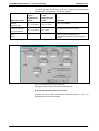
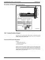
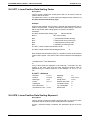
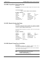
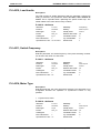
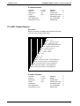
Servo Drives with Electric Gear Function
Control drive DKC01.1
with electric gear function
AC-servo motor
MKD
MS-DOS® - PC
Parameter
Diagnosis
Operating data
RS 232
RS 485
Control drive processor
Lead axis
encoder
Lead axis
position
Stepping
motor
interface
Electric gear
M
3~
Position control
Speed control
Field oriented
stator voltage
regulator
~~
High resolution
position interface
FS5002d1.drw
Fig. 1-4: Servo Drives with Electric Gear Function
• Operating modes:
Speed synchronization
Angle/phase synchronization
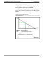
• The master axis position is given in degrees (360 degrees equal to
one master axis encoder rotation).
• The master axis encoder must be connected to the step motor
interface of the DKC.
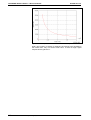
• The maximum permissible signal frequency fmax of the step motor
interface hereby represents a restriction of the number of lines ZI
which can be emulated.
DOK-ECODRV-ASE-04VRS**-FKB1-EN-P • 07.97
System Overview 1-5
ECODRIVE DKC01.1/DKC11.1 Drive Controllers
DKC01.1/DKC11.1 General Characteristics
Direct Power Supply Connection
The drive controller can be connected directly to single and three phase
230V power supplies or three phase power supplies ranging from 380V to
480V without transformers. A power rectifier, DC bus capacitor, and
bleeder are included as standard equipment.
Integrated Brake Activation
The optional brake in MKD motors is activated directly via the drive
controller.
Actual Position Value Measurement
ECODRIVE measures the actual position value via the motor feedback
system
• Incremental position measurement (standard)
The actual position value will be set at a random value when the power
supply is first turned on. To give the actual position value a fixed
reference point, the reference point must be set with a defined homing
procedure.
• Absolute position measurement (optional)
After the power supply has been turned on, the absolute actual
position value in relation to a fixed reference point is immediately
available. Thus, completing the homing procedure is unnecessary.
Actual Position Value Output
The DKC01.1 has an actual position value output for transmission of the
actual position value to an NC control. Actual position values can be
transmitted in either incremental or absolute format.
• Incremental Actual Position Value Output
5V-TTL incremental encoder signals with an adjustable counter are
given as an output. Incremental actual position value output is possible
with both actual position value and absolute actual position value
acquisition.
• Absolute Actual Position Value Output
The absolute actual position value is transmitted in the standard SSIformat for position encoders. The output of the absolute actual
position value is only possible when using a motor with an absolute
encoder (optional).
Integrated Diagnostic Display
All internal condition and error analysis is displayed via a dual position
seven segment display.
Easy Installation
The installation and diagnostic program DRIVETOP helps with a userfriendly installation via the serial RS-232 interface on a PC running
TM
3.1.
Windows
1-6
System Overview
DOK-ECODRV-ASE-04VRS**-FKB1-EN-P • 07.97
ECODRIVE DKC01.1/DKC11.1 Drive Controllers
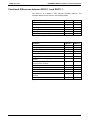
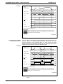
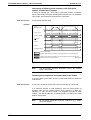
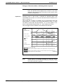
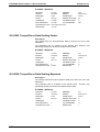
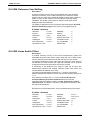
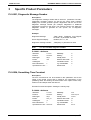
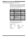
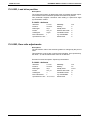
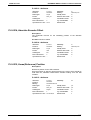
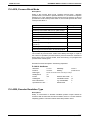
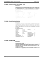
Functional Differences between DKC01.1 and DKC11.1
The DKC11.1 is a DKC01.1 with reduced operating features. The
essential differences are shown in the following tables.
Type of Operation
DKC01.1
Position control with position interface
X
Position control with stepping motor interface
X
Speed synchronization
X
Angle synchronization
X
Velocity control with analog interface
X
DKC11.1
X
Torque control with analog interface
X
X
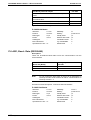
Fig. 1-5: Overview:Types of operation available with DKC01.1 / DKC11.1
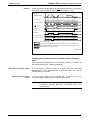
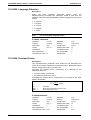
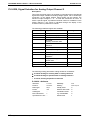
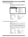
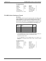
Function
DKC01.1
DKC11.1
Transversing range limits via limit switch
X
Position regulator loop monitoring
X
Status messages (INPOS, INBWG, INREF)
X
Positional forward break-over point function
X
Control drive guided homing
X
Jogging
X
Override function for jogging, positioning, and
homing
X
Actual position output
(Incremental or absolute)
X
X
Built-in error reaction
X
X
Velocity regulator loop monitoring
X
X
Analog diagnostic outputs
X
X
Built-in control of the motor brake
X
X
Drift-free standstill of the drive via the stop-drivefunction
X
X
Automatic control loop settings
X
Fig. 1-6: Overview:Functions available with the DKC01.1 / DKC11.1
DOK-ECODRV-ASE-04VRS**-FKB1-EN-P • 07.97
X
System Overview 1-7
ECODRIVE DKC01.1/DKC11.1 Drive Controllers
Notes
1-8
System Overview
DOK-ECODRV-ASE-04VRS**-FKB1-EN-P • 07.97
ECODRIVE DKC01.1/DKC11.1 Drive Controllers
2
Safety Instructions for Electrical Drives
2.1
General
These instructions must be read and understood before the equipment is
used to minimize the risk of personal injury and /or property damage.
Follow these safety instructions at all times.
Do not attempt to install, use or service this equipment without first
reading all documentation provided with the product. Please read and
understand these safety instructions, and all user documentation for the
equipment, prior to working with the equipment at any time. You must
contact your local Indramat representative if you cannot locate the user
documentation for your equipment. A listing of Indramat offices is
supplied in the back of this manual. Request that your representative
send this documentation immediately to the person or persons
responsible for the safe operation of this equipment.
If the product is resold, rented and/or otherwise transferred or passed on
to others, these safety instructions must accompany it.
WARNING
Improper use of this equipment, failure to follow the
attached safety instructions, or tampering with the
product, including disabling of safety device, may
result in personal injury, severe electrical shock,
death, or property damage!
INDRAMAT GmbH is not liable for damages resulting from failure to
observe the warnings given in these instructions.
• Operating, maintenance and safety instruction in the appropriate
language must be ordered and received before initial start-up, if the
instructions in the language provided are not understood perfectly.
• Proper and correct transport,storage, assembly, and installation as
well as care in operation and maintenance are prerequisites for
optimal and safe operation of this equipment.
• Trained and qualified personnel in electrical equipment:
Only trained and qualified personnel may work on this equipment or in
its vicinity. Personnel are qualified if they have sufficient knowledge of
the assembly, installation, and operation of the product as well as of all
warnings and precautionary measures noted in these instructions.
Furthermore, they should be trained, instructed, and qualified to switch
electrical circuits and equipment on and off, to ground them, and to
mark them according to the requirements of safe work practices and
common sense. They must have adequate safety equipment and be
trained in first aid.
• Use only spare parts approved by the manufacturer.
• All safety regulations and requirements for the specific application
must be followed as practiced in the country of use
• The equipment is designed for installation on commercial machinery.
• Start-up is only permitted once it is sure that the machine in which the
products are installed complies with the requirements of national
safety regulations and safety specifications of the application.
European countries: see Directive 89/392/EEC (Machine Guideline);
DOK-ECODRV-ASE-04VRS**-FKB1-EN-P • 07.97
Safety Instructions for Electrical Drives 2-1
ECODRIVE DKC01.1/DKC11.1 Drive Controllers
• Operation is only permitted if the national EMC regulations for the
application are met.
The instructions for installation in accordance with EMC requirements
can be found in the INDRAMAT document „EMC in Drive and Control
Systems“.
The machine builder is responsible for the adherence of the limiting
values as prescribed in the national regulations and specific
regulations for the application concerning EMC.
European countries: see Directive 89/336/EEC (EMC Guideline);
U.S.A.: See National Electrical Codes (NEC), National Electrical
Manufacturers Association (NEMA), and local building codes. The
user of this equipment must consult the above noted items at all times.
• Technical data, connections, and operational conditions are specified
in the product documentation and must be followed.
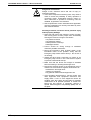
2.2
Protection against contact with electrical parts
Note: This section pertains to equipment and drive components with
voltages over 50 Volts.
Touching live parts with potentials of 50 Volts and higher applied to them
can be dangerous and cause severe electrical shock. In order for
electrical equipment to be operated, certain parts must have dangerous
voltages applied to them.
2-2
Safety Instructions for Electrical Drives
DOK-ECODRV-ASE-04VRS**-FKB1-EN-P • 07.97
ECODRIVE DKC01.1/DKC11.1 Drive Controllers
DANGER
High Voltage!
Danger to life, severe electrical shock and risk of injury!
⇒ Only those trained and qualified to work with or on
electrical equipment are permitted to operate,
maintain and/or repair this equipment.
⇒ Follow general construction and safety regulations
when working on electrical installations.
⇒ Before switching on power, the ground wire must be
permanently connected to all electrical units according
to the connection diagram.
⇒ At no time may electrical equipment be operated if the
ground wire is not permanently connected, even for
brief measurements or tests.
⇒ Before beginning any work, disconnect mains or the
voltage source from the equipment. Lock the
equipment against being switched on while work is
being performed.
⇒ Wait 5 minutes after switching off power to allow
capacitors to discharge before beginning work.
Measure the voltage on the capacitors before
beginning work to make sure that the equipment is
safe to touch.
⇒ Never touch the electrical connection points of a
component while power is turned on.
⇒ Before switching the equipment on covers and
guards provided with the equipment must be installed
to prevent contact with live parts. Before operating
cover and guard live parts properly so they cannot be
touched.
⇒ A leakage current protective device must not be used
for an AC drive! Indirect contact must be prevented by
other means, for example, by an overcurrent
protective device.
European countries: according to EN 50178/ 1994;
⇒ Electrical components with exposed live parts must be
installed in a control cabinet to prevent direct contact.
European countries: according to EN 50178/ 1994;
⇒ U.S.A: See National Electrical Codes (NEC), National
Electrical Manufacturers Association (NEMA), and
local building codes. The user of this equipment must
consult the above noted items at all times.
DOK-ECODRV-ASE-04VRS**-FKB1-EN-P • 07.97
Safety Instructions for Electrical Drives 2-3
ECODRIVE DKC01.1/DKC11.1 Drive Controllers
DANGER
2.3
High discharge current!
Danger to life, risk of severe electrical shock and risk of
injury!
⇒ All units and the motors must be connected to a
grounding point with the ground wire or must be
grounded themselves before switching on power.
⇒ The discharge current is greater than 3.5 mA. A
permanent connection to the supply system is
therefore required for all units.
European countries: according to EN 50178/1994,
section 5.3.2.3;
⇒ U.S.: See National Electrical Codes (NEC), National
Electrical Manufacturers Association (NEMA), and
local building codes. The user of this equipment
must consult the above noted items at all times.
⇒ The ground wire must always be connected before
start-up, even during the performance of tests.
Otherwise, high voltages may be present at the unit
housing, which can result in severe electrical shock
and personal injury.
Protection by protective low voltage (PELV) against
electrical shock
All connections and terminals with voltages ranging between 5 and 50
volts on INDRAMAT products are protective low voltages designed in
accordance with the following standards on contact safety:
• International: IEC 364-4-411.1.5
• European countries
section 5.2.8.1.
WARNING
2-4
Safety Instructions for Electrical Drives
within
the
EU:
see
EN
50178/1994,
High
electrical
voltages
due
to
incorrect
connections!
Danger to life and limb, severe electrical shock and/or
serious bodily injury!
⇒ Only that equipment or those electrical components
and cables may be connected to all terminals and
clamps with 0 to 50 volts if these are of the protective
low voltage type (PELV = Protective Extra Low
Voltage).
⇒ Only connect those voltages and electrical circuits that
are safely isolated. Safe isolation is achieved, for
example, with an isolating transformer, an
optoelectronic coupler or when battery-operated.
DOK-ECODRV-ASE-04VRS**-FKB1-EN-P • 07.97
ECODRIVE DKC01.1/DKC11.1 Drive Controllers
2.4
Protection against dangerous movements
Dangerous movements can be caused when units have bad interfaces or
motors are connected incorrectly.
There are various causes of dangerous movements:
• Improper or incorrect wiring or cable connections
• equipment is operated incorrectly
• probe parameters or encoder parameters are set incorrectly
• broken components
• errors in software or firmware
Dangerous movements can occur immediately after equipment is
switched on or even after an unspecified time of trouble-free operation.
Although the monitoring circuits in the drive components make improper
operation almost impossible, personnel safety requires that proper safety
precautions be taken to minimize the risk of electrical shock, personal
injury and/or property damage. This means that unexpected motion must
be anticipated since safety monitoring built into the equipment might be
defeated by incorrect wiring or other faults.
DOK-ECODRV-ASE-04VRS**-FKB1-EN-P • 07.97
Safety Instructions for Electrical Drives 2-5
ECODRIVE DKC01.1/DKC11.1 Drive Controllers
DANGER
Dangerous movements!
Danger to life, electrical shock and risk of injury or
equipment damage!
⇒ In the drive component monitoring units, every effort is
made to avoid the possibility of faulty operation in
connected drives. Unintended machine motion or
other malfunction is possible if monitoring units are
disabled, by-passed or not activated.
⇒ Safe requirements of each individual drive application
must be considered on a case-by-case basis by users
and machine builders.
Avoiding accidents, electrical shock, personal injury
and/or property damage:
⇒ Keep free and clear of the machine’s range of motion
and moving parts. Prevent people from accidentally
entering the machine’s range of movement:
- use protective fences
- use protective railings
- install protective coverings
- install light curtains
⇒ Fences should be strong enough to withstand
maximum possible momentum.
⇒ Mount the Emergency Stop (E-Stop) switch in the
immediate reach of the operator. Verify that the
Emergency Stop works before start-up. Do not use if
not working.
⇒ Isolate the drive power connection by means of an
Emergency Stop circuit or use a safe lock-out system
to prevent unintentional start-up.
⇒ Make sure that the drives are brought to standstill
before accessing or entering the danger zone.
⇒ Disconnect electrical power to the equipment using a
master lock-out and secure against reconnection for:
- maintenance and repair work
- cleaning of equipment
- long periods of discontinued equipment use
⇒ Avoid operating high-frequency, remote control, and
radio equipment near equipment electronics and
supply leads. If use of such equipment cannot be
avoided, verify the system and the plant for possible
malfunctions at all possible positions of normal use
before the first start-up. If necessary, perform a
special Electromagnetic Compatibility (EMC) test on
the plant.
2-6
Safety Instructions for Electrical Drives
DOK-ECODRV-ASE-04VRS**-FKB1-EN-P • 07.97
ECODRIVE DKC01.1/DKC11.1 Drive Controllers
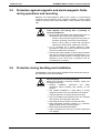
2.5
Protection against magnetic and electromagnetic fields
during operations and mounting
Magnetic and electromagnetic fields in the vicinity of current-carrying
conductors and permanent motor magnets represent a serious health
hazard to persons with heart pacemakers, metal implants and hearing
aids.
WARNING
2.6
Health hazard for persons with heart pacemakers,
metal implants and hearing aids in proximity to
electrical equipment!
⇒ Persons with pacemakers and metal implants are not
permitted to have access to the following areas:
− Areas in which electrical equipment and parts are
mounted, operating or are being commissioned.
− Areas in which parts of motors with permanent
magnets are being stored, repaired or mounted.
⇒ If it is necessary for a person wearing a heart
pacemaker to enter into such an area then a physician
must be consulted prior to doing so.
⇒ Persons with metal implants or hearing aids must take
care prior to entering into areas described above. It is
assumed that metal implants or hearing aids will be
affected by such areas and a physician must be
consulted prior to doing so.
Protection during handling and installation
All INDRAMAT products should be handled and assembled according to
the instructions in the documentation.
CAUTION
DOK-ECODRV-ASE-04VRS**-FKB1-EN-P • 07.97
Risk of injury due to incorrect handling!
Bodily injury caused by crushing, shearing, cutting, and
thrusting movements!
⇒ Observe
installation
instructions
and
safety
regulations before handling and working on the
product.
⇒ Use suitable installation in using lifting or moving
equipment. Refer to the user manual for the product.
⇒ Take precautions to avoid pinching and crushing.
⇒ Only use suitable tools specified in the user manuals
and use them according the instructions.
⇒ Use lifting devices and tools correctly and safely.
⇒ Wear appropriate protective clothing, e.g., protective
goggles, safety shoes, protective gloves.
⇒ Never stand under suspended loads.
⇒ Clean up liquids form the floor to prevent personnel
from slipping.
Safety Instructions for Electrical Drives 2-7
ECODRIVE DKC01.1/DKC11.1 Drive Controllers
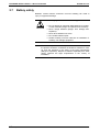
2.7
Battery safety
Batteries contain reactive chemicals. Incorrect handling can result in
injury or equipment damage.
Risk of injury due to incorrect handling!
CAUTION
⇒ Do not attempt to reactivate dead batteries by heating
or other methods (danger of explosion and corrosion).
⇒ Never charge batteries (danger from leakage and
explosion).
⇒ Never throw batteries into a fire.
⇒ Do not take batteries apart.
⇒ Handle carefully. Incorrect extraction or installation of
a battery can damage equipment.
Note: Environmental protection and disposal! The batteries contained in
the product should be considered as hazardous material for land,
air, and sea transport in the sense of the legal requirements
(Danger of explosion). Dispose of batteries separately from other
refuse. Observe the legal requirements in the country of
installation.
2-8
Safety Instructions for Electrical Drives
DOK-ECODRV-ASE-04VRS**-FKB1-EN-P • 07.97
ECODRIVE DKC01.1/DKC11.1 Drive Controllers
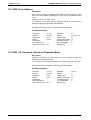
3
Preparing for Startup
3.1
General Instructions for Startup Procedure
In this chapter the initial operation and diagnostic system DriveTop will be
introduced. In general, it is necessary to install DriveTop on the PC if the
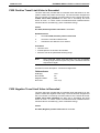
startup procedure of the DKC is to work. Drive Top follows this handbook
to concurrently run offline. In the following chapters the document will
frequently refer to this program.
Note:
3.2
If you would like to see a short summary of ECODRIVE's
qualities, go to section 9.
Drive Top Startup Procedure and Diagnostics
DriveTop is a WINDOWS based application program used in the initial
operation and diagnosis of ECODRIVE drive controllers.
DriveTop has a user friendly start up guide. The initial operator will be led
through a series of functional dialogues for the input of all operational
settings. For each of these dialogues there are help instructions that can
be activated with the press of a key.
The startup parameterization process is set up so that the user is only
confronted with parameter settings that are relevant to the chosen
operating configuration only.
3.3
DriveTop-System Requirements
DriveTop is a Windows based application program. Minimum PC
requirements are:
• IBM compatible 80386 / 40MHz (80486 recommended)
• 4MB RAM (8MB recommended)
• 5MB free hard drive space for Drive Top and an additional 15 MB for
the ECODRIVE help system
• A free serial port
• VGA graphics
• Mouse or compatable pointing instrument
• Windows 3.1 / 3.11 / Windows 95
DOK-ECODRV-ASE-04VRS**-FKB1-EN-P • 07.97
Preparing for Startup 3-1
ECODRIVE DKC01.1/DKC11.1 Drive Controllers
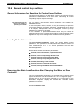
3.4
Installation of DriveTop
DriveTop will be on two (2) 3.5" disks (Dos format;1,44MB)
Note:
Please make a backup copy of the Drive Top installation
diskettes. Install the software from these copies. Store the
original diskettes in a safe place! For installation on your
computer, use the installation programs on the diskettes. It
will not work if you simply copy the diskettes.
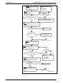
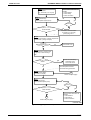
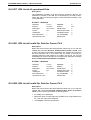
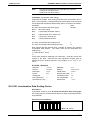
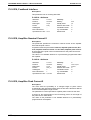
Starting the Installation Program
When installing DriveTop, procede as follows:
Installation in Windows 3.1 / 3.11
• Turn on the PC and start Windows
• Place “Diskette 1” in the disk drive
• Activate the Windows Program Manager
• At the menu, click on “FILE“ and choose from the drop down menu
“LOAD“.
• At the command prompt type "A:\SETUP” (if the DriveTop diskette is in
drive A:)
• The order of the installation program is as follows:
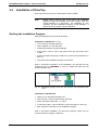
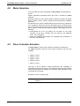
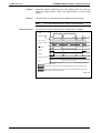
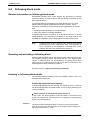
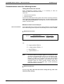
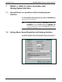
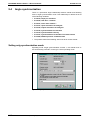
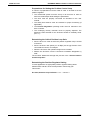
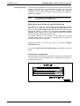
After a successful completion of the installation you will find the new
program group icon INDRAMAT on your PC. Within this group you will
find the DriveTop icon.
Fig. 3-1: INDRAMAT program group with the DriveTop and ECODRIVE Help
icons
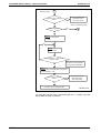
Installation in Windows 95
• switch PC on and startup Windows 95
• DriveTop disk 1 must be inserted into disk drive
• select command „EXECUTE...“ in menu
• in input field „Open:“ input A:\SETUP. (if DriveTop disk is in drive A:.)
• Now, follow the instructions of the installation program.
With a successful installation, the DriveTop program symbol can be
reached via Start / Program / Indramat.
3-2
Preparing for Startup
DOK-ECODRV-ASE-04VRS**-FKB1-EN-P • 07.97
ECODRIVE DKC01.1/DKC11.1 Drive Controllers
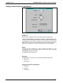
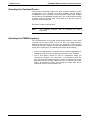
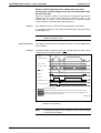
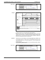
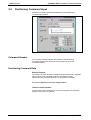
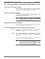
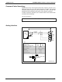
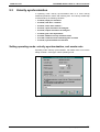
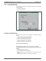
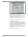
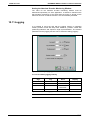
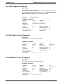
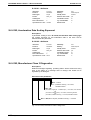
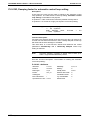
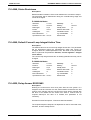
Setting communications parameters
Fig. 3-2: Communications dialog
COM-Port
Most PCs are equipped with several serial interfaces (COM ports).
Via the COM port setting it is possible to select the interface which is to be
used for communications with the drive controller. COM1 and COM2 can
be standardly set. (If COM3 or COM4 are to be used, then the pertinent
data must be entered in STOP.INI-File so that the interrupt and the I/O
addresses can be used. These two interfaces are then also available.
Mode
DriveTop can be connected to a drive controller via RS232 or it can
communicate with a drive group made up of 32 drives via an external
RS232/RS485 interface converter.
The desired mode must be set.
Baudrate
The DKC drive controller can communicate at different baud rates:
• 9600 baud
• 19200 baud
Additional interface parameters
• 8 data bits
• no parity
• one stop bit
DOK-ECODRV-ASE-04VRS**-FKB1-EN-P • 07.97
Preparing for Startup 3-3
ECODRIVE DKC01.1/DKC11.1 Drive Controllers
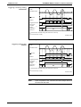
Response delay
The response delay defines the minimum length of time that must pass
after the last telegram symbol has been received via the serial interface
and before the first symbol of the reaction may be sent by the drive. This
length of time is required when operating the RS485 when changing from
transmit to receive mode or vice versa. This parameter is not needed
when operating the RS232. It should, nonetheless, be set at 1ms.
Depending on the PC used, it may be necessary to set the response
delay to 20 to 30 ms because of the higher priority interrupts in the PC
interrupt serial communications.
Addressing method
If several axes are to be connected to a shared master (PC or PLC) via
the RS485 interface, then each bus participant must have its own
individual address.
When setting the address via software, the address is fixed by inputting
an address number into input field drive address.
3-4
Preparing for Startup
DOK-ECODRV-ASE-04VRS**-FKB1-EN-P • 07.97
ECODRIVE DKC01.1/DKC11.1 Drive Controllers
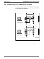
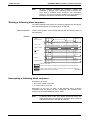
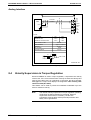
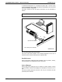
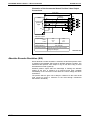
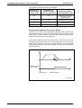
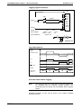
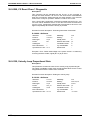
3.5
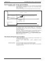
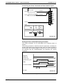
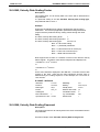
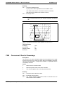
Connecting the PCs with the Drive Controller
A serial communication cable is used for data transfer between the PC
and the drive controller. This cable can be purchased from INDRAMAT
and can be either a 9 pin or 25 pin D-SUB connector. The pin diagram of
the cable is shown in the following Fig..
See also section 11.3 Communication over the RS485 Interface
max. 15 m
Cable: IKS 101
X1
PC with 9-pin
D-SUB connector
RxD
2
1
TxD
3
2
GND
DTR
5
3
DSR
6
6
RTS
CTS
7
5
8
4
RxD
TxD
0V
4
1)
DKC
max. 15 m
Cable: IKS 102
1
2
2
GND
DTR
7
3
DSR
6
6
RTS
CTS
4
5
5
4
RxD
TxD
PC with 25-pin
D-SUB connector
X1
3
RxD
TxD
0V
20
1)
DKC
1) Set the external screen on top of the device
AP0224d1.drw
Fig. 3-3: Connecting a PC via the RS232-interface on the DKC
Note:
Please pay close attention when connecting the relative
potential (OV/GND) to the internal cable shields!
DOK-ECODRV-ASE-04VRS**-FKB1-EN-P • 07.97
Preparing for Startup 3-5
ECODRIVE DKC01.1/DKC11.1 Drive Controllers
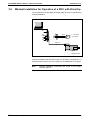
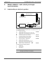
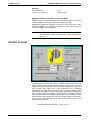
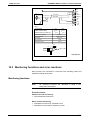
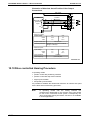
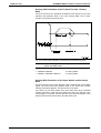
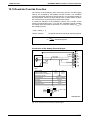
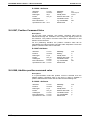
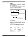
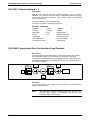
3.6
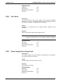
Minimal Installation for Operation of a DKC with DriveTop
The command for the first DKC parameter setup is shown in the following
minimal installation.
MS-Dos® - PC
X1
X4
X5
X6
1
4
+24 V
=
0V
~~
1 x AC 230V
50...60 Hz
X7
IKS 374
IKL...
MKD
FP0021d1.drw
Fig. 3-4: Minimal installation for simple parameter setups
With this installation the parameter setup can be easily accomplished. To
activate the drive and to carry out motions more installations are required.
Note:
3-6
Preparing for Startup
Detailed installation instructions are found in the Project
Planning Manual.
DOK-ECODRV-ASE-04VRS**-FKB1-EN-P • 07.97
ECODRIVE DKC01.1/DKC11.1 Drive Controllers
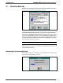
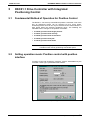
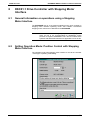
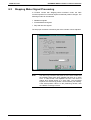
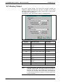
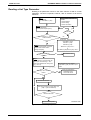
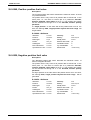
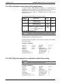
3.7
DriveTop Start Up
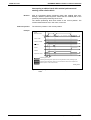
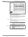
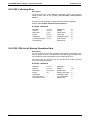
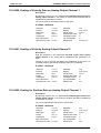
DriveTop can be started by double clicking the DriveTop icon. It then asks
as to how it should search the interfaces for drives.
Fig. 3-5: Inputting the baudrate for searching for drives
If a permanent baud rate is entered, then all drives at the serial interface
will be set to this baud rate, followed by a search for existing addresses.
AUTOBAUD = automatic baud rate search means that there is a search
for the first existing address (drive) at any available rate. All other drives
are set to the baud rate of the first drive located. If the RS-485 bus system
is used, then identical addresses should not be allowed to occur as this
could otherwise lead to bus collisions.
Note:
An automatic baud rate search takes more time.
Offline operations permits the preparation of parameter blocks without a
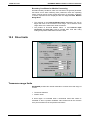
connected drive controller.
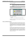
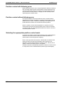
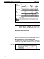
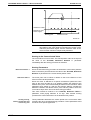
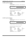
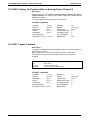
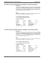
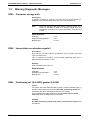
Scanning for Connected Drives
After DriveTop starts up, it searches for connected drives. It thereby tests
every drive address between 1 and 99.
Fig. 3-6: Scanning drive addresses
DOK-ECODRV-ASE-04VRS**-FKB1-EN-P • 07.97
Preparing for Startup 3-7
ECODRIVE DKC01.1/DKC11.1 Drive Controllers
If one or more drive controllers are found, then the parameter settings of
the drive will be classified.
Note:
Multiple drives may be found when the PC is connected by an
RS232/RS485-interface converter to more drives which are
interfaced with an RS485. All drives must be set to the same
baud rate.
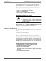
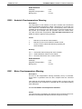
If no drive is found then the following dialogue appears:
Fig. 3-7: Dialogue appearing after failed scan
Reasons for this error can be:
• The +24Vdc control voltage for the DKC is not turned on or not
connected.
• Problem in the connection between PC and the drive controller.
Establishing a connection can be retried, the program can be cancelled or
you can go to offline mode.
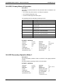
Online and Offline Operation
Parameter Setup through Online Operation Startup Procedure
Online operation is a drive controller in direct communication with the PC
via the serial communication link. That means that in online operation, all
the parameters that are in the current dialog screen of the start up
sequence are written directly to the drive controller and immediately
become effective. The user can also immediately test the results of his
installation.
Parameter Setup through Offline Operation Startup Procedure
Offline operation means there is no connection to the drive controller from
the PC. Offline operation allows the operator a conventient preparation of
the parameter settings which can then, in their entirety, be sent via a
connection to the desired drive controller. There remains but a little bit of
work for the operator which cannot be completed offline due to the
dependency of the machine.
3-8
Preparing for Startup
DOK-ECODRV-ASE-04VRS**-FKB1-EN-P • 07.97
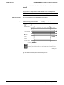
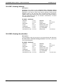
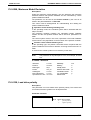
ECODRIVE DKC01.1/DKC11.1 Drive Controllers
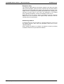
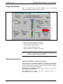
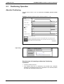
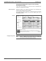
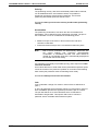
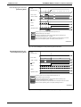
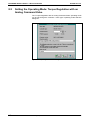
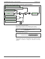
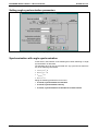
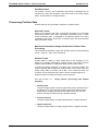
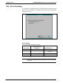
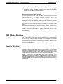
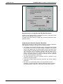
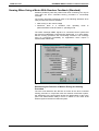
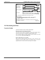
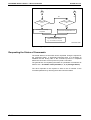
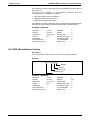
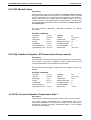
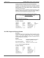
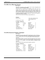
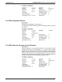
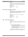
Diagnostic Window
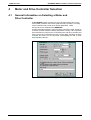
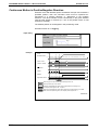
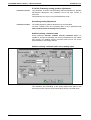
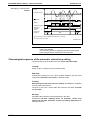
After a successful drive controller parameter scan, the following
diagnostic window will appear on the PC screen.
Fig. 3-8: Diagnostic Window
The diagnostic window displays the following:
• Drive controller status and error messages
• Command value and actual value
• Power on status and status signals
• Model descriptions of installed components
Note:
The diagnostic window appears only online. In offline
operation, graphics with the ECODRIVE components are
shown instead of the diagnostic window.
Password protection
General information on password protection
With the help of a user-defined password, accessing drive parameters
can be prevented. It is now not possible to make any parameter changes
until the user unlocks the drive by inputting the password. The password
protection itself is integrated into the drive.
The functions for password protection can be called up via the menu
Options/password protection.
The password '007' is preset in the drive. It unlocks the drive, i.e.,
password protection is not active.
DOK-ECODRV-ASE-04VRS**-FKB1-EN-P • 07.97
Preparing for Startup 3-9
ECODRIVE DKC01.1/DKC11.1 Drive Controllers
A user password can entail the letters A through Z / a - z (lower and upper
case letters must be differentiated!) and the numbers 0-9. There must be
a minimum of three symbols with a maximum of ten.
See also parameter S-0-0267, Password
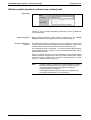
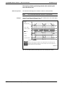
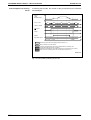
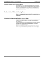
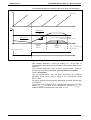
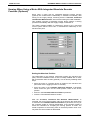
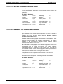
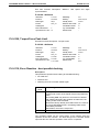
Change password
This dialog can be used to change the existing password, or to write '007'
back into the drive. The dialog can be called up with the menu
Options/Password protection/Change password.
Fig. 3-9: Dialog to change the password
Procedure: To enter a new password, all three editing fields must be
filled out. The current password must be entered into the first field (either
'007' or an already existent user password). The new password is entered
into the other two fields. A mouse or the tab key can be used for moving
from one field to the next. If the dialog is closed with the 'OK' key, and the
other entered passwords are correct, then the new password is active and
the drive locked.
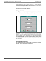
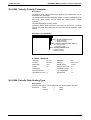
Cancel password protection
If a user password is to be cancelled and the drive permanently unlocked,
then '007' must be entered as the new password.
3-10
Preparing for Startup
DOK-ECODRV-ASE-04VRS**-FKB1-EN-P • 07.97
ECODRIVE DKC01.1/DKC11.1 Drive Controllers
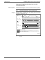
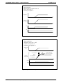
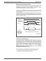
Unlock drive
If a parameter is to be changed (with password protection active), or if
select menu item Options/Password protection/Unlock drive is
selected, then this dialog appears.
Fig. 3-10: Unlock drive
Procedure: Enter the current user password and complete the dialog
using the 'OK' key. The drive is unlocked.
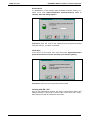
Lock drive
If the drive is to be locked, then using menu item Options/Password
protection/lock drive must be called up in the following dialog.
Fig. 3-11: Locking the drive
Procedure: Press the 'OK' key and the drive is locked.
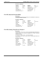
Locking with RS - 485
Once a user password is entered, the drive is locked when starting and
leaving DriveTop. If DriveTop is used to start a new drive ( RS - 485 ),
then both the old and the new drives are locked.
DOK-ECODRV-ASE-04VRS**-FKB1-EN-P • 07.97
Preparing for Startup 3-11
ECODRIVE DKC01.1/DKC11.1 Drive Controllers
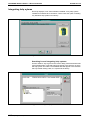
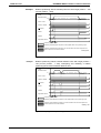
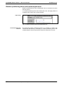
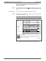
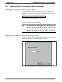
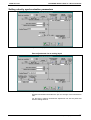
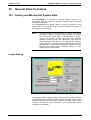
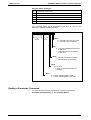
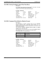
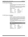
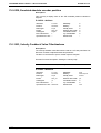
Integrating help sytems
DriveTop displays, in list "Documentation installed“ every help system
installed for Indramat drive controllers. There is also the option of adding
any Windows help system in this library.
Fig. 3-12: Documentation
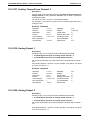
Searching for and integrating help systems
Use the "Search" key to get into the "Insert" dialog. Select the desired file
type (Indramat help or general help) and change to the directory in which
the help system is located. The available titles will appear in the selection
lists. By double clicking a title, it is copied into the library.
Fig. 3-13: Inserting a help system
3-12
Preparing for Startup
DOK-ECODRV-ASE-04VRS**-FKB1-EN-P • 07.97
ECODRIVE DKC01.1/DKC11.1 Drive Controllers
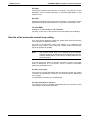
Deleting help systems from the documentation libary
Entries no longer wanted n the list of installed documentation can be
removed. Select the entry. Pressing key "Delete entry" will remove the
documentation from the list.
Opening a help system
Select an entry from the list of installed documentation. By double
clicking or pressing the key "Open", the Windows help system will be
started.
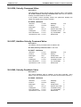
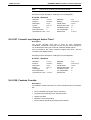
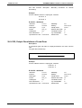
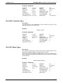
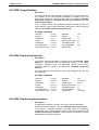
3.8
DriveTop Menu Structure
Files
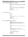
Load File
You can choose from a list of available parameter files. The data within
these parameter files can be loaded into the drive controller.
Note:
Load base parameters
In offline operation the content of the parameter files can be
viewed and changed.
The parameters are set to standards values at the factory. This overwrites
the present settings.
Parametrization mode is switched into.
Save File
The actual parameters of a connected drive controller are stored in a
parameter file on the PC.
Note:
"DKC11.PAR". With the help of this parameter file, you can
restore the state of the parameters of the drive controller at
any time. For your own parameter data, you should use other
file names.
Exit (Alt+F4)
Under the Menu item "End" you can leave the DriveTop program.
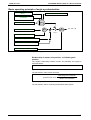
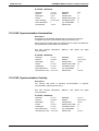
Parameter
Mode
The drive controller recognizes parameter mode and drive mode. Under
this menu one can switch between the modes. There are a number of
parameters that can only be altered in parametrization mode (7-segment
display P2). Traversing is only possible in operating mode.
DOK-ECODRV-ASE-04VRS**-FKB1-EN-P • 07.97
Preparing for Startup 3-13
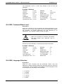
ECODRIVE DKC01.1/DKC11.1 Drive Controllers
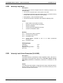
Controller / Motor type /
Selecting operating mode
Information about the connected motor type and the drive controller used
can be accessed via this menu point. This information is permanently
programmed into the motor feedback or drive controller. The user must
enter this data directly himself when Offline.
Additionally, the overload factor and PWM frequency with which the
drive is to be operated is entered here.
The desired operating mode can also be selected from a specific list.
Additional Parameter Displays
Additional parameter windows appear in the parameter menu. They are
independent of the selected operation. The mentioned parameter
windows are self-explanatory and will not be discussed further.
List of All Parameters
A list of all drive controller parameters can be examined and changed in
this menu. Therefore, a “Low-Level" possibility is required for parameter
examination. It is used in certain exceptional cases. Normally all the drive
parameters relating to start up parametrization were implemented.
List of the Invalid Parameters
By switching from parameter into drive mode, the actual parameters will
be checked for validity. All of the incorrect parameters and those that will
lead to boundary value problems are placed in an invalid parameter list
and can be corrected within the list.
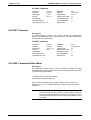
Scanning
As DriveTop is started, all the parameter information is read from the
connected drive controller. For reasons of speed, the specific parameter
values are only read from the contents of the parameters.
Often it is necessary to move from one drive controller to another without
restarting the DriveTop program. In order to refresh the parameter
window, it is necessary to perform a new parameter scan after plugging
the interface cable into another drive controller.
3-14
Preparing for Startup
DOK-ECODRV-ASE-04VRS**-FKB1-EN-P • 07.97
ECODRIVE DKC01.1/DKC11.1 Drive Controllers
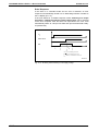
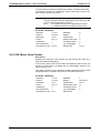
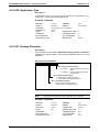
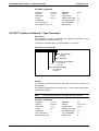
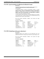
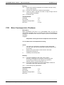
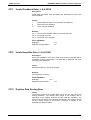
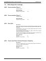
Startup Procedure
Parameter Settings
The parameters regarding the set up procedure leads the user through a
series of dialogue procedures. At the end, all of the necessary installation
requirements are set.
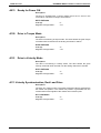
Drive
Scan
DriveTop can be physically connected to more that one drive controller at
the same time with the use of an RS232/RS485 interface converter.
Under the menu “Scanning", DriveTop looks for connected drives.
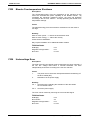
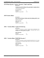
Select
If DriveTop is connected to more than one drive with the RS485
interface.Drive controller selection of
which device is being
communicated to is done from this menu.
Offline
DriveTop can be operated online or offline
Options
Language
Password protection
The language in which DriveTop functions and the language of the
parameters and diagnostics of the drive controller can be selected or
changed with this menu.
It is possible here
• to enter one's own password,
• lock the drive against unwanted parameter changes,
• and unlock the drive for parameter changes.
Communications
In communications, settings can be made that affect data exchange
between drive controller and PC.
• select the COM ports
• fixing the baud rate
• setting addresses
Help
Contents
Using Help
Documentation
Information about ...
This menu accesses the online documentation. The online documentation
contains a large scope of information regarding the functional qualities of
the drive system, parameter descriptions, and diagnostic descriptions.
There are on-screen general instructions to navigate through the help
system.
Help systems are integrated into the library.
Information regarding the software version of DriveTop.
DOK-ECODRV-ASE-04VRS**-FKB1-EN-P • 07.97
Preparing for Startup 3-15
ECODRIVE DKC01.1/DKC11.1 Drive Controllers
3.9
Printing Parameter Data
DriveTop does not offer a direct possibility of printing the parameter files.
Parameter files are stored as ASCII files and can be viewed with almost
any editor and printed. If parameter files are to be printed, it is suggested
that the Microsoft editor "Notepad" be used. Notepad is a part of
Windows 3.1 and therefore available within Windows 3.1. To print a
parameter file the following instructions are required:
An example of a parameter file "X_Axis.par”:
• Under the Program Manager menu choose "Run - File..."
• At the command prompt type "Notepad X_Axis.par" and click the "OK
icon."
• Click on menu item “File” then click on “Print”(The printing process will
begin.)
3-16
Preparing for Startup
DOK-ECODRV-ASE-04VRS**-FKB1-EN-P • 07.97
ECODRIVE DKC01.1/DKC11.1 Drive Controllers
4
Motor and Drive Controller Selection
4.1
General Information on Selecting a Motor and
Drive Controller
An ECODRIVE system consists of a drive controller (DKC) and a servo
motor (MKD). Selection documents (selection lists) can help in choosing
a drive controller and a motor for a specific application. These
documents can be obtained from INDRAMAT.
Certain information about the motor and drive controller is used at start up
to answer questions about installing parameters. During online operation
this information is read from the connected motor and drive controller and
does not have to be entered by the user. During offline operation the drive
controller and motor are not connected, necessitating the user to enter
this information directly.
Fig. 4-1:
DOK-ECODRV-ASE-04VRS**-FKB1-EN-P • 07.97
Dialog controller / motor type / select operating mode
Motor and Drive Controller Selection 4-1
ECODRIVE DKC01.1/DKC11.1 Drive Controllers
4.2
Motor Selection
The connected drive type is displayed in online mode. See parameter S0-0141.
Specific application information about the motor is needed for offline
operation.
DriveTop needs this motor-specific data to determine specific parameter
settings. (Motor current, velocity, standard control parameters, feedback
type, etc.)
If a different motor type is entered offline than is later used, the diagnosis
"UL" will appear at the time when the parameter block is loaded into the
drive. This means that the type of motor in the parameters is not identical
with the type of motor that is actually connected. If this happens, do the
following:
⇒ Acknowledge the error by pushing the S1-button on the drive
controller. If the drive controller does not discover any additional
errors, "bb" is displayed.
⇒ Reset the installation parameters and recalculate the parameters of
the drive controller limits.
4.3
Drive Controller Selection
In online mode, the type of the controller connected is entered here.
For offline operation, select the type of drive controller. There are five
available:
• DKC01.1-040-3
• DKC01.1-040-7
• DKC03.1-040-7
• DKC03.2-100-7
• DKC11.1-040-7
The type of drive controller selected determines the availability of
operational and functional modes. This adjustment happens automatically
during online operation by reading the "Controller Type" parameter of the
connected drive controller.
See also S-0-0140, controller type
Note:
4-2
Motor and Drive Controller Selection
The DKC11.1 limits the available functions only during online
operation.
DOK-ECODRV-ASE-04VRS**-FKB1-EN-P • 07.97
ECODRIVE DKC01.1/DKC11.1 Drive Controllers
Selecting the Overload Factor
The short term operating torque of the drive controller is defined via the
overload factor. The velocities and torques available with the different
combinations of drive controller, motors and power supply input voltages
are provided in the DKC/MKD selection lists. The overload factor needed
to obtain the drive controller data can be read off of the last column in
each line of the selection list.
See also P-0-0006, overload factor
Note:
The projected selection data is necessary for correct
adjustment.
Selecting the PWM-Frequency
The clock frequency of the power output (PWM frequency) of the drive
controller can be set to either 4 kHz or 8 kHz. The PWM frequency
determines the noise level of the motor, the permanent current carrying
capacity of the drive controller, and also the available short term operating
torque of the control drive. The following rules apply to the settings:
• The 4 kHz PWM frequency should be used in standard applications to
maintain the high short term operating torque of the drive controller.
• The 8 kHz setting should be used in applications where the
environment requires a low noise level. It is important to note that
when using the 8 kHz PWM frequency, the drive controller has a lower
permanent current carrying capacity as well as reduced short term
torque. All permanent current and permanent torque data will be
reduced by a factor of approximately 0.9.
DOK-ECODRV-ASE-04VRS**-FKB1-EN-P • 07.97
Motor and Drive Controller Selection 4-3
ECODRIVE DKC01.1/DKC11.1 Drive Controllers
Notes
4-4
Motor and Drive Controller Selection
DOK-ECODRV-ASE-04VRS**-FKB1-EN-P • 07.97
ECODRIVE DKC01.1/DKC11.1 Drive Controllers
5
DKC01.1 Drive Controller with Integrated
Positioning Control
5.1
Fundamental Method of Operation for Position Control
The DKC01.1 can store up to 64 different position commands. One of the
first 32 positioning blocks can be selected via five circuit inputs.
Positioning blocks 32 to 63 can only be selected via the serial interface. A
start signal starts the selected positioning block. The following are
allowable motion changes to the position commands:
• P-0-4006, process block target position
• P-0-4007, process block velocity
• P-0-4008, process block acceleration
• P-0-4009, process block jerk
• P-0-4019, process block mode
Note:
5.2
The positioning speed can be changed with the velocity
override function and by positioning with limited speed.
Setting operation mode: Position control with position
interface
"Position Control with Positioning Interface" mode is standardized by the
controller / motor type / operational mode window.
Fig. 5-1:
DOK-ECODRV-ASE-04VRS**-FKB1-EN-P • 07.97
Position control with positioning interface
DKC01.1 Drive Controller with Integrated Positioning Control 5-1
ECODRIVE DKC01.1/DKC11.1 Drive Controllers
Position control with following error
When positioning in this mode, a speed-dependent difference between
the command position and the actual position results (following error).
The time relationship between positioning processes depends on the
fixed Kv factor and may cause a "creeping" into the desired position,
especially with a small Kv factor.
Position control without following error
An expected speed control will position the drive controller without
following error, thereby causing the command position and the actual
position to be the same. Therefore, positioning is not dependent on a
speed difference between the command and actual position.
When in position control without lag distance, a speed pre-control
ensures that command and actual position are the same at constant
command speed. No speed-dependent difference between command
and actual position results.
Selecting the appropriate position control mode
In general, the position control without following error is advantageous
because in this mode the drive reaches its desired position the
quickest.(No Kv-factor-dependent creeping)
Given a less rigid mechanical system, undesireable acceleration kink
points as well as the mechanical vibrations are loosened. If the
application permits disadvantageous following errors, then the use of
position control with following error is suggested.
Vibrations will then be dampened through the reduction in the Kv factor.
A compromise is thus created between positioning and load rigidity.
5-2
DKC01.1 Drive Controller with Integrated Positioning Control
DOK-ECODRV-ASE-04VRS**-FKB1-EN-P • 07.97
ECODRIVE DKC01.1/DKC11.1 Drive Controllers
5.3
Positioning Operation
Absolute Positioning
Process block mode is set via parameter P-0-4019, process block
mode.
Example: Absolute positioning with a desired position = 700
Speed
profile
v
Standstill window
x=200
x=700
POS1...POS5
POSQ1...POSQ5
AH/START
INPOS
INBWG
Regulatoar release
t
Positioning inputs valid
Positioning acknowledgment outputs show the negated status of the positioning inputs
Positioning acknowledgment outputs do not show that after valid record acceptance the
position inputs are in an iverted condition.
SV0001D2.drw
Fig. 5-2: Absolute Positioning Command
Input dialog
Fig. 5-3: Positioning block input with absolute target position
Requirements for Operating an Absolute Positioning
Command:
• The drive must be homed.
• The working area can be restricted to the position limit. Absolute
positioning commands will only be completed if the desired position
lies within the admissible working area.
DOK-ECODRV-ASE-04VRS**-FKB1-EN-P • 07.97
DKC01.1 Drive Controller with Integrated Positioning Control 5-3
ECODRIVE DKC01.1/DKC11.1 Drive Controllers
Relative positioning block without save residual path
Input dialog
Fig. 5-4: Relative positioning block without save residual path
Through a string of relative positioning commands, a string of distances
can be positioned.
Reference position
Given relative positioning blocks without residual save, the current
position is added to the target position in the positioning block.
Incremental dimension
reference
By sequencing relative positioning blocks it is possible to position with
incremental dimensioning. Interrupting a relative positioning block without
residual distance save means that the reference dimension is lost.
If the positioning block is completed, i.e., the drive reaches target position
and the INPOS signal is active, then the incremental dimension can be
positioned without loss.
Given an infinitely forward or reverse positioning by sequencing relative
positioning blocks (transport band), then the position data must be scaled
in modulo format . (Modulo value = length of transport band or modulo
format = 2* maximum traversing path.)
Note:
5-4
If relative positioning without save residual distance is used to
traverse incremental dimensions, then it must be noted that
the incremental dimensions will always be deleted if a
positioning block is interrupted.
Incremental dimension reference can be re-established by
traversing positiong blocks or re-referencing.
DKC01.1 Drive Controller with Integrated Positioning Control
DOK-ECODRV-ASE-04VRS**-FKB1-EN-P • 07.97
ECODRIVE DKC01.1/DKC11.1 Drive Controllers
Example
Relative positioning without residual path save with target position = 700
(current position = 200).
Speed
profile
v
Standstill window
x=900
x=200
POS1...POS5
POSQ1...POSQ5
AH/START
INPOS
INBWG
Regulatoar release
t
< 14 ms
Positioning inputs valid
Positioning acknowledgment outputs show the negated status of the positioning inputs
Positioning acknowledgment outputs do not show that after valid record acceptance the
position inputs are in an iverted condition.
SV0002_d2.drw
Fig. 5-5: Relative positioning block without residual distance save
Example
Relative positioning without residual distance save with target position =
700 (current position = 200). Interrupting and restarting a relative
positioning block without residual distance save.
Speed
profile
v
Standstill window
x=200
x=350
x=1050
POS1...POS5
POSQ1...POSQ5
AH/START
INPOS
INBWG
Regulatoar release
t
< 14 ms
Positioning inputs valid
Positioning acknowledgment outputs show the negated status of the positioning inputs
Positioning acknowledgment outputs do not show that after valid record acceptance the
position inputs are in an iverted condition.
SV5002_d1.drw
Fig. 5-6: Interrupting a relative positioning block without residual distance save
DOK-ECODRV-ASE-04VRS**-FKB1-EN-P • 07.97
DKC01.1 Drive Controller with Integrated Positioning Control 5-5
ECODRIVE DKC01.1/DKC11.1 Drive Controllers
Relative positioning block with residual path save
Relative positioning block with residual path save is executed if the drive
was not homed.
In a relative positioning block with residual path save, the target position is
a relative path in terms of the current position.
Input dialog
Fig. 5-7: Relative positioning block with residual path save
Incremental dimension
reference
5-6
By sequencing relative positioning blocks it is possible to position with
incremental dimensioning. Interrupting a relative positioning block with
residual distance save means that the reference dimension is not lost.
DKC01.1 Drive Controller with Integrated Positioning Control
DOK-ECODRV-ASE-04VRS**-FKB1-EN-P • 07.97
ECODRIVE DKC01.1/DKC11.1 Drive Controllers
Starting a relative block with residual path save without
Interrupt
Behavior
When starting a relative positioning block with residual path save, the
target position in the positioning block is added to the current position.
Note:
Reference position
Example
The incremental dimension reference is guaranteed!
The current position is used as the reference position.
Relative positioning with residual path save with taget position = 700
without interrupt (current position
= 200)
Speed
profile
v
Standstill window
x=200
x=900
POS1...POS5
POSQ1...POSQ5
AH/START
INPOS
INBWG
Regulatoar release
t
< 14 ms
Positioning inputs valid
Positioning acknowledgment outputs show the negated status of the positioning inputs
Positioning acknowledgment outputs do not show that after valid record acceptance the
position inputs are in an iverted condition.
SV0002_d2.drw
Fig. 5-8: Relative positioning block with residual path save
DOK-ECODRV-ASE-04VRS**-FKB1-EN-P • 07.97
DKC01.1 Drive Controller with Integrated Positioning Control 5-7
ECODRIVE DKC01.1/DKC11.1 Drive Controllers
Interrupting relative positioning blocks with residual path
save with drive halt
Reference position
The last InPos message at x=100mm is used as current position.
Note:
Example
The incremental dimension reference is guaranteed!
Interrupted relative positioning block with residual path save with target
position = 600, reference position =100
Speed
profile
v
Standstill window
x=700
x=100
POS1...POS5
POSQ1...POSQ5
01
~01
01
01
01
AH/START
INPOS
INBWG
Regulatoar release
t
< 14 ms
Positioning inputs valid
Positioning acknowledgment outputs show the negated status of the positioning inputs
Positioning acknowledgment outputs do not show that after valid record acceptance the
position inputs are in an iverted condition.
SV5003d1.drw
Fig. 5-9: Interrupting relative positioning blocks with residual path storage
5-8
DKC01.1 Drive Controller with Integrated Positioning Control
DOK-ECODRV-ASE-04VRS**-FKB1-EN-P • 07.97
ECODRIVE DKC01.1/DKC11.1 Drive Controllers
Relative positioning block with residual path save after
activating drive enable
Reference position
The final InPos message at x = 200 mm is used as the reference position.
Note:
Example
The incremental dimension reference is guaranteed!!
Interrupted relative positioning block with residual path save after RF
activated with target position = 600
Speed
profile
v
Standstill window
x=800
x=200
POS1...POS5
POSQ1...POSQ5
~02
02
~02
02
AH/START
INPOS
INBWG
Regulatoar release
Jog+
t
Positioning inputs valid
Positioning acknowledgment outputs show the negated status of the positioning inputs
Positioning acknowledgment outputs do not show that after valid record acceptance the
position inputs are in an iverted condition.
SV5006d1.drw
Fig. 5-10: Relative positioning block with residual path save after drive enable
activated
DOK-ECODRV-ASE-04VRS**-FKB1-EN-P • 07.97
DKC01.1 Drive Controller with Integrated Positioning Control 5-9
ECODRIVE DKC01.1/DKC11.1 Drive Controllers
Relative positioning block with residual path save after
interrupt in jog mode
Example
Reference position
Behavior
Interrupted relative positoin block with residual path save after jog mode
with target position = 600 without overrunning the target position in jog
mode.
The reference position is the final InPos signal at x=100mm.
The distance covered when jogging between interrupt and restart of the
positioning block is evaluated.
Note:
The incremental dimension reference is guaranteed!!.
Speed
profile
v
Standstill window
x=100
x=700
POS1...POS5
POSQ1...POSQ5
01
01
~01
01
AH/START
INPOS
INBWG
Regulatoar release
Jog+
t
Positioning inputs valid
Positioning acknowledgment outputs show the negated status of the positioning inputs
Positioning acknowledgment outputs do not show that after valid record acceptance the
position inputs are in an iverted condition.
SV5004d1.drw
Fig. 5-11: Relative positioning block with residual path save after jog mode
5-10
DKC01.1 Drive Controller with Integrated Positioning Control
DOK-ECODRV-ASE-04VRS**-FKB1-EN-P • 07.97
ECODRIVE DKC01.1/DKC11.1 Drive Controllers
Example
Interrupted relative positioning block with residual path save after jog
mode with target position = 600 if the target position is overrun while
jogging.
Behavior
The drive returns to that target position specified prior to interrupt.
Note:
Reference position
The incremental dimension reference is guaranteed!!
The reference position is the last InPos message with x=100mm.
Speed
profile
v
Standstill window
x=100
x=900
POS1...POS5
POSQ1...POSQ5
x=700
01
~01
01
~01
01
AH/START
INPOS
INBWG
Regulatoar release
Jog+
t
Positioning inputs valid
Positioning acknowledgment outputs show the negated status of the positioning inputs
Positioning acknowledgment outputs do not show that after valid record acceptance the
position inputs are in an iverted condition.
SV5005d1.drw
Fig. 5-12: Relative positioning block with residual path save after jog mode
DOK-ECODRV-ASE-04VRS**-FKB1-EN-P • 07.97
DKC01.1 Drive Controller with Integrated Positioning Control 5-11
ECODRIVE DKC01.1/DKC11.1 Drive Controllers
Relative positioning block with residual path save after
powering the control voltage of the drive controller down and
up after interrupt
Only if an absolute encoder is used will the incremental reference be
retained once the control voltage has been powered off and on. The
residual path is reained. It is processed after the interrupted relative
positioning block is activated with residual path save.
Behavior
If an absolute enocer is used, then the residual path is completed.
If a singleturn encoder is used, then the residual path is ignored and the
actual position set.
Note:
Incremental dimension reference is only guaranteed if an
absolute encoder is used.
Reference position
The reference position with an absolute encoder is the last InPos signal
with x=200mm.
Example
Interrupted relative positioning block with residual path save after control
voltage off and on if target position = 600
Speed
profile
v
Standstill window
x=800
x=200
POS1...POS5
POSQ1...POSQ5
~02
02
~02
02
AH/START
INPOS
INBWG
Regulatoar release
24V control voltage
t
Positioning inputs valid
Positioning acknowledgment outputs show the negated status of the positioning inputs
Positioning acknowledgment outputs do not show that after valid record acceptance the
position inputs are in an iverted condition.
SV5007d1.drw
Fig. 5-13: Relative positioning block with residual path save after control voltage
shutdown and powered up
Note:
5-12
If a positioning block is not accepted, then the drive behaves
as if it was never started.
DKC01.1 Drive Controller with Integrated Positioning Control
DOK-ECODRV-ASE-04VRS**-FKB1-EN-P • 07.97
ECODRIVE DKC01.1/DKC11.1 Drive Controllers
Interrupting a relative block with residual path save and
starting a new relative block
Behavior
After an interrupted relative positioning block with residual path save,
starting a different positioning block means that the residual path of the
previously interrupted positioning block is lost.
The relative positioning block then relates to the current position. The
incremental dimension will, in this case, not be lost.
Reference position
Example
The reference position is the current position.
Speed
profile
v
Standstill window
x=200
x=350
x=1050
POS1...POS5
POSQ1...POSQ5
AH/START
INPOS
INBWG
Regulatoar release
t
< 14 ms
Positioning inputs valid
Positioning acknowledgment outputs show the negated status of the positioning inputs
Positioning acknowledgment outputs do not show that after valid record acceptance the
position inputs are in an iverted condition.
SV5002_d1.drw
Fig. 5-14: Interrupting a relative block with residual path save and new block
select
DOK-ECODRV-ASE-04VRS**-FKB1-EN-P • 07.97
DKC01.1 Drive Controller with Integrated Positioning Control 5-13
ECODRIVE DKC01.1/DKC11.1 Drive Controllers
Continuous Motion in Positive/Negative Direction
Should a motor with defined speed, acceleration and jerk move without a
specified position, then the command mode must be specified as:
"Movement in a positive direction" or "Movement in the negative
direction". The drive controller moves continuously in the given direction
until the start signal is removed (i.e. one of the position limits or limit
switches is reached).
The desired position is meaningless in this positioning mode.
See also section 10.10 Jogging
Input dialog
Fig. 5-15 Positioning block input for infinite travel without target position
Example
Speed
profile
v
Standstill window
> 10 ms
POS1...POS5
POSQ1...POSQ5
01
XX
~01
01
AH/START
INPOS
INBWG
Regulatoar release
t
< 14ms
Positioning input is valid, for example positioning block No. 01.
XX
State of positive input is not relevant.
Positioning acknowledgment output shows negated state of positioning input,
for example positioning block No. 1 negated.
Positioning acknowledgment output after valid block is accepted shows non-inverted
state of the active positioning block, for example positioning block No. 1.
SV0003D2.drw
Fig. 5-16: Travelling infinitely in a positive / negative direction
5-14
DKC01.1 Drive Controller with Integrated Positioning Control
DOK-ECODRV-ASE-04VRS**-FKB1-EN-P • 07.97
ECODRIVE DKC01.1/DKC11.1 Drive Controllers
5.4
Following block mode
General information on following block mode
ECODRIVE following block mode permits the processing of several
positioning blocks in rapid sequence without having to generate a new
start signal each time.
Typical applications are positioning processes during which very long
distances at high speeds (rapid traverse) must be covered. This is
followed by a positioning at end position at low speed without an interim
stop.
• handling robotics accepting or storing transport
• joining processes in mounting installation
A following block chain is made up of a start block and one or several
following blocks. The start block is selected in the usual manner and
activated. The transition to the following block can take various forms.
Note:
Following block mode is possible with absolute and relative
positioning blocks with residual path save. The final block of
such a sequence is not defined as a following block, which
identifies the end of the following block sequence.
Selecting and activating a following block
Selecting and activating a block with following block takes place as usual.
The following block is always that block with the next highest block
number. A following block can be followed by a following block which
means that up to 63 following blocks can be set after one start block. The
following block of block number 63 is block 0.
See also section 5.5 starting positioning commands
Indexing in following block mode
Two basically different indexing modes are possible. These, in turn, can
be broken down still further.
Positioning-dependent block indexing
In positioning-dependent block indexing, the following block is switched
into at the target position of the block start. There are three different types
of block transitions:
• Block transition at old positioning speed (mode 1)
In this mode, the target position of the start block is traversed at the
speed of the start block. This is followed by a switching to the positioning
speed of the following block.
Definition
The drive positions at target position n, which is in the current position
bock n. As soon as this target position is exceeded, the drive switches to
the next process block, i.e., n+1.
DOK-ECODRV-ASE-04VRS**-FKB1-EN-P • 07.97
DKC01.1 Drive Controller with Integrated Positioning Control 5-15
ECODRIVE DKC01.1/DKC11.1 Drive Controllers
Input dialog
Fig. 5-17: Positioning block input with folownig block mode 1
Example
Speed
profile
v
POS1...POS5
POSQ1...POSQ5
01
~01
01
02
AH/START
INPOS
INBWG
Regulatoar release
t
Positioning inputs valid
Positioning acknowledgment outputs show the negated status of the positioning inputs
Positioning acknowledgment outputs do not show that after valid record acceptance the
position inputs are in an iverted condition.
SV0007D2.drw
Fig. 5-18: Position-dependent block indexing (mode 1)
• Block transition at new positioning speed (mode 2)
In following block mode 2 with positioning-dependent indexing, the target
position of the start block is traversed with the positioning speed of the
following block. The decel and accel processes needed to adjust the
speed, are already performed in the start block.
Definition
The drive runs in the direction of the target position Xn, located in the
current position block n. There is then an acceleration at accel an to the
next positioning block vn+1 so that this speed vn+1 can be reached at the
target position Xn,.
It is not possible, however, to switch to the next positioning block until the
target position has been overrun.
Input dialog
Fig. 5-19: Positioning block input with following block mode 2
5-16
DKC01.1 Drive Controller with Integrated Positioning Control
DOK-ECODRV-ASE-04VRS**-FKB1-EN-P • 07.97
ECODRIVE DKC01.1/DKC11.1 Drive Controllers
Example
Speed
profile
v
Standstill window
POS1...POS5
POSQ1...POSQ5
01
~01
01
02
AH/START
INPOS
INBWG
Regulatoar release
t
Positioning inputs valid
Positioning acknowledgment outputs show the negated status of the positioning inputs
Positioning acknowledgment outputs do not show that after valid record acceptance the
position inputs are in an iverted condition.
SV0008d2.drw
Fig. 5-20: Positioning-dependent block indexing (mode 2)
• Block transition with intermediate halt
In block transition with intermediate halt, the drive goes to the target
position of the start block. If the position command value has reached the
target position, then the following block is automatically started without the
necessity of generating an external start signal.
This means:
Definition
Transition when overruning a target positon with intermediate halt
represents another operating mode.
In this case, the drive goes to speed 0 at the target position and then
accelerates to the new positioning speed.
Note:
Indexing occurs, if the internal command value generator
reaches the target position. With very small jerk values, the
target position is creeped to , whereby the creeping is equal to
the dwell time.
Input dialog
Fig. 5-21: Positioning block input with following block and intermediate halt
DOK-ECODRV-ASE-04VRS**-FKB1-EN-P • 07.97
DKC01.1 Drive Controller with Integrated Positioning Control 5-17
ECODRIVE DKC01.1/DKC11.1 Drive Controllers
Example
Speed
profile
v
Standstill window
POS1...POS5
POSQ1...POSQ5
01
01
~01
02
AH/START
INPOS
INBWG
Regulatoar release
t
Positioning inputs valid
Positioning acknowledgment outputs show the negated status of the positioning inputs
Positioning acknowledgment outputs do not show that after valid record acceptance the
position inputs are in an iverted condition.
SV5012d1.drw
Fig. 5-22: Following block indexing with target position with intermediate halt
Note:
This mode must be used if there is a directional change in two
sequential following blocks within one following block
sequence. Otherwise, it is inevitable that the position at which
the direction change takes place will be overrun.
Switch signal dependent indexing
Note:
If switch signal dependent block transition is used, then the
function "travel range limit with travel limit switch" cannot be
used.
Block indexing to the block with the next highest block number is triggered
by an external switching signal.
• Transition with switch cam (external switching signal)
The switching signal dependent block indexing makes a transition to a
following block possible with an external switching signal. The two end
switching inputs of ECODRIVE can be used.
Input dialog
Fig. 5-23: Positioning block input with following block after switching signal
5-18
DKC01.1 Drive Controller with Integrated Positioning Control
DOK-ECODRV-ASE-04VRS**-FKB1-EN-P • 07.97
ECODRIVE DKC01.1/DKC11.1 Drive Controllers
Definition
The drive goes to the next processing block n+1 as soon as the input of
following block cam 1 (limit+) goes to 0->1. If the target position is not
reached, then a new positioning block will be switched into.
The drive goes to the next processing block n+2 as soon as the input of
following block cam 2 (limit) goes to 0->1. If a following block cam is
activated during the process, then the drive goes to the next positioning
block.
Reference position
A following, relative positioning block relates to the position at which the
following block cam was switched into.
Cam switch table
Limit-
Limit+
Drive reaction
0
0
drive goes to target
position from block n
X
0->1
block n+1 is started
0->1
X
block n+2 is started
Fig. 5-24: Drive reaction with different switching signal frequencies
X = Don't Care
n = positioning block selected via the parallel inputs or the serial interface
max. 20 m
Positive
limit switch
HIGH
X2
13
mm2
14
0.5 mm2
16
0.5
15
17
Negative
limit switch
18
19
20
21
22
0 Vext
23
24
6k3
Inputs:
Input voltage
Input resistance:
NF
NS
LIMIT+
LIMIT JOG+
JOGWSP
INREF
INBWG
INPOS
0V
min.
max.
HIGH: 16 V
30 V
LOW: -0.5 V
8V
approx. 8 kOhm
10k
2k
10n
AP0221d2.drw
Fig. 5-25: Terminal diagram limit +/-
DOK-ECODRV-ASE-04VRS**-FKB1-EN-P • 07.97
DKC01.1 Drive Controller with Integrated Positioning Control 5-19
ECODRIVE DKC01.1/DKC11.1 Drive Controllers
Example
v
Speed
profile
Standstill window
01
POS1...POS5
~01
POSQ1...POSQ5
01
02
03
Limit Limit +
AH/START
INPOS
INBWG
Regulatoar release
t
Positioning inputs valid
Positioning acknowledgment outputs show the negated status of the positioning inputs
Positioning acknowledgment outputs do not show that after valid record acceptance the
position inputs are in an iverted condition.
SV0010d2.drw
Fig. 5-26: Switching signal dependent block indexing
Switching signal for block
indexing not detected
Example
The start block of a switching signal dependent following block can be
either an absolute or relative positioning block. This means that if the
switching signal for block indexing does not arrive before the target
position was reached, then the drive will halt. If a switching signal is then
applied, then the drive will conduct the following block.
Speed
profile
v
Standstill window
POS1...POS5
POSQ1...POSQ5
01
~01
01
02
Limit +
AH/START
INPOS
INBWG
t
Regulatoar release
Positioning inputs valid
Positioning acknowledgment outputs show the negated status of the positioning inputs
Positioning acknowledgment outputs do not show that after valid record acceptance the
position inputs are in an iverted condition.
SV0011d2.drw
Fig. 5-27: Switching signal dependent block indexing (behavior with no switching
signal)
5-20
DKC01.1 Drive Controller with Integrated Positioning Control
DOK-ECODRV-ASE-04VRS**-FKB1-EN-P • 07.97
ECODRIVE DKC01.1/DKC11.1 Drive Controllers
Note:
All four indexing conditions are constantly queried and
evaluated so that the correct following block is switched into
even after a following block sequence was interrupted.
However, only the first indexing condition occurring during an
interrupt is recognized. All others are not acknowledged.
Starting a following block sequence
The entire following block sequence is started by applying the start signal,
if the first following block of a following block is selected.
Reference position
Example
Current actual position value (usually identical with the target position of
the final block).
Speed
profile
v
Following block end
Following block end
Standstill window
x=100
x=700
x=500
Start
POS1...POS5
01
POSQ1...POSQ5
~01
01
02
AH/START
INPOS
INBWG
Regulatoar release
t
Positioning inputs valid
Positioning acknowledgment outputs show the negated status of the positioning inputs
Positioning acknowledgment outputs do not show that after valid record acceptance the
position inputs are in an iverted condition.
SV5013d1.drw
Fig. 5-28: Starting a following block sequence
Interrupting a following block sequence
An interrupt can result
• if the drive enable is removed
• or if drive start is removed
Depending on the type of block of the following block sequence
interrupted and the events of this interruption, the following block
sequence is processed differently after a restart.
Note:
In following block mode, only relative positioning blocks with
residual path save are permitted as otherwise the incremental
reference dimension is lost with an interrupt.
DOK-ECODRV-ASE-04VRS**-FKB1-EN-P • 07.97
DKC01.1 Drive Controller with Integrated Positioning Control 5-21
ECODRIVE DKC01.1/DKC11.1 Drive Controllers
Interrupting a following block sequence when selecting
thesame block number
In the case of an interrupt (e.g., with drive halt), the following block
sequence is completed with a restart.
Reference position
Reference position is the original start position of the following block
sequence (also usually the InPos message).
The incremental reference dimension is retained because only absolute
and relative positioning blocks are used with residual path save in
following block mode!
Example
Speed
profile
v
Standstill window
x=100
Restart
POS1...POS5
POSQ1...POSQ5
x=700
x=500
01
~01
01
01
AH/START
INPOS
INBWG
Regulatoar release
t
Positioning inputs valid
Positioning acknowledgment outputs show the negated status of the positioning inputs
Positioning acknowledgment outputs do not show that after valid record acceptance the
position inputs are in an iverted condition.
SV5014d1.drw
Fig. 5-29: Following block interrupt with identical blocks selected
Changing into jog mode
5-22
Note:
Given a change into jog mode during an interrupt, the
previously interrupted following block sequence is completed
upon restart if no new block has been selected.
DKC01.1 Drive Controller with Integrated Positioning Control
DOK-ECODRV-ASE-04VRS**-FKB1-EN-P • 07.97
ECODRIVE DKC01.1/DKC11.1 Drive Controllers
Speed
profile
v
Standstill window
x=100
x=700
x=500
POS1...POS5
01
POSQ1...POSQ5
01
~01
02
01
AH/START
INPOS
INBWG
Regulatoar release
Jog+
t
Positioning inputs valid
Positioning acknowledgment outputs show the negated status of the positioning inputs
Positioning acknowledgment outputs do not show that after valid record acceptance the
position inputs are in an iverted condition.
SV5015d1.drw
Fig. 5-30: Following block interrupt with jogging without target position overrun
Speed
profile
v
Standstill window
x=100
POS1...POS5
POSQ1...POSQ5
x=700
x=900
01
~01
01
~02
02
AH/START
INPOS
INBWG
Regulatoar release
Jog+
t
Positioning inputs valid
Positioning acknowledgment outputs show the negated status of the positioning inputs
Positioning acknowledgment outputs do not show that after valid record acceptance the
position inputs are in an iverted condition.
SV5016d1.drw
Fig. 5-31: Following block interrupt with jogging with target position overrun
Note:
When jogging, only one indexing command is acknowledged
and evaluated. This means that only the first overrun target
position or switch cam is detected and evaluated. This position
value is then used as the reference position.
DOK-ECODRV-ASE-04VRS**-FKB1-EN-P • 07.97
DKC01.1 Drive Controller with Integrated Positioning Control 5-23
ECODRIVE DKC01.1/DKC11.1 Drive Controllers
Interrupting a following block sequence with new block
number selected Block number
If during an interrupt (eg., drive halt), a new block number is selected,
then the previously interrupted following block sequence is not completed
upon restart, but instead the current block is completed.
Reference position
Example
Current actual position value.
Speed
profile
v
Standstill window
x=100
POS1...POS5
POSQ1...POSQ5
01
~01
x=700
x=500
x=1000
04
01
04
AH/START
INPOS
INBWG
Regulatoar release
t
Positioning inputs valid
Positioning acknowledgment outputs show the negated status of the positioning inputs
Positioning acknowledgment outputs do not show that after valid record acceptance the
position inputs are in an iverted condition.
SV5017d1.drw
Fig. 5-32 Following block interrupt with new block selected
Note:
The incremental reference dimension is lost if the folowing
block is interrupted.
Following block sequence interrupted with power failure
If the 24V power source fails, then the incremental reference dimension
could be lost.
Reference position
In this case, the actual positon at the time of powering up is assumed.
If an absolute encoder is used (multiturn), then the actual positon at
shutdown XOff and the actual position when powering up Xon are
identical, if it has not been moved. If a singleturn encoder is used,
however, then Xoff and Xon are not identical as Xon can still be any value
within a motor period.
Note:
5-24
All previously recognized indexing conditions (e.g., switch
cams) are deleted.
DKC01.1 Drive Controller with Integrated Positioning Control
DOK-ECODRV-ASE-04VRS**-FKB1-EN-P • 07.97
ECODRIVE DKC01.1/DKC11.1 Drive Controllers
Example
Interrupted relative positioning block with residual path save of a following
block after control voltage off and on with target position = 500
Speed
profile
v
Standstill window
x=100
xOFF xON
POS1...POS5
POSQ1...POSQ5
xON+400
xON +600
01
~02
02
~02
01
02
AH/START
INPOS
INBWG
Regulatoar release
24V control voltage
t
Positioning inputs valid
Positioning acknowledgment outputs show the negated status of the positioning inputs
Positioning acknowledgment outputs do not show that after valid record acceptance the
position inputs are in an iverted condition.
SV5018d1.drw
Fig. 5-33 Following block interrupt with control voltage power up and down
Following block sequence interrupt with absolute following
block
Given absolute positioning blocks, an interrupt presents no problem as
the reference dimension is always guaranteed.
With select a new block number
If a new block is selected during an interrupt, then the interrupted
following block is not completed with a restart but rather the currently
selected block is executed.
With select the same block
number
If a new block number is not selected with an interrupt, then the
interrupted following block will be completed upon restart.
Note:
In both cases, the current actual position is assumed. The
incremental reference dimension is retained due to the
absolute block.
DOK-ECODRV-ASE-04VRS**-FKB1-EN-P • 07.97
DKC01.1 Drive Controller with Integrated Positioning Control 5-25
ECODRIVE DKC01.1/DKC11.1 Drive Controllers
Parametrization notes for following blocks
Taking drive limits into account
When parametrizing following blocks, it is necessary to take the
maximum values of the drive into account.
These are:
• maximum accel capacity
• maximum speed
If blocks are parametrized having drives with values exceeding maximum
values, then this inevitably generates a lag error. The drive will then signal
error F228 excessive deviation, informing that it cannot comply with the
position command value.
Minimum value for accel and jerk
General information
Accel values that are too small can also cause problems. This means that
when determining positioning blocks the following formula must be noted:
• Minimum accel value
(v n+1 − v n )
speed difference 2
=
accel >
2 ⋅ target position difference 2 ⋅ (X n+1 − X n )
2
Abb. 5-34: Minimum accel value in following block mode (translatory)
with
X n = target position of block n
X n+1 = target positon of block n +1
vn = speed of block n
vn+1 = speed of block n +1
Note:
The above-referenced relation applies to an infinite jerk which
correspons to a jerk filter that is off (=0). If a jerk filter is used,
then the calculated values should first be approximately
doubled. The path to be covered in one block and its speed
are generally process dependent. If the minimum accel value
calculated using the above formula already causes the
maximum value to be exceeded, then a lower positioning
block speed must be selected.
• Minimum jerk value
See also Fig. 5-38: Jerk limit with linear scaling and Fig. 5-39: Jerk
limit with rotary scaling.
5-26
DKC01.1 Drive Controller with Integrated Positioning Control
DOK-ECODRV-ASE-04VRS**-FKB1-EN-P • 07.97
ECODRIVE DKC01.1/DKC11.1 Drive Controllers
If the parametrized accel values are too small, then it could mean that the
parametrized speeds will not be achieved. A so-called "triangular mode" is
then executed.
Speed
profile
v
Standstill window
x=100
x=500
POS1...POS5
POSQ1...POSQ5
x=700
01
~01
01
02
AH/START
INPOS
INBWG
Regulatoar release
t
Positioning inputs valid
Positioning acknowledgment outputs show the negated status of the positioning inputs
Positioning acknowledgment outputs do not show that after valid record acceptance the
position inputs are in an iverted condition.
SV5019d1.drw
Fig. 5-35: Triangular mode with accel values that are too small
DOK-ECODRV-ASE-04VRS**-FKB1-EN-P • 07.97
DKC01.1 Drive Controller with Integrated Positioning Control 5-27
ECODRIVE DKC01.1/DKC11.1 Drive Controllers
Change of direction within a following block sequence
Note:
Explanation
If while changing from block n to block n+1 of a following
block, the direction was changed, then, for block n, the mode
"Switching with target position with halt" must be used to make
behavior oscilation free.
Following block n with mode 1 followed by following block with
intermediate halt as there is a reversal of direction with the transition from
block n to block n+1.
This means that a change in qualifying sign for speed takes place with
target position n+1 instead. If the accel parametrized in block n+1 does
not suffice to decel within the path diferent = Xn+1-Xn from speed vn to 0,
then the parametrized target position Xn+1 will inevitably be overrun.
This can trigger both the software and hardware limit switches.
Speed
profile
Überfahren der Zielposition
v
Standstill window
x=100
POS1...POS5
POSQ1...POSQ5
x=400
x=500
01
~01
x=600
x=400
02
01
02
03
AH/START
INPOS
INBWG
Regulatoar release
t
Positioning inputs valid
Positioning acknowledgment outputs show the negated status of the positioning inputs
Positioning acknowledgment outputs do not show that after valid record acceptance the
position inputs are in an iverted condition.
SV5020d1.drw
Fig. 5-36: Parametrizing a following block with directional change
Note:
5-28
In this case it is urgently necessary to take the abovereferenced formula for minimum accel into account to avoid
any overrunning of the position!
DKC01.1 Drive Controller with Integrated Positioning Control
DOK-ECODRV-ASE-04VRS**-FKB1-EN-P • 07.97
ECODRIVE DKC01.1/DKC11.1 Drive Controllers
5.5
Positioning Command Input
Positioning command data will be established via the positioning
command input window.
Fig. 5-37: Positioning Command Input
Command Number
The command number indicates the address of the positioning
commands where these commands can be pulled up under the
command directory.
Positioning Command Data
Desired Position
The position at which the drive controller should be positioned is supplied
from the input array of desired positions. The desired position,
independent of the positioning mode, can be relative or absolute.
See also P-0-4006, process block target position
Teach-In actual position
The teach-in function assumes the current actual position as the target
postion of the block to be viewed.
DOK-ECODRV-ASE-04VRS**-FKB1-EN-P • 07.97
DKC01.1 Drive Controller with Integrated Positioning Control 5-29
ECODRIVE DKC01.1/DKC11.1 Drive Controllers
Velocity
The positioning velocity, with which the desired position will be reached,
can be established here. Via feedrate override, it is possible to
dynamicaly change the velocity during positioning. The function
positioning with limited speed can also be used.
See also P-0-4007, process block velocity and S-0-0259, positioning
velocity
Acceleration
The positioning acceleration, with which the drive accelerates and
decelerates, can be defined for each positioning command. The jerk of
the acceleration occurs in consideratio of the following points:
• Maximum torque of the motor in terms of the motor and drive
controller combination
• Inertial and frictional torque of the connected mechanical system
Note:
Both of these parameters are automatically determined with
the control settings and "maximum parametrizable
acceleration" is calculated P-0-0168. This value should be
viewed as a suggested value and is automatically displayed at
the end with the control setting.
If acceleration is physically not possible (too big), then expect error F228
excessive deviation.
Accel values that are too small mean tht the parametrized position speed
cannot be reached. This presents a problem in connection with following
block mode (see parameter notes for following block mode).
See also P-0-4008, process block acceleration
Jerk
(The acceleration change of a motion in terms of time is defined as a
"jerk".)
A "jerk" will represent the acceleration change of a movement in terms of
time. ECODRIVE presents the opportunity to limit the jerk of a motion.
The jerk limit will be set to avoid vibrations which acceleration or
deceleration will generate. This specific effect can be caused, in
particular, with a moveable stiff mechanical system.
5-30
DKC01.1 Drive Controller with Integrated Positioning Control
DOK-ECODRV-ASE-04VRS**-FKB1-EN-P • 07.97
ECODRIVE DKC01.1/DKC11.1 Drive Controllers
Instructions for installing a
positioning jerk
In most cases the jerk limit is not required and should be turned off
during the startup procedure. The jerk limit will be deactivated if set to
zero.
If unacceptable vibrations in the acceleration and deceleration phase of
the positioning procedure occur, then minimize the vibrational
inducement of the mechanical system by gradually changing the
positioning jerk.
The maximum value of the jerk should be reduced until the positioning
motion becomes acceptable.
See also P-0-4009, process block jerk
A rough approximation validating the jerk limit:
2
mm
s
]
Acceleration [ 2 ] ⋅ 60 [
mm
s
min
Jerk [ 3 ] > 2 ⋅
mm
s
]
Speed [
min
Fig. 5-38: Jerk limit with linear scaling
rad
s
(Acceleration [ 2 ] ) 2 ⋅ 60 [
]
rad
min
s
Jerk [ 3 ] > 2 ⋅
Umdr
rad
s
Speed [
]⋅ 2⋅π [
]
min
Umdr
Fig. 5-39: Jerk limit with rotary scaling
Positioning Mode
Positioning mode is fixed whether we are dealing with or without relative
residual path save, absolute or positioning block without target position.
Additionally, it is possible to set, using a selection list, wether the
following positioning block is to be executed or not (following block
mode).
A differentiation is made as follows:
• relative with residual path save
• relative without residual path save
• absolute
• following block
• travel in a positive direction
• travel in a negative direction
Data Receiving
The set positioning command data is not initially active. After the
positioning command is sent, the data is first written into the drive
controller. During setup it is helpful if the data can be tested directly, as,
in this case, all the given positioning commands can be loaded into the
drive controller through the "Data Transmission" key without the window
having to leave the screen.
DOK-ECODRV-ASE-04VRS**-FKB1-EN-P • 07.97
DKC01.1 Drive Controller with Integrated Positioning Control 5-31
ECODRIVE DKC01.1/DKC11.1 Drive Controllers
5.6
Choosing, Starting and Selecting a Positioning Command
Choosing a Positioning Command
There are five binary position command selection inputs in the DKC01.1,
POS1...POS5. The command number of the desired positioning
command is selected as binary signal types in the command.
Starting Positioning Commands
If an edge is applied to hardware input AH/start of the Ecodrive (analog
unit), then the selected positioning blocks will be started at least 1.5 ms
thereafter but no more than 12 ms later.
Note:
Timing is outlined in the illustration on acknowledging
positioning block selected (see Fig. 5-40: Acknowledgement
with positioning bln the next section).
Interrupting Positioning Commands
Positioning commands can be interrupted during the command operation
by removing the start-signal (AH/START = logic 0).
Acknowledging position block select with drive enable active
Drive halt
If the drive is in "drive halt" (AH/start signal not active) then the
complement of the positioning input signals is generated at the
acknowledgement outputs.
Start drive
After activating AH/start signal, it is checked whether the selected
positioning block may be assumed. If it is, then the binary coded number
of the accepted positioning block appears at the acknowledgement
outputs.
In the case of non-executed positioning blocks, the complement of the
number of the selected positioning block is generated.
Note:
5-32
After activating the AH/start signals, the transfer of the new
positioning commands will be acknowledged after < 14 ms
with the command selection acknowledgement outputs.
At the same time the drive controller will set the "In Position
Output" = logic 0 if the new position is not reached.
DKC01.1 Drive Controller with Integrated Positioning Control
DOK-ECODRV-ASE-04VRS**-FKB1-EN-P • 07.97
ECODRIVE DKC01.1/DKC11.1 Drive Controllers
Acknowledging the executed
positioning block
Speed
profile
v
Standstill window
> 10 ms
POS1...POS5
POSQ1...POSQ5
01
XX
~01
01
AH/START
INPOS
INBWG
Regulatoar release
t
< 14ms
Positioning input is valid, for example positioning block No. 01.
XX
State of positive input is not relevant.
Positioning acknowledgment output shows negated state of positioning input,
for example positioning block No. 1 negated.
Positioning acknowledgment output after valid block is accepted shows non-inverted
state of the active positioning block, for example positioning block No. 1.
SV0003D2.drw
Fig. 5-40: Acknowledgement with positioning block executed
Acknowledgement with nonexecuted positioning block
Speed
profile
v
Standstill window
POS1...POS5
POSQ1...POSQ5
01
XX
~01
AH/START
INPOS
INBWG
Regulatoar release
t
Positioning input is valid, for example positioning block No. 01.
XX
State of positive input is not relevant.
Positioning acknowledgment output shows negated state of positioning input,
for example positioning block No. 1 negated.
Positioning acknowledgment output after valid block is accepted shows non-inverted
state of the active positioning block, for example positioning block No. 1.
SV0042D2.drw
Fig. 5-41: Acknowledgement with non-accepted positioning block
DOK-ECODRV-ASE-04VRS**-FKB1-EN-P • 07.97
DKC01.1 Drive Controller with Integrated Positioning Control 5-33
ECODRIVE DKC01.1/DKC11.1 Drive Controllers
Acknowledgement of following
blocks
In following block mode, the number of the process block just reached is
acknowledged.
Speed
profile
v
Standstill window
POS1...POS5
POSQ1...POSQ5
01
~01
XX
XX
XX
05
01
02
03
~05
AH/START
INPOS
INBWG
Regulatoar release
>14ms
<14ms
t
< 14ms
Positioning input is valid, for example positioning block No. 01.
XX
State of positive input is not relevant.
Positioning acknowledgment output shows negated state of positioning input,
for example positioning block No. 1 negated.
Positioning acknowledgment output after valid block is accepted shows non-inverted
state of the active positioning block, for example positioning block No. 1.
SV0005d2.drw
Fig. 5-42: Acknowleding following block mode
5-34
DKC01.1 Drive Controller with Integrated Positioning Control
DOK-ECODRV-ASE-04VRS**-FKB1-EN-P • 07.97
ECODRIVE DKC01.1/DKC11.1 Drive Controllers
Acknowledging drive enable off
Once the drive enable is off, the last assumed positioning block appears
at the acknowledgement output. If the drive is at the target positon of the
last accepted positioning block, then the message INPOS is additionally
generated.
Note:
Exceptions:
The INPOS message is retained even if drive enable is off.
If the drive was referenced directly prior to removal of the drive enable, or
if jog mode was implemented, then the INPOS signal of the drive enable
could be cleared with shutdown.
In the example below, the same absolute positioning block is started
again.
v
Speed
profile
POS1...POS5
POSQ1...POSQ5
01
XX
~02
~01
01
~02
XX
01
01
~01
01
AH/START
INPOS
INBWG
Regulatoar release
t
<10ms
Positioning input is valid, for example positioning block No. 01.
XX
State of positive input is not relevant.
Positioning acknowledgment output shows negated state of positioning input,
for example positioning block No. 1 negated.
Positioning acknowledgment output after valid block is accepted shows non-inverted
state of the active positioning block, for example positioning block No. 1.
SV0006D2.drw
Fig. 5-43: Acknowledgement and „IN-POS“ after drive enable off
After activating the AH/start signal and accepting the new positioning
block, time t < 14ms and then INPOS signal=0 appears until the new
target position is reached.
Acknowledging control voltage interrupt
The last assumed positioning block is secured with control voltage off in
parameter P-0-4052, last assumed positioning block. This means that
after control voltage is switched back on, the last assumed positioning
block is always generated.
DOK-ECODRV-ASE-04VRS**-FKB1-EN-P • 07.97
DKC01.1 Drive Controller with Integrated Positioning Control 5-35
ECODRIVE DKC01.1/DKC11.1 Drive Controllers
Absolute encoder
If an absolute encoder is used, then it is possible to decide, after
switching control voltage on and off, if the drive is still at the target
position of the last assumed positioning block (INPOS message is active).
The INPOS message is fixed as soon as the drive is once again ready (bb
contact closed).
Singleturn encoder
If a singleturn encoder is used, then the IN-POS message remains
undefined after a break in the power until the first target position is
approached or homing has been conducted.
Note:
5.7
The INPOS message is retained if the axis is not moved
during the interrupt. If the axis was moved into the positioning
window, then the INPOS message will also be generated.
After activating the drive enable, positioning block
acknowledge changes, as described in "Acknowledgement
with drive enable off".
Target position processing with modulo weighting
Modfulo function
With activated modulo
function, all position data
within the modulo range must
be depicted
If the modulo function is activated, then all position data in the range [0,
modulo value 1] are depicted. This means it is possible to implement
infinitely moving axes with position data overrun.
The modulo value can be set via parameter S-0-0103, modulo value.
Activating the modulo function is done in parameter S-0-0076, position
data scaling type.
S-0-0076, Position data scaling type
Bit 7: Processing format
0 : absolut format
1 : modulo format
Fig. 5-44: Setting absolute format - modulo format
The modulo weighting of the position data artificially limits the range so
that upon reaching the modulo value there is an overrun of the actual
position value.
5-36
DKC01.1 Drive Controller with Integrated Positioning Control
DOK-ECODRV-ASE-04VRS**-FKB1-EN-P • 07.97
ECODRIVE DKC01.1/DKC11.1 Drive Controllers
The difference in depiction of position data in absolute and modulo format
is illustrated below:
Fig. 5-45: Displaying the positions in absolute and modulo formats
Example 1:
0°
270°
90°
180°
SB0001D1.ds4
Fig. 5-46: Positioning with modulo scaling (positive direction)
DOK-ECODRV-ASE-04VRS**-FKB1-EN-P • 07.97
DKC01.1 Drive Controller with Integrated Positioning Control 5-37
ECODRIVE DKC01.1/DKC11.1 Drive Controllers
Example 2:
0°
270°
90°
180°
SB0001d1.drw
Fig. 5-47: Positioning with modulo scaling (negative direction)
If the absolute position command is activated with a desired position of 0°
or a relative positioning command with desired position of 270°, then the
drive moves 90° backwards.
Modulo processing - marginal conditions
If modulo processing is set for positioin data processing, then the
following conditions, i.e.,
• the active operating mode and
• the position weighting set
marginal conditions must be maintained for position data processing to be
error free. Whether the marginal conditions are maintained or not is
checked in S-0-0128, C2 communication phase 4 transition check and
the command, if necessary, if ended with error C227 modulo range
error.
The marginal conditions for error-free processing of the modulo value are:
• The modulo range S-0-0103, modulo value may not exceed one-half
of the maximum traversing range, which, in turn, is dependent on the
motor encoder used.
• If rotary or translatory position weighting with load reference and no
phase synchronization is used as operating modes, then the product of
S-0-0103, modulo value, S-0-0116, resolution of rotational
feedback 1 and S-0-0121, input revolutions of load gear must be
smaller than 2^63.
• If rotary position weighting with load reference and angle
synchronization are used as operating modes, then the product of S-00237, Slave Drive Rotation I and S-0-0121, input revolutions of
load gear must be smaller than 2^63.
• If angle synchronization mode is used, then do not set translatory
position weighting.
5-38
DKC01.1 Drive Controller with Integrated Positioning Control
DOK-ECODRV-ASE-04VRS**-FKB1-EN-P • 07.97
ECODRIVE DKC01.1/DKC11.1 Drive Controllers
Modulo format processing of command values
How position command values such as S-0-0047, position command
value and S-0-0258 target position are interpreted depends on the
mode set.
The following possibilites exist:
• shortest path
• positive direction
• negative direction
Parameter S-0-0393, command value mode in modulo format exists
for setting modes. This parameter only becomes effective if a modulo
format was activated in S-0-0076, position data scaling type.
The following settings are possible:
S-0-0393:
Meaning:
0
shortest path
1
positive direction
2
Fig. 5-1: Selecting a modulo format
negative direction
Modulo mode "shortest path"
The next command value is reached over the shortest possible path. If
the difference of two sequential commnd values exceeds one-half of the
modulo value, then the drive runs in the command value in the direction
set.
Modulo mode "positive direction"
The command value is always approached in a positive direction
independent of whether the difference of two sequential command vaues
is greater than one-half modulo value.
Modulo mode "negative direction"
The command value is always approached in a negative direction
independent of whether the difference between two sequential command
values exceeds one-half modulo value.
DOK-ECODRV-ASE-04VRS**-FKB1-EN-P • 07.97
DKC01.1 Drive Controller with Integrated Positioning Control 5-39
ECODRIVE DKC01.1/DKC11.1 Drive Controllers
5.8
Positioning with limited speed
Function
When running with limit speed = running slow, it is posible to limit all
positioning runs of the drive uniformly to one selectable maximum
speed S-0-0259, positioning velocity. Operations that are generally
slower anyway are not affected. (Note the differentiation with a
proportional reduction by feedrate override).
The limit affects
• traversing with process bock
• jogging
• referencing/zero velocity
• synchronization processes (synchronization modes)
The limit is immediately effective upon activation even while running.
The same applies to deactivation.
Applictions
The speed limit can be used
• during setup mode, test runs
• reduced speeds within a hazardous area
only together with other monitoring devices if:
⇒ The limited speed function alone does not offer
sufficient personnel protection.
WARNING
5-40
DKC01.1 Drive Controller with Integrated Positioning Control
DOK-ECODRV-ASE-04VRS**-FKB1-EN-P • 07.97
ECODRIVE DKC01.1/DKC11.1 Drive Controllers
Example
Speed
profile
v
Limited velocity
POS1...POS5
POSQ1...POSQ5
01
~01
01
02
~02
02
Bit 4
AH/START
INPOS
INBWG
t
Regulatoar release
Positioning inputs valid
Positioning acknowledgment outputs show the negated status of the positioning inputs
Positioning acknowledgment outputs do not show that after valid record acceptance the
position inputs are in an iverted condition.
SV0040d2.drw
Fig. 5-48: Traversing without and with limited speed
The accel value remains the same. The run time becomes longer as the
speed is reduced, acceleration times and paths are shorter, axes with the
same traversing times at full speeds will reach the target positions at
different times.
Parameters
The value to which the traversing speed is restricted S-0-0259,
positioning velocity. This parameter is affected by the weighting of
rotary and translatory speeds.
Activation
In ECODRIVE, traversing at limited speed is activated by setting bit 6 of
the function parameter.
Bit 6 = 1
limited speed
Bit 6 = 0
full speed, as selected
The limit takes affect immediately. Even the speed of a linear positioning
process will be limited.
DOK-ECODRV-ASE-04VRS**-FKB1-EN-P • 07.97
DKC01.1 Drive Controller with Integrated Positioning Control 5-41
ECODRIVE DKC01.1/DKC11.1 Drive Controllers
5.9
Positioning interface connections
max. 20 m
X2
1
2
3
SPS
dig.
I/O
4
5
6
7
8
9
10
11
0 Vext
0.5 mm2
POS1
POS2
POS3
POS4
POS5
POS Q1
POS Q2
POS Q3
POS Q4
POS Q5
0V
12
Inputs:
Input voltage
HIGH
LOW
min.
max.
16 V
-0.5 V
30 V
8V
Input resistance
POS1
POS2
POS3
POS4
approx. 5 kOhm
+5 V
200
5V1
4k7
10k
2k
POS5
10n
6k3
10k
2k
10n
Outputs:
Output voltage
HIGH
LOW
min.
max.
16 V
0V
Uext.
1V
80 mA
Output current Iout
Leading time, fall time
Overload protection
approx. 5 µs
at Iout > 300 mA the
outputs switch to LOW
24 V
(Uext.)
10k
1n
AP0217d1.drw
Fig. 5-49: Positioning interface
5-42
POS1........POS5:
Positioning command - selection inputs (binary
coded)
POSQ1.....POSQ5:
Positioning command - selection
acknowledgements (binary coded)
DKC01.1 Drive Controller with Integrated Positioning Control
DOK-ECODRV-ASE-04VRS**-FKB1-EN-P • 07.97
ECODRIVE DKC01.1/DKC11.1 Drive Controllers
6
DKC01.1 Drive Controller with Stepping Motor
Interface
6.1
General Information on operations using a Stepping
Motor Interface
The ECODRIVE acts as a conventional stepping motor drive controller in
stepping motor interface operating mode. This enables conventional
stepping motor controls to be attached to the ECODRIVE.
Note:
6.2
Because the ECODRIVE digitally replicates a stepping motor
drive, its use is not recommended for applications where
precision is required. INDRAMAT has a line of excellent drive
systems with SERCOS interfaces for applications such as this.
Setting Operation Mode: Position Control with Stepping
Motor Interface
The operating mode with stepping motor interface is set via the controller
/ motor type / operating mode dialog.
Fig. 6-1:
DOK-ECODRV-ASE-04VRS**-FKB1-EN-P • 07.97
Position Control with Stepping Motor Interface
DKC01.1 Drive Controller with Stepping Motor Interface 6-1
ECODRIVE DKC01.1/DKC11.1 Drive Controllers
Position Control with Following Error
When positioning in this mode, a speed dependent difference between
the command position and the actual position will be created (Following
Error). This synchronized action when positioning is dependent on the
Kv-factor setting and causes a "creeping" towards the desired position,
especially with small Kv-factors.
Position Control Without Following Error
In position control with following error mode, a speed control ensures
that the command position and actual position are always the same.
There is no speed dependent difference between command position and
actual position.
Selecting the Appropriate Position Control Mode
As the drive controller simulates the behavior of an actual stepping motor
in position control without following error mode, this mode should be
given preference.
In less rigid mechanical systems, the acceleration knee points created by
this mode cause undesireable mechanical vibrations. The position
control with following error mode should nevertheless be used if the
application allows this disadvantage.
Vibrations will then be dampened by reducing the Kv factor. Doing so
creates a compromise between the positioning action and load rigidity.
6-2
DKC01.1 Drive Controller with Stepping Motor Interface
DOK-ECODRV-ASE-04VRS**-FKB1-EN-P • 07.97
ECODRIVE DKC01.1/DKC11.1 Drive Controllers
6.3
Stepping Motor Signal Processing
In "Position Control with Stepping Motor Interface" mode, the DKC
converts impulses from external inputs into defined position changes. The
following modes can be selected:
• Quadrature signals
• Forward/backward signals
• Step and direction signals
The steps per revolution executed by the drive controller can be adjusted.
Fig. 6-2:
Note:
DOK-ECODRV-ASE-04VRS**-FKB1-EN-P • 07.97
Stepping Motor Signal Processing
The DKC only processes the plses set if the drive enable and
the AH/start signal have been applied and there is no drive
error. In other words, fed impulses are lost if the drive is
without drive enable signal or in "drive halt". The processed
impulses are entered by position control without prior filtering.
If the actual position value is in the positioning window, then
the "INPOS" message is active.
DKC01.1 Drive Controller with Stepping Motor Interface 6-3
ECODRIVE DKC01.1/DKC11.1 Drive Controllers
6.4
Stepping Motor Interface
Interface Mode
1: Quadrature signal
SM 1
SM 2
Counter-clockwise
t1
Clockwise
t1
t1 ≥ 1.4 µs
2: Forward/backwards signal
SM 1
SM 2
Counter-clockwise
Clockwise
t2
t2 ≥ 5.6 µs
3: Step and direction signals
SM 1
SM 2
Counter-clockwise
tL
tL ≥ 2.8 µs
t3
Clockwise
t3 ≥ 5.6 µs
SV0200d4.drw
Figure 6-3: Stepping Motor Interface Mode
Stepping Motor Interface
+5 V
+15 V
22p
200R
50k
2k
2k
SM+
+
SM-
-
2k
2k
4k
200R
+15 V
+5 V
Max. allowable input voltage:
Max. switching frequency:
30 V
175 kHz
AP0005d1.drw
Fig. 6-4: Stepping Motor Interface
6-4
DKC01.1 Drive Controller with Stepping Motor Interface
DOK-ECODRV-ASE-04VRS**-FKB1-EN-P • 07.97
ECODRIVE DKC01.1/DKC11.1 Drive Controllers
6.5
Types of Stepping Motor Signal Connections
Signals can be exchanged with the stepping motor control in two ways:
• Differential signals
• Open-collector signals
max. 20 m
Control
X2
Channel +
1
2
3
Channel -
4
SM1+
SM1SM2+
SM2-
5
Channel +
6
7
8
Channel -
9
0 Vext
10
11
0V
12
Inputs:
Input voltage
min.
max.
0V
30 V
max. 175 kHz
Clock frequency
+5 V
200
+15 V
22p
SM+
+
2k
2k
2k
2k
SM-
50k
-
200
4k
+15 V
+5 V
AP0219d1.drw
Fig. 6-5: Stepping Motor Transmission with Differential Signals
DOK-ECODRV-ASE-04VRS**-FKB1-EN-P • 07.97
DKC01.1 Drive Controller with Stepping Motor Interface 6-5
ECODRIVE DKC01.1/DKC11.1 Drive Controllers
2k4
2k4
Control
2k4
Uext
X2
1
SM1+
SM1SM2+
SM2-
2
3
4
5
6
7
8
9
10
0V
11
0V
12
Inputs:
Input voltage
min.
max.
0V
30 V
max. 175 kHz
Clock frequency
+5 V
200
+15 V
22p
SM+
+
2k
2k
2k
2k
SM-
50k
-
4k
200
+5 V
+15 V
AP0218d1.ds4
Fig. 6-6: Stepping Motor Signal Transmission with Open-Collector Signals
Note:
6-6
Transmitting the stepping motor signals as differential signals
is recommended because the differential signals have a higher
interference resistance.
DKC01.1 Drive Controller with Stepping Motor Interface
DOK-ECODRV-ASE-04VRS**-FKB1-EN-P • 07.97
ECODRIVE DKC01.1/DKC11.1 Drive Controllers
7
DKC01.1 / DKC11.1 Drive Controller with
Analog Speed Interface
7.1
General Notes on operations with an Analog Speed
Interface
In "Speed Regulation with Analog Interface" mode, the ECODRIVE acts
like a conventional analog servo drive. This makes it very easy to work
with normal NC control systems.
Note:
7.2
The digital signal processing in ECODRIVE might lead to
interferences. It is therefore not recommended that
ECODRIVE be used in precision applications. INDRAMAT has
a line of excellent drive systems with SERCOS interfaces for
applications of that type.
Setting Mode: Speed Regulation with Analog Interface
The "Speed Regulation with Analog Command Value" mode can be set
through the controller / motor type / operating mode selection dialog box.
Fig. 7-1:
DOK-ECODRV-ASE-04VRS**-FKB1-EN-P • 07.97
Speed Regulation with Analog Command Value
DKC01.1 / DKC11.1 Drive Controller with Analog Speed Interface 7-1
ECODRIVE DKC01.1/DKC11.1 Drive Controllers
7.3
Analog Speed Command Value Processing
The analog interface must be adapted to the connected NC control
system. The command value scaling, the input offset, and the command
value smoothing must be set to do this.
Fig. 7-2:
Analog Speed Command Value Processing
Command Value Scaling
In order to scale the analog velocity command value, the maximum
command voltage value must be entered in parameter "Command Value
for Required Speed" at which a specific speed is to be achieved. The
maximum speed is entered in parameter "Speed with Required
Command Value".
The command and speed parameter values always refer to the motor
shaft independent of the attached gears and the scaling setting.
Note:
In the case of automatic control settings, the command value
filter is preset with an eye towards good responses with
command value changes in the control loop. It is necessary to
correct this value upwards, in exceptional cases, given
excessively long cycle times.
Offset Setting of the Analog Velocity Command Value
When the speed command value voltage is at 0V, the drive should be at a
standstill. The "Analog Velocity Target Value Offset" parameter can be
used to compensate for offsets in analog signal processing.
If the DKC together with the NC control system are being operated in
position control, the offset setting can be used to adjust the static position
deviation to zero. The axis in position monitoring should be used to do
this. The offset parameter should be adjusted while the axis is at a
standstill until the following error display for the NC control system
displays the value zero.
7-2
DKC01.1 / DKC11.1 Drive Controller with Analog Speed Interface
DOK-ECODRV-ASE-04VRS**-FKB1-EN-P • 07.97
ECODRIVE DKC01.1/DKC11.1 Drive Controllers
Command Value Smoothing
Position loops in NC control systems work with a specific cycle time. Very
often this cycle time is in the range from 5ms to 20ms. The velocity
command values produced by the NC affect the drive controller like
springs and cause vibrations and noises in the machine mechanics.
In order to reduce the vibrations, the command values can be filtered with
command value smoothing.
The rule of thumb is:
filter time constant = 0.3 ... 0,5 ⋅ command value smoothing
Fig. 7-3:
Filter Time Constant for Command Value Smoothing
Analog Interface
max. 20 m
CNC
X3
1)
0.5 mm2
0.5 mm2
1
2
3
0 Vext
4
5
6
7
E1
E2
IRED 1
IRED 2
AK1
0V
AK2
8
Inputs:
min.
± 10 V
± 10 V
Input voltage
between E1-E2
between E1-0VM; E2-0VM
max.
± 15 V
± 15 V
0.5 mA
Input current: E1; E2
Input resistance
approx. 20 kOhm
Input drift
18 µV/°C
AD converter
12 Bit
Resolution per bit
4.8 mV
20k
20k
+
ADC 12 Bit
20k
20k
AP0213d1.drw
Fig. 7-4: Connection Diagram of the Analog Speed Interface
DOK-ECODRV-ASE-04VRS**-FKB1-EN-P • 07.97
DKC01.1 / DKC11.1 Drive Controller with Analog Speed Interface 7-3
ECODRIVE DKC01.1/DKC11.1 Drive Controllers
Note
7-4
DKC01.1 / DKC11.1 Drive Controller with Analog Speed Interface
DOK-ECODRV-ASE-04VRS**-FKB1-EN-P • 07.97
ECODRIVE DKC01.1/DKC11.1 Drive Controllers
8
DKC01.1/DKC11.1 Drive Controller with Analog
Torque Interface
8.1
General Instructions for Operation with Torque Interface
ECODRIVE can also be operated in torque regulation operating mode.
The drive may have to generate a defined torque in special applications.
Examples of this type of application are:
• Clamping of workpieces
• Master-slave operation for multiple axes
Note:
INDRAMAT must be notified before ECODRIVE is used in this
operating mode.
Danger of accidents
movements!
caused
by uncontrolled
axis
If ECODRIVE is to be used as a torque regulated control
drive, then protection mechanisms must be used to
prevent people and machines from injury and damage!
WARNING
DOK-ECODRV-ASE-04VRS**-FKB1-EN-P • 07.97
⇒ Note: without external supervision the motor velocity
during torque regulation can reach maximum velocity
as a result of a very small command value setting, if
there is no opposing torque in effect.
DKC01.1/DKC11.1 Drive Controller with Analog Torque Interface 8-1
ECODRIVE DKC01.1/DKC11.1 Drive Controllers
8.2
Setting the Operating Mode: Torque Regulation with an
Analog Command Value
The "Torque Regulation with an Analog Command Value" operating mode
can be set through the controller / motor type / operating mode selection
dialog box.
Fig. 8-1:
8-2
Torque Regulation with an Analog Command Value
DKC01.1/DKC11.1 Drive Controller with Analog Torque Interface
DOK-ECODRV-ASE-04VRS**-FKB1-EN-P • 07.97
ECODRIVE DKC01.1/DKC11.1 Drive Controllers
8.3
Analog Torque Command Value Processing
Scaling the Analog Torque Command Value
The following applies when scaling the analog torque command value:
The maximum effective peak torque is emitted when the input voltage is
at 10V.
max. active peak torque = P - 0 - 4046 ⋅ P - 0 - 0051
with
P-0-4046, Active Peak Current
P-0-0051, Torque Constant
See also P-0-4046, Active Peak Current
Note:
Only that value of P-0-4046 applies that is displayed in DTOP
without torque limit. Any later reduction of the active peak
current by limiting torque with the bipolar torque/force limit
value S-0-0092 may effect the active peak torque displayed in
DriveTop, but it does not effect the scaling of the analog
torque command value!
Adjusting the Offset of the Analog Torque Input
In order to adapt the offset voltages to the analog command value
transmission, an offset can be set in the drive controller.
Fig. 8-2:
DOK-ECODRV-ASE-04VRS**-FKB1-EN-P • 07.97
Input Offset Adjustment in Torque Regulation
DKC01.1/DKC11.1 Drive Controller with Analog Torque Interface 8-3
ECODRIVE DKC01.1/DKC11.1 Drive Controllers
Analog Interface
max. 20 m
CNC
X3
1)
0.5 mm2
0.5 mm2
1
2
3
0 Vext
4
5
6
7
E1
E2
IRED 1
IRED 2
AK1
0V
AK2
8
Inputs:
min.
± 10 V
± 10 V
Input voltage
between E1-E2
between E1-0VM; E2-0VM
max.
± 15 V
± 15 V
0.5 mA
Input current: E1; E2
Input resistance
approx. 20 kOhm
Input drift
18 µV/°C
AD converter
12 Bit
Resolution per bit
4.8 mV
20k
20k
+
ADC 12 Bit
20k
20k
AP0213d1.drw
Fig. 8-3: Connection Plan for the Analog Torque Interface
8.4
Velocity Supervision in Torque Regulation
When ECODRIVE is used in torque regulation, it supervises the velocity
of the motor. If the current actual motor velocity exceeds the velocity limit
value by more than 12.5% or a maximum of 100 rpms, the drive controller
disengages the torque and displays the diagnostic F879 velocity limit
value exceeded (S-0-0092).
This feature can be used to prevent an undefined accelaration up to the
motor's maximum velocity.
Note:
8-4
The internal velocity supervision in torque regulation operating
mode does not offer protection for personnel. External
supervision devices and, if necessary, constructive
precautions must be taken before personell protection and
safety can be guaranteed.
DKC01.1/DKC11.1 Drive Controller with Analog Torque Interface
DOK-ECODRV-ASE-04VRS**-FKB1-EN-P • 07.97
ECODRIVE DKC01.1/DKC11.1 Drive Controller
9
DKC01.1/DKC11.1 with velocity and angle
synchronization
9.1
Implementing an electronic gearbox
lead axis position ϕL
lead axis encoder
A : E
ϕF
ϕF
AP5014D1.DRW
Fig. 9-1: Arranging an electronic gearbox
The variables depicted and implemented in the equations shown in Fig.
9-1 are defined as follows:
ϕL
master axis position
ϕF
angle position of the following axis (load side)
ϕF
angle position of the following axis (motor side)
E
mechanical gearbox input rotations
S-0-0121
A
mechanical gearbox output rotations
S-0-0122
ϕV
angle offset (as relates to the roller)
f
electronic gearbox - adjustments
nL
master axis velocity (see ϕL)
nF
following axis velocity (load side, see ϕF)
nF
following axis velocity (motor side, see ϕS)
nV
additive velocity command value
P-0-0053
P-0-0083
S-0-0037
The indices have the following definition:
L
master axis
F
following axis
k
probe step k
Note:
DOK-ECODRV-ASE-04VRS**-FKB1-EN-P • 07.97
Variables that apply to the motor are underlined and variables
that apply to the load are not underlined.
DKC01.1/DKC11.1 with velocity and angle synchronization
9-1
ECODRIVE DKC01.1/DKC11.1 Drive Controller
9.2
Generating the master axis position
The master axis position is gained by evaluating an incremental encoder
with square-wave signals. This encoder evaluation processes the signals
only relatively. No zero impulse is evaluated.
The master axis is evaluated only if a synchronization mode is activated.
The master axis position is stored in parameter P-0-0053.
The master axis position is depicted in degrees (360 degrees equals one
master axis encoder rotation).
incremental encoder
signals
mas. axis enc.
evaluation
P-0-0053
mas. axis position
P-0-4033, master axis
encoder resolution
Fig. 9-2: Master axis encoder evaluation
Master axis encoder resolution P-0-4033
Parameter P-0-4033
The resolution of the master axis encoder (lines per rotation) can be set
with parameter P-0-4033, master axis encoder resolution.
The master axis encoder must be connected to the step motor interface
of the DKC.
Note:
The master axis encoder can be either an incremental
encoder or an ECODRIVE with incremental encoder
emulation.
Block diagram of the master axis encoder on the DKC
X2
incremental
encoder
1
channel +
2
channel -
3
channel +
channel -
SM1 +
SM1SM2+
4
SM2 -
11
0V
0Vext
12
Fig. 9-3: Block diagram for master axis encoders
Note:
9-2
Apply shields at both ends!
DKC01.1/DKC11.1 with velocity and angle synchronization
DOK-ECODRV-ASE-04VRS**-FKB1-EN-P • 07.97
ECODRIVE DKC01.1/DKC11.1 Drive Controller
⇒ In both cases, the maximum input frequency (175
kHz) may not be exceeded.
CAUTION
Selecting the velocity command value filter
In the case of very low encoder resolution (e.g., 500 inc./rot.) resolution
problems can occur with the internal command value processing of the
following axis.
There is a velocity which can still be minimally evaluated
nSoll,Min =
2000
60
⋅
encoder resolution min
Fig. 9-4: Velocity
Numeric example:
Given an encoder resoluton of, for example, 500 inp. / rot. at minimum
speed results in 4 1/s or 240 1/min.
Note:
Due to the very nature of the system, this brings the user to
the internal overflow limits of the velocity control with a very
low master axis resolution. In extreme cases, with the velocity
command value filter P-0-1222 off, the axis might not follow
the command value.Therefore, a command value smoothing
with a time constant of 2 ms is recommended.
Maximum permissible number of lines
In conjunction with operating modes
• velocity synchronization
• and angle synchronization
the incremental encoder emulation in the master drive is used to set a
velocity command value for the following axis.
The maximum permissible signal frequency fmax at the step motor
interface is a limit for the number of lines that can be emulated Z I .
This numeric value is hardware dependent and equals about 175 kHz.
The maximum number of lines for the above referenced modes can be
calculated as follows:
ZI =
L:
nmax
fmax
ZI
60 ⋅ f max
n max
maximum permissible motor velocity
maximum permissible signal frequency
incremental encoder line numbers P-0-0502 (with emulation)
Fig. 9-5: Maximum number of lines
DOK-ECODRV-ASE-04VRS**-FKB1-EN-P • 07.97
DKC01.1/DKC11.1 with velocity and angle synchronization 9-3
ECODRIVE DKC01.1/DKC11.1 Drive Controller
Fig. 9-6: Relationship of number of lines and maximum velocity
With a line number of 10,000, for example, the velocity to be emulated in
the master axis, may not exceed 1000 1/min. so that no larger signal
frequencies are gained fmax.
9-4
DKC01.1/DKC11.1 with velocity and angle synchronization
DOK-ECODRV-ASE-04VRS**-FKB1-EN-P • 07.97
ECODRIVE DKC01.1/DKC11.1 Drive Controller
9.3
Velocity synchronization
In operating mode velocity synchronization there is a fixed velocity
relationship between master and following axis. This velocity relationship
is determined by the following variables:
• P-0-4033, steps per revolution
• S-0-0236, lead drive 1 rotation
• S-0-0237, slave drive rotation 1
• S-0-0121, input revolutions of load gear
• S-0-0122, output revolutions of load gear
• P-0-0083, gear ratio adjustments
• S-0-0037, additive velocity command value
• P-0-1222, command value smoothing time constant
• P-0-0142, synchronization acceleration
Setting operating mode: velocity synchronization, real master axis
Operating mode "Velocity synchronization, real master axis" is set via the
dialog controller / motor type / select operating mode.
Fig. 9-7:
DOK-ECODRV-ASE-04VRS**-FKB1-EN-P • 07.97
Velocity synchronization, real master axis
DKC01.1/DKC11.1 with velocity and angle synchronization 9-5
ECODRIVE DKC01.1/DKC11.1 Drive Controller
The basic operating principle of velocity synchronization
S-0-0037, Additive Velocity Command Value
P-0-1222, Command Value Smoothing Time Constant
P-0-0108, Lead drive polarity
P-0-0053, Lead drive
position
S-0-0036, Velocity
command value
S-0-0237, Slave Drive Rotation I
S-0-0236, Lead Drive 1 Rotation
P-0-0083, Gear ratio adjustment
1.0
Fig. 9-8:Velocity synchronization diagram
Relationship of master axis to following axis velocity
Below depicts the relationship between master and following axis velocity.
nF = nL * transmissionratio * (1 + f ) + nV
Legend:
f
gear adjustments
Fig. 9-9: Gear adjustments
The transmission ratio is as follows:
transmission ratio
following axis rotations
master axis rotations
Fig. 9-10: Transmission ratio
The transmission ratio is set in parametrization mode. "Electronic gearbox
- adjustment" is available for changing the transmission ratio during
operation.
9-6
DKC01.1/DKC11.1 with velocity and angle synchronization
DOK-ECODRV-ASE-04VRS**-FKB1-EN-P • 07.97
ECODRIVE DKC01.1/DKC11.1 Drive Controller
Setting velocity synchronization parameters
Fig. 9-11: Velocity synchronization
Gear adjustments via an analog input
Fig. 9-12: Gear adjustments via an analog input
Gearbox transmission describes the per cent change of the transmission
ratio.
For the DKC1, gearbox transmission adjustment can also be performed
with the analog channel.
DOK-ECODRV-ASE-04VRS**-FKB1-EN-P • 07.97
DKC01.1/DKC11.1 with velocity and angle synchronization 9-7
ECODRIVE DKC01.1/DKC11.1 Drive Controller
P-0-0152, Evaluating analog gearbox adjustment
Parameter P-0-0152
This parameter is used to set the analog channel evaluation for gearbox
transmission adjustment. The evaluation can be set from 1%/10V to
327%/10V.
This parameter can only be set in parametrization mode.
Smoothing analog adjustment
Parameter P-0-0504
The analog signal for gearbox adjustment can be smoothed.
The time constant of the PT1 smoothing filter is set in parameter P-00504, command filter smoothing time constant.
Additive velocity command value
Using parameter S-0-0037, additive velocity command value it is
possible to change the following axis velocity independent of the master
axis velocity. The additive velocity command value can be set via the
serial interface or the analog channel.
Additive velocity command value via an analog input
Fig. 9-13: Additive velocity command value via an analog input
The evaluation and smoothing of the analog signal takes place in the
same way as with "velocity control with analog velocity command value“.
9-8
DKC01.1/DKC11.1 with velocity and angle synchronization
DOK-ECODRV-ASE-04VRS**-FKB1-EN-P • 07.97
ECODRIVE DKC01.1/DKC11.1 Drive Controller
Synchronization with velocity synchronization
Parameter P-0-0142
The following drive can synchronize from any initial state, taking P-0-0142
synchronization acceleration into acount, into a synchronous state.
There is no jerk limit.
The drive works in speed control and generates speed command values.
v
v soll,synch + v soll,add
v soll,intern
"synchronizing speed synchronously (P-0-0142)
t
synchronizing
speed
synchronously
"synchronization mode"
Fig. 9-14: Example of synchronizing with velocity synchronization
The example shows a drive currently braking, i.e., at the start of
synchronization both the velocity and the acceleration of the following
drive are not equal to 0.
At the start, command acceleration jumps to synchronization directly to
the value set in parameter "synchronization acceleration“ (P-0-0142).
Synchronization is completed if the internally generated speed (vsoll,intern) is
equal to the synchronous speed (vsoll,synch) + "speed command value additive“ (S-0-0037, vsoll,add).
Check-back with speed synchronization
In speed synchronization mode, the check-back "In synchronization“ (in
"manufacturer's C3D“ bit 8) is set if:
| vsoll,synch + vsoll,add - actual speed | < speed - synchronous running
window)
Parameter S-0-0183
Parameter S-0-0183, velocity synchronization window
The output "IN-POS“ becomes active if the condition for synchronous
running has been met.
DOK-ECODRV-ASE-04VRS**-FKB1-EN-P • 07.97
DKC01.1/DKC11.1 with velocity and angle synchronization 9-9
ECODRIVE DKC01.1/DKC11.1 Drive Controller
9.4
Angle synchronization
There is a permanent angle relationship between master and following
axes in angle synchronization mode. This relationship is defined in terms
of the following variables:
• P-0-4033, steps per revolution
• S-0-0236, lead drive 1 rotation
• S-0-0237, slave drive rotation 1
• S-0-0121, input revolutions of load gear
• S-0-0122, output revolutions of load gear
• P-0-0142, synchronization acceleration
• P-0-0143, synchronization velocity
• P-0-0151, synchronization init window for modulo format
• S-0-0048, additive position command value
• The position data of the following axes must be in modulo format.
Setting anlg synchronization mode
Operating mode "Angle synchronization encoder 1, real master axis" is
set via the dialog controller / motor type / select operating mode.
Fig. 9-15: Angle synchronization
9-10
DKC01.1/DKC11.1 with velocity and angle synchronization
DOK-ECODRV-ASE-04VRS**-FKB1-EN-P • 07.97
ECODRIVE DKC01.1/DKC11.1 Drive Controller
Basic operating principle of angle synchronization
P-0-0143, synchronization
velocity
P-0-0151 synchronization window
P-0-0142 synchronization
acceleration
S-0-0048, add. pos. com. value
pos. com. val
P-0-0053, master axis position
Xsynch
P-0-0108, polarity of master drive
S-0-0237, following drive rotations I
S-0-0236, master drive 1 rotations
S-0-0055, pos. polarity parameter
Fig. 9-16: Angle synchronization diagram
Relationship of master axis position - to following axis
position
The angular relationship between master and following axis speed is
described below:
ϕF = ϕL * transmissionratio * + ϕV
Fig. 9-17: Angle synchronization
The transmission ratio is fixed as follows:
transmission ratio
following axis rotations
master axis rotations
Fig. 9-18: Angle synchronization
The transmission ratio is set during the parametrization phase.
DOK-ECODRV-ASE-04VRS**-FKB1-EN-P • 07.97
DKC01.1/DKC11.1 with velocity and angle synchronization 9-11
ECODRIVE DKC01.1/DKC11.1 Drive Controller
Setting angle synchronization parameters
Fig. 9-19: Angle synchronization
Synchronization with angle synchronization
In this section, the behavior of the following drive when switching on angle
synchronization is described.
The following drive can be synchronized into any synchronous state from
any of the following initial states:
• vfollowing drive ≠ 0
• afollowing drive ≠ 0
• vlead axis ≠ 0
• alead axis ≠ 0
taking the following parameters into account
• P-0-0142, synchronization acceleration
• P-0-0143, synchronization velocity
• P-0-0151, synchronization init window for modulo format
9-12
DKC01.1/DKC11.1 with velocity and angle synchronization
DOK-ECODRV-ASE-04VRS**-FKB1-EN-P • 07.97
ECODRIVE DKC01.1/DKC11.1 Drive Controller
The following illustrates an example of the steps during synchronization:
x
x soll,synch
t
dx
dt
dx soll,synch
dt
dx soll,intern
dt
"synchronization acceleration (P-0-0142)
"synchronization speed" (P-0-0143)
adjusting
speed
(step 1)
pos.
adjustment
(step 2)
"synchronization mode"
t
plane = positioning error
at end of step 1
Fig. 9-20: Example of position adjustment during synchronization
This example illustrates a drive just braking, i.e., at the start of
synchronization both speed and acceleration of the following drive are not
equal to 0.
The command acceleration goes, at start of synchronization, directly to
the value set in parameter P-0-0142, syncrhonization acceleration.
There is no jerk limit.
The first synchronization step has been concluded if the internally
generated speed (dxsoll,intern/dt) is equal to the synchronous speed
(dxsoll,synch/dt).
The plane under the ramp equals the positioning error after the first step
is completed.
The second synchronization step is concluded if the internally generated
position (xsoll,intern) is equal to the synchronous position (xsoll,synch) +
"additive position command value“ (S-0-0048, xsoll,add).
DOK-ECODRV-ASE-04VRS**-FKB1-EN-P • 07.97
DKC01.1/DKC11.1 with velocity and angle synchronization 9-13
ECODRIVE DKC01.1/DKC11.1 Drive Controller
Start conditions:
additive position command value =0
master axis speed =0
following axis speed =0
master axis
speed
t
following
axis speed
t
AH
t
RF
t
Fig. 9-21: A synchronization example
Start conditions:
add. pos. com. val. = 120°
master axis speed =0
following axis speed =0
master axis
speed
t
plane equals 120
degrees angle offset
synchronization
speed
following
axis speed
synchronization
acceleration
t
AH
t
RF
t
Fig. 9-22: Synchronization example no. 2
9-14
DKC01.1/DKC11.1 with velocity and angle synchronization
DOK-ECODRV-ASE-04VRS**-FKB1-EN-P • 07.97
ECODRIVE DKC01.1/DKC11.1 Drive Controller
Start conditions::
additive pos. com. value = 0
master axis speed = 0
following axis speed =0
master axis
speed
t
synchronization
compensated angle
offset
synchronization
speed
following
axis speed
synchronization
acceleration
t
AH
t
RF
t
Fig. 9-23: Synchronization example no. 3
Synchronization direction
In parameter P-0-0151, synchronization init window for modulo
format the position difference as it relates to the following drive is entered
within which the rotation direction can deviate, during synchronization,
from that set.
If the positioning difference is greater than the synchronization window
with modulo format (P-0-0151), then the direction of synchronization is
set by parameter P-0-0013, command value mode for modulo format.
If the positioning difference is smaller than this value, then
synchronization could take place counter to the rotational direction set in
parameter P-0-0013.
Generally, both master and following axes will be brought to a defined
initial position (homing) and only then is synchronization started.
Check-back with angle synchronization
In angle synchronization mode, the following check-backs are set:
The following parameters are taken into account in this case:
S-0-0228, position synchronization window
The drive sets the bit „In synchronization“ (in S-0-0182, manufacturer
class 3 Diagnostics, bit 8) in accordance with the following rule = 1, if:
| xsoll,synch + xsoll,add - actual position | < position synchronous running
window
During step 1, speed adjustment during synchronization, this bit is always
0.
With the DKC1, output „IN-POS“ is set to 1 if the codition for „in
synchronization“ has been met.
DOK-ECODRV-ASE-04VRS**-FKB1-EN-P • 07.97
DKC01.1/DKC11.1 with velocity and angle synchronization 9-15
ECODRIVE DKC01.1/DKC11.1 Drive Controller
Notes
9-16
DKC01.1/DKC11.1 with velocity and angle synchronization
DOK-ECODRV-ASE-04VRS**-FKB1-EN-P • 07.97
ECODRIVE DKC01.1/DKC11.1 Drive Controllers
10
General Drive Functions
10.1 Scaling and Mechanical System Data
With ECODRIVE it is possible to process position, velocity, and
acceleration data with respect to machine kinematics and mechanical
transmission elements.
The Scaling/Mechanical System dialog in DriveTop provides all the
settings which are necessary to allow machine mechanical systems to
work with the drive controller.
Note:
Entering the data is only necessary in "Position control with
positioning interface" operating mode. Entering the scaling
and mechanical system data is not mandatory in torque,
velocity and position controls with step pulse interface
operating modes because the adjustments prescribed by
these parameters take place in the superordinate machine
control. However, entering this data in operating mode can be
advantageous as the DriveTop diagnostic window will show
position and speed output variables scaled in units
appropriate to the application.
Linear Scaling
Fig. 10-1: : Scaling/mechanical system
In applications where a linear carriage is to be moved, all output variables
of the shaft should be entered in linear units and recorded. Linear scaling
should be selected and the mechanical data of the shaft entered. (Feed
constant, transmission input revolutions, and transmission output
revolutions, for example.)
DOK-ECODRV-ASE-04VRS**-FKB1-EN-P • 07.97
General Drive Functions
10-1
ECODRIVE DKC01.1/DKC11.1 Drive Controllers
A standard arrangement of a mechanical system with a circular rotary
shaft is illustrated. Other similiar mechanical combinations can be derived
from this standard configuration.
The feed constant for rack and pinion mechanism can be calculated as
follows:
Feed advance cons tan t = effective diameter ⋅ π
Fig. 10-2: Calculation of the feed constant with a rack and pinion mechanism
n1
Z1
n2
Dm
Z2
Optional transmission
Dm: Actual pinion diameter
AP0004d1.drw
Fig. 10-3: Drive system with rack and pinion
The unit of the feed constant to be entered depends on the unit of
measure which has been selected for the position data.
Data References
When using linear scaling,all output variables such as position, velocity,
and acceleration are interpreted in terms of the load.
Units of Measure
When using linear scaling the unit of measure in which position, velocity
and acceleration data will be displayed is selectable to be either inch or
mm.
The feed constant should be entered in the unit per revolution that has
previously been selected.
10-2
General Drive Functions
DOK-ECODRV-ASE-04VRS**-FKB1-EN-P • 07.97
ECODRIVE DKC01.1/DKC11.1 Drive Controllers
Example:
Unit of measure:
mm
Unit for feed constant:
mm/revolution
Negating Position, Velocity, and Torque Data
Position, velocity, and torque data can be negated in order to adapt the
output variables to the logical direction of motion of an axis.
Negating this data has absolutely no effect in the control logic sense.
Positive feedback in the velocity or position control loops cannot be
caused by changing these polarities.
Note:
To reverse the direction of motion in the torque control and
velocity control modes, exchange the analog input signals
(E1-E2).
ROTARY SCALING
Fig. 10-4: Rotary Scaling
In applications where a rotary table or rotating shaft is to be driven, all
output variables of the shaft should be entered in rotary units. To do this,
select rotary scaling and enter the mechanical transmission data of the
axis. (Coupling ratio input turns n1 and output turns n2) A standard
arrangement for a typical mechanical system is shown in the Fig.. Other
mechanical combinations (such as those with multi-leveled transmissions)
can be derived from this standard arrangement. For example, a toothed
gear or wheel transmission system can be conFig.d by counting the input
wheel teeth Z1 and entering that value in the output turns n2 parameter,
and counting the output wheel teeth Z2 and entering that value in the
input turns n1 parameter.
Mechanical transmission ratio = n1/n2 = Z2/Z1
DOK-ECODRV-ASE-04VRS**-FKB1-EN-P • 07.97
General Drive Functions
10-3
ECODRIVE DKC01.1/DKC11.1 Drive Controllers
Data References
The position, velocity, and acceleration data which is displayed can be
referenced to either the load side or the motor side in the rotary scaling
mode. The load side is normally selected.
Processing Position Data
Position data can be processed in absolute or modulo format.
Absolute Format
Motion in one direction will show a continually ascending or a continually
descending position value when processing in absolute format. In other
words the position data is displayed as an absolute position over many
revolutions of the motor or the load. It overflows at the end of the position
data presentation range.
Maximum Presentation Range with Absolute Position Data
Processing
The maximum presentation range with absolute position data processing
is from - 5461 to + 5461 motor revolutions.
Modulo Format
Position data for shafts or rotary tables which move endlessly in one
direction is normally processed in modulo format. This means that the
position data overflows at a defined location (at the modulo value).
If modulo processing selected, a "modulo value" must be entered. The
position data will then lie within this modulo range. The modulo value of a
simple rotary table is normally set at 360°. This means that after one
revolution of the round table the position counter will begin again at 0°.
Different modes of modulo processing can be selected:
See also section 5.7. - target position processing with modulo
weighting
• Shortest Path
The given target position is always approached via the shortest path. If
the distance in a given direction between the actual position and the
target position is larger than half of the modulo value, the drive will
arrive at the target position from the opposite direction.
• Positive Direction
The given target position is always approached in a positive direction.
• Negative Direction
The given target position is always approached in a negative direction.
10-4
General Drive Functions
DOK-ECODRV-ASE-04VRS**-FKB1-EN-P • 07.97
ECODRIVE DKC01.1/DKC11.1 Drive Controllers
Boundary Conditions for Modulo Processing
Several boundary conditions, which are checked in the general parameter
test which occurs when switching from parameter mode into operating
mode, must be met for proper modulo processing. If necessary, violations
of these requirements are displayed with the diagnosis:C227 Modulo
Range Error.
• The contents of the S-0-0103 Modulo Value parameter may not be
larger than half of the maximum travel range. The maximum travel
range refers to the 4096 motor shaft revolutions.
• The product of S-0-0103 Modulo Value * 4 and S-0-0121 Input
revolutions of load gear must be smaller than 2^63 with rotary
scaling and position data referenced at the load.
10.2 Drive limits
Fig. 10-5: Drive limits
Transverse range limits
ECODRIVE provides two internal methods to monitor the travel range of
an axis:
• Travel limit switches
• Position limits
A travel region is exceeded when a directional travel limit switch is
activated or when a position feedback value referenced to the machine
zero point exceeds one of the position limit values.
DOK-ECODRV-ASE-04VRS**-FKB1-EN-P • 07.97
General Drive Functions
10-5
ECODRIVE DKC01.1/DKC11.1 Drive Controllers
Activation and Parameters for Position Limit Monitoring
The drive must be homed before the position limit can be monitored.
The position limit monitor can be either activated or deactivated. In
particular, the position limit monitor must be deactivated in applications
with continually rotating shafts.
The positive and negative position limit values can be independently
entered. To assist with setup, the current position feedback value is
displayed.
Note:
Reference is lost with singleturn encoders as soon as a phase
is changed!
Activation and Parameterization of Travel Limit Switches
Travel limit switches are available to limit the travel range. These limit
switches can be activated and deactivated. The logic of the of the limit
switch operation can be selected when actively using the limit switches.
(Limit switch inputs may be conFig.d to be either active high or active
low.)
Connecting the Travel Limit Switch
max. 20 m
Positive
limit switch
HIGH
X2
13
0.5 mm2
14
mm2
16
0.5
15
17
Negative
limit switch
18
19
20
21
22
0 Vext
23
24
6k3
Inputs:
Input voltage
Input resistance:
NF
NS
LIMIT+
LIMIT JOG+
JOGWSP
INREF
INBWG
INPOS
0V
min.
max.
HIGH: 16 V
30 V
LOW: -0.5 V
8V
approx. 8 kOhm
10k
2k
10n
AP0221d2.drw
Fig. 10-6: Connecting the travel limit switches
10-6
General Drive Functions
DOK-ECODRV-ASE-04VRS**-FKB1-EN-P • 07.97
ECODRIVE DKC01.1/DKC11.1 Drive Controllers
Reaction to Traverse Range Violations
The drive has several responses to going beyond the traverse range. The
following responses can be selected:
Traverse Range Violation as a
Warning Response
The drive reacts to going beyond the traverse range by switching the
velocity command value to zero without turning off the control enable and
without opening the bb-contact. The warning is automatically recalled
when command values are given which lead to the proper traversing
range.
Traversing Range Violations as
an Error Response
The drive reacts to going beyond the traverse range by switching the
velocity command value to zero, automatically turning off the controller
enable, and opening the bb-contact. To resume operation, clear the error,
turn on the mains power supply, and enable the controller again. As long
as the traverse range is exceeded, only command values which lead back
into the proper tradverse range will be accepted. Command values
outside of this range result in another error.
Limiting Velocity
The maximum velocity to be reached by the drive can be set via the
bipolar velocity limit value parameter. If the requested velocity is greater
than this limit, the drive will automatically contain the velocity at the limit
value.
See also section 5.8 - positioning with limited speed
Limiting Velocity in Torque Regulation Mode
In the torque regulation mode the velocity is monitored at 1.125 times the
value of the given limit. If this value is exceeded, the drive switches to a
torque free state. If the motor has a brake it will be applied. The following
error message will be given:
• F879 Velocity Limit Value Exceeded (S-0-0092)
Torque Limits
In order to protect the components of the machine, it may be necessary to
reduce the maximum torque of the drive. There are two ways to do this:
• Permanently limiting torque via parameters
• Variable limits via an analog torque reduction input
DOK-ECODRV-ASE-04VRS**-FKB1-EN-P • 07.97
General Drive Functions
10-7
ECODRIVE DKC01.1/DKC11.1 Drive Controllers
Limiting Torque via Parameter
The maximum torque to be produced by the control drive can be set via
the S-0-0092, Bipolar Torque/Force Limit Value parameter. This value
is to be entered proportionally. One hundred percent corresponds to the
torque produced by the motor in the use at a standstill.
If processing blocks are started that are not possible with the physical
limits set, then anticipate the generation of error F228, Excessive
Deviation.
Limiting Torque Via Analog Input
The effective peak torque can be continuously reduced via the analog
torque reduction input.
Meffective
[Nm]
Mmax
2
1
5
Mmax:
Meffective:
Ured:
10
Ured
[V]
bipolar limit value
torque to be reducet to
voltage between IRED1 and IRED2
determine effective M (in % of Mmax) with Ured
2 determine Ured with effective M (in % of Mmax)
DG0001d2.drw
Fig. 10-7:Diagram for determining torque reduction
10-8
General Drive Functions
DOK-ECODRV-ASE-04VRS**-FKB1-EN-P • 07.97
ECODRIVE DKC01.1/DKC11.1 Drive Controllers
max. 20 m
X3
1
2
+10V
0V M
0,5 mm²
0,5 mm²
3
IRED 1
4
IRED 2
AK1
5
0 V ext
E1
E2
6
7
0V
AK2
8
Inputs:
Inputs voltage
min.
± 10 V
± 10 V
between IRED1-IRED2
between IRED1-0V; IRED2-0V
Input current: E1; E2
max.
± 15 V
± 15 V
0,5 mA
Input resistance
approx. 20 kOhm
Input drift
18 µV/°C
AD-converter
12 Bit
Resolution per bit
4,8 mV
20k
20k
-
ADC 12 Bit
+
20k
20k
AP0214d2.drw
Fig. 10-8:Connecting the analog torque reduction
10.3 Monitoring functions and error reactions
Many functions are monitored in connection with operating modes and
parameter settings of the drive.
Monitoring functions
Note:
All monitoring functions are described in detail in the
Diagnostics Description!
Encoder monitor
Absolute encoder monitoring
• F276 Absolute Encoder Error
Motor encoder monitoring
• F229 Motor encoder error: quadrature error
• F822 Motor encoder failure: signals too small
DOK-ECODRV-ASE-04VRS**-FKB1-EN-P • 07.97
General Drive Functions
10-9
ECODRIVE DKC01.1/DKC11.1 Drive Controllers
Voltage monitoring
DC-24V voltage
• F870 24 V error
• F248 low battery voltage
Power section
• F226 undervoltage error
Temperature monitor
Motor temperature
• F219 motor overtemperature shutdown
• E251 motor overtemperature warning
Amplifier temperature
• F218 heatsink overtemperature shutdown
• E250 heatsink temperature warning
Bleeder monitoring
• F220 bleeder overtemperature shutdown
• E252 bleeder overtemperature warning
Control loop monitoring
Speed control loop monitoring
• F878 velocity loop error
Position control loop monitoring
• F228 Excessive deviation
10-10
General Drive Functions
DOK-ECODRV-ASE-04VRS**-FKB1-EN-P • 07.97
ECODRIVE DKC01.1/DKC11.1 Drive Controllers
10.4 Error Handling
If a condition is recognized which will not allow proper functioning of the
drive, an error message is generated and the drive will automatically
respond to the error.
Fig. 10-9: Error handling
Error Classes
Errors are divided into different classes:
Error Class
7-Segment Display
Message
Fatal
F8 / xx
Switch to torque free state
Traverse range
F6 / xx
Velocity command value
set to zero
Interface
F4 / xx
may be selected
Non-fatal
F2 / xx
may be selected
Drive Response
Fig. 10-10: Error Classes
Note:
DOK-ECODRV-ASE-04VRS**-FKB1-EN-P • 07.97
Drive error reactions can be selected with two error classes
as follows:
General Drive Functions
10-11
ECODRIVE DKC01.1/DKC11.1 Drive Controllers
Drive Response
If the drive is in controlled mode and an error is detected, an error
response is automatically carried out. An alternating indicator is visible on
the H1 display (Fx / xx).
If the error allows for a variable response, either switching to a torque
free state or setting the velocity control value to zero can be selected
as the error response. After the drive has responded to the error it will
automatically switch to a torque free state and open theinternal Bb readyto-operate relay.
UB
Drive error
bb
t
tbb
t
b1
~
tb1 ~ 5s, if no initializing error exists
t < 10ms, if a fatal drive error occurs
bb ~
t ~ 500ms, if a non-fatal drive error occurs
bb
SV0028d1.drw
Fig. 10-11: bb-timing when switching on the supply voltage
10-12
General Drive Functions
DOK-ECODRV-ASE-04VRS**-FKB1-EN-P • 07.97
ECODRIVE DKC01.1/DKC11.1 Drive Controllers
10.5 Automatic control loop settings
General comments
To simplify parametrization of the drive, ECODRIVE offers automatic
control loop settings. The user need only enter the conrol loop dynamics
via the so-called damping factor. To achieve these dynamics the control
parameters are automatically determined by starting command D9 in the
drive.
Note that in order to perform the automatic control loop setting it is
necessary to move the drive.
Note:
The automatic control loop setting is not possible in either
- the speed synchronization
- or the angle synchronization
modes due to the modulo range defined in terms of 360°.
This means that to execute the automatic control loop setting,
it is necessary to switch into "speed control" for example.
Precondition for starting the automatic control loop setting
⇒ The function of the E-stop sequence and the travel
range limit switch must be guaranteed and checked.
See also section 2, Safety Instructions
WARNING
⇒ During command D9, the drive independently
conducts motions, i.e., without externa command
value default.
Travel range limits P-0-0166 and P-0-0167
Both travel range limits (P-0-0166, lower travel range limit for
automatic control loop settings and P-0-0167, upper travel range
limits for automatic control loop settings) are only active during the
command "automatic control loop settings" and prevent the drive from
moving out of its set limits only as long as the command is active.
When entering both limits (upper and lower) always note that the upper
must be larger than the lower.
Upper limit P-0-0167 > lower limit P-0-0166
(cond1)
and
maximum travel distance=upper limit-lower limit>6 rotations cond2)
because the drive swings around the center position back and forth in
automatic controlled setting between the upper and lower limits.
center= (upper limit + lower limits) / 2
DOK-ECODRV-ASE-04VRS**-FKB1-EN-P • 07.97
General Drive Functions
10-13
ECODRIVE DKC01.1/DKC11.1 Drive Controllers
If one of these conditions is not met, then the command is brought to end
with error D905 wrong position range.
Actual position at start
The actual position must be within the limit defined by the aforementioned limits.
Otherwise, command error D906 position range exceeded will be
immediately generated at command start.
Control loop setting
The control loop setting must be stable. This is generally achieved with
the default control parameters stored in the motor feedback.
If this is not the case, however, then a very undynamic control loop setting
(small P-gain and large reset time) in the speed control will lead to a
usable basic setting for the automatic control loop setting.
Otherwise, the value for the actual speed filter must be reduced to 500µs.
Drive enable or drive start signal
The swinging motion and thus the automatic control loop setting is only
conducted if
1) drive enable is present
and
2) drive start is generated.
If there is no drive enable signal at command start, then command error
D901 start only with RF.
Command settings
All parameters participating in the command must be determined prior to
command start so that they can become effective with the automatic
control loop setting.
These relevant parameters are accessible in dialog "Automatic control
loop settings" in DriveTop.
• P-0-0163, damping factor for automatic control loop setting
The desired control loop dynamics is set with this parameter.
• P-0-0164, automatic control loop setting applicatins
If command error D903 wrong
position range displayed, then one
of the following parameters has
not been correctly parametrized.
In other words, the speed, accel or
the torque of the automatic control
loop setting is too small.
10-14
General Drive Functions
• S-0-0092, bipolar torque/force limit value
Maximum effective motor torque can be set during automatic control
loop settings via parameter S-0-0092, bipolar torque / force limit
values. This limits torque which in turns limit the wear and tear of the
mechanics.
• S-0-0108, feedrate override
The feedrate override makes it possible to influence the speed during
automatic control loop setting via the analog channel (Poti). It is also
necessary, however, to activate this function in the DriveTop dialog
"Jogging" (S-0-0108).
DOK-ECODRV-ASE-04VRS**-FKB1-EN-P • 07.97
ECODRIVE DKC01.1/DKC11.1 Drive Controllers
• S-0-0259, positioning velocity
The effective speed during automatic control loop setting is set in this
parameter.
• S-0-0260, positioning acceleration
Using parameter maximum positioning acceleration, the acceleration
needed for automatic control loop setting is set.
If the value set is too small, then this can cause problems when
determining the moment of inertia as the speed change and current
values might then be too small.
Dialog for the automatic control loop setting
Note:
1) Control loop setting is connected with a drive motion. This
means that the drive pendels around the center position set in
parameters P-0-0166 and P-0-0167.
2) All necessary parameter settings must be made before the
command is started.
3) To be able to make any other settings, use DriveTop prior
to startup to open the dialog automatic control loop setting
(Fig. 10-12).
Fixing travel range limits
Firstly, there is the option of defining the travel range by determining its
limits. The upper and lower positions can be entered via the TeachIn
function.
If, however, the limits have already been set, the user can leave this
window by pressing "accept limits", and then proceeding to the next dialog
window.
Fig. 10-12: Dialog 1 "automatic control loop settings" in DriveTop
DOK-ECODRV-ASE-04VRS**-FKB1-EN-P • 07.97
General Drive Functions
10-15
ECODRIVE DKC01.1/DKC11.1 Drive Controllers
Start command
The command can be set with DriveTop in dialog "automatic control loop
setting" by pressing the key "Start automatic control loop setting" (See
also Fig. 10-13).
Another option is to write the operating data of parameter P-0-0162, D9
automatic control loop setting, via the serial interface (RS232/RS485)
with the binary numeric value 3 (11b).
Fig.10-13: Dialog 2: "Automatic control loop setting" in DriveTop
Triggering a motion
An axis motion and thus also the performance of the automatic control
loop setting is only possible if the drive start signal has been set.
Otherwise, command D900, command automatic control loop setting
appears after start in the display and the axis does not move.
10-16
General Drive Functions
DOK-ECODRV-ASE-04VRS**-FKB1-EN-P • 07.97
ECODRIVE DKC01.1/DKC11.1 Drive Controllers
Triggering a motion by starting
command D9
Speed
profile
v
Standstill window
t
AH/START
INBWG
automatic controller setting duration
Regulatoar release
Start autom.
controller
1)
setting
Diagnostics
display H1
Ab
AF
D9
AH
AF
t
1) Start automatic controller setting with start button in DriveTop
or
via command D9 (P-0-0162)
SV5008D1.DRW
Fig. 10-14: Signal flow chart
Triggering a motion with
AH/start
Speed
profile
v
Standstill window
t
AH/START
INBWG
automatic controller setting duration
Regulatoar release
Start autom.
controller
1)
setting
Diagnostics
display H1
Ab AH
D9
AH
AF
t
1) Start automatic controller setting with start button in DriveTop
or
via command D9 (P-0-0162)
SV5010D1.DRW
Fig. 10-15: Signal flow chart
Note:
DOK-ECODRV-ASE-04VRS**-FKB1-EN-P • 07.97
Upon completion of the command, the drive always returns to
the drive halt /AH state.
General Drive Functions
10-17
ECODRIVE DKC01.1/DKC11.1 Drive Controllers
Interrupting a command with
AH/start
Speed
profile
v
Standstill window
t
AH/START
INBWG
automatic controller setting duration
Regulatoar release
Start autom.
controller
1)
setting
Diagnostics
display H1
Ab
AF
D9
AH
AF
t
1) Start automatic controller setting with start button in DriveTop
or
via command D9 (P-0-0162)
SV5009D1.DRW
Fig 10-16: Signal flow chart
Note:
There can be additional runthrough with altered settings. Two
options are possible:
1) by removing and then re-applying the drive enable signal
2) by ending and then restarting the D9 command
Chronological sequence of the automatic control loop setting
The setup routine can be broken down into seven individual steps:
1st step:
Check for any command errors at command start.
2nd step:
Autonomous positioning at the center position between the two travel
range limits (P-0-0166 and P-0-0167) in position control.
3rd step:
Determining the total and extrinsic moment of inertia by evaluating
accel and decel procedures.
The drive, in this case, moves within the previously set limits (P-0-0166
and P-0-0167).
4th step:
Calculating and using the control parameters in the drive.
Parameters P-0-0163, damping factor for automatic control loop
setting and P-0-0164, automatic control loop setting applicatins are
taken into account.
10-18
General Drive Functions
DOK-ECODRV-ASE-04VRS**-FKB1-EN-P • 07.97
ECODRIVE DKC01.1/DKC11.1 Drive Controllers
5th step:
Checking the speed control loop and, if necessary, correcting the control
parameter until the desired behavior is achieved (dependents on the
dynamics set).
6th step:
Checking the position control loop and, if necessary, correcting the control
parameter until the aperiodic behavior in the position control loop occurs.
7th step END:
Waiting for possible restart or end command.
The drive, in this case, is idle (speed 0 0) and D9 appears in the display.
Results of the automatic control loop setting
As a result of the automatic control loop setting both speed and position
control loop are complete and stable.
The goal of the automatic control loop setting is an oscillation free
behavior of the position control loop and a speed control loop behavior
that is as dynamic as possible.
Note:
The current control loop is not affected by the automatic
control loop setting as this setting is load-independent and the
optimum default values of the current control parameters are
set at the factory.
The load moment of inertia of the drive reduced in terms of the motor
shaft is determined as a by-product, and the maximum achievable
positioning acceleration fixed.
P-0-4010, load inertia
The moment of inertia determined with the automatic control loop setting
is stored in this parameter, meaning it can be accessed for reading but
not or writing.
The parameter is backed up in the EEPROM.
P-0-0168, maximum acceleration
The maximum drive acceleration determined with the automatic control
loop setting is stored in this parameter.
DOK-ECODRV-ASE-04VRS**-FKB1-EN-P • 07.97
General Drive Functions
10-19
ECODRIVE DKC01.1/DKC11.1 Drive Controllers
10.6 Manual control loop settings
General Information for Selecting the Control Loop Settings
The control loop settings in a digital drive controller are important for the
performance characteristics of the servo axis. Determining the control
loop settings requires expert knowledge.
The "optimization" of the
control loop settings is
generally not needed!
For this reason, motor-specific control parameters are available for
INDRAMAT drives.
In some exceptional cases, however, it may be necessary to adjust the
control loop settings to a specific application. The following section gives
a few simple, but important rules for setting the control loop loop
parameters in cases such as these.
In each situation the prescribed methods should only be viewed as
guidelines which lead to a robust control setting. Specific aspects of some
applications may require settings which deviate from these guidelines.
Loading Default Parameters
The Load Default Parameter function can activate defined control
parameters. The parameters are determined for a matched moment of
inertia relationship of Jmotor = Jload. These parameters will work with
standard applications.
Default values exist for the following parameters:
• S-0-0106, Current Controller, Proportional Gain 1
• S-0-0107, Current Loop Integral Action Time
• S-0-0100, Velocity Loop Proportional Gain
• S-0-0101, Velocity Loop Integral Action Time
• P-0-0004, Smoothing Time Constant
• S-0-0104, Position Controller KV-Factor
• P-0-1003, Velocity Feedback Value Filtertimebase
Executing the Basic LoadFunction After Changing the Motor or Drive
Controller
The drive controller will recognize if it is operating with a changed motor
type for the first time. The drive will read "UL" on the 7-segment display.
Pressing the S1 key on the drive controller or the reset button in the
DRIVETOP diagnostic display will activate the standard control
parameters in the drive.
See also C700 basic load
10-20
General Drive Functions
DOK-ECODRV-ASE-04VRS**-FKB1-EN-P • 07.97
ECODRIVE DKC01.1/DKC11.1 Drive Controllers
Executing the Basic Load Feature as a Command in the "Control loop
Setting" Dialog
The standard control loop parameters can be activated in the "Control
loop setting" dialog. This can create a stable default condition if the basic
tuning valueshas been lost while changing the control loop settings.
Fig. 10-17:Setting standard control parameters
Setting the Current Regulator
Fig. 10-18: Control loop settings: current loop
The parameters for the current control loop are set by INDRAMAT and
cannot be adjusted for specific applications. The predefined parameter
values are set during the basic load command (Set default values).
DOK-ECODRV-ASE-04VRS**-FKB1-EN-P • 07.97
General Drive Functions
10-21
ECODRIVE DKC01.1/DKC11.1 Drive Controllers
The parameters for the current regulator are set via the parameters
• S-0-0106, current controller, proportional gain 1
• S-0-0107, current loop integral action time
Note:
Both parameters are write-protected as any change in the
values defined by INDRAMAT is not permitted and could lead
to damage to motor and drive controller.
Setting the Velocity Loop
Fig. 10-19: Control loop settings: velocity loop
The velocity loop is set via the parameters
• S-0-0100, velocity loop proportional gain
• S-0-0101, velocity loop integral action time
• P-0-0004, smoothing time constant
• P-0-1003, velocity feedback value filtertimebase
These can be set by either executing the basic load function once or by
completing the following procedure.
Preparations for Setting the Velocity Loop
A number of preparations must be made in order to be able to set the
velocity loop:
• The mechanical system must be set up in its final form in order to
have true relationships while setting the parameters.
• The drive must be properly connected as described in the user
manual.
• The safety limit switches must be checked for proper functioning (if
applicable)
• Speed control with analog command value must be set as
operating mode in the drive.
10-22
General Drive Functions
DOK-ECODRV-ASE-04VRS**-FKB1-EN-P • 07.97
ECODRIVE DKC01.1/DKC11.1 Drive Controllers
Begin the adjustment procedure by setting the following parameters to the
indicated values:
S-0-0100, Velocity Loop Proportional Gain = Default value of the
connected motor.
S-0-0101, Velocity Loop Integral Action Time = 6500 ms
P-0-0004, Velocity Loop Smoothing Time Constant= Minimum value
500µs)
P-0-1003, Velocity Feedback Value Filter Time Constant = 500µs
Determining the Critical Proportional Gain and P-0-0004,
Smoothing Time Constant
• After turning on the controller enable let the drive move at a low speed.
( 10...20 Rpm )
• Raise the S-0-0100, Velocity Loop Proportional Gain until unstable
operating behavior (continuous limit cycle oscillations) begins.
• Determine the frequency of the oscillation by measuring the actual
velocity with an oscilloscope. When the frequency of the oscillation is
substantially higher than 500Hz, raise the P-0-0004, Smoothing Time
Constant until the oscillation goes away. After this, raise the S-00100, Velocity Loop Proportional Gain until it becomes unstable
again.
• Reduce the S-0-0100, Velocity Loop Proportional Gain until the
oscillation goes away on its own.
The value found using this process is called the "Critical Velocity Loop
Proportional Gain."
Determining the Critical Integral Action Time
• Set S-0-0100, Velocity Loop Proportional Gain = 0.5 x critical
proportional gain. Set S-0-0101 to its default value.
• Lower S-0-0101, Velocity Loop Integral Action Time until unstable
operating behavior results.
• Raise S-0-0101, Velocity Loop Integral Action Time until continuous
oscillation stops
The value found using this process is called the "Critical Integral Action
Time."
Determining the Velocity Control loop Setting
The critical value which is determined can be used to derive a control loop
setting which possesses the following characteristics:
• Independent from changes to the axis since there is a large enough
safety margin to the stability limits.
• Safe reproduction of the characteristics in production machines.
DOK-ECODRV-ASE-04VRS**-FKB1-EN-P • 07.97
General Drive Functions
10-23
ECODRIVE DKC01.1/DKC11.1 Drive Controllers
The following table shows many of the most frequently used application
types and the corresponding control loop settings.
Velocity
Loop
Proportional
Gain:
Velocity
Loop
Integral Action
Time:
Remarks:
Feed axison
standard
machines tools
Kp = 0.5 x Kpcrit
Tn = 2 x Tncrit
Good load rigidity and good
drive characteristics
Feed axis on
perforating machines
or punch machines
Kp = 0.8 x Kpcrit
Tn = 6500
High proportional gain; no I-gain
to achieve short transient periods.
Kp = 0.5 x Kpcrit
Tn = 6500
Application Type:
Feed drive on
cut off
device
relatively undynamic control loop setting
without I-gain to avoid bracing the
materialto be separated with the separation
device.
Fig. 10-20: Application specific velocity control loop settings
Fig. 10-21: Control loop setting: Position loop
Setting the position loop is done with the parameter
• S-0-0104, Position Controller KV-Factor
This can be set by either executing the basic load function once or by
following the process which follows.
10-24
General Drive Functions
DOK-ECODRV-ASE-04VRS**-FKB1-EN-P • 07.97
ECODRIVE DKC01.1/DKC11.1 Drive Controllers
Preparations for Setting the Position Control Loop
A number of preparations must be made in order to be able to set the
position regulator:
• The mechanical system must be set up in its final form in order to
have true relationships while setting the parameters.
• The drive must be properly connected as described in the user
manual.
• The safety limit switches must be checked for proper functioning (if
applicable)
• The Position Regulation operating mode must be selected in the
drive controller.
• The underlying velocity controller must be properly adjusted. The
beginning value selected for the Kv-factor should be relatively small.
(Kv = 1)
Determining the Critical Position Loop Gain
• Run the drive in a mode in which the position regulation loop is closed
in the drive.
• Run the shaft at a low speed (10...20 Rpm) via the jog-function of the
connected NC-control, for example.
• Raise the Kv-factor until operation begins to be unstable.
• Reduce the Kv-factor until the continuous oscillation disappears by
itself.
The Kv-factor determined through this process is the "Critical Position
Control loop Gain"
Determining the Position Regulator Setting
In most applications an appropriate position regulator setting will lie
between 50% and 80% of the critical position control loop gain.
This means:
S-0-0104, Position Loop KV-Factor = 0.5 ... 0.8 x Kvcrit
DOK-ECODRV-ASE-04VRS**-FKB1-EN-P • 07.97
General Drive Functions
10-25
ECODRIVE DKC01.1/DKC11.1 Drive Controllers
10.7 Loop Monitoring
The following loop monitors are provided to ensure that the control drive
functions properly:
• Velocity loop monitoring
• Position loop monitoring
Fig. 10-22: Loop Monitoring
Velocity Loop Monitoring
The velocity loop monitor can be activated in the following operating
modes:
• Velocity control with analog command value
• Position control with step motor interface
• Position control with positioning interface
• Speed synchronization of real master axis
• Angle synchronization of real master axis
See also F878 velocity loop error
Primary Mode of Operation for the Velocity Loop Monitor
The following criteria must be met for the speed control loop monitor to be
triggered.
• Speed control goes to the limits
• Drive accelerates in the wrong direction
• Actual speed command value greater than 1.25% of maximum motor
speed
• Speed deviation exceeds 10% of maximum motor speed
10-26
General Drive Functions
DOK-ECODRV-ASE-04VRS**-FKB1-EN-P • 07.97
ECODRIVE DKC01.1/DKC11.1 Drive Controllers
If these criteria are met over a period of more than 16 ms, then error
"F878 velocity loop error" is generated and the axis goes torque-free.
The reasons that speed control monitor is actuated can be:
• Faulty wiring in the motor power cables
• Defect in the power supply of the control drive
• Defect in the feedback system
• Insufficient gain in the velocity regulator parameters
Deactivating the Velocity Loop Monitor
Control drive errors or faulty wiring can lead to
uncontrollable shaft movements.
DANGER
⇒ The velocity loop monitor should be activated under
normal circumstances and should only be deactivated
in certain exceptions.
The velocity loop monitor can be deactivated for specific applications in
which the control drive is specifically operated at its power limit. (An
example: Moving to a positive stop and similar situations)
Position Loop Monitoring
The position loop monitor helps to diagnose errors in the position control
loop.
See also F228, excessive deviation
Primary Mode of Operation for the Position Loop Monitor
An estimated position feedback value is generated from the position
command value. If the difference between the measured and the
estimated position feedback value is larger than the value entered in the
monitoring window, the control drive will execute its error handling routine
according to the parameters which have been set. (See also Error
Handling)
Possible Reasons for triggering the position loop monitor:
• Exceeding the torque or acceleration capability of the drive.
• Blocking of the axis mechanical system
• Disruptions in the position feedback
• Exceeding the maximum velocity of the motor by entering too large of
a traversing velocity or giving too large of a position command value
difference.
• incorrectly parametrized control loop
DOK-ECODRV-ASE-04VRS**-FKB1-EN-P • 07.97
General Drive Functions
10-27
ECODRIVE DKC01.1/DKC11.1 Drive Controllers
Requirements for Setting the Position Loop Monitor Correctly
• Be sure that the velocity and position control loops are set properly.
• The axis in question should be checked in regards to its mechanical
aspects and should be in its final condition.
Setting the Position Loop Monitor
A typical processing or load cycle should be entered into the connected
control system. In so doing the maximum intended velocity and
acceleration should be reached.
In the "Maximum position variance" parameter the maximum variance
between measured and estimated position feedback values is continually
displayed.(Note: The contents of this parameter are not saved on-line;
this means that when the power supply is turned on its contents equal
zero)
The value determined for the maximum position variance acts as a help
for setting the monitoring window. The contents of the "maximum position
variance" parameter multiplied by a safety factor are to be set in the
"Monitoring window" parameter. A safety factor between 1.5 and 2.0 is
recommended.
10.8 Status Message
The current status of the drive can be determined by a superordinate
control through different status messages and evaluated for technical
control purposes. Four status messages are available in addition to the
potential free operating condition contact (Bb) which indicates readiness
for use in closed position.
Ready for Work (bb)
The control drive indicates that no internal error is present through the
operating condition contact "Bb". After the supply voltage is switched on
the control drive initializes itself. If the initialization is successful, the Bbcontact will close after several seconds. After this the mains power supply
can be switched on and the control drive can be put into operation.
When an internal error occurs the Bb-contact opens. The time delay
between the occurrence of the error and the opening of the Bb-contact
depends on the type of error. For fatal errors the contact is opened
immediately, while for non-fatal errors the internal error handling routine is
executed first.
10-28
General Drive Functions
DOK-ECODRV-ASE-04VRS**-FKB1-EN-P • 07.97
ECODRIVE DKC01.1/DKC11.1 Drive Controllers
UB
Drive error
bb
t
tbb
t
b1
~
tb1 ~ 5s, if no initializing error exists
t < 10ms, if a fatal drive error occurs
bb ~
t ~ 500ms, if a non-fatal drive error occurs
bb
SV0028d1.drw
Fig. 10-23: bb-Timing when switching on the supply voltage
In Position (INPOS)
Positioning operation modes (position control)
The message "INPOS" applies for positioning operation and drive
controlled homing procedures.
The message "INPOS" is given by the drive if the following requirement
has been satisfied:
• The difference between the target position and the actual position is
less than the value set in the position window parameter.
target position − actual position < position window
Fig. 10-24:
Target position 1
Speed
profile
Target position 2
v
Position
window
POS1...POS5
POSQ1...POSQ5
01
~01
02
~01
~02
AH/START
INPOS
INBWG
Regulatoar release
t
Positioning inputs valid
Positioning acknowledgment outputs show the negated status of the positioning inputs
Positioning acknowledgment outputs do not show that after valid record acceptance the
position inputs are in an iverted condition.
SV0039d2.drw
Fig. 10-25: INPOS message response during positioning procedures
DOK-ECODRV-ASE-04VRS**-FKB1-EN-P • 07.97
General Drive Functions
10-29
ECODRIVE DKC01.1/DKC11.1 Drive Controllers
Note:
After a positioning command is started, the INPOS message
is set to zero at the same time as the output of the command
selection acceptance POSQ, as long as the target position
has not yet been reached.
Synchronization modes
The INPOS message is used with angle and speed synchronization to
signal synchronous operations.
This message can help a superordinate control system determine the
correct completion of a positioning command.
See also Section 9.3 Check-back with speed synchronization and
Section 9.4 Check-back with angle synchronization
Note:
The INPOS-message defaults to being inactive during jogging
and when the controller enable is switched off.
Step motor operating modes
The INPOS message is generated in this mode with step motor interface
if the difference between position command value (set via step motor
control) and the actual position value is less than the value set in
parameter positioning window (S-0-0057).
pos. comm. val. − act. pos. val. < pos. window
Fig. 10-26:
Analog operating modes (torque and speed control)
The INPOS message in these modes is meaningless.
In Motion (INBWG)
The INBWG message is given if the drive is moving at a velocity which is
larger than the value set in the standstill window parameter.
Note:
If an extremely small value is selected for the standstill
window, the drive may display INBWG even though it is not in
motion. This can be explained by the gradual dissipation of
the actual velocity. Entering larger values will solve this
problem.
(Standstill window = 20 Rpm)
See also S-0-0331, status feedback = 0
10-30
General Drive Functions
DOK-ECODRV-ASE-04VRS**-FKB1-EN-P • 07.97
ECODRIVE DKC01.1/DKC11.1 Drive Controllers
In Reference (INREF)
INREF messages show that the internal position feedback value refers to
the machine zero point. The INREF message has the following properties:
• In applications with motors with resolver feedback, the INREF
message is only given after successful execution of the drive internally
controlled homing procedure.
• In applications with motors with resolver feedback and absolute
encoder option, the INREF message is given after the supply voltage
is switched on. This requires that the Set Absolute Measurement
command has previously been given.
See also S-0-0403, position feedback value status
Position Switch Point (WSP)
The DKC has a function for actualizing a position switch point. A switching
signal is given at a position set by parameter which can be sent to a PLC
for further processing. This enables position-dependent switching
functions to be activated. The logic of the position switch point is as
follows:
Actual position >
Position switch point function : Path switch point output = 1
Actual position <
Position switch point function : Path switch point output = 0
The path switch point signal can be negated to adapt to a superordinate
control.
See also S-0-0059, position switch flag parameter
Note:
The position switch point function is only active in control
drives which have been homed, because the absolute
relationship to the machine's zero point can only be known in
a control drive in which the homing procedure has been
carried out.
Position Switch Point When Using Motors With ResolverFeedback (Standard)
Before using the position switch point function the drive controlled homing
procedure must be executed.
Position Switch Point When Using Motors with ResolverFeedback and Absolute Encoder (Optional)
If a switch signal is needed within the travel region of an axis, it is usually
realized with a cam actuated switch attached to the machine mechanical
system.
By using a motor with absolute encoder (optional) ECODRIVE saves the
unnecessary expenditure for a mechanical cam switch. When using a
motor with absolute encoder the homing procedure is available as soon
as the supply voltage is turned on. Consequently, the position switch point
signal is also valid and can be used as a replacement for a mechanical
cam switch.
DOK-ECODRV-ASE-04VRS**-FKB1-EN-P • 07.97
General Drive Functions
10-31
ECODRIVE DKC01.1/DKC11.1 Drive Controllers
Illustration of Status Output Connections
max. 20 m
X2
13
14
15
16
17
HIGH
18
0.5 mm2
Position switch point
In reference
In motion
In position
19
20
21
22
23
0 Vext
NF
NS
LIMIT+
LIMITJOG+
JOGWSP
INREF
INBWG
INPOS
0V
24
Outputs:
Output voltage
HIGH
LOW
min.
max.
16 V
0V
Uext.
1V
Output current 1 out
80 mA
Rise time, fall time
Overload protection
approx. µ5 s
at 1 out > 300 mA the
outputs switch to LOW
24 V
(Uext.)
10k
1n
AP0220d1drw
Fig. 10-27: Status outputs
10.9 Actual Position Output
The DKC has an actual position value output to transmit the actual
position value to a NC-control. Actual position values can be transmitted
in either incremental or absolute form.
Incremental Encoder Emulation
Both the
• actual position vaue and
• the position command value
can be generated here.
Selecting incremental encoder emulation as the actual position output
gives out 5V-TTL incremental encoder signals with an adjustable line
count value. Incremental actual position value output is possible with both
relative position actual value representation as well as with absolute
actual position value representation.
10-32
General Drive Functions
DOK-ECODRV-ASE-04VRS**-FKB1-EN-P • 07.97
ECODRIVE DKC01.1/DKC11.1 Drive Controllers
Fig. 10-28: Actual position output
P-0-0502, Line Count for Incremental Encoder
The line count value of the incremental encoder to be emulated
determines the number of cycles to be emitted per rotor revolution. This
number is equivalent to the graticule line count value which the code plate
of a conventional incremental encoder would exhibit.
All graticule line count value can be set between 1 and 65536 lines per
revolution.
See also P-0-0502, line count for incremental encoder
P-0-0503, Reference Pulse Offset
The relative position of the homing marker impulse of the incremental
encoder to be emulated can be extended with the homing marker pulse
offset parameter. Shifting the homing marker pulseis necessary when the
position of the home switch switching flank and the homing marker
pulSee also do not permit a well-defined homing procedure. Controlling
the relative position of the homing marker pulse makes the manual
adjustment of the home switch cam unnecessary.
The homing marker pulse offset applies to the motor shaft and can be
entered in the range from 0 ... 359.9°. A positive offset value shifts the
relative position of the homing marker pulse clockwise with respect to the
motor shaft keyway.
See also P-0-0503, reference pulse offset
DOK-ECODRV-ASE-04VRS**-FKB1-EN-P • 07.97
General Drive Functions
10-33
ECODRIVE DKC01.1/DKC11.1 Drive Controllers
Illustration of the Incremental Actual Position Value Output
Connections
max. 40 m
0.14mm2
CNC
X3
9
10
11
Incremental
generator
input
12
13
14
15
16
0 Vext
UA0
UA0
UA1
UA1
UA2
UA2
0V
Difference outputs:
Output voltage
HIGH
LOW
min.
max.
2.5 V
0V
5V
0.5 V
Output current 1out
max. |20| mA
Output frequency
max. 504 kHz
Overload protection
Outputs may not be short circuited!
Danger of damage!
AP0216d1.drw
Fig. 10-29: Incremental actual position value output
Absolute Encoder Emulation (SSI)
When absolute encoder emulation is selected, the absolute position value
is emitted in the standard SSI-format for absolute position encoders. The
absolute actual position value output is only of use when using a motor
with absolute encoder (optional).
Absolute position output offers the advantage of making the absolute
position of the axis, in reference to a machine home point, available
immediately to the connected control after the control voltage has been
switched on.
The position which is given out is always in reference to the motor shaft
(and cannot be given in reference to the load through mechanical
transmission elements).
10-34
General Drive Functions
DOK-ECODRV-ASE-04VRS**-FKB1-EN-P • 07.97
ECODRIVE DKC01.1/DKC11.1 Drive Controllers
Fig. 10-30: Actual position output
Requirements for Using Absolute Encoder Emulation
The NC-control system which is connected must have a SSI input and be
able to process SSI data in 25-bit format.
The MKD motor used must be equiped with a multiturn absolute encoder.
(Ordering option)
Calibrating the Absolute Encoder Emulation
Setting up the absolute encoder emulation requires a one-time calibration.
This calibration procedure is made up of the following steps:
• The polarity of the position information which is transmitted should first
be checked for accuracy to prevent positive feedback in the position
control loop. Additionally, the position display of the connected control
system should be watched while moving the shaft at the same time.
(The movement can be controlled manually, with the battery box or
with the jogging function.) If the position does not change in requisite
manner, the output polarity 09 must be reversed with the "Absolute
encoder-counting direction" parameter.
• The shaft should be moved to a position known in reference to the
machine coordinate system.
• The desired output position should be entered in the "Home position"
parameter.
• If the drive is in the desired position, the "Set absolute encoder
emulation" command should be selected. Doing this sets the current
transmitted position equal to the value given as the home position.
DOK-ECODRV-ASE-04VRS**-FKB1-EN-P • 07.97
General Drive Functions
10-35
ECODRIVE DKC01.1/DKC11.1 Drive Controllers
Illustration of Absolute Actual Position Value Output
Connections
max. 20 m
X3
9
0.5 mm2
CNC
10
11
Absolute value
generator
input
12
13
14
15
Data+
DataCLK+
CLK0V
16
0 Vext
Difference outputs:
Output voltage
HIGH
LOW
min.
max.
2.5 V
0V
5V
0.5 V
max. |20| mA
Output current 1out
Overload protection
Outputs may not be short circuited!
Danger of damage!
Difference inputs:
Input voltage
HIGH
LOW
min.
max.
2V
0V
5V
0.8 V
Input resistance
12 kOhm
Clock frequency
(100-1000) kHz
AP0215d1.drw
Fig. 10-31: Absolute actual position value output
10.10 Drive controlled Homing Procedure
In operating modes
• positon control with positioning interface
• position control with step motor interface
• angle synchronization
• and speed synchronization
it is possible to establish the dimensional reference to machine zero point
via the drive-internal referencing procedure .
Note:
10-36
General Drive Functions
In operating modes with the analog interface the
measurement relationship to the machine zero point should
be set via the connected control system. Consequently, the
"Drive Controlled Homing Procedure" function is not available
in these applications.
DOK-ECODRV-ASE-04VRS**-FKB1-EN-P • 07.97
ECODRIVE DKC01.1/DKC11.1 Drive Controllers
Homing When Using a Motor With Resolver Feedback (Standard)
Absolute positioning sets and position limit value monitoring can only be
used after the drive controlled homing procedure is successfully
executed.
The homing procedure should be used in the following situations when
using a motor with resolver feedback:
• After turning on the control voltage
• Whenever there is a transition from operating
parameterization mode and back to operating mode.
mode
to
The status message INREF signals to a connected control system that
the drive has established a measurement relationship, or, in other words,
that the homing procedure was successfully executed. This message
must be processed immediately for applications which require a
measurement relationship.
Fig. 10-32: Drive controlled homing procedure for motors with resolver feedback
Determining the Direction of Motion During the Homing
Procedure
The user must determine the direction of motion for the drive controlled
homing procedure in conjunction with the machine mechanical system,
the adjustment of the home switch and/or the determination of the home
point. This determination always occurs in relation to the motor shaft
without regard to the axis mechanical system.
DOK-ECODRV-ASE-04VRS**-FKB1-EN-P • 07.97
General Drive Functions
10-37
ECODRIVE DKC01.1/DKC11.1 Drive Controllers
Four different referencing options are available:
Evaluation of
reference point
switch active
Evaluation of
position encoder
reference mark active
yes
yes
referencing point switch
and position encoder
reference mark
yes
no
referencing point switch
no
yes
positiong encoder
reference mark
Referencing mode
with evaluation of the
no
no
to the actual position value
Fig. 10-33: Overview of the types of referencing with resolver feedback
Homing with Evaluation of the Home Switch
The drive is in motion at the specified acceleration and velocity in the
home direction until it receives the home switch signal. This point is the
home point (or reference point). The control drive will then brake, reverse
direction, and move back to the home point.
If the axisis located at the home switch cam at the start of the drive
controlled homing procedure, it will move away from the cam until the
home switch signal is removed, reverses direction, and head back
towards the home switch cam until the edge of the home point switching
signal is received.
v
x
Reference point
switch signal
Starting point
Reference point
SV0031d1.drw
Fig. 10-34: Homing with Evaluation of the Home Switch
10-38
General Drive Functions
DOK-ECODRV-ASE-04VRS**-FKB1-EN-P • 07.97
ECODRIVE DKC01.1/DKC11.1 Drive Controllers
Homing with Evaluation of the Position Encoder Homing
Mark
The drive moves at the specified acceleration and velocity in the home
direction and positions itself on the next homing Mark of the motor
encoder. This point is the home point.
Fig. 10-35: Homing with evaluation of the position transmitter homing mark
Note:
Multiple homing marker pulses per motor revolution will
appear with MKD motors:
• MKD025 / MKD041:
3 homing marks
• MKD071 / MKD090 / MKD112:
4 homing marks
Homing With Evaluation of the Home Switch and the Home
Mark
The drive moves in the home direction until it receives the home switch
signal. The control drive then positions itself on the next motor encoder
homing mark which appears. This point is the home point.
If the axis is on the home switch cam at the start of the drive controlled
homing procedure, it will first move away from the cam until the home
switch signal is removed, reverse direction, and head back again in the
direction of the home switch cam to find the home point.
DOK-ECODRV-ASE-04VRS**-FKB1-EN-P • 07.97
General Drive Functions
10-39
ECODRIVE DKC01.1/DKC11.1 Drive Controllers
v
x
Reference point
Reference marks
Reference point
switch signal
Starting point
Reference mark
SV0033d2.drw
Fig. 10-36: Homing with evaluation of the home switch and the home mark
Note:
S-0-0041, referencing speed may not exceed 1000 rpm (as
this relates to the motor shaft) as otherwise the positon of the
reference point switch signal and the reference mark of the
motor encoder cannot be unequivocally allocated.
Homing to the Current Actual Value
The control drive is not in motion. The actual position value is set equal to
the value of the "S-0-0052, Reference Distance 1" parameter
immediately after the homing procedure is activated.
Homing Parameters
Reference Distance 1
When the internal homing procedure is finished the control drive positions
itself on the home point and enters the value of the "S-0-0052, Reference
Distance 1" parameter in the current actual position value.
Reference Offset 1
The home point can be offset in relation to the home reference of the
motor encoder via this parameter.
When the motor is attached to a specific mechanical system the home
mark of the motor encoder is in an arbitrary position with respect to the
desired home point. Zero should initially be entered in the reference offset
parameter when setting up. After the first homing attempt, calculate the
difference between the desired home point and the position where the
control drive stops at the end of the first homing procedure.
This value should be entered in the S-0-0150, Reference Offset 1
parameter, while paying attention to its sign. After another homing
procedure the control drive will be in the desired home position.
Homing velocity,
Homing acceleration and
Positioning Jerk
10-40
General Drive Functions
These parameters determine the motion profile of the control drive while
executing the drive controlled homing procedure. These parameters must
be set for each specific application.
DOK-ECODRV-ASE-04VRS**-FKB1-EN-P • 07.97
ECODRIVE DKC01.1/DKC11.1 Drive Controllers
Positioning Window
The drive must be positioned on the home point at the end of the homing
process. If the control drive moves around the home point within the
positioning window, the control drive will recognize the successful
completion of the homing procedure and will display the INREF (In
Reference) message.
Note:
The S-0-0057, Position Window parameter is also used in
connection with the positioning sets.
What affects speed during drive-guided referencing
The velocity at which the control drive moves during the homing
procedure can be controlled with the feedrate override function. The
value in the S-0-0108, feedrate override parameter determines at what
proportional velocity, in relation to the programmed S-0-0041, homing
velocity, the drive should move. In other words, at 100% the control drive
will move at 100% of the homing velocity value.
A continual reduction of the velocity can be made via the analog
command value input. To do this the "Feedrate-Override Variable via
Analog Input" field must be activated.
Detailed information on this can be found in the chapter "feedrate
override function".
The function positioning with limited speed also affects referencing
speed.
Home Switch Configuration
The home switch cam should be conFig.d as shown the Fig. shown below
to ensure that the homing procedure can be started from any position in
the transversing range.
Fig. 10-37: Configuration of the home switch cam
DOK-ECODRV-ASE-04VRS**-FKB1-EN-P • 07.97
General Drive Functions
10-41
ECODRIVE DKC01.1/DKC11.1 Drive Controllers
Connecting the Home Command and Home Switch Inputs
max. 20 m
Call to reset
0.5 mm2
HIGH
X2
13
14
15
HIGH
Reference point switch 0.5 mm2
16
17
18
19
20
21
22
0 Vext
23
NF
NS
LIMIT+
LIMITJOG+
JOGWSP
INREF
INBWG
INPOS
0V
24
Inputs:
Input voltage
HIGH
LOW
min.
max.
16 V
-0.5 V
30 V
8V
approx. 8 kOhm
Input resistance
6k3
10k
2k
10n
AP0223d1.drw
Fig. 10-38: Connecting the home command and switch inputs
Ending the Drive Controlled Homing Procedure
The homing procedure can be interrupted by the following series of
signals:
The homing procedure is selected at the NF signal input. Activating the
START-signal begins the homing procedure. After successful complete of
the procedure the message INREF (In Reference) is given. Deactivating
the NFsignal and the AH/STARTsignal can terminate the homing
procedure.
Regulator
release RF
Control drive
guided homing NF
Start
In reference INREF
t1
t1 > 2ms
SV0034d1.drw
Fig. 10-39: Drive controlled homing procedure
10-42
General Drive Functions
DOK-ECODRV-ASE-04VRS**-FKB1-EN-P • 07.97
ECODRIVE DKC01.1/DKC11.1 Drive Controllers
Homing When Using a Motor With Integrated Absolute Encoder
Function (Optional)
When using a motor with an integrated absolute encoder function
(optional) the measurement relationship is available immediately after
turning on the supply voltage, assuming that the "P-0-0012, Command
'Set Absolute Measurement'" was executed during the initial installation.
This enables execution of absolute process blocks without a homing
procedure immediately after the supply voltage is switched on.
The status message INREF (In Reference) signals to the connected
control system that the drive has a measurement relationship to the
machine zero point.
Fig. 10-40: Drive controlled homing procedure with a motor with integrated
absolute encoderfunction
Setting the Absolute Position
The relationship to the machine mechanical system (the machine zero
point) must be established when a axis is initially installed with a motor
with an absolute value encoder (optional). This is done by following these
steps:
• Move the motor to a position known in relation to the machine zero
point either via the jogging function or manually.
• Enter the value in the S-0-0052, Reference Distance 1 parameter
which should be given as the actual position value of this known
position.
• Enter 0 in the S-0-0150, Reference Offset 1 parameter.
• Press the "Set Absolute Measure" button.
After the "P-0-0012, Command 'Set Absolute Measurement'" is
executed, the current actual position value is set equal to the value which
is entered in the S-0-0052, Reference Distance 1 parameter, as long as
the controller enable is currently deactivated. If the controller enable is
active the calculation for accepting the homing position is made. The
actual acceptance of the homing value in the actual position value occur
only after the control enable is deactivated.
DOK-ECODRV-ASE-04VRS**-FKB1-EN-P • 07.97
General Drive Functions
10-43
ECODRIVE DKC01.1/DKC11.1 Drive Controllers
Moving Towards the Home Position
In the "Position Control with Step Motor Interface" operating mode it may
be helpful to activate drive motion towards the home position via an
external switching signal. Doing this makes executing a homing
procedure for the stepping motor control unnecessary.
The velocity, acceleration, and jerk with which motion to the home
position should be carried out can be entered via the appropriate homing
motion parameters.
The drivedrive moves to the home position when the "NF" signal is set
and the start signal is given. This requires that the control drive has been
homed, or, in other words, that the "Set Absolute Measure" command has
been successfully executed.
Regulator
release RF
t
Control drive
guided homing NF
t
Start
t
v
t1 > 2ms
t1
t
Reference position
Meaningless signal condition (don´t care)
SV0035d1.drw
Fig. 10-41: Moving towards the home position
Absolute EncoderMonitoring
To ensure the safety of the absolute encoder function, the DKC has a
monitoring system which can recognize errors in determining the absolute
actual position value. The current actual position is saved when the DKC
supply voltage is turned off. When it is turned on again the actual position
which was saved is compared to the current motor position as read from
the motor encoder. If the difference between the two position values is
P-0-0097,
greater
than
the
value
entered
in
the
AbsoluteEncoderMonitoring Window" parameter, the error message
F276 Absolute Encoder Error is given.
Different circumstances can trigger that absolute encoder monitor:
• The shaft was moved while the control drive was turned off.
• The motor encoder is showinga function error.
10-44
General Drive Functions
DOK-ECODRV-ASE-04VRS**-FKB1-EN-P • 07.97
ECODRIVE DKC01.1/DKC11.1 Drive Controllers
Setting the Absolute Encoder Monitoring Window
The value for the absolute encoder monitoring window must be
determined specifically for each application. It should be selected such
that possible movements of the shaft while the power is turned off are
taken into account so that the monitor is not unnecessarily activated.
10.11 Jogging
It is possible to move the axis with the jogging function in operating
modes "position control with step motor interface", "position control with
positioning interface" and "speed or angle synchronization". The relevant
parameters for the jogging function can be entered in dialog "jogging".
Fig. 10-42: Entering the jogging parameters
See also P-0-4030, jogging velocity
Jog+
Jog-
Drive
Display
0
0
standing
AH
1
0
moves forwards
JF
0
1
moves
backwards
Jb
standing
AH
1
1
Fig. 10-43: Truth table for jogging mode
Note:
DOK-ECODRV-ASE-04VRS**-FKB1-EN-P • 07.97
The controls are status-controlled.
General Drive Functions
10-45
ECODRIVE DKC01.1/DKC11.1 Drive Controllers
Jogging signal connection
max.20m
X2
13
NF
NS
LIMIT+
LIMITJOG+
JOGWSP
INREF
INBWG
INPOS
0V
14
15
Jog+
16
0,5mm2
17
HIGH
0,5mm2
18
19
Jog-
20
21
22
23
0V ext
24
Inputs:
Input voltage:
Input resistance:
min.
max.
HIGH: 16 V
30 V
LOW : -0,5 V
8V
approx. 8 k
6k3
10k
2k
10n
AP0222d1.drw
Fig. 10-44: Jogging signal connections
Jog mode behavior
Speed
profile
v
Standstill window
t
Jog +
Jog AH/START
INBWG
Diagnostics
display H1
AH
JF
AH
JB
AH
SV5011D1.DRW t
Fig. 10-45: Jog mode behavior
Override Feature While Jogging
Note:
The speed at which the control drive moves while jogging can
be controlled with the feedrate override function. The
positioning with limit speed also immediately affects jogging
speed.
Detailed information on this can be found in the chapter "Feedrate
Override Function."
10-46
General Drive Functions
DOK-ECODRV-ASE-04VRS**-FKB1-EN-P • 07.97
ECODRIVE DKC01.1/DKC11.1 Drive Controllers
10.12 Feedrate Override Function
The velocity of the positioning sets, the homing velocity, and the jogging
velocity are controlled by the feedrate override function. The "Feedrate
override" parameter determines at what velocity, in proportional relation to
the programmed velocity, the drive should move. In other words, at 100%
the drive will move at precisely the programmed velocity.
A continuous reduction of the positioning velocity can be made via the
analog command value input. To do this the "Feedrate-Override Variable
via Analog Input" field must be activated. To convert the voltage (UE1,E2) at
the analog input use:
0Volt: Velocity = 0
10Volt: Velocity =
the speed entered as maximum traversing speed
V=
U
E1E 2
10V
* Positioning speed
Fig. 10-46: Speed
Connection of the Analog Override Signal
max. 20 m
X3
1
2
+10V
0V M
0,5 mm²
0,5 mm²
3
IRED 1
4
IRED 2
AK1
5
0 V ext
E1
E2
6
7
0V
AK2
8
Inputs:
Inputs voltage
min.
± 10 V
± 10 V
between IRED1-IRED2
between IRED1-0V; IRED2-0V
Input current: E1; E2
max.
± 15 V
± 15 V
0,5 mA
Input resistance
approx. 20 kOhm
Input drift
18 µV/°C
AD-converter
12 Bit
Resolution per bit
4,8 mV
20k
20k
-
ADC 12 Bit
+
20k
20k
AP0214d2.drw
Fig. 10-47: Connection of the analog override signal
DOK-ECODRV-ASE-04VRS**-FKB1-EN-P • 07.97
General Drive Functions
10-47
ECODRIVE DKC01.1/DKC11.1 Drive Controllers
10.13 Analog Output
DKC drives operate digitally. This means that all output variables are
available as digital information from the DKC. The DKC has two analog
diagnostic outputs to make velocity values, speed values, current values,
etc. visible via an oscilloscope.
The selection of the output signals include the following values:
Fig. 10-48: Analog output
Number:
Selected signal:
Standard:
0x0
zero point
0V
0x1
torque generating command
current
P-0-0136
0x3
S-0-0036, speed command
value
P-0-0040
0x4
position command difference
P-0-0040
0x5
S-0-0051, actual position value
1
P-0-0042
0x7
S-0-0189, lag distance
P-0-0042
0x8
motor encoder with sinusoidal
signal
1:1
0x9
motor encoder with cosine
signal
1:1
0x12
torque-generating actual
current
P-0-0136
0x13
actual magnetiziation current
P-0-0136
0X16
bleeder load
Fig. 10-49: Selecting signals with analog output
Note:
10-48
General Drive Functions
10V = 100%
Velocity and position data always refer to the motor shaft! The
scaleable output signals can reach overload if the scale is
selected such that the current signal value exceeds the +/10V limit. The exceeded value is emulated in the displayable
(+/-10V) range and makes it possible to examine signals with
a higher resolution.
DOK-ECODRV-ASE-04VRS**-FKB1-EN-P • 07.97
ECODRIVE DKC01.1/DKC11.1 Drive Controllers
Oscilloscope, for example
X3
CH1
CH2
5
6
7
8
AK1
0V
AK2
Outputs:
Output voltage
AK1-0V; AK2-0V
min.
max.
- 10 V
+ 10 V
DA-converter
8 Bit
Resolution per bit
78 mV
AP0212d1.drw
Fig. 10-50: Illustration of the diagnostic output connection
10.14 Motor Brake
Servo axes must be secured against unwanted movement when the
power is off if movement could cause damage.
INDRAMAT motors are available with optional integrated brakes.
ECODRIVE DKC drive controllers have an integrated brake control.
Note:
DOK-ECODRV-ASE-04VRS**-FKB1-EN-P • 07.97
INDRAMAT motors have optional holding brakes, which are
not designed to be operating brakes. Under closed use
brakes become worn out after approx. 20000 motor
revolutions. It is therefore important to pay attention to the
proper function of a brake when installing a control drive with
an integrated brake. Proper operation of the brake can be
checked by a "clack-noise" when activating the control
enable.
General Drive Functions
10-49
ECODRIVE DKC01.1/DKC11.1 Drive Controllers
Connecting the Motor Brake
A regulated dc voltage is necessary for the brake's power supply. (24V /
+-10%)
MKD
servo motor
conf. Cable
IKG 006
X2
X6
TM+
TM-
Internal
brake
control
1
5
1
1
2
6
2
2
3
7
+
+
4
8
-
-
PTC
U
DKC
control dive
8
Brake
7
6
0V
5
24V
Voltage connection
for brake
DC 24 V ± 10 %
AP0209d1.drw
Fig. 10-51: Connecting the motor brake
Brake Reaction After Switching Off the Control Enable and in
Error Conditions
The brake is controlled via the drive controller. The diagrams below show
the chronological reaction of the brake control after the control enable is
turned off and in error conditions.
Fig. 10-52: Brake: Reaction after removal of the control enable
10-50
General Drive Functions
DOK-ECODRV-ASE-04VRS**-FKB1-EN-P • 07.97
ECODRIVE DKC01.1/DKC11.1 Drive Controllers
Error
1
0
Velocity actual
value reset
Motor torque
1
0
1)
1
0
Brake activation
2)
1)
1
0
n<10 min -1
n>10 min -1
Time axis
0
100
200
300
400
500
3) t [ms]
1) The brake is activated when error reaction 1 is set.
2) Error reaction:
-1
The brake falls below a velocity of 10min
and is activated.
The brake is activated after 400 ms, even if the motor
-1.
velocity > 10min
3) After the cause of the error is eliminated, the brake will release when
the regulator is released.
SV0045D1.drw
Fig. 10-53: Brake: Reaction in error conditions
10.15 Activating the Drive
Controller Enable
The drive is activated via the controller enable signal.
Requirements for Activating the Drive
The drive must be ready for operation and the power supply must be
turned on for the drive to be activated. (Condition display: "Ab")
If the controller enable is set while missing the power supply, the control
drive will register F226 Undervoltage Error.
Drive enable after error reaction:
After the drive enable has been remmoved or after a fatal error has
occurred, the drive enable cannot be switched back on until the
programmed error raction has been runthrough and accepted.
DOK-ECODRV-ASE-04VRS**-FKB1-EN-P • 07.97
General Drive Functions
10-51
ECODRIVE DKC01.1/DKC11.1 Drive Controllers
Example:
Drive enable on after error reaction "Speed command value goes to
zero":
v
standstill
window
t
<=400ms
RF
t
>=100ms
brake
activ
t
SV0046D1.DRW
Fig. 10-54: Speed command value to zero
Example:
Drive enable signal applied after error reaction "torque to zero":
v
V
t
RF
t
>=26ms
brake
activ
t
SV0047.D1.DRW
Fig. 10-55: Torque to zero
Drive Stop / Start
Drive Stop / Start in Velocity and/or Torque Control With
Analog Command Value
If the drive stop signal is active (0V on X4/3) the drive will not follow the
analog command value and will instead remain in velocity control with
velocity command value = 0. If the drive is in motion when the drive stop
is activated, the controlled braking will be applied with maximum torque
until the drive reaches standstill.
If the drive stop signal is not active (24V on X4/3) then the drive will follow
the analog command value on X3/1...2.
10-52
General Drive Functions
DOK-ECODRV-ASE-04VRS**-FKB1-EN-P • 07.97
ECODRIVE DKC01.1/DKC11.1 Drive Controllers
Start in position control with step motor interface and with
synchronization modes
If the drive stop signal is active (0V on X4/3) the drive will not follow the
stepping signal and will instead stay in position control at the current
position. If the drive is in motion when drive halt is activated, then the
motor brakes to a standstill at the deceleration rate which has been
parametrized.
Parameters S-0-0138, bipolar acceleration limit value and S-0-0193,
positioning jerk determine the delay.
When the drive stop command has been given the drive can still be
moved via the jogging inputs. (X2/17...18).
If the drive stop signal is not active (24V on X4/3) then the drive will follow
the stepping signals on X2/1...4.
Drive Stop / Start During Positioning Operation
If the drive stop signal is active (0V on X4/3) then the drive will remain in
position control at the current position. If the control drive is in motion
when the drive stop is activated, then drive controlled braking will be
applied with maximum torque until the drive reaches standstill.
Parameters P-0-4007, process block velocity and P-0-4008, process
block acceleration determine the delay.
When the drive stop command has been given the drive can still be
moved via the jogging-inputs. (X2/17...18).
When the start signal is activated the previously selected positioning set
is started.
Drive Stop / Start During a Drive Controlled Homing
Procedure
If the drive controlled homing procedure signal is activated (24V on
X2/13) and the start signal is activated afterwards (24V on X4/3) then the
drive will execute its internal homing procedure.
DOK-ECODRV-ASE-04VRS**-FKB1-EN-P • 07.97
General Drive Functions
10-53
ECODRIVE DKC01.1/DKC11.1 Drive Controllers
Control Enable and Drive Stop Connections
X4
1
Control voltage connectionfor DKC
Regulator release
Drive stop/start
+24V
RF
AH/Start
2
3
4
Control voltage zero point
0V
Bb
Bb
5
Ready
6
Inputs:
Input voltage
HIGH
LOW
min.
max.
16 V
-0.5 V
30 V
8V
approx. 8 kOhm
Input resistance
6k3
10k
2k
10n
AP0211d1.drw
Fig. 10-56: RF and AH / Start connections
10-54
General Drive Functions
DOK-ECODRV-ASE-04VRS**-FKB1-EN-P • 07.97
ECODRIVE DKC01.1/DKC11.1 Drive Controllers
11
Serial Communication
11.1 General Information for Serial Communication
The DKC01.1/DKC11.1 contains one serial interface. Parameter and
diagnostic information can be exchanged through this interface. The
interface can be operated alternatively in either RS232 mode or in RS485
mode.
Note:
An ASCII protocol is used for communications.
⇒ The number of bytes to be transmitted is different from the
data length in the parameter description (internal numeric
format).
11.2 Communication via the RS232 Interface
The RS232 interface is intended for connection port to a PC with the
DriveTop startup program. A maximun cable length of 15m is possible.
RS232
PC with DriveTop
Parallel-I/O
SPS
DKC
DKC
DKC
DKC
FS0004d1.drw
Fig. 11-1: Communication over the RS232 Interface
Features:
• transmission rates: 9600 and 19200 baud
• max. transmission path: 15m
• 8-bit ASCII protocol
• no parity bity
• on stop bit
DOK-ECODRV-ASE-04VRS**-FKB1-EN-P • 07.97
Serial Communication 11-1
ECODRIVE DKC01.1/DKC11.1 Drive Controllers
Type of data exchange via RS232
• parameters
• commands
• diagnoses
11.3 Communication over the RS485 Interface
Communication over the RS485 interface allows the realization of a serial
bus with the following specifications :
• Up to 31 drives can be connected with a bus master.
• Transmission rate: 9600 and 19200 baud
• Maximum cable length : 500m
• Half duplex operation over 2 wire transmission line
• 8-bit ASCII protocol
• no parity bit
• no stop bit
Type of Data Exchange over RS485:
• Parameters
• Commands
• Diagnostics
Operation of Multiple Drives with DriveTop
Operational Advantages:
• Startup of multiple DKCs without reconnection of
cable.(Central parameterization and diagnostic connection)
interface
• Realization of a central PC supported visualization unit
RS232 RS232/RS485
RS485-Bus
Converter
PC with DriveTop
SPS
Parallel-I/O
DKC
DKC
DKC
DKC
FS0005d1.drw
Fig. 11-2: Operation of Multiple Drive with DRIVETOP
11-2
Serial Communication
DOK-ECODRV-ASE-04VRS**-FKB1-EN-P • 07.97
ECODRIVE DKC01.1/DKC11.1 Drive Controllers
Parameterization and Diagnostics via a SPS (PLC)
Operational Advantages:
• Changing of parameters is possible via a PLC. (for example the
adaptation of the positioning commands)
• Expanded diagnostic possibilities for the PLC through processing of
the error codes.
RS485-Bus
SPS
Profibus-DP
DKC
DKC
DKC
DKC
FS0016d1.drw
Fig. 11-3: Parameterization and Diagnostics over a SPS
Parameterization and Diagnostics for Drive Group through the Operator
Interface
Operational Advantages:
• Implementation of a central visual display unit
RS485-Bus
Console unit
SPS
Parallel-I/O
DKC
DKC
DKC
DKC
FS0007d2.drw
Fig. 11-4: Parameterization and diagnosis of the drive group through a control
unit
DOK-ECODRV-ASE-04VRS**-FKB1-EN-P • 07.97
Serial Communication 11-3
ECODRIVE DKC01.1/DKC11.1 Drive Controllers
11.4 Communications settings
Communication Parameters
The data exchange over the serial interface is
parameters:
controlled with three
• P-0-4022, drive address
• P-0-4021, baud - rate (RS232/485)
• P-0-4050, delay answer RS232/485
P-0-4022 Drive Address
If multiple drives are connected over the RS485 interface, then the data
exchange must be organized through the allocation of drive addresses to
the individual units on thebus.
The parameter P-0-4022 establishes the address where a drive can be
contacted. There are admissible addresses from 1 to 99.
With the use of the RS232 interface, an explicit setting of the drive
address is not required because in this case only one drive at a time can
be connected to the interface.
If several axes are to be switched via RS485,
⇒ then make sure that the drive address is set so that
only one drive is connected to the serial bus.
ATTENTION
P-0-4021 Baud Rate
The baud rate of the serial interface is set by parameter . The following
settings are possible:
0 : 9600 Baud
1 : 19200 Baud
⇒ All the drives on the bus must be set to the same
baud rate.
ATTENTION
P-0-4050 Answer Delay
The RS485 interface operates in half duplex mode. The direction of the
data must be switched during the data exchange. The switch of the data
direction happens in less than half of one millisecond for the DKC units. In
order for the connected terminal devices (PC or SPS) to be given enough
time for the data direction switch to occur, the answer delay/PLC time of
the drive can be set in this parameter.
The entry is in ms. The maximum setting is 200ms.
The default value for the answer delay is set at 20ms at the manufacturer.
From past experience most PC’s will operate without any problems with
this setting.
If communication problems occur , for example a "TIMEOUT” message in
DriveTop, then the value for the answering delay can gradually be set to a
larger value until there are no more problems occurring. For a safe
margin , the limit value so determined should be multiplied with 1.5 and
then entered as the answering delay value.
11-4
Serial Communication
DOK-ECODRV-ASE-04VRS**-FKB1-EN-P • 07.97
ECODRIVE DKC01.1/DKC11.1 Drive Controllers
Setting of the Drive Address
In the case where the communication occurs over the RS485 bus, then
each of the bus communication devices must be provided with a unique
bus address. In order to avoid access conflicts, each drive address must
be used only once.
Note:
The drive address in the DKC is set via the serial interface by
writing into communications parameter P-0-4022, drive
address. DriveTop or a PLC can be used for this purpose.
Original State after Establishing the Control Voltage
After turning on the control voltage, all drives conntected over the RS485
bus of the are in the "passive mode".
With the passive mode, there is no possibility of communication. In order
to reach the active mode, a drive must be targeted and contacted through
a "change drive" command.
11.5 Communications procedure
Parameter Structure
All parameters of the drive controller are stored in a stamdard parameter
structure. Each parameter consists of 7 elements. The table below
defines the individual elements and the access possibilities. The following
sections will reference the each diagrammed parameter structure.
Element-No.
1
Data Block Element
Access Possibilities
ID number
Read
2
Name
Read
3
Attribute
Read
4
Unit
Read
5
Min. input value
Read
6
Max. input value
7
Operational datum
Fig. 11-5: Parameter Structure
Read
Read / Write
Note: There is a parameter description with detailed specifications of the
qualities of all the operational parameters in Appendix A.
DOK-ECODRV-ASE-04VRS**-FKB1-EN-P • 07.97
Serial Communication 11-5
ECODRIVE DKC01.1/DKC11.1 Drive Controllers
Communication with a Specific Unit on the Bus
In order to establish communication with a unit on the bus, a CHANGE
DRIVE command must be issued with the target to the specific drive
address on the bus. With each CD command, the contacted drive will be
activated and all other drives will be switched into the passive mode. The
contacted drive reports with its prompt. From this point the
communication continues with the activated drive until communication is
switched to another drive through a subsequent CHANGE DRIVE
command.
Schritt 1
Send request
e.g., "BCD:01" (CR) (adress 1)
Communication with drive not
possible
-> check address
-> check setting
-> check connection
Schritt 2
Drive received sign. Drive sends prompt
if address agrees.
nein
ja
Timeout ?
Sign sequence ":>" in received
buffer located?
Contents of receive buffers:
[BCD:01] "A01:>"
The symbol in [ ] only appear if another
unit on the bus is open.
ja
Schritt 3
Check receive buffer for pattern.
"A##:>"
Pattern located
nein
nein
transmission error
ja
Dirve is "open"
-> ready to communicate
FD5002B1.WMF
Fig. 11-6: Bus participant actuated
Writing To a Parameter
Writing to a parameter is allowed generally in the following manner:
ID number of the parameter, data block element number, w,
operational datum (Carridge Return)
After a completed writing operation, the unit responds again with its
prompt.
For example, in order to write to the datum value of the parameter P-04037, the following input is required:
Note
11-6
Serial Communication
The data entered must correspond to the data type set in the
attribute (HEX, BIN; DEC).
DOK-ECODRV-ASE-04VRS**-FKB1-EN-P • 07.97
ECODRIVE DKC01.1/DKC11.1 Drive Controllers
Step 1
Send request
e.g.,"P-0-4037,7,w,1000" (CR)
Step 2
Drive received sign
Drive repeats request (echo)
Communication with drive not
possible
-> check address
-> check setting
-> check connection
no
yes
Timeout ?
Sign sequence ":>" in received
buffer located?
no
Contents of receive buffers::
"P-0-4037,7,w,1000" (CR)
[#xxxx (CR)] "A01:>"
yes
Step 3
To check transmission, compare request
with receive buffer . (String-Compare)
Compare ok?
no
transmission error
yes
Error occurred during
parameter acces.
Error code: #xxxx
yes
Step 4
Delete request in receive buffer.
All signs up to and including 1.
"CR"
Next sign "#" in receive
buffer?
no
Parameter wurde erfolgreich
beschschrieben
FD5001B1.WMF
Fig. 11-7: Write accessing a parameter
See also error messages
Reading of a Parameter
The general form for reading a parameter is as follows:
ID number of the parameter, data block element number, r (Carridge
return)
The drive responds with the contents of the contacted data block element
again.
For example, in order to access the operating data of the parameter P-0004, the following input is required:
DOK-ECODRV-ASE-04VRS**-FKB1-EN-P • 07.97
Serial Communication 11-7
ECODRIVE DKC01.1/DKC11.1 Drive Controllers
Step 1
Send request
e.g., "P-0-4040,7,r" (CR)
Communication with drive not
possible
-> check address
-> check setting
-> check connection
Step 2
Drive received sign
Drive repeats request (echo)
no
yes
Timeout ?
Sign sequence ":>" in received
buffer located?
no
Contents of receive buffers:
"P-0-4040,7,r"(CR)"#xxxx"(CR)"A01:>"
or
"P-0-4040,7,r"(CR)"1C3Fh"(CR)"A01:>"
yes
Step 3
To check transmission, compare
request with receive buffer .
(String-Compare)
Compare ok?
no
transmission error
yes
Step 4
Delete request in receive buffer.
All signs up to and including 1.
"CR"
Data or error number
now in receive buffer
Next sign "#" in receive
buffer?
yes
Error occurred during
parameter acces.
Error code: #xxxx
no
Parameter successfully written
FD5000B1.WMF
Fig. 11-8: Read accessing a parameter
Writing to a List Type Parameter
There is a series of list type parameters in the drive. These lists are written
to in a modified manner.
11-8
Serial Communication
DOK-ECODRV-ASE-04VRS**-FKB1-EN-P • 07.97
ECODRIVE DKC01.1/DKC11.1 Drive Controllers
Step 1
Send request
e.g.,"P-0-4007,7,w,>"(CR)
(">" open list)
Communication with drive not
possible
-> check address
-> check setting
-> check connection
Step 2
Drive received sign
Drive repeats request (echo)
no
yes
Timeout ?
Sign sequence "?" or ":>" in
receive buffer?
no
Contents of receive
buffers:"P-0-4007,7,w,>"(CR)"?" or
"P-0-4007,7,w,>"(CR)"#xxxx"(CR)"A01:>"
yes
Step 3
To check transmission, compare request
with receive buffer . (String-Compare)
no
Compare ok?
transmission error
yes
Next sign after (CR)
"?"
Error occurred during
parameter acces.
Error code: #xxxx
no
yes
A
section 2/A (next page))
Step 4
Enter list element and conclude
with (CR).
Step 5
Drive received sign
Drive repeats request (echo)
no
Timeout ?
yes
Sign sequence "?" or ":>" in
receive buffer?
no
yes
Step 6
To check transmission, compare sign
sequence of step 4 with receive buffer.
(String-Compare)
Compare ok?
no
Communication with drive not
possible
-> check address
-> check setting
-> check connection
transmission error
yes
Step 7
Delete request in receive buffer.
All signs up to and including 1.
"CR"
B
section 2/B (next page)
FD5005B1.WMF
Fig. 11-9: Write accessing list parameters (part 1)
DOK-ECODRV-ASE-04VRS**-FKB1-EN-P • 07.97
Serial Communication 11-9
ECODRIVE DKC01.1/DKC11.1 Drive Controllers
section 1/B
(previous page)
B
Next sign "#" in receive
buffer?
yes
no
Error occurred during
parameter acces.
Error code: #xxxx
section 1/A (previous page)
yes
Further elements?
A
no
Step 8
Close list, send end id.:
"<" (CR)
no
Step 9
Sign received
Sign sequence ":>" in received
buffer located?
Contents of receive buffers:
"<" (CR) ["#xxxx"(CR)]"A01:>"
yes
Step 10
Delete request in receive buffer. All signs up
to and including 1. "CR"
Next sign "#" in receive
buffer?
yes
Error occurred during
parameter acces.
Error code: #xxxx
no
Parameter list successfully written.
FD5006B1.WMF
Fig. 11-10: Write accessing list parameters (part 2)
It is important that the input is terminated with the "<“ symbol, only then
will the data be wrtten to the drive.
11-10
Serial Communication
DOK-ECODRV-ASE-04VRS**-FKB1-EN-P • 07.97
ECODRIVE DKC01.1/DKC11.1 Drive Controllers
Reading a List Type Parameter
Reading a list parameter is done in the same manner as with a normal
parameter. The drive responds, however, with an answer of all the list
elements.
Step 1
Send request
e.g., "P-0-4006,7,r" (CR)
Communication with drive not
possible
-> check address
-> check setting
-> check connection
Step 2
Drive received sign
Drive repeats request (echo)
no
yes
Timeout ?
Sign sequence ":>" in received
buffer located?
no
Contents of receive buffers:
"P-0-4006,7,r"(CR)
"Element 1" (CR)
"Element 2" (CR)
:
"Element n" (CR) "A01:>"
or
"P-0-4006,7,r"(CR)"#xxxx" (CR) "A01:>"
yes
Step 3
To check transmission, compare
request with receive buffer .
(String-Compare)
no
Compare ok?
transmission error
yes
Step 4
Delete request in receive buffer. All
signs up to and including 1. "CR".
Final (CR) replaced with "string end"
(e.g., "0" in C).
Next sign "#" in receive
buffer?
List elements or error number
separated by (CR) are now in input
buffer
yes
Error occurred during
parameter acces.
Error code: #xxxx
no
Evaluate list element
no
Set string pointer to 1st sign after next
(CR) -> (new list element)
Reached list end?
yes
List successfully read
FD5004B1.WMF
Fig. 11-11: Read accessing list parameters
DOK-ECODRV-ASE-04VRS**-FKB1-EN-P • 07.97
Serial Communication 11-11
ECODRIVE DKC01.1/DKC11.1 Drive Controllers
Executing Parameter Commands
With the DKC, a series of commands can be processed. The execution
of commands happens automatically within the controller. There are
commands for the following:
• Changing
from
operating
to
parametrization
S-0-0127, C1 communication phase 3 transition
S-0-0128, C2 communication phase 4 transition
P-0-4023, C4 command: switch to parameter mode
mode
check
check
• S-0-0262, command basic load
• S-0-0099, C5 reset class 1 diagnostic
• S-0-0148, C6 drive controlled homing procedure
• P-0-0012, command 'set absolute measurement'
• P-0-4032, C3 command set emulation absolute value
A command can be started, interrupted or ended over the serial interface.
Over thisinterface the status of the command status can be set.
The general form for executing a command is as follows:
11-12
Serial Communication
DOK-ECODRV-ASE-04VRS**-FKB1-EN-P • 07.97
ECODRIVE DKC01.1/DKC11.1 Drive Controllers
Step 1
Send request
e.g.,"P-0-0162,7,w,11b" (CR)
Communication with drive not
possible
-> check address
-> check setting
-> check connection
Step 2
Drive received sign
Drive repeats request (echo)
no
yes
Timeout ?
Sign sequence ":>" in received
buffer located?
no
Contents of receive buffers:
"P-0-0162,7,w,11b" (CR)
[#xxxx(CR)] "A01:>"
yes
Step 3
To check transmission, compare request with
receive buffer . (String-Compare)
Compare ok?
no
transmission error
yes
Step 4
Delete request in receive buffer.
All signs up to and including 1.
"CR"
Next sign "#" in receive
buffer?
no
Error occurred during
parameter acces.
Error code: #xxxx
yes
Drive accepted command.
Command being processed.
Step 6
Read command status
"P-0-0162,1,w,0"(CR)
Step 7
Drive received sign
Drive repeats request (echo)
A
section 2/A (next page)
no
Timeout ?
Sign sequence ":>" in received
buffer located?
yes
B
section 2/B (next page)
no
yes
Communication with drive not
possible
-> check address
-> check setting
-> check connection
FD5003B1.WMF
Fig: 11-12: Triggering a command part 1
DOK-ECODRV-ASE-04VRS**-FKB1-EN-P • 07.97
Serial Communication 11-13
ECODRIVE DKC01.1/DKC11.1 Drive Controllers
section 1/B (previous page)
section 1/A (previous page)
B
A
yes
no
no
Command status
= 3h ?
Command status
= Fh ?
yes
yes
Command successfully
completed
Command completed with error
Delete command:
write "0" into ident number.
e.g., "P-0-0162,7,w,0" (CR)
FD5007B1.WMF
Fig. 11-13: Triggering a command part 2
Requesting the Status of Commands
The actual status of a command can be requested. Using the request for
the command status is especially important when it is necessary to
establish that the driving side of the command process is completed
before the connected control (or the PC) ends a command.
The general form for requesting the status of a parameter command is as
follows: A01:> ID number of the parameter, 1, w, 0 (Carridge Return)
The drive responds to the request to write to the ID number of the
command parameter by returning the actual command status.
11-14
Serial Communication
DOK-ECODRV-ASE-04VRS**-FKB1-EN-P • 07.97
ECODRIVE DKC01.1/DKC11.1 Drive Controllers
Possible status messages:
0h
command not set in drive
1h
command set in drive
3h
command set, released and properly executed
5h
command set and released in drive
7h
command set and released, but not yet executed
Fh
command set and released but not yet executed, therefore an error
Fig. 11-1: Status messages
The command status will be transmitted in the form of a bit list. The
meaning of each bit is displayed below.
reserved
reserved
Bit 0 :
0 : Command not set in the drive
1 : Command set in the drive
Bit 1 :
0 : Command execution interrupted
in the drive
1 : Command execution enabled
in the drive
Bit 2 :
0 : Command executed correctly
1 : Command not yet executed
Bit 3:
0 : No error
1 : Error: command execution not
possible
Bit 8 :
0 : Current operating data is valid
1 : Current operating data is not valid
Fig. 11-14: Command reception (data status)
Ending a Parameter Command
The general form for ending a parameter command is as follows:
ID number of the parameter, 7, w, 0 (Carriage Return)
DOK-ECODRV-ASE-04VRS**-FKB1-EN-P • 07.97
Serial Communication 11-15
ECODRIVE DKC01.1/DKC11.1 Drive Controllers
Error Message
If illegal parameter access is attempted or for example writing access to a
read only data block element is attempted an error message is issued by
the drive.
List of the possible error codes
Error code:
11-16
Serial Communication
Error description:
#1001
ID number missing
#1009
Invalid access to element 1
#2001
Namemissing
#2002
Transmitted name is too short
#2003
Transmitted name is too long
#2004
Name cannot be written to
#2005
Name is currently not editable
#3002
Transmitted attribute is too short
#3003
Transmitted attribute is too long
#3004
Attribute is not changeable
#3005
Attribute is currently write protected
#4001
Unit missing
#4002
Transmitted unit is too short
#4003
Transmitted unit is too long
#4004
Unit is not changeable
#4005
Unit is currently not changeable
#5001
Min. value missing
#5002
Transmitted min. value is too short
#5003
Transmitted min. value is too long
#5004
Min. value is not changeable
#5005
Min. value is currently not changeable
#6001
Max. value missing
#6002
Transmitted max. value is too short
#6003
Transmitted max. value is too long
#6004
Max. value is not changeable
#6005
Max. value is currently write protected
#7002
Transmitted datum is too short
#7003
Transmitted datum is too long
#7004
Datum cannot be written to
#7005
Datum cannot currently be written to
#7006
Datum < min. value
#7007
Datum > max. value
#7008
Datum is not correct
#9001
Input is not identifiable
#9002
Parameter type error
#9003
Invalid data set number
#9004
Invalid data block number
#9005
Data element number is not defined
#9006
Error in read-write recognition (r/w)
#9007
Invalid character in the data
DOK-ECODRV-ASE-04VRS**-FKB1-EN-P • 07.97
ECODRIVE DKC01.1/DKC11.1 Drive Controllers
11.6 Operation Example
Changing of the Positioning Command Data
Assumption:
• Multiple drives are connected over a RS485 interface to a SPS/PLC.
The currently entacted has the address 1.
• The drive functions in positioning made It will use 4 positioning blocks.
• The target positions of the positioning block data should be changed
over the RS485 interface.
Initiating communication to the desired axis
BCD:01 (CR)
Command for Switching to Drive A01:>
Response of the contacted drive.
All other drives function in passive mode.
Note: There is not a signal reflection, instead the drive transmitts the
complete input sequence back after reception of the CR.
The resident memory mode deactived
Normally the parameter will be stored through writing in a EEPROM so
that the data remains after the supply voltage is turned off.
If the application would require to proceed with frequent changes of the
parameters during operation, for example the changing of the target
position of positioning data sets, there is a danger of eventually exceeding
the maximum allowable number of writing cycles of the EEPROM. In
order to avoid this possibility , the resident memory must be turned off.
Turning off of the resident memory mode must be done after each time
the power supply of the connected controller is turned on and is valid until
the next time the power supply is turned off. While non-resident mode is
active, all parameter data is written to Ram memory only.
Turning off the resident memory:
S-0-0269,7,w,1 (CR)
Writing the List of the Target Positions in the Drive
The target positions of all the axes are stored in the form of a list in the
parameter P-0-4006, process block target position. In order to change
one or more of these values, all of the relevant values of this list must be
written. If four target positions will be used, then all 4 positions must be
written even if only one of the positions should be changed.
Drive reaction:
?
?
?
A01:>
Input:
P-0-4006,7,w,> (CR)
100.0 (CR)
Target position command 0
200.0 (CR)
Target position command 1
etc.
<(CR)
Immediately after writing to the target positions, the new values in the
drive are active.
DOK-ECODRV-ASE-04VRS**-FKB1-EN-P • 07.97
Serial Communication 11-17
ECODRIVE DKC01.1/DKC11.1 Drive Controllers
11.7 Connection techniques
Application example RS 485 - communications with DriveTop
ECODRIVE is standardly equipped with an RS 485 interface. To operate
DriveTop with multiple ECODRIVEs, an RS232/485 converter between
PC and drives is needed.
The following example illustrates a proven construction with RS485connection using a PSM-EG-RS232/RS485-P/2D converter from Phoenix
Contact.
PSM-EG-RS232/RS485-P/2D Interface Converter
The PSM-EG-RS232/RS485-P/2D interface converter from Phoenix
Contact implements an interface conversion to a type that satisfies both
the industry and can be mounted into the control cabinet.
RS 485
3)
GND
2
D (B)
3
D (A)
8
1)
terminated
180 Ohm / 0,5W
2)
5
4
3
2
6
1
5
4
3
2
1
X1
X1
RS485RS485+
24V 0V
6
RS485RS485+
RS 232
PC
twisted pair of cores
DKC
DKC
1) final DKC with terminator.
2) outside shield on convertor to ground potential
(cable grip of metal conn. housing).
3) Fig. AP5015 depicts RS232 interfac.
AP5017D1.DRW
Fig. 11-15: RS 485 - connecting multiple DKCs
• maximum number of drives on the bus
31
• maximum cable length
500 meters
• line termination resistance
2 x 180 Ohm
Note:
11-18
Serial Communication
The cable connection from unit to unit may not be star-shaped
but rather wired from DKC to DKC.
The RS485 interface cable requires a terminator resistor at
both ends. The terminator resistor (180 ohm) integrated into
the converter and the pullup and pulldown resistor (470 ohm
each) must be activated. The other end of the line must also
be terminated with 180 ohm / 0.5 W resistance. The resistor is
directly connected to the DKC, connector X1, pins 4 and 5.
DOK-ECODRV-ASE-04VRS**-FKB1-EN-P • 07.97
ECODRIVE DKC01.1/DKC11.1 Drive Controllers
Switch poition in interface converter
The converter can be adapted to various peripherals via specific switch
positions.
The switch positions demonstrates here must be used for the following
wiring diagrams.
• Switch RS485 to ON
⇒ 180 ohm line terminator and 470 ohm pullup and pulldown are on
• Switch RS232 to DTE (data terminal equipment)
Data direction change for RS 485 via RTS
⇒ Pin 2: TxD, pin 3 RxD,
• Jumper connection set from 3 to 4
Polarity of dat direction changeover
⇒ Send mode:
signal to RTS +3V to +15V
⇒ Receive mode: signal to RTS -3V to -15V
RS485
RS232
ON
DTE
18OR
BUS-END
2
3
1
4
RTS/CTS
DCE
RTS/CTS
OFF
S1
XX5000D1.DRW
Fig. 11-16: Switch position / jumper position in interface converter
DOK-ECODRV-ASE-04VRS**-FKB1-EN-P • 07.97
Serial Communication 11-19
ECODRIVE DKC01.1/DKC11.1 Drive Controllers
Connecting the RS232 of the PC to the interface converter
The interface converter must be connected via a 9 pin D-subminiature
plugin connector to prevent interference.
interface converter:
PSM-EG-RS232/RS485-P/2D
RS232
RxD
TxD
RTS
GND
1)
PC with 9 pin
D-sub. conn.
2
2
3
3
7
7
5
5
TxD (2)
RxD (2)
RTS
metal conn.
housing
GND
metal conn.
housing
interface converter:
PSM-EG-RS232/RS485-P/2D
RS232
RxD
TxD
RTS
GND
1)
PC with 25 pin
D-sub. conn.
3
2
2
3
4
7
7
5
TxD (2)
RxD (2)
RTS
GND
metal conn.
housing
metal conn.
housing
1) outside shield PC and on converter to ground potential
(cabel grip metal conn. housing).
2) Data direction with switch position S1 = DTE.
AP5015d1.DRW
Fig: 11-17: RS 232 cable (PC - interface converter)
Connecting the RS485 of the interface converter to the DKC
twisted core pair
RS485
X1
1
2
interface converter
GND
PSM-EG-RS 232/
RS 485-P/2D
D (B)
D (A)
2
3
3
4
8
5
GND
RS485+
RS485-
6
metal conn.
housing
(cable grip)
DKC
AP5016d1.drw
Fig. 11-18: RS 485 cable (interface converter - DKC)
11-20
Serial Communication
DOK-ECODRV-ASE-04VRS**-FKB1-EN-P • 07.97
ECODRIVE DKC01.1/DKC11.1 Drive Controllers
RS 232 Connection
max. 15 m
Cable: IKS 101
PC with 9-pin
D-SUB connector
X1
RxD
2
1
TxD
3
2
GND
DTR
5
3
DSR
6
6
RTS
CTS
7
5
8
4
RxD
TxD
0V
4
1)
DKC
max. 15 m
Cable: IKS 102
1
2
2
GND
DTR
7
3
DSR
6
6
RTS
CTS
4
5
5
4
RxD
TxD
PC with 25-pin
D-SUB connector
X1
3
RxD
TxD
0V
20
1)
DKC
1) Set the external screen on top of the device
AP0224d1.drw
Fig. 11-19: RS 232 Connection
Note: Only point to point connection with maximum cable length of 15mis
possible, the PC and drive controller unit must share a common
central ground.
DOK-ECODRV-ASE-04VRS**-FKB1-EN-P • 07.97
Serial Communication 11-21
ECODRIVE DKC01.1/DKC11.1 Drive Controllers
Notes
11-22
Serial Communication
DOK-ECODRV-ASE-04VRS**-FKB1-EN-P • 07.97
ECODRIVE DKC01.1/DKC11.1 Drive Controllers
12
Connecting the Home Switches 10-43
Index
Connecting the Limit Switch 10-6
Connecting the Motor Brake 10-51
A
Absolute Format 10-4
Connection of the Analog Override
Signal 10-48
Control Drive Response 10-11–10-12
absolute value transmitter 10-44
Control Drive Stop / Start During a Drive
Controlled Homing Procedure 1054
AbsoluteEncoderMonitoring Window 1045
Control Drive Stop / Start During
Positioning Operation 10-54
Acceleration 5-30
Control Drive Stop / Start in Velocity
and/or Torque Control With Analog
Command Value 10-53
Absolute Transmitter Monitoring 10-45
Acceleration kinks 5-2
Activation and Parameters for Position
Limit Monitoring 10-6
Activation and Parameters of Limit
Switches 10-6
active mode 11-5
Control Enable and Control Drive Stop
Connections 10-55
Control loop monitoring 10-10
Control loop setting 10-14
Actual position at start 10-14
Actual position value measurement 1-6
D
Actual Position Value Output 1-6, 10-35
Data Receiving 5-31
Additional interface parameters 3-3
Data References 10-4
Additive velocity command value 9-8
Deactivating the Velocity Loop Monitor
10-27
Additive velocity command value via an
analog input 9-8
Addressing method 3-4
Desired Position 5-29
adjustment of the home switch 10-38
Determining the Critical Integral Action
Time 10-23
Analog operating modes (torque and
speed control) 10-31
Determining the Critical Position Loop
Gain 10-25
Angle synchronization 9-10
Determining the Direction of Movement
During the Homing Procedure 1038
Applications 1-1
Automatic control loop settings 10-13
Determining the Position Regulator
Setting 10-25
B
Determining the Velocity Control loop
Setting 10-23
Basic Load 10-20, 10-21–10-22, 10-24
diagnostic outputs 10-49
Baudrate 3-3
Direct power supply connection 1-6
Bleeder monitoring 10-10
documentation libary 3-13
Block diagram of the master axis
encoder on the DKC 9-2
Drive enable after error reaction: 10-52
Border Requirements for Modulo
Processing 10-5
drive mode 3-14
Drive enable or drive start signal 10-14
brake 1-6, 10-7
Drive Response 10-12
Brake Behavior After Switching Off the
Control Enable and in Error
Conditions 10-51
DriveTop Menu Structure 3-13
brake control 10-50–10-51
E
Easy Installation 1-6
C
Encoder monitor 10-9
Error Classes 10-11
Calibrating the Absolute Encoder
Emulation 10-36
cam switch 10-32
F
Cancel password protection 3-10
Features 11-1
Change of direction within a following
block sequence 5-28
Feedback (Standard) 10-32
Change password 3-10
Feedback and Absolute Encoder
(Optional) 10-32
Command directory 5-29
Fixing travel range limits 10-15
Command settings 10-14
Following block sequence interrupt with
absolute following block 5-25
COM-Port 3-3
DOK-ECODRV-ASE-04VRS**-FKB1-EN-P • 07.97
Index
12-1
ECODRIVE DKC01.1/DKC11.1 Drive Controllers
Following block sequence interrupted
with power failure 5-24
J
Jerk 5-30
G
Jog mode behavior 10-47
Jogging signal connection 10-47
Gear adjustments via an analog input 97
General information on following block
mode 5-15
General information on password
protection 3-9
K
Kv factor 5-2
Kv-factor 6-2, 10-20, 10-24–10-25
Generating the master axis position 9-2
L
H
home direction 10-39–10-40
home point 10-39–10-41
home point switching signal 10-39
Home Switch Configuration 10-42
Homing Parameters 10-41
Homing procedure 1-2, 10-32, 10-41–1042, 10-44, 10-45, 10-54
Homing to the Current Actual Value 1041
Homing with Analysis of the Home
Switch 10-39, 10-40
Homing With Analysis of the Home
Switch and the Home Reference
10-40
Limiting Torque Via Analog Inputs 10-8
Limiting Torque via Parameters 10-8
Limiting Velocity in Torque Regulation
Mode 10-7
Load base values 11-12
load side 10-4
Lock drive 3-11
Locking with RS - 485 3-11
M
Master axis encoder resolution P-0-4033
9-2
Master-slave operation for multiple axes
8-1
I
Maximum permissible number of lines 93
Illustration of Absolute Actual Position
Value Output Connections 10-37
Minimum value for accel and jerk 5-26
Illustration of the Incremental Actual
Position Value Output
Connections 10-35
modulo area 10-4
Maximum Display Area with Absolute
Position Data Processing 10-4
Mode 3-3
Modulo format 5-4
Modulo function
initial installation 10-44
marginal conditions 5-38
INPOS-message 10-31
position command processing 5-39
INREF message 10-32
modulo processing 10-4–10-5
Integrated brake activation 1-6
Modulo value 5-4
Integrated Diagnostic Display 1-6
Monitoring functions 10-9
interference resistance 6-6
Moving Towards the Home Position 1045
Interrupting a following block sequence
when selecting thesame block
number 5-22
Interrupting a following block sequence
with new block number selected
Block number 5-24
Interrupting a relative block with residual
path save and starting a new
relative block 5-13
Interrupting relative positioning blocks
with residual path save with drive
halt 5-8
Interrupting the Drive Controlled Homing
Procedure 10-43
Index
limit switches 10-5–10-6
Homing with Analysis of the Position
Transmitter Home Reference 1040
INBWG message 10-31
12-2
Limit switch 1-2, 1-4, 5-14
N
Negating Position, Speed, and Torque
Data 10-3
O
Offline mode 3-8
Opening a help system 3-13
operating mode 10-5, 10-38
Override Feature While Jogging 10-47
DOK-ECODRV-ASE-04VRS**-FKB1-EN-P • 07.97
ECODRIVE DKC01.1/DKC11.1 Drive Controllers
P
Relative positioning block without save
residual path 5-4
P-0-0152, Evaluating analog gearbox
adjustment 9-8
Requirements for Activating the Control
Drive 10-52
P-0-0502, Line Count for Incremental
Encoder 10-34
Requirements for operating an absolute
positioning command 5-3
P-0-0503, Reference Pulse Offset 10-34
Requirements for Setting the Position
Loop Monitor Correctly 10-28
parameter mode 3-14, 10-5
parameterization mode 10-38
Parametrization mode 11-12
passive mode 11-5
Password protection 3-9
position limit 5-3
position limits 1-2, 1-4, 5-14, 10-5
Requirements for Using Absolute
Transmitter Imitation 10-36
Response delay 3-4
rotary scaling as applied to load 10-5
RS232 mode 11-1
RS485 mode 11-1
Position loop monitoring 10-26, 10-27
Positionierbetriebsarten (Lageregelung)
10-29
S
Positioning Mode 5-31
Searching for and integrating help
systems 3-12
Positioning-dependent block indexing 515
Selecting the speed command value
filter 9-3
power supply 10-7, 10-28, 10-52
selection lists 4-1, 4-3
Preparations for Setting the Position
Control Loop 10-25
set absolute dimension command 11-12
Preparations for Setting the Velocity
Loop 10-22
Set Absolute Unit of Measure 10-32
Primary Mode of Operation for the
Position Loop Monitor 10-27
Primary Mode of Operation for the
Velocity Loop Monitor 10-26
Process block accel 5-1
Set Absolute Measure 10-44–10-45
Setting the Absolute Position 10-44
Setting the Absolute Transmitter
Monitoring Window 10-46
Setting the Position Loop Monitor 10-28
Process block jerk 5-1
setting the velocity control value to zero
10-12
Process block mode 5-1
Smoothing analog adjustment 9-8
Process block speed 5-1
Smoothing Time Constant 10-23
PSM-EG-RS232/RS485-P/2D Interface
Converter 11-18
special applications 8-1
Speed control 5-2
Speed pre-control 5-2
R
Reaction to Traverse Range Violations
10-7
ready-for-operation relay 10-12
Reference point 1-6
Reference point switch signal 10-41
referencing procedure 1-4–1-6, 10-37
Relationship of master axis position - to
following axis position 9-11
Relationship of master axis to following
axis speed 9-6
Relative positioning block with residual
path save 5-6
Relative positioning block with residual
path save after activating drive
enable 5-9
Relative positioning block with residual
path save after interrupt in jog
mode 5-10
Relative positioning block with residual
path save after powering the
control voltage of the drive
controller down and up after
interrupt 5-12
SSI format 1-6
SSI-format 10-35
Start command 10-16
Start in position control with step motor
interface and with synchronization
modes 10-54
Starting a relative block with residual
path save without Interrupt 5-7
Startup procedure 5-31
Startup procedure parameters setup
through online operation 3-8
Startup prodecure parameters setup
through offline operation 3-8
Step motor operating modes 10-31
Stepping motor controls 6-1
Switch signal dependent block indexing
5-18
Synchronization direction 9-15
Synchronization modes 10-31
T
Taking drive limits into account 5-26
Target position 5-1
DOK-ECODRV-ASE-04VRS**-FKB1-EN-P • 07.97
Index 12-3
ECODRIVE DKC01.1/DKC11.1 Drive Controllers
Teach-In actual position 5-29
Temperature monitor 10-10
Terminals from components 8-1
The reasons that speed control monitor
is actuated can be: 10-27
Travel range limits P-0-0166 and P-00167 10-13
Travel region exceeded 10-5
Triggering a motion 10-16
Type of data exchange via RS232 11-2
U
unit of measure 10-2
Unlock drive 3-11
V
Velocity 5-30
Velocity loop monitoring 10-26
Velocity synchronization 9-5
vibration 5-30
vibrational inducement 5-31
vibrations 5-2, 7-3
Voltage monitoring 10-10
W
What affects speed during drive-guided
referencing 10-42
12-4
Index
DOK-ECODRV-ASE-04VRS**-FKB1-EN-P • 07.97
ECODRIVE
DCK01.1/DKC11.1 Drive Controllers
Supplement A
Parameter Description
ASE 04VRS
DOK-ECODRV-ASE-04VRS**-FKB1-EN-P • 07.97
ECODRIVE DKC01.1/DKC11.1 Drive Controllers
About this documentation
ECODRIVE DKC01.1/DKC11.1 Drive Controllers
Contents
1 General Information
1-1
Structure of this Document............................................................................................................1-1
Definitions......................................................................................................................................1-2
2 Standard parameters
2-1
S-0-0014, Interface Status ............................................................................................................2-1
S-0-0017, IDN List of all operational Data ..................................................................................... 2-2
S-0-0021, IDN List of Invalid Op. Data for Comm. Ph.2................................................................2-2
S-0-0022, IDN List of Invalid Op. Data for Comm. Ph.3................................................................2-2
S-0-0030, Manufacturer Version ...................................................................................................2-3
S-0-0032, Primary Mode of Operation...........................................................................................2-4
S-0-0033 Secondary Operation Mode 1........................................................................................2-4
S-0-0036, Velocity Command Value .............................................................................................2-5
S-0-0037, Additive Velocity Command Value................................................................................2-5
S-0-0040, Velocity Feedback Value ..............................................................................................2-5
S-0-0041, Homing Velocity............................................................................................................2-6
S-0-0042, Homing Acceleration ....................................................................................................2-6
S-0-0043, Velocity Polarity Parameter...........................................................................................2-7
S-0-0044, Velocity Data Scaling Type ...........................................................................................2-7
S-0-0045, Velocity Data Scaling Factor.........................................................................................2-9
S-0-0046, Velocity Data Scaling Exponent....................................................................................2-9
S-0-0047, Position Command Value ...........................................................................................2-10
S-0-0048, Additive position command value ...............................................................................2-10
S-0-0049, Positive position limit value.........................................................................................2-11
S-0-0050, Negative position limit value .......................................................................................2-11
S-0-0051, Position Feedback Value 1 (Motor Feedback) ...........................................................2-12
S-0-0052, Reference Distance 1 ................................................................................................. 2-12
S-0-0055, Position Polarity Parameter ........................................................................................2-12
S-0-0057, Position Window .........................................................................................................2-13
S-0-0059, Position Switch Flag Parameter..................................................................................2-14
S-0-0060, Position Switch Point 1 ...............................................................................................2-14
S-0-0076, Position Data Scaling Type.........................................................................................2-15
S-0-0077, Linear Position Data Scaling Factor ...........................................................................2-16
S-0-0078, Linear Position Data Scaling Exponent ......................................................................2-16
S-0-0079, Rotational Position Resolution....................................................................................2-17
S-0-0080, Torque/Force Command Value ..................................................................................2-17
S-0-0084, Torque/Force Feedback Value ...................................................................................2-18
S-0-0085 Torque Polarity Parameter...........................................................................................2-18
S-0-0086, Torque/Force Data Scaling Type................................................................................2-19
DOC-ECODRV-ASE-04VRS**-FKB1-EN-P • 07.97
Contents
I
ECODRIVE DKC01.1/DKC11.1 Drive Controllers
S-0-0091, Bipolar Velocity Limit Value ........................................................................................2-19
S-0-0092, Bipolar Torque/Force Limit Value ...............................................................................2-19
S-0-0093, Torque/Force Data Scaling Factor .............................................................................2-20
S-0-0094, Torque/Force Data Scaling Exponent ........................................................................2-20
S-0-0095, Diagnostic Message ................................................................................................... 2-21
S-0-0097, Mask Class 2 Diagnostic ............................................................................................2-21
S-0-0098, Mask Class 3 Diagnostic ............................................................................................2-21
S-0-0099, C5 Reset Class 1 Diagnostic......................................................................................2-22
S-0-0100, Velocity Loop Proportional Gain .................................................................................2-22
S-0-0101, Velocity Loop Integral Action Time .............................................................................2-23
S-0-0103, Modulo Value..............................................................................................................2-24
S-0-0104, Position Controller KV-Factor (closed-loop control) ..................................................2-24
S-0-0106, Current Controller, Proportional Gain 1 ......................................................................2-24
S-0-0107, Current Loop Integral Action Time 1...........................................................................2-25
S-0-0108, Feedrate Override.......................................................................................................2-25
S-0-0109, Motor Peak Current ....................................................................................................2-26
S-0-0110, Amplifier Peak Current ...............................................................................................2-27
S-0-0111, Motor Current at Standstill .......................................................................................... 2-27
S-0-0112, Amplifier Nominal Current ..........................................................................................2-27
S-0-0113, Maximum Motor Speed ..............................................................................................2-28
S-0-0116, Resolution of Rotational Feedback 1..........................................................................2-28
S-0-0121, Input Revolutions of Load Gear ..................................................................................2-28
S-0-0122, Output Revolutions of Load Gear ...............................................................................2-29
S-0-0123, Feed Constant ............................................................................................................2-30
S-0-0124, Standstill window ........................................................................................................2-30
S-0-0127, C1 Communication Phase 3 Transition Check...........................................................2-30
S-0-0128, C2 Communication Phase 4 Transition Check...........................................................2-31
S-0-0134, Master Control word ...................................................................................................2-31
S-0-0135, Drive Status Word ......................................................................................................2-32
S-0-0138, Bipolar Acceleration Limit Value .................................................................................2-32
S-0-0140, Controller Type ...........................................................................................................2-33
S-0-0141, Motor Type..................................................................................................................2-33
S-0-0142, Application Type .........................................................................................................2-34
S-0-0147, Homing Parameter ..................................................................................................... 2-34
S-0-0148, C6 Drive Controlled Homing Procedure .....................................................................2-35
S-0-0150, Reference Offset 1 .....................................................................................................2-35
S-0-0159, Monitoring Window .....................................................................................................2-36
S-0-0160, Acceleration Data Scaling Type..................................................................................2-36
S-0-0161, Acceleration Data Scaling Factor ...............................................................................2-37
S-0-0162, Acceleration Data Scaling Exponent ..........................................................................2-38
S-0-0182, Manufacturer Class 3 Diagnostics..............................................................................2-38
S-0-0183, Velocity Synchronization Window ...............................................................................2-39
S-0-0189, Following Error............................................................................................................2-40
S-0-0192, IDN-List of Backup Operation Data ............................................................................2-40
S-0-0193, Positioning Jerk ..........................................................................................................2-41
S-0-0228, Position Synchronization Window...............................................................................2-41
S-0-0236, Lead Drive 1 Rotation .................................................................................................2-42
II
Contents
DOC-ECODRV-ASE-04VRS**-FKB1-EN-P • 07.97
ECODRIVE DKC01.1/DKC11.1 Drive Controllers
S-0-0237, Slave Drive Rotation I .................................................................................................2-42
S-0-0258, Target Position............................................................................................................2-43
S-0-0259, Positioning Velocity.....................................................................................................2-43
S-0-0260, Positioning Acceleration ............................................................................................. 2-43
S-0-0262, Command Basic Load ................................................................................................2-44
S-0-0265, Language Selection ....................................................................................................2-44
S-0-0267, Passwort .....................................................................................................................2-45
S-0-0269, Parameter Buffer Mode ..............................................................................................2-45
S-0-0277, Position Feedback 1 Type Parameter ........................................................................2-46
S-0-0298, Reference Cam Shifting .............................................................................................2-47
S-0-0299, Home Switch Offset....................................................................................................2-47
S-0-0331, Status Feedback = 0...................................................................................................2-48
S-0-0348, Proportional Gain Acceleration Feed Forward............................................................2-48
S-0-0390, Diagnostic Message Number .....................................................................................2-49
S-0-0392, Velocity Feedback Value Filter Time Base.................................................................2-50
S-0-0393, Command Value Mode for Modulo Format ................................................................2-50
S-0-0400, Home Switch...............................................................................................................2-51
S-0-0403, Position Feedback Value Status.................................................................................2-51
3 Specific Product Parameters
3-1
P-0-0001, Diagnostic Message Number .......................................................................................3-1
P-0-0004, Smoothing Time Constant ............................................................................................3-1
P-0-0005, Language Selection ......................................................................................................3-2
P-0-0006, Overload Factor ............................................................................................................3-2
P-0-0009, Error Message Number ................................................................................................3-3
P-0-0010, Excessive Position Command ......................................................................................3-3
P-0-0011, Last Valid Position Command Value ............................................................................3-4
P-0-0012, Command 'Set Absolute Measurement' .......................................................................3-4
P-0-0013, Command value mode for modulo format....................................................................3-5
P-0-0018, Numbers of Motor Pole Pairs /Pole Pair Distance........................................................3-5
P-0-0019, Position Start Value ......................................................................................................3-6
P-0-0020, Reference Cam Shifting ............................................................................................... 3-6
P-0-0038, Signal Selection for Analog Output Channel 1 .............................................................3-7
P-0-0039, Signal Selection for Analog Output Channel 2 .............................................................3-8
P-0-0040, Scaling of Velocity Data on Analog Output Channel 1 .................................................3-9
P-0-0041, Scaling of Velocity Analog Output-Channel 2...............................................................3-9
P-0-0042, Scaling for Position Data on Analog Output Channel 1 ................................................3-9
P-0-0043, Scaling for Position Data on Analog Output Channel 2 .............................................3-10
P-0-0051, Torque Constant.........................................................................................................3-10
P-0-0053, Lead drive position......................................................................................................3-11
P-0-0083, Gear ratio adjustments ...............................................................................................3-11
P-0-0090, Travel Limit Parameter ...............................................................................................3-12
P-0-0097, AbsoluteEncoderMonitoring Window..........................................................................3-12
P-0-0098, Maximum Model Deviation .........................................................................................3-13
P-0-0108, Lead drive polarity.......................................................................................................3-13
P-0-0109, Torque/Force Peak Limit ............................................................................................3-14
P-0-0119, Error Reaction - best possible braking .......................................................................3-14
DOC-ECODRV-ASE-04VRS**-FKB1-EN-P • 07.97
Contents
III
ECODRIVE DKC01.1/DKC11.1 Drive Controllers
P-0-0123, Absolute Encoder Buffer.............................................................................................3-15
P-0-0136, Scaling Torque/Force Channel 1................................................................................3-15
P-0-0137, Scaling Torque/Force Channel 2................................................................................3-16
P-0-0139, Analog Output 1..........................................................................................................3-16
P-0-0140, Analog Output 2..........................................................................................................3-16
P-0-0142, Synchronization Acceleration......................................................................................3-17
P-0-0143, Synchronization Velocity............................................................................................. 3-17
P-0-0151, Synchronization Init Window for Modulo Format ........................................................3-18
P-0-0152, Evaluating analog gear adjustment ............................................................................3-18
P-0-0162, D9 Automatic control loop setting...............................................................................3-19
P-0-0163, Damping factor for automatic control loop setting ......................................................3-20
P-0-0164, Automatic control loop setting applications ................................................................3-21
P-0-0165, Optional parameter for automatic control loop setting................................................3-21
P-0-0166, Lower traversing limit for automatic control loop setting.............................................3-22
P-0-0167, Upper traversing range for automatic control loop setting..........................................3-22
P-0-0168, Maximum Acceleration ...............................................................................................3-23
P-0-0500, Velocity Command Voltage for Max. Motor Speed.....................................................3-23
P-0-0501, Motor Speed for Maximum Velocity Command Voltage.............................................3-24
P-0-0502, Line Count for the Incremental Encoder.....................................................................3-24
P-0-0503, Reference Pulse Offset ..............................................................................................3-24
P-0-0504, Command Filter Smoothing Time Constant ...............................................................3-25
P-0-0508, Commutation Offset ...................................................................................................3-25
P-0-0510, Moment of Inertia of the Rotor....................................................................................3-25
P-0-0511, Brake Current .............................................................................................................3-26
P-0-0512, Default Position Loop Kv-factor ..................................................................................3-26
P-0-0513, Feedback Type ...........................................................................................................3-26
P-0-0514, Absolute Encoder Offset.............................................................................................3-27
P-0-0515, Home(Reference) Position .........................................................................................3-27
P-0-0516, Feedback Interface.....................................................................................................3-28
P-0-0518, Amplifier Nominal Current-2 .......................................................................................3-28
P-0-0519, Amplifier Peak Current-2 ............................................................................................3-28
P-0-0520, Hardware Number ...................................................................................................... 3-29
P-0-0522, Absolute Encoder Count Direction..............................................................................3-29
P-0-0539, Emulated absolute encoder position ..........................................................................3-30
P-0-1003, Velocity Feedback Value Filtertimebase.....................................................................3-30
P-0-1222, Command Value Smoothing Time Constant ..............................................................3-31
P-0-4000, Current Zero Trim Phase U ........................................................................................3-31
P-0-4001, Current Zero Trim Phase V ........................................................................................3-31
P-0-4002, Current Amplify Trim Phase U....................................................................................3-32
P-0-4003, Current Amplify Trim Phase V ....................................................................................3-32
P-0-4004, Magnetization Current ................................................................................................3-32
P-0-4006, Process Block Target Position....................................................................................3-33
P-0-4007, Process Block Velocity ............................................................................................... 3-33
P-0-4008, Process Block Acceleration ........................................................................................3-34
P-0-4009, Process Block Jerk .....................................................................................................3-34
P-0-4010, Load Inertia.................................................................................................................3-35
P-0-4011, Switch Frequency .......................................................................................................3-35
IV
Contents
DOC-ECODRV-ASE-04VRS**-FKB1-EN-P • 07.97
ECODRIVE DKC01.1/DKC11.1 Drive Controllers
P-0-4014, Motor Type..................................................................................................................3-35
P-0-4015, Circle Voltage .............................................................................................................3-36
P-0-4017, Offset of the Analog Torque Command......................................................................3-36
P-0-4018, Offset of the Analog Velocity Command Input............................................................3-36
P-0-4019, Process Block Mode................................................................................................... 3-37
P-0-4020, Encoder Emulation Type ............................................................................................3-37
P-0-4021, Baud - Rate (RS232/485) ...........................................................................................3-38
P-0-4022, Drive Address .............................................................................................................3-39
P-0-4023, C4 Command: Switch to Parameter Mode .................................................................3-39
P-0-4024, Test Status .................................................................................................................3-40
P-0-4025, Password ....................................................................................................................3-40
P-0-4026, Process Block Selection .............................................................................................3-40
P-0-4027, Function Parameter ....................................................................................................3-41
P-0-4028, Impulse Wire Feedback Offset...................................................................................3-42
P-0-4029, Impulse Wire Feedback PIC Counter Value...............................................................3-42
P-0-4030, Jog Velocity ................................................................................................................3-42
P-0-4031, Absolute Encoder Emulator Offset .............................................................................3-43
P-0-4032, C3 Command Set Emulation Absolute Value.............................................................3-43
P-0-4033, Steps per Revolution ..................................................................................................3-43
P-0-4034, Stepper Motor Interface Mode....................................................................................3-44
P-0-4035, Unbalanced Current....................................................................................................3-44
P-0-4036, Contacted Motor Type ................................................................................................3-44
P-0-4037, Default Velocity Loop Proportional Gain.....................................................................3-45
P-0-4038, Default Velocity Loop Integral Action Time.................................................................3-45
P-0-4039, Default Current Loop Proportional Gain .....................................................................3-46
P-0-4040, Digital Inputs ...............................................................................................................3-46
P-0-4041, Digital Outputs ............................................................................................................3-47
P-0-4042, Default Velocity Loop Delay Time...............................................................................3-48
P-0-4043, Bleed Overload Factor................................................................................................ 3-48
P-0-4044, Bleeder load................................................................................................................3-48
P-0-4045, Active Continuous Current..........................................................................................3-49
P-0-4046, Active Peak Current....................................................................................................3-50
P-0-4047, Motor Inductance ........................................................................................................3-50
P-0-4048, Stator Resistance .......................................................................................................3-51
P-0-4049, Default Current Loop Integral Action Time .................................................................3-51
P-0-4050, Delay Answer RS232/485...........................................................................................3-51
P-0-4051 Process block Acquittance ..........................................................................................3-52
P-0-4052 Last Process block ......................................................................................................3-52
P-0-4094, Command Parameter Default Set ..............................................................................3-53
4 Index
DOC-ECODRV-ASE-04VRS**-FKB1-EN-P • 07.97
4-1
Contents
V
ECODRIVE DKC01.1/DKC11.1 Drive Controllers
Notes
VI
Contents
DOC-ECODRV-ASE-04VRS**-FKB1-EN-P • 07.97
ECODRIVE DKC01.1/DKC11.1 Drive Controllers
1
General Information
Structure of this Document
All standard and product-specific parameters are listed in this chapter in
ascending numerical order.
It supplements the entries made in the Functional Description and
represents a complete description of all parameters used in the
ECODRIVE product.
Note:
The parameter description is especially important if the serial
interface (RS485/232) from the drive controller is used.
Detailed knowledge of the definition of each parameter is not
needed for using DriveTop to set parameters during
installation.
The description of the individual parameters breaks down as follows:
1) General description
Parameter functions and definitions and aids to assist in parametrization
are summarized in this section.
2) Attribute descriptions
This includes the list of charcteristics and characteristic values used in the
classification of parameters. These are needed to complement parameter
descriptions. If only a quick summary of their importance is needed, then
these are not relevant.
DOK-ECODRV-ASE-04VRS**-FKB1-EN-P • 07.97
Supplement A: Parameter Description
1-1
ECODRIVE DKC01.1/DKC11.1 Drive Controllers
Definitions
The following abbreviations are used:
Data length:
2Byte - the length of the operating data is 2 bytes
4Byte - the length of the operating data is 4 bytes
1Byte variable - this is operating data of variable length (list), the length
of a single data element is 1 Byte
2Byte variable - this is operating data of variable length (list), the length
of a single data element is 2 Bytes
4Byte variable - this is operating data of variable length (list), the length
of a single data element is 4 Bytes
Format :
BIN - operating data should have a binary display format
Note: Leading zeros of BIN Format data are not transmitted via ASCII
strings over the RS232/485 serial interface nor displayed in DriveTop.
For example, the datum value 0000, 0000, 0011, 1011 would be
transmitted and displayed as 11,1011.
HEX - the display format for the operating data should be hexadecimal
DEC_OV - the display format for the operating data should be decimal
without a sign
DEC_MV - the display format for the operating data should be decimal
with a sign
ASCII - the operating data is an ASCII string
IDN - the operating data is an ID number
Edit:
no - the operating data can not be edited
P2 - the operating data can only be edited in communication phase 2
P23 - the operating data can only be edited in communication phase 2
and 3
P234 - the operating data can be edited in any communication phase
P3 - the operating data can only be edited in communication phase 3
P4 - the operating data can only be edited in communication phase 4
1-2
Supplement A: Parameter Description
DOK-ECODRV-ASE-04VRS**-FKB1-EN-P • 07.97
ECODRIVE DKC01.1/DKC11.1 Drive Controllers
Memory :
fixed - operating data is programmed in the drive
no - operating data is not buffered in the drive; the value after turning on
the drive controller is not defined.
Param.E²prom - operating data is buffered in the E²prom parameter (IC2
on the drive controller main circuit board).
Ampl.E²prom - operating data is buffered in the E²prom from the drive
controller.
Feedb.E²prom - operating data is buffered in the E²prom from the motor
feedback data memory. (only for MDD- and MKD motors)
The following parameter operating data are stored in the motor feedback:
• P-0-0018
• P-0-0508
• P-0-0509
• P-0-0510
• P-0-0511
• P-0-0512
• P-0-0513
• P-0-4014
• P-0-4005
• P-0-4037
• P-0-4038
• P-0-4039
• P-0-4042
• P-0-4047
• P-0-4048
• S-0-0109
• S-0-0111
• S-0-0113
• S-0-0116
Validity check:
no - operating data will not be checked for validity
Phase2 - operating data will be checked
"Communication phase 3 transition check"
in
the
command
Phase3 - operating data will be checked
"Communication phase 4 transition check"
in
the
command
Extreme value check:
no - operating data will not be checked for extreme values when written to
yes - operating data will be checked for extreme values when written to
DOK-ECODRV-ASE-04VRS**-FKB1-EN-P • 07.97
Supplement A: Parameter Description
1-3
ECODRIVE DKC01.1/DKC11.1 Drive Controllers
Combination check:
no - the operating data will not be checked (bitwise)for valid combination
with other paramter values when written to
yes - the operating data will be checked (bitwise) for valid combination
with other parameter values when written to
Cyc. transmittable :
only in SERCOS devices
Default Value:
The default value indicates the value of the parameter loaded into fixed
memory with the current version of firmware installed on the drive
following the PL program load command and prior to user edits or loading
saved parameter files.
1-4
Supplement A: Parameter Description
DOK-ECODRV-ASE-04VRS**-FKB1-EN-P • 07.97
ECODRIVE DKC01.1/DKC11.1 Drive Controllers
2
Standard parameters
S-0-0014, Interface Status
Description:
The current communication phase can be requested through the first
three bits ( 0, 1, 2 ).
2
The drive is in parameter mode
4
The drive is in operate mode
Structure of the parameter:
Bit 0 - 2: Communication phase
Bit 3 : reserved
Bit 4 : reserved
Bit 5 : reserved
reserved
Bit 6:
reserved
Bit 7:
Bit 8:
reserved
Bit 9 : reserved
Bit 10: reserved
Bit 11: reserved
Bit 12 : reserved
Bit 13 : reserved
Bit 14 : reserved
Bit 15 : reserved
Fig. 2-1: S-0-0014, Interface Status
Note:
This parameter is not available for DKC01.1/DKC11.1
firmware.
S-0-0014 - Attributes
ID number:
S-0-0014
Editability:
no
Function:
Parameter
Memory:
no
Data length:
2Byte
Validity check:
no
Format:
BIN
Extreme value check:
no
Unit English:
--
Combination check:
no
Posit. after the dec.:
0
Cyc. transmittable:
no
Default value:
--
Input value min / max: --
DOK-ECODRV-ASE-04VRS**-FKB1-EN-P • 07.97
Supplement A: Parameter Description
2-1
ECODRIVE DKC01.1/DKC11.1 Drive Controllers
S-0-0017, IDN List of all operational Data
Desrciption:
The identification numbers of all drive data are included in this list. The
parameters included in this IDN list are displayed by the IDN number,
name, and value in DriveTop through the menu selection Parameter | List
of all Parameters.
S-0-0017 - Attributes
ID number:
S-0-0017
Editability:
no
Function:
Parameter
Memory:
fixed
Data length:
2Byte variable
Validity check:
no
Format:
IDN
Extreme value check:
no
Unit English:
--
Combination check:
no
Posit. after the dec.:
0
Cyc. transmittable:
no
Default value:
--
Input value min / max: --
S-0-0021, IDN List of Invalid Op. Data for Comm. Ph.2
Description:
Before the drive executes the delayed phase switch from 2 to 3 that was
initiated with command S-0-0127, Communication phase 3 check, it will
check to see if all communication parameters are complete and correct. If
the drive identifies one or more IDN's that are invalid, it will write the
operating data that is still needed or is invalid in this ID No. list. This will
be displayed to the drive through the command error diagnostic message
C101, Communication parameters incomplete.
S-0-0021 - Attributes
ID number:
S-0-0021
Editability:
no
Function:
Parameter
Memory:
no
Data length:
2Byte variable
Validity check:
no
Format:
IDN
Extreme value check:
no
Unit English:
--
Combination check:
no
Posit. after the dec.:
0
Cyc. transmittable:
no
Default value:
--
Input value min / max: --
S-0-0022, IDN List of Invalid Op. Data for Comm. Ph.3
Description:
Before the drive executes the phase delayed switch from 3 to 4 that was
initiated with command S-0-0128, Communication phase 4 transition
check, it will check the parameters for following items:
• the validity of the parameter
• parameter value is found within the possible input range between the
min. and max. input value attributes.
• "Compatibility" with other parameters
2-2
Supplement A: Parameter Description
DOK-ECODRV-ASE-04VRS**-FKB1-EN-P • 07.97
ECODRIVE DKC01.1/DKC11.1 Drive Controllers
If a parameter check proves negative, this operating data will be written in
this ID No. list.
The drive then responds to the transition command with the
communication error diagnostic message:
• C201 Parameter record incomplete or
• C202 Parameter limit value error or
• C203 Parameter conversion error
This IDN list of invalid parameters may be displayed and edited through
the DriveTop menu selection Parameter/List of all invalid parameters.
S-0-0022 - Attributes
ID number:
S-0-0022
Editability:
no
Function:
Parameter
Memory:
no
Data length:
2Byte variable
Validity check:
no
Format:
IDN
Extreme value check:
no
Unit English:
--
Combination check:
no
Posit. after the dec.:
0
Cyc. transmittable:
no
Default value:
--
Input value min / max: --
S-0-0030, Manufacturer Version
Description:
The drive firmware version can be read as text from this parameter.
Example:
DKC01.1-ASE-04V01
Release
Version
FirmwareType
Hardware Type
S-0-0030 - Attributes
ID number:
S-0-0030
Editability:
no
Function:
Parameter
Memory:
fixed
Data length:
1Byte variable
Validity check:
no
Format:
ASCII
Extreme value check:
no
Unit English:
--
Combination check:
no
Posit. after the dec.:
0
Cyc. transmittable:
no
Default value:
--
Input value min / max: --
DOK-ECODRV-ASE-04VRS**-FKB1-EN-P • 07.97
Supplement A: Parameter Description
2-3
ECODRIVE DKC01.1/DKC11.1 Drive Controllers
S-0-0032, Primary Mode of Operation
Description:
The mode of operation defined in this parameter will be activated in the
drive when:
• the control and power sections are ready for operation
• the controller enable RF is set
• and the AH/Start signal has been given
The operating mode is selected by entering a bit list.
Bit list:
Meaning:
0000,0000,0000,0001
Torque regulation
0000,0000,0000,0010
Velocity regulation
0000,0000,0011,0011
Position regulation, positioning interface, with
following error
0000,0000,0011,1011
Position regulation, positioning interface, without
following error
1100,0000,0000,1011
Position regulation, step motor interface without
following error, rotational feedback
1100,0000,0000,0011
Position regulation, step motor interface with
following error, rotational feedback
1001,0000,0001,1011
encoder 1 angle synchronization, real master axis
1010,0000,0001,0010
speed synchronization, real master axis
Fig. 2-2: Mode of Operation
S-0-0032 - Attributes
ID number:
S-0-0032
Editability:
P23
Function:
Parameter
Memory:
Param.E²prom
Data length:
2Byte
Validity check:
Phase3
Format:
BIN
Extreme value check:
no
Unit English:
--
Combination check:
yes
Posit. after the dec.:
0
Cyc. transmittable:
no
Default value:
10b
Input value min / max: --
S-0-0033 Secondary Operation Mode 1
Description:
The first secondary operation mode is reserved for the jogging operation
for DKC.
Any other auxiliary operating modes are not permitted.
S-0-0033 - Attributes
ID number:
S-0-0033
Editability:
no
Function:
Parameter
Memory:
Param. E²Prom
Data length:
2 byte
Validity check:
yes
Format:
binary
Extreme value check:
no
Unit English:
--
Combination check:
yes
Posit. after the dec.:
--
Cyc. transmittable:
no
Input value min / max: --
2-4
Supplement A: Parameter Description
Default value:
1100000000011011 b
DOK-ECODRV-ASE-04VRS**-FKB1-EN-P • 07.97
ECODRIVE DKC01.1/DKC11.1 Drive Controllers
S-0-0036, Velocity Command Value
Description:
This parameter is used to set the velocity command value. This together
with S-0037 Additive, Velocity Command Value determine the effective
Velocity Command Value for the drive.
In the position control operating modes, this parameter displays the
output error signal of the position controller.
S-0-0036 - Attributes
ID number:
S-0-0036
Editability:
P234
Function:
Parameter
Memory:
no
Data length:
4Byte
Validity check:
no
Format:
DEC_MV
Extreme value check:
yes
Unit English:
S-0-0044
Combination check:
no
Posit. after the dec.:
S-0-0044
Cyc. transmittable:
MDT
Default value:
--
Input value min / max: S-0-0044
S-0-0037, Additive Velocity Command Value
Description:
The additive velocity command value is added to the
S-0-0036, Velocity command value in the drive.
S-0-0037 - Attributes
ID number:
S-0-0037
Editability:
P234
Function:
Parameter
Memory:
no
Data length:
4Byte
Validity check:
no
Format:
DEC_MV
Extreme value check:
yes
Unit English:
S-0-0044
Combination check:
no
Posit. after the dec.:
S-0-0044
Cyc. transmittable:
AT
Default value:
--
Input value min / max: S-0-0044
S-0-0040, Velocity Feedback Value
Description:
The velocity feedback value is updated by the drive controller every
500ms. (This can be transferred via the serial communication interface.)
S-0-0040 - Attributes
ID number:
S-0-0040
Editability:
no
Function:
Parameter
Memory:
no
Data length:
4Byte
Validity check:
no
Format:
DEC_MV
Extreme value check:
no
Unit English:
S-0-0044
Combination check:
no
Posit. after the dec.:
S-0-0044
Cyc. transmittable:
AT
Default value:
--
Input value min / max: S-0-0044
DOK-ECODRV-ASE-04VRS**-FKB1-EN-P • 07.97
Supplement A: Parameter Description
2-5
ECODRIVE DKC01.1/DKC11.1 Drive Controllers
S-0-0041, Homing Velocity
Description:
Determines the velocity for the S-0-0148, Drive controlled homing
procedure command in conjunction with the S-0-0108, Feedrate Override
parameter. In the case of a drive motor with an absolute encoder (K-type
feedback option), if the S-0-0148, Drive controlled homing procedure is
initiated, then the drive will proceed to the reference point (home position)
that was determined with the set absolute measurement, P-0-0012
command with this velocity.
S-0-0041 - Attributes
ID number:
S-0-0041
Editability:
P234
Function:
Parameter
Memory:
Param.E²prom
Data length:
4Byte
Validity check:
Phase3
Format:
DEC_MV
Extreme value check:
yes
Unit English:
S-0-0044
Combination check:
no
Posit. after the dec.:
S-0-0044
Cyc. transmittable:
no
Default value:
+100.0000 Rpm
Input value min / max: 0/S-0-0044
S-0-0042, Homing Acceleration
Description:
The acceleration value for the ramp up to homing velocity with which the
S-0-0148, Drive controlled homing procedure command is performed
is set in this parameter.
S-0-0042 - Attributes
ID number:
S-0-0042
Editability:
P234
Function:
Parameter
Memory:
Param.E²prom
Data length:
4Byte
Validity check:
Phase3
Format:
DEC_MV
Extreme value check:
yes
Unit English:
S-0-0160
Combination check:
no
Posit. after the dec.:
S-0-0160
Cyc. transmittable:
no
Default value:
+1000.000 rad/s2
Input value min / max: 0/S-0-0160
2-6
Supplement A: Parameter Description
DOK-ECODRV-ASE-04VRS**-FKB1-EN-P • 07.97
ECODRIVE DKC01.1/DKC11.1 Drive Controllers
S-0-0043, Velocity Polarity Parameter
Description:
The polarity of the velocity data that is applied to the application can be
switched in this parameter.
The polarity will be switched externally (at the command & feedback input;
and actual value output) and not within the control system velocity
regulator..
The following applies to rotary motors:
Clockwise rotation when facing the motor shaft is the rule for a positive
velocity command value difference and a positive velocity feedback value
polarity.
Structure of the parameter:
Bit 0 : Velocity command value
0: Positive polarity
1: Negative polarity
Bit 1 : Velocity command value, additive
0: Positive polarity
1: Negative polarity
Bit 2 : Velocity feedback value
0: Positive polarity
1: Negative polarity
Fig. 2-3: S-0-0043, Velocity Polarity Parameter
S-0-0043 - Attributes
ID number:
S-0-0043
Editability:
P23
Function:
Parameter
Memory:
Param.E²prom
Data length:
2Byte
Validity check:
Phase3
Format:
BIN
Extreme value check:
no
Unit English:
--
Combination check:
no
Posit. after the dec.:
0
Cyc. transmittable:
no
Default value:
0b
Input value min / max: 0/--
S-0-0044, Velocity Data Scaling Type
Description:
Various scaling types can be defined for the velocity data in the drive.
Examples:
DOK-ECODRV-ASE-04VRS**-FKB1-EN-P • 07.97
RPM
->
rotary
mm/min
->
linear
Supplement A: Parameter Description
2-7
ECODRIVE DKC01.1/DKC11.1 Drive Controllers
Structure of the parameter:
Bit 2 - 0: Scaling type
0 0 0: unscaled
0 0 1: linear scaling
0 1 0: rotary scaling
Bit 3 :
0 : preferred scaling
1 : parameter scaling
Bit 4 : Unit of measure for linear scaling
0 : meter [m]
1 : inch [in]
Unit of measure for rotary scaling
0 : revolution
1 : reserved
Bit 5 : Unit of time
0 : minute [min]
1 : second [sec]
Bit 6: Data reference
0 : to the motor shaft
1 : to the load
Bit 15 - 7: reserved
Fig. 2-4: S-0-0044, Velocity Data Scaling Type
Note:
1) For the case of load side linear scaling, changing the
dimensional unit between meters (metric) and inches (English)
will not result in an accurate conversion of data values to the
new dimensional unit. A change in the linear dimensional unit
will only result in a decimal point shift (scaling exponent
change) to the left (change meter inches) or to the right
(inches meters). It is therefore recommended that the linear
dimensional unit be selected once and not changed. If the unit
must be changed, then all operational data values must be
corrected and scaled to reflect the new unit.
2) Preferred parameter scaling will automatically be selected if
you use the parameter/scaling & mechanical setup dialog in
DriveTop.
Preferred scaling will result in the following resolution:
-6
-5
Resolution with linear scaling: 10 m/min, 10 in/min
-4
-6
Resolution with rotary scaling: 10 rpm, 10 rev/s
See also example under S-0-0045, Velocity Data Scaling Factor.
S-0-0044 - Attributes
ID number:
S-0-0044
Editability:
P23
Function:
Parameter
Memory:
Param.E²prom
Data length:
2Byte
Validity check:
Check_P3
Format:
BIN
Extreme value check:
no
Unit English:
--
Combination check:
yes
Posit. after the dec.:
0
Cyc. transmittable:
no
Default value:
1010 b
Input value min / max: --
2-8
Supplement A: Parameter Description
DOK-ECODRV-ASE-04VRS**-FKB1-EN-P • 07.97
ECODRIVE DKC01.1/DKC11.1 Drive Controllers
S-0-0045, Velocity Data Scaling Factor
Description:
The scaling factor for all velocity data in the drive will be determined in
this parameter.
If a preferred scaling is set with S-0-0044, Velocity data scaling type,
this parameter will be set to 1.
Example:
Suppose that loadside linear scaling is desired with velocity units in
meters/min. The DriveTop application parameter/scaling/mechanical
program sets the preferred velocity scaling values through the value
dialog.
S-0-0045, velocity data scaling factor
1
S-0-0046, Velocity data scaling expanent
-6
S-0-0049, Velocity data scaling type
100 100 1 b
Bit 2 -0 = 001 linear scaling
Bit 3 = 1 (Preferred) Parameter
Bit 4 = 0 Dimensional unit is meters (m)
Bit 5 = 0 Time unit is minutes (min)
Bit 6 = 1 Data referenced al load
Now suppose that a value of +1234567 is stored in the relavent velocity
datum register. This datum value will be interpreted and displayed as:
-6
+1234567 X 1 X 10 m/minor
or
+1234467 X 10
-3
mm/min
or
As the value would be displayed in the IDN lists, +1234.567 mm/min with
respect to the load. Note that the least significant decimal value is
determined by the scaling exponent, in this example, as 10-6 m/min or
10-3 mm/min.
S-0-0045 - Attributes
ID number:
S-0-0045
Editability:
P23
Function:
Parameter
Memory:
Param.E²prom
Data length:
2Byte
Validity check:
Phase3
Format:
DEC_OV
Extreme value check:
yes
Unit English:
--
Combination check:
no
Posit. after the dec.:
0
Cyc. transmittable:
MDT
Default value:
1
Input value min / max: 1/65535
S-0-0046, Velocity Data Scaling Exponent
Description:
The scaling exponent for all velocity data in the drive will be determined in
this parameter.
See also example under S-0-0045, Velocity Data Scaling Factor.
DOK-ECODRV-ASE-04VRS**-FKB1-EN-P • 07.97
Supplement A: Parameter Description
2-9
ECODRIVE DKC01.1/DKC11.1 Drive Controllers
S-0-0046 - Attributes
ID number:
S-0-0046
Editability:
P23
Function:
Parameter
Memory:
Param.E²prom
Data length:
2Byte
Validity check:
Phase3
Format:
DEC_MV
Extreme value check:
yes
Unit English:
--
Combination check:
no
Posit. after the dec.:
0
Cyc. transmittable:
MDT
Default value:
-4
Input value min / max: 32/32
S-0-0047, Position Command Value
Description:
For the step motor interface, the position command value will be
determined through the evaluation of the step-pulse signals present at
this interface. The position command value that is determined in this
fashion can be read here.
For the positioning interface, the position command value will be
generated by the internal position command value interpolator. The active
position command value can be read here.
S-0-0047-Attributes
ID number:
S-0-0047
Editability:
P234
Function:
Parameter
Memory:
no
Data length:
4 Byte
Validity check:
no
Format:
DEC_MV
Extreme value check:
yes
Unit English:
S-0-0076
Combination check:
no
Posit. after the dec.:
S-0-0076
Cyc. transmittable:
MDT
Default value:
--
Input value min / max: S-0-0076
S-0-0048, Additive position command value
Description:
If a synchronization mode with position control is selected, then the
additive position command value in the drive is used to establish a
position offset between master axis encoder and the following axis.
S-0-0048 - Attributes
ID number:
S-0-0048
Editability:
P234
Function:
Parameter
Memory:
no
Data length:
4 Byte
Validity check:
no
Format:
DEC_MV
Extreme value check:
no
Unit English:
S-0-0076
Combination check:
no
Posit. after the dec.:
S-0-0076
Cyc. transmittable:
no
Default value:
--
Input value min / max: S-0-0076
2-10
Supplement A: Parameter Description
DOK-ECODRV-ASE-04VRS**-FKB1-EN-P • 07.97
ECODRIVE DKC01.1/DKC11.1 Drive Controllers
S-0-0049, Positive position limit value
Description:
The "Positive position limit value" describes the maximum extent of travel
in a positive direction.
The position limit is only active if all position data is referenced to the
home point, i.e., the drive is homed. (Bit 0 in parameter S-0-0403,
Position feedback value status is set to 1). The position limit values
can be switched off through bit 4 in the S-0-0055, Position polarity
parameter .
If a target position on the other side of the position limit is set in the
drive, the warning E253, Target position beyond the travel range will
be generated.
S-0-0049 - Attributes
ID number:
S-0-0049
Editability:
P234
Function:
Parameter
Memory:
Param.E²prom
Data length:
4 Byte
Validity check:
Phase3
Format:
DEC_MV
Extreme value check:
yes
Unit English:
S-0-0076
Combination check:
no
Posit. after the dec.:
S-0-0076
Cyc. transmittable:
no
Default value:
+10000.00 Deg
Input value min / max: S-0-0076
S-0-0050, Negative position limit value
Description:
The "Negative position limit value" describes the maximum extent
travel in a negative direction.
of
The position limit is only active if all position data is referenced to the
home point, i.e., the drive is homed. (Bit 0 in parameter S-0-0403,
Position feedback value status is set to 1). The position limit values
can be switched off through bit 4? in the S-0-0055, Position polarity
parameter .
If a target position on the other side of the position limit is set in the drive,
the warning E253, Target position beyond the travel range will be
generated.
S-0-0050 - Attributes
ID number:
S-0-0050
Editability:
P234
Function:
Parameter
Memory:
Param.E²prom
Data length:
4 Byte
Validity check:
Phase3
Format:
DEC_MV
Extreme value check:
yes
Unit English:
S-0-0076
Combination check:
no
Posit. after the dec.:
S-0-0076
Cyc. transmittable:
no
Default value:
-10000.00 Deg
Input value min / max: S-0-0076
DOK-ECODRV-ASE-04VRS**-FKB1-EN-P • 07.97
Supplement A: Parameter Description
2-11
ECODRIVE DKC01.1/DKC11.1 Drive Controllers
S-0-0051, Position Feedback Value 1 (Motor Feedback)
Description:
The "Position feedback value 1 (Motor feedback)" represent the current
position of the rotational feedback. This value is updated each 500ms.
(This can be read over the serial interface).
S-0-0051 - Attributes
ID number:
S-0-0051
Editability:
no
Function:
Parameter
Memory:
no
Data length:
4 Byte
Validity check:
no
Format:
DEC_MV
Extreme value check:
no
Unit English:
S-0-0076
Combination check:
no
Posit. after the dec.:
S-0-0076
Cyc. transmittable:
AT
Default value:
--
Input value min / max: --
S-0-0052, Reference Distance 1
Description:
This parameter represents the distance between the machine zero point
and the home point for the motor measurement system (Position
feedback value 1).
After the command S-0-0148, C6 Drive controlled homing procedure
has been executed, the drive will set the Position Command Value, S-00047 and the Position feedback value S-0-0051 to this value.
S-0-0052 - Attributes
ID number:
S-0-0052
Editability:
P234
Function:
Parameter
Memory:
Param.E²prom
Data length:
4 Byte
Validity check:
Phase3
Format:
DEC_MV
Extreme value check:
yes
Unit English:
S-0-0076
Combination check:
no
Posit. after the dec.:
S-0-0076
Cyc. transmittable:
no
Default value:
+0.00 Deg
Input value min / max: S-0-0076
S-0-0055, Position Polarity Parameter
Description:
This parameter can be used to invert the polarities of the given position
data. These polarities will be switched outside of the control system
position regulator (i.e., at the command and feedback valueinput to and
actual value output from the control system).
Since the position data from the rotational feedback will be inverted, a
different numeric value will result.
The following applies to rotary motors:
"Motor-clockwise rotation" = the motor shaft turns in clockwise direction
(Facing the motor shaft) if the position command value difference and the
position feedback polarity are both positive.
Bit 4 is used to activate or deactivate product position limits.
2-12
Supplement A: Parameter Description
DOK-ECODRV-ASE-04VRS**-FKB1-EN-P • 07.97
ECODRIVE DKC01.1/DKC11.1 Drive Controllers
Structure of the parameter:
Bit 0 : Position feedback value
0: positive polarity
1: negative polarity
Bit 1 : Position feedback value additive
0: positive polarity
1: negative polarity
Bit 2 : Position command value 1
0: positive polarity
1: negative polarity
Bit 3 : Position command value 2
0: positive polarity
1: negative polarity
Bit 4 : Position limits
0 : not active
1 : active
Fig. 2-5: S-0-0055, Position Polarity Parameter
Note:
Only the bits named here are supported by the product.
If bit 0 is altered by the control system, the drive will also set
the value for bits 1 - 3 to match the value of bit 0.
S-0-0055 - Attributes
ID number:
S-0-0055
Editability:
P23
Function:
Parameter
Memory:
Param.E²prom
Data length:
2 Byte
Validity check:
Phase3
Format:
BIN
Extreme value check:
yes
Unit English:
--
Combination check:
no
Posit. after the dec.:
0
Cyc. transmittable:
no
Default value:
0b
Input value min / max: 0/31
S-0-0057, Position Window
Description:
The drive will set the ouput "In Position" when the amount of the
difference between the position feedback value and the position
command value is less than the value of the position window.
During the command S-0-0148, C6 Drive controlled homing
procedure, this parameter is used to signal the end of the command
through the INPOS-output if the position feedback value enters into the
home region ± S-0-0057.
G-Types - In-Pos functions as described during S-0-0148 parameter
Command
K-Types - Old firmware S-0-0148 used to return to home. This command
can no longerbe executed with K-type Fb’s. Results in C6/04 diagnostic.
DOK-ECODRV-ASE-04VRS**-FKB1-EN-P • 07.97
Supplement A: Parameter Description
2-13
ECODRIVE DKC01.1/DKC11.1 Drive Controllers
S-0-0057 - Attributes
ID number:
S-0-0057
Editability:
P234
Function:
Parameter
Memory:
Param.E²prom
Data length:
4 Byte
Validity check:
Phase3
Format:
DEC_MV
Extreme value check:
yes
Unit English:
S-0-0076
Combination check:
no
Posit. after the dec.:
S-0-0076
Cyc. transmittable:
no
Default value:
+10.00 Deg
Input value min / max: 0/S-0-0076
S-0-0059, Position Switch Flag Parameter
Description:
The flag for the position switch point is dependent on the position
feedback value.
If S-0-0051 Position feedback value 1 is less than S-0-0060, Position
switch point, the corresponding flag is set to 0. If the position feedback
value is larger than or equal to the position switch point, the
corresponding flag will be set to 1. The status of the output "path switch
point" at pinx2/19 corresponds to this flag.
S-0-0059 - Attributes
ID number:
S-0-0059
Editability:
no
Function:
Parameter
Memory:
no
Data length:
2 Byte
Validity check:
no
Format:
binary
Extreme value check:
no
Unit English:
--
Combination check:
no
Posit. after the dec.:
--
Cyc. transmittable:
no
Default value:
--
Input value min / max: --
S-0-0060, Position Switch Point 1
The position switches are made up of a position switch point and a
position switch point-flag. If the position feedback value is less than the
position switch point, the corresponding flag will be set to 0. If the position
feedback value is larger than or equal to the position switch point, the
corresponding flag will be set to 1.
S-0-0060 - Attributes
ID number:
S-0-0060
Editability:
P2/P3/P4
Function:
Parameter
Memory:
Param E2prom
Data length:
4 Byte
Validity check:
yes
Format:
S-0-0076
Extreme value check:
yes
Unit English:
S-0-0076
Combination check:
no
Posit. after the dec.:
S-0-0076
Cyc. transmittable:
no
Default value:
+0.00 Deg
Input value min / max: --
2-14
Supplement A: Parameter Description
DOK-ECODRV-ASE-04VRS**-FKB1-EN-P • 07.97
ECODRIVE DKC01.1/DKC11.1 Drive Controllers
S-0-0076, Position Data Scaling Type
Description:
Various scaling types for the position data in the drive can be set as
described below. This parameter determines the scaling of all parameters
with units of linear or rotary position or displacement.
Structure of the parameter:
Bit 2 - 0: Scaling type
0 0 0: unscaled
0 0 1: linear scaling
0 1 0: rotary scaling
Bit 3 :
0 : preferred scaling
1 : parameter scaling
Bit 4 : Unit of measure for linear scaling
0 : meter [m]
1 : inch [in]
Unit of measure for rotary scaling
0 : degree angles
1 : reserved
Bit 5 : reserved
Bit 6: Data reference
0 : to the motor shaft
1 : to the lead
Bit 7: Processing format
0 : absolut format
1 : modulo format
Bit 15 - 8: reserved
Fig. 2-6: S-0-0076, Position Data Scaling Type
Note:
Only the bits named here are supported by the product.
1) Same as S-0-0044 Note 1
2) Same as S-0-0044 Notes 2
3) See example”Parameter Scaling Position Data” under S-00077
S-0-0076 - Attributes
ID number:
S-0-0076
Editability:
P23
Function:
Parameter
Memory:
Param.E²prom
Data length:
2 Byte
Validity check:
Phase3
Format:
BIN
Extreme value check:
no
Unit English:
--
Combination check:
yes
Posit. after the dec.:
0
Cyc. transmittable:
no
Default value:
1010b
Input value min / max: --
DOK-ECODRV-ASE-04VRS**-FKB1-EN-P • 07.97
Supplement A: Parameter Description
2-15
ECODRIVE DKC01.1/DKC11.1 Drive Controllers
S-0-0077, Linear Position Data Scaling Factor
Description:
This ID number contains the scaling factor that is to be used to scale all
position data in the drive.
The parameter is set to 1 if linear preferred scaling has been setin Bit 3 of
S-0-0076, Position Data Scaling Type.
Example:
Suppose that loadside, linear scaling is desried with dimensional units in
meters. the parameter 1 Scaling /mechanical system dialog in DriveTop
will set the position data scaling options on the drive as follows:
Parameter
S-0-0076, Position Data Scaling Type
Value 01001001
Bit 2-0:
001, linear scaling
Bit 3:
1, (Preferred)Parameter Scaling
Bit 4:
0, Dimensional unit is meters (m)
Bit 6:
1, Data Referenced at the load
Bit 7:
0, Absolute processing format
S-0-0077, Linear Position Data Scation Factor
1
S-0-0078, Linear Position Data Scaling Exponent
-6
Now suppose that the decimal value of +1234567 is stored in the relavent
position data register. This datum value will be interpreted and displayed
as:
-3
+1234567X1X10 mm (Millimeters)
or
as the value would be displayed in the IDN lists, +1234.567 mm with
respect ot the laod. Note that the least significant decimal value is
-6
-3
determined by the scaling exponent, in this example, as 10 m or 10
mm.
S-0-0077 - Attributes
ID number:
S-0-0077
Editability:
P23
Function:
Parameter
Memory:
Param.E²prom
Data length:
2 Byte
Validity check:
Phase3
Format:
DEC_OV
Extreme value check:
yes
Unit English:
--
Combination check:
no
Posit. after the dec.:
0
Cyc. transmittable:
no
Default value:
1
Input value min / max: 1/65535
S-0-0078, Linear Position Data Scaling Exponent
Description:
This ID number contains the scaling exponent that is to be used to scale
all position data in the drive if linear scaling has been selected.
If linear preferred scaling is selected, this parameter will be set by the
drive.
2-16
Supplement A: Parameter Description
DOK-ECODRV-ASE-04VRS**-FKB1-EN-P • 07.97
ECODRIVE DKC01.1/DKC11.1 Drive Controllers
S-0-0078 - Attributes
ID number:
S-0-0078
Editability:
P23
Function:
Parameter
Memory:
Param.E²prom
Data length:
2 Byte
Validity check:
Phase3
Format:
DEC_MV
Extreme value check:
yes
Unit English:
--
Combination check:
no
Posit. after the dec.:
0
Cyc. transmittable:
no
Default value:
-6
Input value min / max: 32/32
S-0-0079, Rotational Position Resolution
Description:
If rotary position scaling is selected, the LSB valence for all position data
will be set in this parameter.
The LSB bit can be specified in the following manner:
Example:
If you would like a resolution of 0.01 degrees for the LSB, a value of
36,000 must be parameterized.
If a preferred scaling was set in the parameter S-0-0076, Position Data
Scaling Type, the rotational position resolution will be set at 3,600,000.
That means that the resolution for the LSB will be 0.0001 degrees.
S-0-0079 - Attributes
ID number:
S-0-0079
Editability:
P23
Function:
Parameter
Memory:
Param.E²prom
Data length:
4 Byte
Validity check:
Phase3
Format:
DEC_OV
Extreme value check:
yes
Unit English:
--
Combination check:
no
Posit. after the dec.:
0
Cyc. transmittable:
no
Default value:
36000
Input value min / max: 1/4294967295
S-0-0080, Torque/Force Command Value
Description:
This parameter shows the drive's current torque/force command value.
The evaluation is dependent upon the scaling of the torque and force data
(z.Z. = at present, only percentage scaling is supported).
100% = Motor continous stand still torque, Mdn
S-0-0080 - Attributes
ID number:
S-0-0080
Editability:
P234
Function:
Parameter
Memory:
no
Data length:
2 Byte
Validity check:
no
Format:
DEC_MV
Extreme value check:
yes
Unit English:
S-0-0086
Combination check:
no
Posit. after the dec.:
S-0-0086
Cyc. transmittable:
MDT
Default value:
+0.0%
Input value min / max: S-0-0086
DOK-ECODRV-ASE-04VRS**-FKB1-EN-P • 07.97
Supplement A: Parameter Description
2-17
ECODRIVE DKC01.1/DKC11.1 Drive Controllers
S-0-0084, Torque/Force Feedback Value
Description:
This parameter represents the motor's current torque feedback value.
The evaluation is dependent upon the scaling of the torque and force data
(z.Z = e.g., only percentage scaling is supported).
100% = Motor stand still torque
S-0-0084 - Attributes
ID number:
S-0-0084
Editability:
no
Function:
Parameter
Memory:
no
Data length:
2 Byte
Validity check:
no
Format:
DEC_MV
Extreme value check:
no
Unit English:
S-0-0086
Combination check:
no
Posit. after the dec.:
S-0-0086
Cyc. transmittable:
AT
Default value:
--
Input value min / max: S-0-0086
S-0-0085 Torque Polarity Parameter
Description:
The polarities for the given torque data that is related to the application
can be switched in this parameter.
The polarity will be switched externally (at the command & feedback value
input and actual value output) not inside the controlled system.
The following applies to rotary motors:
Clockwise rotation when facing the motor shaft is the rule for a positive
torque command value and a positive torque feedback value polarity.
Structure of the parameter:
Bit 0 : Torque command value
0: positive polarity
1: negative polarity
Bit 1 : Torque command value additive
0: positive polarity
1: negative polarity
Bit 2 : Torque feedback value
0: positive polarity
1: negative polarity
Fig. 2-7: S-0-0085, Torque/Force Polarity Parameter
Note:
If bit 0 is altered, the drive will also set the value of bits 1 - 2 to
match the value of bit 0.
S-0-0085 - Attributes
ID number:
S-0-0085
Editability:
P23
Function:
Parameter
Memory:
Param E²Prom
Data length:
2 Byte
Validity check:
Phase 3
Format:
BIN
Extreme value check:
yes
Unit English:
--
Combination check:
no
Posit. after the dec.:
--
Cyc. transmittable:
no
Default value:
0b
Input value min / max: --
2-18
Supplement A: Parameter Description
DOK-ECODRV-ASE-04VRS**-FKB1-EN-P • 07.97
ECODRIVE DKC01.1/DKC11.1 Drive Controllers
S-0-0086, Torque/Force Data Scaling Type
Description:
At the present time only the percentage scaling for the torque force data
is supported.
The following applies:
100 % = S-0-0111, Motor current at standstill
S-0-0086 - Attributes
ID number:
S-0-0086
Editability:
23
Function:
Parameter
Memory:
Param.E²prom
Data length:
2 Byte
Validity check:
Phase3
Format:
BIN
Extreme value check:
no
Unit English:
--
Combination check:
yes
Posit. after the dec.:
0
Cyc. transmittable:
MDT
Default value:
0b
Input value min / max: --
S-0-0091, Bipolar Velocity Limit Value
Description:
The "bipolar velocity limit value" describes the maximum allowable
velocity that is symmetrical in both directions. The maximun input value is
restricted by S-0-0113, Motor-maximum speed.
The value entered generates the maximum value for all other speed
parameters.
S-0-0091 - Attributes
ID number:
S-0-0091
Editability:
P234
Function:
Parameter
Memory:
Param.E²prom
Data length:
4 Byte
Validity check:
Phase3
Format:
DEC_OV
Extreme value check:
yes
Unit English:
S-0-0044
Combination check:
no
Posit. after the dec.:
S-0-0044
Cyc. transmittable:
MDT
Input value min / max: 0/S-0-0113
Default value:
+3000, 0000 RPM
S-0-0092, Bipolar Torque/Force Limit Value
Description:
This parameter describes the maximum allowable torque that is
symmetrical in both directions (accelerating, braking).
The evaluation refers to the percentage of the motor current at standstill.
100% = Motor current at standstill
Note:
DOK-ECODRV-ASE-04VRS**-FKB1-EN-P • 07.97
The maximum torque is also influenced by:
• P-0-0006, Overload factor
• P-0-4011, Switching Fregquency
Supplement A: Parameter Description
2-19
ECODRIVE DKC01.1/DKC11.1 Drive Controllers
S-0-0092 - Attributes
ID number:
S-0-0092
Editability:
P234
Function:
Parameter
Memory:
Param.E²prom
Data length:
2 Byte
Validity check:
Phase3
Format:
DEC_MV
Extreme value check:
yes
Unit English:
S-0-0086
Combination check:
no
Posit. after the dec.:
S-0-0086
Cyc. transmittable:
MDT
Input value min / max: 0/calculated peak torque
Default value:
+500.0%
S-0-0093, Torque/Force Data Scaling Factor
Description:
The scaling factor for all torque/force data in the drive are set in this
parameter.
The parameter has no meaning at the present time because only
percentage scaling can be set for torque and force data.
S-0-0093 - Attributes
ID number:
S-0-0093
Editability:
P23
Function:
Parameter
Memory:
Param.E²prom
Data length:
2 Byte
Validity check:
Phase3
Format:
DEC_OV
Extreme value check:
no
Unit English:
--
Combination check:
no
Posit. after the dec.:
0
Cyc. transmittable:
no
Default value:
1
Input value min / max: 1/65535
S-0-0094, Torque/Force Data Scaling Exponent
Description:
The scaling exponent for all torque/force data in the drive are set in this
parameter.
The parameter has no meaning at the present time
percentage scaling can be set for torque and force data.
because only
S-0-0094 - Attributes
ID number:
S-0-0094
Editability:
P23
Function:
Parameter
Memory:
Param.E²prom
Data length:
2 Byte
Validity check:
Phase3
Format:
DEC_MV
Extreme value check:
no
Unit English:
--
Combination check:
no
Posit. after the dec.:
0
Cyc. transmittable:
no
Default value:
-1
Input value min / max: --
2-20
Supplement A: Parameter Description
DOK-ECODRV-ASE-04VRS**-FKB1-EN-P • 07.97
ECODRIVE DKC01.1/DKC11.1 Drive Controllers
S-0-0095, Diagnostic Message
Description:
The operating status for the drive that is relevant at the moment can be
read in text form in this parameter.
The respective diagnostic message number from S-0-0390, Diagnostic
Message Nummer will appear in front of this parameter.
Example:
"A010 Drive Halt "
S-0-0095 - Attributes
ID number:
S-0-0095
Editability:
no
Function:
Parameter
Memory:
no
Data length:
1 byte variable, up to 40 characters
Validity check:
no
Format:
ASCII
Extreme value check:
no
Unit English:
--
Combination check:
no
Posit. after the dec.:
0
Cyc. transmittable:
no
Default value:
--
Input value min / max: --
S-0-0097, Mask Class 2 Diagnostic
Description:
This parameter is not used in DKC01/DKC11.
S-0-0097 - Attributes
ID number:
S-0-0097
Editability:
P234
Function:
Parameter
Memory:
Param.E²prom
Data length:
2 Byte
Validity check:
Phase3
Format:
BIN
Extreme value check:
no
Unit English:
--
Combination check:
yes
Posit. after the dec.:
0
Cyc. transmittable:
no
Input value min / max: -Default value:
1111 1111 1111 1111 b
S-0-0098, Mask Class 3 Diagnostic
Description:
This parameter is not used in DKC01/DKC11.
S-0-0098 - Attributes
ID number:
S-0-0098
Editability:
P234
Function:
Parameter
Memory:
Param.E²prom
Data length:
2 Byte
Validity check:
Phase3
Format:
BIN
Extreme value check:
no
Unit English:
--
Combination check:
no
Posit. after the dec.:
0
Cyc. transmittable:
no
Input value min / max: -Default value:
DOK-ECODRV-ASE-04VRS**-FKB1-EN-P • 07.97
1111 1111 1111 1111 b
Supplement A: Parameter Description
2-21
ECODRIVE DKC01.1/DKC11.1 Drive Controllers
S-0-0099, C5 Reset Class 1 Diagnostic
Description:
This command can be activated with the S1 key on the controller or
through the serial interface. All errors in the drive will be cleareddeleted
when this command is started through the serial interface. The drive will
switch to the "ready for operation" status if no further errors exist.
If the " Reset class 1 diagnostic" command is started with the S1 key, only
one error will be deleted at a time. If the drive has stored several errors
(up to 4 errors), a diagnostic message that corresponds to each error will
appear sequentially each time the S1 key is pressed.
See also Function description: "Executing Parameter Commands"
S-0-0099 - Attributes
ID number:
S-0-0099
Editability:
P234
Function:
Command
Memory:
no
Data length:
2 Byte
Validity check:
no
Format:
BIN
Extreme value check:
yes
Unit English:
--
Combination check:
no
Posit. after the dec.:
0
Cyc. transmittable:
no
Default value:
--
Input value min / max: 0/11 b
Exception: Error “F2/26 undervoltage in the power section” is cleared by
removing the drive enable, signal (Rf = 0) at pin X2-2.
S-0-0100, Velocity Loop Proportional Gain
Description:
This parameter contains the value for the velocity loop proportional gain.
The option is available to load motor-specific default values for the control
loop parameters with the "Basic load" command.
See also Function description: "Setting the velocity loop"
S-0-0100 - Attributes
ID number:
S-0-0100
Editability:
P234
Function:
Parameter
Memory:
Param.E²prom
Data length:
2 Byte
Validity check:
Phase3
Format:
DEC_OV
Extreme value check:
yes
Unit English:
As/rad
Combination check:
no
Posit. after the dec.:
1
Cyc. transmittable:
no
Default value:
.07 A/rad/s
Input value min / max: 0/312.9
2-22
Supplement A: Parameter Description
DOK-ECODRV-ASE-04VRS**-FKB1-EN-P • 07.97
ECODRIVE DKC01.1/DKC11.1 Drive Controllers
S-0-0101, Velocity Loop Integral Action Time
Description:
The velocity controller forms a current command value from the
difference between the velocity command value and the velocity feedback
value (= speed regulation deviation).
This current command value consists of a proportional component and an
integral component. The Velocity Loop Integral Action Time corresponds
to the time in which the integral component of the current command value
is growing on the value of the proportional component.
Definition of the Integral Action Time
icom
dω*kP = Integral component
dω*kP = Proportional component
TN = Integral
action time
TN = KP / KI
t
with:
TN : Velocity controller action time [ms]
KP : Velocity controller proportional ampl.
[A*sec/rad]
KI : Integral ampl. [A/rad]
icom : Current command value
dω : Velocity controller deviation
Fig. 2-8: Integral Action Time
The value of the time axis for which the integral component is equal to the
proportional component is described as integral action time, ie t=TN when
icmd =2xdw*KP. This represents the time that a pure I-controller would
need until the controller output variable y is equal to the output variable of
a P-controller at time t = 0.
The integral gain component is disabled with the input value TN= 0sec.
See also Function description: "Setting the velocity loop"
S-0-0101 - Attributes
ID number:
S-0-0101
Editability:
P234
Function:
Parameter
Memory:
Param.E²prom
Data length:
2 Byte
Validity check:
Phase3
Format:
DEC_OV
Extreme value check:
yes
Unit English:
ms
Combination check:
no
Posit. after the dec.:
1
Cyc. transmittable:
no
Default value:
15.0 ms
Input value min / max: 2/3276.7
DOK-ECODRV-ASE-04VRS**-FKB1-EN-P • 07.97
Supplement A: Parameter Description
2-23
ECODRIVE DKC01.1/DKC11.1 Drive Controllers
S-0-0103, Modulo Value
Description:
When Modulo format that is set (Parameter S-0-0076, Position scaling
bit 7) the position data in the range from 0 to the module value, S-0-0103
can be represented. For monotonicly increasing position data, when the
position value equals the module value, the position data is set to and
overflows fro zero. If the position data are represented in modulo format
the input range for all position data must be between modulo value and
the modulo value.
See also Function description: "Boundary Conditions for Modulo
Processing"
S-0-0103 - Attributes
ID number:
S-0-0103
Editability:
P23
Function:
Parameter
Memory:
Param.E²prom
Data length:
4 Byte
Validity check:
Phase3
Format:
DEC_MV
Extreme value check:
yes
Unit English:
S-0-0076
Combination check:
no
Posit. after the dec.:
S-0-0076
Cyc. transmittable:
no
Default value:
+360.00 Deg
Input value min / max: 0/S-0-0076
S-0-0104, Position Controller KV-Factor (closed-loop control)
Description:
This parameter contains the value for the proportional gain of the position
loop controller. The option is available to load a default value for this
control loop parameter with the "Basic load" command.
See also Function description: "Determining the Velocity Control loop
Setting"
S-0-0104 - Attributes
ID number:
S-0-0104
Editability:
P234
Function:
Parameter
Memory:
Param.E²prom
Data length:
2 Byte
Validity check:
Phase3
Format:
DEC_OV
Extreme value check:
yes
Unit English:
1000/min
Combination check:
no
Posit. after the dec.:
2
Cyc. transmittable:
no
Default value:
1000/min
Input value min / max: 0,02/239
S-0-0106, Current Controller, Proportional Gain 1
Description:
This parameter represents the proportional gain of the current controller.
The current controller proportional gain is determined for each of the
motor-drive Combinations. It depends on the type of motor and may not
be changed. Using the command "load default values", it can be loaded
out of the motor feedback.
2-24
Supplement A: Parameter Description
DOK-ECODRV-ASE-04VRS**-FKB1-EN-P • 07.97
ECODRIVE DKC01.1/DKC11.1 Drive Controllers
Note:
Values set at the factory should not be altered!
See also Function description: "Setting the Current Regulator"
S-0-0106 - Attributes
ID number:
S-0-0106
Editability:
P234
Function:
Parameter
Memory:
Param.E²prom
Data length:
2 Byte
Validity check:
Phase3
Format:
DEC_OV
Extreme value check:
yes
Unit English:
V/A
Combination check:
no
Posit. after the dec.:
2
Cyc. transmittable:
no
Default value:
30.00 V/A
Input value min / max: 0/500
S-0-0107, Current Loop Integral Action Time 1
Description:
The current controller reset time is fixed for each motor/drive
combination. It depends on the type of motor and may not be changed. It
can be determined using the command "load base default values".
2ms are loaded for the current controller integral action time 1 with the
command "load default values".
See also Function description: "Setting the Current Regulator"
S-0-0107 - Attributes
ID number:
S-0-0107
Editability:
P234
Function:
Parameter
Memory:
Param.E²prom
Data length:
2 Byte
Validity check:
Phase3
Format:
DEC_OV
Extreme value check:
yes
Unit English:
ms
Combination check:
no
Posit. after the dec.:
1
Cyc. transmittable:
no
Default value:
--
Input value min / max: 0.1/6553.5
S-0-0108, Feedrate Override
Description:
The feedrate override only works for "drive controlled motion commands"
like:
• "Drive controlled homing procedure" command
• "Programmed positioning block" operating mode
• Jogging operation
• automatic control loop setting
• synchronization speed during angle synchronization
DOK-ECODRV-ASE-04VRS**-FKB1-EN-P • 07.97
Supplement A: Parameter Description
2-25
ECODRIVE DKC01.1/DKC11.1 Drive Controllers
In such instances, the drive calculates the velocity command value itself.
The feedrate override has a multiplying effect on the homing velocity, the
block velocity and the jog velocity.
Note:
Feedrate override may be controlled either by this parameter
or by the analog E1-E2 input depending on the value set in Bit
0 of the function parameter, P-0-4027.
Bit 0:
0 = Feedrate override set in parameter S-0-0108
1 = Feedrate override via analog channel E1-E2
S-0-0108 - Attributes
ID number:
S-0-0108
Editability:
P4
Function:
Parameter
Memory:
no
Data length:
2 Byte
Validity check:
no
Format:
DEC_OV
Extreme value check:
no
Unit English:
%
Combination check:
no
Posit. after the dec.:
2
Cyc. transmittable:
no
Default value:
100.00 %
Input value min / max: 0/655,35
S-0-0109, Motor Peak Current
Description:
Specifies the maximum current which may flow through the motor for a
brief period without damaging it.
If the motor's peak current is less than the amplifier's peak current, the
maximum current that is available will be automatically limited to the
motor's peak current.
This value is stored in motor feedback for MDD and MKD motors and will
be uploaded to the controller ram when the controller is turned on.
S-0-0109 - Attributes
ID number:
S-0-0109
Editability:
no
Function:
Parameter
Memory:
Feedb.E²prom
Data length:
4 Byte
Validity check:
Phase3
Format:
DEC_OV
Extreme value check:
yes
Unit English:
A
Combination check:
no
Posit. after the dec.:
3
Cyc. transmittable:
no
Default value:
--
Input value min / max: 0/500
2-26
Supplement A: Parameter Description
DOK-ECODRV-ASE-04VRS**-FKB1-EN-P • 07.97
ECODRIVE DKC01.1/DKC11.1 Drive Controllers
S-0-0110, Amplifier Peak Current
Description:
Peak current available from the drive controller . The value will be set by
the drive itself. This current is only available for short dusations.
S-0-0110 - Attributes
ID number:
S-0-0110
Editability:
no
Function:
Parameter
Memory:
Fixed -E²prom
Data length:
4 Byte
Validity check:
Phase3
Format:
DEC_OV
Extreme value check:
yes
Unit English:
A
Combination check:
no
Posit. after the dec.:
3
Cyc. transmittable:
no
Default value:
--
Input value min / max: 0.001/500
S-0-0111, Motor Current at Standstill
Description:
The "motor current at standstill" is the continous motor current capability
at standstill according to the motor data sheet.
This value is stored in motor feedback for MDD and MKD motors and will
be loaded into the controller ram when the controller is turned on.
All torque / force data refer to motor current at standstill = 100%
S-0-0111 - Attributes
ID number:
S-0-0111
Editability:
no
Function:
Parameter
Memory:
Feedb.E²prom
Data length:
4 Byte
Validity check:
Phase3
Format:
DEC_OV
Extreme value check:
yes
Unit English:
A
Combination check:
no
Posit. after the dec.:
3
Cyc. transmittable:
no
Default value:
--
Input value min / max: 0/500
S-0-0112, Amplifier Nominal Current
Description:
Allowable continious current output for the drive controller . The value will
be set by the drive itself.
S-0-0112 - Attributes
ID number:
S-0-0112
Editability:
no
Function:
Parameter
Memory:
Fixed-E²prom
Data length:
4 Byte
Validity check:
Phase3
Format:
DEC_OV
Extreme value check:
no
Unit English:
A
Combination check:
no
Posit. after the dec.:
3
Cyc. transmittable:
no
Default value:
--
Input value min / max: 0.001/500
DOK-ECODRV-ASE-04VRS**-FKB1-EN-P • 07.97
Supplement A: Parameter Description
2-27
ECODRIVE DKC01.1/DKC11.1 Drive Controllers
S-0-0113, Maximum Motor Speed
Description:
The maximum velocity for the motor cannot be exceeded. It also limits the
S-0-0091, Bipolar velocity limit value parameter.
This value is stored in the motor feedback of MDD and MKD motors and
will be loaded into the controller ram when the controller is turned on.
In torque regulation, if the maximum motor speed is exceeded by more
than 12.5%, the drive will be switched into a torque free state and the
error message F879, Velocity limit value exceeded will result.
S-0-0113 - Attributes
ID number:
S-0-0113
Editability:
P23
Function:
Parameter
Memory:
Feedb. E²prom
Data length:
4 Byte
Validity check:
Phase3
Format:
DEC_OV
Extreme value check:
yes
Unit English:
S-0-0044
Combination check:
no
Posit. after the dec.:
S-0-0044
Cyc. transmittable:
no
Default value:
--
Input value min / max: 0/S-0-0044
S-0-0116, Resolution of Rotational Feedback 1
Description:
For motors with resolver feedback, the resolution of the rotational
feedback is equal to the number of motor pole pairs. That means that a
motor with 4 pole pairs has a resolver with 4 electrical cycles per
mechanical revolution of the motor.
This value is stored in feedback memory and cannot be changed.
S-0-0116 - Attributes
ID number:
S-0-0116
Editability:
P23
Function:
Parameter
Memory:
Feedb.E²prom
Data length:
4 Byte
Validity check:
Phase3
Format:
DEC_OV
Extreme value check:
no
Unit English:
Cycl/Rev or inch ( depending on P-0-4014 )
Combination check:
no
Posit. after the dec.:
--
Input value min / max: --
Cyc. transmittable:
no
Default value:
--
S-0-0121, Input Revolutions of Load Gear
Description:
A mechanical gear will often be employed between the motor and the
load.
The gear ratio is defined by:
S-0-0122, Output Revolutions of load Gear
S-0-0121, Input Revolutions of load Gear
Fig. 2-9: Gear Ratio
2-28
Supplement A: Parameter Description
DOK-ECODRV-ASE-04VRS**-FKB1-EN-P • 07.97
ECODRIVE DKC01.1/DKC11.1 Drive Controllers
See also Function description: "Boundary Conditions for Modulo
Processing"
Example:
5 motor rotations result is 2 output gear rotations
S-0-0121 : 5
S-0-0122 : 2
S-0-0121 - Attributes
ID number:
S-0-0121
Editability:
P23
Function:
Parameter
Memory:
Param.E²prom
Data length:
4 Byte
Validity check:
Phase3
Format:
DEC_OV
Extreme value check:
yes
Unit English:
Rev
Combination check:
no
Posit. after the dec.:
0
Cyc. transmittable:
no
Default value:
1 Rev
Input value min / max: 1/4294967295
S-0-0122, Output Revolutions of Load Gear
Description:
A mechanical gear will often be employed between the motor and the
load.
The gear ratio is defined by:
S-0-0122, Output Revolutions of load Gear
S-0-0121, Input Revolutions of load Gear
Fig. 2-10: Gear Ratio
Example:
5 motor rotations result is 2 output gear rotations
S-0-0121 : 5
S-0-0122 : 2
S-0-0122 - Attributes
ID number:
S-0-0122
Editability:
P23
Function:
Parameter
Memory:
Param.E²prom
Data length:
4 Byte
Validity check:
Phase3
Format:
DEC_OV
Extreme value check:
yes
Unit English:
Rev
Combination check:
no
Posit. after the dec.:
0
Cyc. transmittable:
no
Default value:
1 Rev
Input value min / max: 1/4294967295
DOK-ECODRV-ASE-04VRS**-FKB1-EN-P • 07.97
Supplement A: Parameter Description
2-29
ECODRIVE DKC01.1/DKC11.1 Drive Controllers
S-0-0123, Feed Constant
Description:
This parameter describes the conversion from rotary to linear motion . It is
defined as the linear displacement of the load measrued during one
rotation of the loadside gear drive shaft.
Ball screw spindle:
Rack and pinion:
Feed constant=pitch of screw
(typical value 10.00 mm)
Feed constant=
actual pitch diameter for the pinion * Pi
( = range of the effect of the pinion)
Fig. 2-11: Characteristic value for the feed constant
S-0-0123 - Attributes
ID number:
S-0-0123
Editability:
P23
Function:
Parameter
Memory:
Param.E²prom
Data length:
4 Byte
Validity check:
Phase3
Format:
DEC_OV
Extreme value check:
no
Unit English:
S-0-0076
Combination check:
no
Posit. after the dec.:
5
Cyc. transmittable:
no
Input value min / max: -Default value:
10 000. 00 mm/rev
S-0-0124, Standstill window
Description:
The motor's standstill is defined by that condition that the value of the
Velocity Feedback Value, S-0-0040 remains below the threshold for
which can be set in this parameter (the "Standstill window").
In standstill the output signal "In motion" will be removed .
S-0-0124 - Attributes
ID number:
S-0-0124
Editability:
P234
Function:
Parameter
Memory:
Param.E²prom
Data length:
4 Byte
Validity check:
Phase3
Format:
DEC_MV
Extreme value check:
yes
Unit English:
S-0-0044
Combination check:
no
Posit. after the dec.:
S-0-0044
Cyc. transmittable:
no
Default value:
10.0000 Rpm
Input value min / max: 0/S-0-0044
S-0-0127, C1 Communication Phase 3 Transition Check
Description:
The commands "S-0-0127, C1 Communication phase 3 transition check
and "S-0-0128, C2 Communication phase 4 transition check" are used
to switch form the parameteri mode to the operating mode.
When the "S-0-0127, C1 Communication phase 3 transition check"
command is used, the validity of all of the interface parameters will be
checked. If any of the parameters are found invalid, the drive ends the
command with an error message.
2-30
Supplement A: Parameter Description
DOK-ECODRV-ASE-04VRS**-FKB1-EN-P • 07.97
ECODRIVE DKC01.1/DKC11.1 Drive Controllers
See also Function description: "Executing Parameter Commands"
S-0-0127 - Attributes
ID number:
S-0-0127
Editability:
P2
Function:
Command
Memory:
no
Data length:
2 Byte
Validity check:
no
Format:
BIN
Extreme value check:
yes
Unit English:
--
Combination check:
no
Posit. after the dec.:
0
Cyc. transmittable:
no
Default value:
--
Input value min / max: 0/11 b
S-0-0128, C2 Communication Phase 4 Transition Check
Description:
The commands S-0-0127, C1 Communication phase 3 transition
check and S-0-0128, C2 Communication phase 4 transition check" are
used to switch form the parametermode to the operatemode.
When the S-0-0128, C2 Communication phase 4 transition check
command is executed , all parameters will be checked for validity and limit
value encroachments. If any invalid parameters or any limit values have
been encroached upon, the drive would end the command with an error
message.
See also Function description: "Executing Parameter Commands"
S-0-0128 - Attributes
ID number:
S-0-0128
Editability:
P3
Function:
Command
Memory:
no
Data length:
2 Byte
Validity check:
no
Format:
BIN
Extreme value check:
yes
Unit English:
--
Combination check:
no
Posit. after the dec.:
0
Cyc. transmittable:
no
Default value:
--
Input value min / max: 0/11 b
S-0-0134, Master Control word
Beschreibung:
The drive sets the master control word in terms of the digital inputs. This
makes it possible to read the master control word via the interface.
In addition, the master control word provides help in commissioning and
troubleshooting.
S-0-0134 - Attributes
Ident number:
S-0-0134
Modification:
No
Function:
Parameter
Storage:
No
Data length:
2 bytes
Validity check:
No
Format:
Bin
Limit check:
No
Unit:
---
Combination check:
No
Fractional part digits:
0
Cyclic transfer:
No
Input min./max.:
-- / --
Default value:
--
DOK-ECODRV-ASE-04VRS**-FKB1-EN-P • 07.97
Supplement A: Parameter Description
2-31
ECODRIVE DKC01.1/DKC11.1 Drive Controllers
S-0-0135, Drive Status Word
Description:
This parameter makes it possible to read the drive status word through
the serial interface.
It is structured as follows:
Drive status word
Bit 0-2: Control Information for device
channel
Bit 5 : Change bit command
Bit 6 & 7: Real time status bits 1 & 2
Bit 8 & 9:
Feedback operating mode
00 - Main operating mode active
01 1. Secondary operating mode, etc.
Bit 11 : Change bit class 3 diagnostics
Bit 12 : Change bit class 2 diagnostics
Bit 13 : Drive lock, error in class 1 diagnostics
Bit 14 & 15 :
00 01 10 11 -
Ready to operate
Drive not ready for power on since internal
checks are not positively connected
Ready for power on
Control and power components ready to
operate
In operation, with torque
Fig. 2-12: Structure of the Drive Status Word
S-0-0135 - Attributes
ID number:
S-0-0135
Editability:
--
Function:
Parameter
Memory:
--
Data length:
2 Byte
Validity check:
no
Format:
binary
Extreme value check:
no
Unit English:
--
Combination check:
no
Posit. after the dec.:
--
Cyc. transmittable:
no
Default value:
--
Input value min / max: --
S-0-0138, Bipolar Acceleration Limit Value
Description:
The "bipolar accelaration," describes the maximum allowable accelaration
that is symmetrical in both directions (acceleration and decelaration ).
With operating mode step motor interface, speed
synchronization, the drive brakes with this acceleration rate.
and
angle
During the jogging operation, the drive accelerates and brakes at this
decelaration .
2-32
Supplement A: Parameter Description
DOK-ECODRV-ASE-04VRS**-FKB1-EN-P • 07.97
ECODRIVE DKC01.1/DKC11.1 Drive Controllers
S-0-0138 - Attributes
ID number:
S-0-0138
Editability:
P234
Function:
Parameter
Memory:
Param.E²prom
Data length:
4 Byte
Validity check:
Phase3
Format:
DEC_MV
Extreme value check:
yes
Unit English:
S-0-0160
Combination check:
no
Posit. after the dec.:
S-0-0160
Cyc. transmittable:
MDT
Default value:
+1000.000 rad/s2
Input value min / max: 0/S-0-0160
S-0-0140, Controller Type
Description:
The device type of the manufacturer can be found in text form in the
operating data for the controller type.
Example:
DKC01.1-040-7
S-0-0140 - Attributes
ID number:
S-0-0140
Editability:
no
Function:
Parameter
Memory:
Fixed -E²prom
Data length:
1Byte variable
Validity check:
Phase3
Format:
ASCII
Extreme value check:
no
Unit English:
--
Combination check:
no
Posit. after the dec.:
0
Cyc. transmittable:
no
Default value:
--
Input value min / max: --
S-0-0141, Motor Type
Description:
The company name and the motor type of the connected motor can be
found in the operating data for the motor type in text form.
This value is stored for MDD and MKD motors in the motor feedback and
will be loaded from thereinto the controller Ram when the drive is started
for the first time.
Example:
MKD 071B-061-KP1-BN
S-0-0141 - Attributes
ID number:
S-0-0141
Editability:
P23
Function:
Parameter
Memory:
Feedb.E²prom
Data length:
1Byte variable
Validity check:
Phase3
Format:
ASCII
Extreme value check:
no
Unit English:
--
Combination check:
no
Posit. after the dec.:
0
Cyc. transmittable:
no
Default value:
--
Input value min / max: --
DOK-ECODRV-ASE-04VRS**-FKB1-EN-P • 07.97
Supplement A: Parameter Description
2-33
ECODRIVE DKC01.1/DKC11.1 Drive Controllers
S-0-0142, Application Type
Description:
A descriptive name for the drive can be stored in this parameter (e.g.,
swivel axis ). It has no functional significance.
S-0-0142 - Attributes
ID number:
S-0-0142
Editability:
P234
Function:
Parameter
Memory:
Param.E²prom
Data length:
1Byte variable, max. 40 characters
Validity check:
Phase3
Format:
ASCII
Extreme value check:
no
Unit English:
--
Combination check:
no
Posit. after the dec.:
0
Cyc. transmittable:
no
Default value:
Default
Input value min / max: --
S-0-0147, Homing Parameter
Description:
The processes for the Drive controlled homing procedure, S-0-0148 in
relation to the machine layout , NC and drive installation will be set in this
parameter.
Structure of the parameter:
Bit 0 : Direction of movement
0: positive - Clockwise with view of motor
shaft
1: negative - Counter-clockwise with view
of motor shaft
Bit 5 : Home switch analysis
0: home switch is being analyzed
1: home switch is not being analyzed
Bit 6 : Home mark analysis
0: home mark is being analyzed
1: home mark is not being analyzed
Fig. 2-13: S-0-0147, Homing Parameter
Note:
Only the bits named here are supported by the product.
S-0-0147 - Attributes
ID number:
S-0-0147
Editability:
P23
Function:
Parameter
Memory:
Param.E²prom
Data length:
2 Byte
Validity check:
Phase3
Format:
BIN
Extreme value check:
no
Unit English:
--
Combination check:
yes
Posit. after the dec.:
0
Cyc. transmittable:
no
Default value:
100 b
Input value min / max: --
2-34
Supplement A: Parameter Description
DOK-ECODRV-ASE-04VRS**-FKB1-EN-P • 07.97
ECODRIVE DKC01.1/DKC11.1 Drive Controllers
S-0-0148, C6 Drive Controlled Homing Procedure
Description:
When this command is set (NF,X2/13=1), the drive automatically switches
into position control and accelerates using the Homing acceleration,
S-0-0041 to the Homing velocity, S-0-0042. Bit 0 in the Position
feedback value status, S-0-0403 will be reset to zero
The process for the homing procedure can be determined with the
Homing Parameter, S-0-0147. After the command ( drive is at stand still
and position feedback value is related to the homing position ) has been
properly executed, the drive sets bit 0=1 in the Position feedback value
status, S-0-0403 parameter.
The position feedback value status parameter corresponds to the output
"In reference ".
See also Function description: "Executing Parameter Commands"
S-0-0148 - Attributes
ID number:
S-0-0148
Editability:
P4
Function:
Command
Memory:
no
Data length:
2 Byte
Validity check:
no
Format:
BIN
Extreme value check:
yes
Unit English:
--
Combination check:
no
Posit. after the dec.:
0
Cyc. transmittable:
no
Default value:
--
Input value min / max: 0/11 b
S-0-0150, Reference Offset 1
Description:
This parameter describes the distance between the Position feedback
reference mark 1 and the Reference distance 1, S-0-0052.
At the end of the coming drive controlled homing procedure, the drive will
position itself at the point equal to the Reference distance 1+ Reference
offset 1.
S-0-0150 - Attributes
ID number:
S-0-0150
Editability:
P234
Function:
Parameter
Memory:
Param.E²prom
Data length:
4 Byte
Validity check:
Phase3
Format:
DEC_MV
Extreme value check:
yes
Unit English:
S-0-0076
Combination check:
no
Posit. after the dec.:
S-0-0076
Cyc. transmittable:
no
Default value:
+0.00 Deg
Input value min / max: S-0-0076
DOK-ECODRV-ASE-04VRS**-FKB1-EN-P • 07.97
Supplement A: Parameter Description
2-35
ECODRIVE DKC01.1/DKC11.1 Drive Controllers
S-0-0159, Monitoring Window
Description:
The monitoring window makes it possible to set the maximum tolerable
deviation between the measured position and the calculated position
feedback value. If the position exceeds crosses into the monitoring
window, the drive will set the error F228, Excessive control deviation in
class 1 diagnostics.
The largest deviation that occurs will be stored in parameter P-0-0098,
Maximum model deviation.
S-0-0159 - Attributes
ID number:
S-0-0159
Editability:
P234
Function:
Parameter
Memory:
Param.E²prom
Data length:
4 Byte
Validity check:
Phase3
Format:
DEC_MV
Extreme value check:
yes
Unit English:
S-0-0076
Combination check:
no
Posit. after the dec.:
S-0-0076
Cyc. transmittable:
no
Default value:
+30.00 Deg.
Input value min / max: 0/S-0-0076
S-0-0160, Acceleration Data Scaling Type
Description:
Various scaling types can be set as described be;pw for the acceleration
data in the drive as defined by the bit values of this parameter .
Structure of the parameter:
Bit 2 - 0: Scaling type
0 0 0: unscaled
0 0 1: linear scaling
0 1 0: rotary scaling
Bit 3 :
0 : preferred scaling
1 : parameter scaling
Bit 4 : Unit of measure for linear scaling
0 : meter [m]
1 : inch [in]
Unit of measure for rotary scaling
0 : degree angles
1 : reserved
Bit 5 : Unit of time
0 : seconds [s]
1 : reserved
Bit 6: Data reference
0 : to the motor shaft
1 : to the load
Bit 15 - 7: reserved
Fig. 2-14: S-0-0160, Acceleration Data Scaling Type
2-36
Supplement A: Parameter Description
DOK-ECODRV-ASE-04VRS**-FKB1-EN-P • 07.97
ECODRIVE DKC01.1/DKC11.1 Drive Controllers
Note:
Only the bits named here are supported by the product.
1) Same as S-0-0044 Note 1
2) Same as S-0-0044 Notes 2
3) Example: (Acceleration data scaling)
Suppose that loadside, linear scaling as desired with acceleration units in
M/s2. The Parameter 1 scaling/mechanical system dialog in DriveTop will
set the preferred acceleration data scaling options on the drive as follows:
Parameter
Value
S-0-0159, Acceleration data scaling type
1001001
Bit 2-0
001 linear scaling
Bit 3:
1 (Preferred) parameter scaling
Bit 4:
0 Dimensional unit in meters (m)
Bit 5:
0 Time unit in seconds (s)
Bit 6:
1 Data referenced at load
S-0-0161, Acceleration data scaling factor
1
S-0-0162, Acceleration data scaling exponent
-6
Now suppose that the decimal value +1234567 is stored in the relavent
acceleration data register. The datum value will be interpreted and
displayed as:
-3
or +1234.567X10 mm/s
2
or
as the value would be displayed in the IDN lists, +1234.467 mm/s2 with
respect to the load. Note that the least significant decimal value is
-6
2
-3
determined by the scaling exponent, in this exaple, as 10 m/s or 10
2
mm/s
S-0-0160 - Attributes
ID number:
S-0-0160
Editability:
P23
Function:
Parameter
Memory:
Param.E²prom
Data length:
2 Byte
Validity check:
Phase3
Format:
BIN
Extreme value check:
no
Unit English:
--
Combination check:
yes
Posit. after the dec.:
0
Cyc. transmittable:
no
Default value:
1010 b
Input value min / max: --
S-0-0161, Acceleration Data Scaling Factor
Description:
If parameter scaling is set in S-0-0160, Acceleration data scaling type
the scaling factor for all acceleration data in the drive will be determined in
this parameter.
Structure of the parameter:
Bit 0 - 15: Factor
Fig. 2-15: S-0-0161, Scaling Factor for Acceleration
DOK-ECODRV-ASE-04VRS**-FKB1-EN-P • 07.97
Supplement A: Parameter Description
2-37
ECODRIVE DKC01.1/DKC11.1 Drive Controllers
S-0-0161 - Attributes
ID number:
S-0-0161
Editability:
P23
Function:
Parameter
Memory:
Param.E²prom
Data length:
2 Byte
Validity check:
Phase3
Format:
DEC_OV
Extreme value check:
yes
Unit English:
--
Combination check:
no
Posit. after the dec.:
0
Cyc. transmittable:
no
Default value:
1
Input value min / max: 1/65535
S-0-0162, Acceleration Data Scaling Exponent
Description:
If parameter scaling is set in S-0-0160, Acceleration data scaling type
the scaling exponent for all acceleration data in the drive will be
determined in this parameter.
S-0-0162 - Attributes
ID number:
S-0-0162
Editability:
P23
Function:
Parameter
Memory:
Param.E²prom
Data length:
2 Byte
Validity check:
Phase3
Format:
DEC_MV
Extreme value check:
yes
Unit English:
--
Combination check:
no
Posit. after the dec.:
0
Cyc. transmittable:
AT
Default value:
-3
Input value min / max: 32/32
S-0-0182, Manufacturer Class 3 Diagnostics
Description:
Different messages regarding operating status will be stored here every
8ms. If the status of a message were to change, this would not be
signalled by an editing bit.
Structure of the parameter:
Bit 0 : 1=active
Bit 1 : | Feedback velocity | < S-0-0124,
Standstill window
Bit 6 : IZP
| S-0-0258, Target pos. - Feedback pos. | < S-0-0057, Posit. window
&&
| S-0-0189, Following error | < S-0-0057, Positioning window
&&
| S-0-0040, Feedback velocity | < S-0-0124, Stillstand window
Bit 11 : AHQ Drive stop && | Feedback velocity | < S-0-0124
Fig. 2-16: S-0-0182, Manufacturer Class 3 Diagnostics
2-38
Supplement A: Parameter Description
DOK-ECODRV-ASE-04VRS**-FKB1-EN-P • 07.97
ECODRIVE DKC01.1/DKC11.1 Drive Controllers
Note:
Only the bits named here are supported by the product.
S-0-0182 - Attributes
ID number:
S-0-0182
Editability:
no
Function:
Parameter
Memory:
no
Data length:
2 Byte
Validity check:
no
Format:
BIN
Extreme value check:
no
Unit English:
--
Combination check:
no
Posit. after the dec.:
0
Cyc. transmittable:
AT
Default value:
--
Input value min / max: --
S-0-0183, Velocity Synchronization Window
Description:
If during the operating mode "velocity-synchronization" the difference
between velocity command value and feedback value is smaller than the
synchronization window, then bit 8 in the S-0-0182, Manufacturer Class 3
Diagnostics will be set.
The following apply:
Bit 8 = 1, if:
| dXSynch + dXAdditiv - dXFeedback | < S-0-0183
with
dX Feedback:
Velocity feedback value
dX Synch:
Synchronized velocity command value,
produced from actual steering axle velocity
dX Additiv:
Additive velocity command value, S-0-0037
See also the function description: "Check-back with speed
synchronization"
S-0-0183 - Attributes
ID number:
S-0-0183
Modification:
P234
Function:
Parameter
Storage:
Param.E²prom
Data length:
4 bytes
Validity check:
Phase3
Format:
DEC_MV
Limit check:
yes
Unit English:
S-0-0044
Combination check:
no
Fractional part digits:
S-0-0044
Cyclic transfer:
no
Input min./max.:
>0/S-0-0044
Default value:
10,0000
DOK-ECODRV-ASE-04VRS**-FKB1-EN-P • 07.97
Supplement A: Parameter Description
2-39
ECODRIVE DKC01.1/DKC11.1 Drive Controllers
S-0-0189, Following Error
Description:
The drive stores the current difference between positoin command and
actual position value in this operating data (S-0-0051, actual position
value 1).
See also function description: "Determining the Position Regulator
Setting" and P-0-0098, maximum model deviation.
S-0-0189 - Attributes
ID number:
S-0-0189
Modification:
No
Function:
Parameter
Storage:
No
Data length:
4 bytes
Validity check:
No
Format:
DEC_OV
Limit check:
No
Unit English:
S-0-0076
Combination check:
No
Fractional part digits:
S-0-0076
Cyclic transfer:
AT
Input min./max.:
--
Default value:
--
S-0-0192, IDN-List of Backup Operation Data
Description:
The ID numbers for all of the operating data that must be loaded in the
drive for proper operation are backed up in the IDN list. Customarily these
2
are the parameters that are buffered in the parameter E Prom.
The control and to a file Drive Top use this IDN list to create a backup
copy of the drive parameters.
S-0-0192 - Attributes
ID number:
S-0-0192
Editability:
no
Function:
Parameter
Memory:
fixed
Data length:
2Byte variable
Validity check:
no
Format:
IDN
Extreme value check:
no
Unit English:
--
Combination check:
no
Posit. after the dec.:
0
Cyc. transmittable:
no
Default value:
--
Input value min / max: --
2-40
Supplement A: Parameter Description
DOK-ECODRV-ASE-04VRS**-FKB1-EN-P • 07.97
ECODRIVE DKC01.1/DKC11.1 Drive Controllers
S-0-0193, Positioning Jerk
Description:
The positioning jerk limits the acceleration change with respect to time in
the operating mode with "Drive internal interpolation".
• Referencing
• Jogging
• control loop seting
• AH with step motor interface
Note:
At 0 value, the jerk filter is shut off.
S-0-0193 - Attributes
ID number:
S-0-0193
Editability:
P234
Function:
Parameter
Memory:
Param.E²prom
Data length:
4 Byte
Validity check:
Phase3
Format:
DEC_OV
Extreme value check:
yes
Unit English:
S-0-0160
Combination check:
no
Posit. after the dec.:
S-0-0160
Cyc. transmittable:
no
Default value:
0
Input value min / max: 0/S-0-0160
S-0-0228, Position Synchronization Window
Description:
If the difference between the position command value and the feedback
value is smaller than the synchronization window during the
parameterized synchronization operating mode with underlying position
control, then bit 8 in the S-0-0182, Manufacturer Class 3 Status will be
set.
The following apply:
| XSynch + XAdditiv - XFeedback | < S-0-0228
Bit 8 = 1, if:
with
X Feedback:
X Synch:
Position feedback value S-0-0051 or S-0-0053
X Additiv:
Additive position command value, S-0-0048
Synchronized
position
command
value,
compiled from the actual steering axle position
See also the function description: "Check-back with angle
synchronization"
S-0-0228 - Attributes
ID number:
S-0-0228
Editability:
P2,P3,P4
Function:
Parameter
Memory:
Param.E²prom
Data length:
4 bytes
Validity check:
Phase 3
Format:
DEC_MV
Extreme value check:
yes
Units English:
S-0-0076
Combination check:
no
Posit. after the dec.:
S-0-0076
Cyc. transmittable:
no
Default value:
--
Input value min / max: 0/S-0-0076
DOK-ECODRV-ASE-04VRS**-FKB1-EN-P • 07.97
Supplement A: Parameter Description
2-41
ECODRIVE DKC01.1/DKC11.1 Drive Controllers
S-0-0236, Lead Drive 1 Rotation
Description:
The gear ratio between the master drive 1 and the slave drive is
calculated as follows:
slave drive revolutions-1 S-0-0237
Conversion relationship 1 =
Master drive 1 revolutions S-0-0236
Fig. 2-1: S-0-0236, Gear Ratio
Themaster Drive 1 Rotations, S-0-0236 must have valid data .
See also function description: "Speed synchronization"
S-0-0236 - Attributes
ID number:
S-0-0236
Editability:
P2,P3
Function:
Parameter
Memory:
Param.E²prom
Data length:
4 bytes
Validity check:
Phase 3
Format:
DEC_OV
Extreme value check:
yes
Units English:
--/--
Combination check:
no
Posit. after the dec.:
0
Cyc. transmittable:
no
Default value:
--
Input value min / max: 1/0xFFFFFFFF
S-0-0237, Slave Drive Rotation I
Description:
The gear ratio between the master
calculated as follows:
drive 1 and the slave drive is
slave drive revolutions-1 S-0-0237
Conversion relationship 1 =
Master drive 1 revolutions S-0-0236
Fig. 2-2: S-0-0237, Gear Ratio
The Slave Drive Rotations I, S-0-0237 must have valid data..
See also function description: "Speed synchronization"
S-0-0237 - Attributes
ID number:
S-0-0237
Editability:
P2,P3
Function:
Parameter
Memory:
Param.E²prom
Data length:
4 bytes
Validity check:
Phase 3
Format:
DEC_OV
Extreme value check:
yes
Units English:
--
Combination check:
no
Posit. after the dec.:
0
Cyc. transmittable:
no
Default value:
--
Input value min / max: 1/0xFFFFFFFF
2-42
Supplement A: Parameter Description
DOK-ECODRV-ASE-04VRS**-FKB1-EN-P • 07.97
ECODRIVE DKC01.1/DKC11.1 Drive Controllers
S-0-0258, Target Position
Description:
The target position will be assigned to the drive as a command value by
the controller in the "Drive internal interpolation" operating mode. The
drive travels toward the "target position" with due regard to S-0-0259,
Positioning velocity, the S-0-0260, Positioning acceleration and S-00193, Positioning jerk.
In the "Position control with positioning interface" operating mode, the
target position of the current Positioning Position block will be copied to
parameter S-0-0258, Positioning target position.
S-0-0258 - Attributes
ID number:
S-0-0258
Editability:
P234
Function:
Parameter
Memory:
no
Data length:
4 Byte
Validity check:
no
Format:
DEC_MV
Extreme value check:
yes
Unit English:
S-0-0076
Combination check:
no
Posit. after the dec.:
S-0-0076
Cyc. transmittable:
MDT
Default value:
--
Input value min / max: S-0-0076
S-0-0259, Positioning Velocity
Description:
In the "Drive internal interpolation" operating mode, the S-0-0258, Target
position is approached with the positioning velocity. In the "Block
controlled " operating mode, the positioning velocity of the current
Positioning block is copied to the parameter "S-0-0259, Positioning
velocity".
The speed effective with automatic control loop settings is also set with
this parameter.
S-0-0259 - Attributes
ID number:
S-0-0259
Editability:
P234
Function:
Parameter
Memory:
Param.E²prom
Data length:
4 Byte
Validity check:
Phase3
Format:
DEC_M?V
Extreme value check:
yes
Unit English:
S-0-0044
Combination check:
no
Posit. after the dec.:
S-0-0044
Cyc. transmittable:
MDT
Default value:
+1.0000 Rpm
Input value min / max: S-0-0044
S-0-0260, Positioning Acceleration
Description:
"Positioning acceleration" is used in the "Drive internal interpolation"
operating mode to accelerate up to the S-0-0259, Positioning velocity .
In the "Block controlled operation" operating mode, the positioning
acceleration of the current Positioning blocl is copied to the parameter S0-0260, Positioning acceleration. The positioning acceleration is active
with automatic control loop settings.
DOK-ECODRV-ASE-04VRS**-FKB1-EN-P • 07.97
Supplement A: Parameter Description
2-43
ECODRIVE DKC01.1/DKC11.1 Drive Controllers
The acceleration active in control loop settings is also set with this
parameter.
S-0-0260 - Attributes
ID number:
S-0-0260
Editability:
P234
Function:
Parameter
Memory:
Param.E²prom
Data length:
4 Byte
Validity check:
Phase3
Format:
DEC_M?V
Extreme value check:
yes
Unit English:
S-0-0160
Combination check:
no
Posit. after the dec.:
S-0-0160
Cyc. transmittable:
MDT
Default value:
+1000.000rad/s²
Input value min / max: S-0-0160
S-0-0262, Command Basic Load
Description:
When this command is set and enabled the default parameters in the
motor for current, velocity and position control loop settings will be loaded
and activated. The default parameters are not optimized for all
applications. They establish a stable control loop status.
ATTENTION
⇒ When this command is executed, parameters
that have already been optimized may be
overwritten.
See also Function description: "Executing Parameter Commands"
S-0-0262 - Attributes
ID number:
S-0-0262
Editability:
P234
Function:
Command
Memory:
no
Data length:
2 Byte
Validity check:
no
Format:
BIN
Extreme value check:
yes
Unit English:
--
Combination check:
no
Posit. after the dec.:
0
Cyc. transmittable:
no
Default value:
--
Input value min / max: 0/11 b
S-0-0265, Language Selection
Description:
Within the drive controller there are parameter names, units and
diagnostic message-/storaged addresses collectively stored in more than
one language. These parameters will establish in which language the text
should be given by the setting of this parameter.
• 0 : German
• 1 : English
• 2 : French
• 3 : Spanish
• 4 : Italian
2-44
Supplement A: Parameter Description
DOK-ECODRV-ASE-04VRS**-FKB1-EN-P • 07.97
ECODRIVE DKC01.1/DKC11.1 Drive Controllers
S-0-0265 - Attributes
ID number:
S-0-0265
Editability:
P234
Function:
Parameter
Memory:
Param.E²prom
Data length:
2 bytes
Validity check:
Phase 3
Format:
DEC_OV
Extreme value check:
yes
Units English:
--
Combination check:
no
Posit. after the dec.:
0
Cyc. transmittable:
no
Default value:
0
Input value min / max: 0/4
S-0-0267, Passwort
Description:
A customer-specific pasword can prevent access by unauthorized
persons. The password "007" is set at the factory. This password permits
write access to the parameters.
P-0-0267 - Attributes
ID number:
S-0-0267
Editability:
P234
Function:
Parameter
Memory:
parallel EEProm
Data length:
0 Byte - max.
Validity check:
yes
Format:
ASCII
Extreme value check:
no
Unit English:
--
Combination check:
no
Posit. after the dec.:
--
Cyc. transmittable:
no
Default value:
007
Input value min / max: --
S-0-0269, Parameter Buffer Mode
Description:
The "Parameter buffer mode" is used to determine whether the data
transmitted through the serial interface will be stored temporarily (in RAM)
or permanently (in EEPROM).
1: Data will not be stored permanently.
0: Data will be stored permanently.
After the control voltage supply has been switched on, the drive will
initialize bit 0 to "0". To activate temporary storage mode bit 0 must be
forced to “1”.
Note:
DOK-ECODRV-ASE-04VRS**-FKB1-EN-P • 07.97
For applications that wirte cylic or frequenct updates Note: to
the drive parameter data, tempory storage made should be
activated by the initialization procedure in the machine control.
This mode insures that the write Cycle life of the Eeprom is not
exceeded.
Supplement A: Parameter Description
2-45
ECODRIVE DKC01.1/DKC11.1 Drive Controllers
S-0-0269 - Attributes
ID number:
S-0-0269
Editability:
P234
Function:
Parameter
Memory:
no
Data length:
2 Byte
Validity check:
no
Format:
DEC_0V
Extreme value check:
yes
Unit English:
--
Combination check:
no
Posit. after the dec.:
0
Cyc. transmittable:
no
Default value:
0
Input value min / max: 0/1
S-0-0277, Position Feedback 1 Type Parameter
Description:
This parameter is used to determine the significant properties of the
motor feedback (Position feedback 1).
For DKC the parameter will be set automatically by the drive.
Structure of the parameter:
Bit 0 : Encoder type
0: rotary
1: linear
Bit 1 : Reserved
Bit 3 : Direction of movement
0: not inverted
1: inverted
Bit 6 : Encoder resolution
0: not absolute
1: absolute
Fig. 2-17: S-0-0277, Position Feedback Parameter
Remark:
For absolute measurment systems with data memory, bit 6 will be set
automatically.
When MDD and MKD motors are used, bit 0, 1, and 3 will be set and write
protected by the drive.
Note:
Only the bits named here are supported by the product
S-0-0277 - Attributes
ID number:
S-0-0277
Editability:
P23
Function:
Parameter
Memory:
Param.E²prom
Data length:
2 Byte
Validity check:
Phase3
Format:
BIN
Extreme value check:
no
Unit English:
--
Combination check:
yes
Posit. after the dec.:
0
Cyc. transmittable:
no
Default value:
0b
Input value min / max: --
2-46
Supplement A: Parameter Description
DOK-ECODRV-ASE-04VRS**-FKB1-EN-P • 07.97
ECODRIVE DKC01.1/DKC11.1 Drive Controllers
S-0-0298, Reference Cam Shifting
Description:
A reference switch from the drive can be utilized with drive controlled
reference movement. For the relative position of the reference switch
signal to the zero mark of the rotational feedback, there exists a optimum
setting. In order for the installer to see the setup functionality during
installation, the position of the reference switch to ideal point will be
displayed within this parameter.
The display is dependent on the set position data scaling type (S-0-0076,
Position Data Scaling Type) and is given in [mm], [grad] or [inch].
S-0-0298 - Attributes
ID number:
S-0-0298
Editability:
no
Function:
Parameter
Memory:
no
Data length:
4 bytes
Validity check:
no
Format:
DEC_MV
Extreme value check:
no
Unit English:
S-0-0076
Combination check:
no
Posit. after the dec.:
S-0-0076
Cyc. transmittable:
no
Default value:
--
Input value min / max: --
S-0-0299, Home Switch Offset
Description:
If multiple reference marks of the homed measurement system are
detectable during the travel motion of the shaft, then one of these marks
must be selected as the relevant mark with the help of a zero switch.
The distance between the zero switch edge and reference mark may not
be selected too small because the edge will eventually not be properly
recognized and the next mark will be selected as a result.
A monitoring of the distances from edge to mark will be done with
measurement systems with multiple reference marks with known and
constant distances between each other.
The minimum allowed distance amount to ¼ * d where d equals the
distance between the reference marks. The optimum distance amounts to
½ * d.
If the distance is smaller than ¼ * d, then the S-0-0148, C6 Drive
Controlled Homing Procedure Command will be erroneously
interrupted with the negative reception of C602, distance zero switch
reference mark. The distance can then be changed mechanically or with
the help of this parameter.
See also the functional description: "Drive controlled Homing Procedure"
S-0-0299 - Attributes
ID number:
S-0-0299
Editability:
P2,P3,P4
Function:
Parameter
Memory:
Param.E²prom
Data length:
4 bytes
Validity check:
Phase 3
Format:
DEC_MV
Extreme value check:
yes
Unit English:
S-0-0076
Combination check:
no
Posit. after the dec.:
S-0-0076
Cyc. transmittable:
no
Default value:
--
Input value min / max: S-0-0076
DOK-ECODRV-ASE-04VRS**-FKB1-EN-P • 07.97
Supplement A: Parameter Description
2-47
ECODRIVE DKC01.1/DKC11.1 Drive Controllers
S-0-0331, Status Feedback = 0
Description:
This parameter sets an IDN for the "status feedback = 0"). The "status
feedback = 0" is defined as a bit in class -3 diagnostics (IDN 0-0013) and
is set when the velocity feedback value is found within the standstill
window (IDN 00124).
Only bit 0 is defined in the operating data
The output "In motion" corresponds to this bit.
S-0-0331 - Attributes
ID number:
S-0-0331
Editability:
no
Function:
Parameter
Memory:
--
Data length:
2 Byte
Validity check:
--
Format:
binary
Extreme value check:
--
Unit English:
--
Combination check:
--
Posit. after the dec.:
--
Cyc. transmittable:
no
Default value:
--
Input value min / max: --
S-0-0348, Proportional Gain Acceleration Feed Forward
Description:
The acceleration feed forward helps to reduce the following error during
the acceleration phase in non-following error operation. The actual
acceleration command value will be multiplied with the „proportional gain
acceleration feed forward" and added with the current command value of
the velocity controller.
Vsoll
Asoll
Lageregler
Drehzahlregler
Prop.
PI
Stromsollwert
∆x
Vist
Fig. 2-3: Speed and acceleration pre-control
Activation:
A value larger than 0 will activate the acceleration feed forward during
editing of the parameter!
Note:
2-48
Supplement A: Parameter Description
The controller functions withough precontrol as well! The
standard value equals 0. Acceleration precontrol is only
possible in lag-error free mode.
DOK-ECODRV-ASE-04VRS**-FKB1-EN-P • 07.97
ECODRIVE DKC01.1/DKC11.1 Drive Controllers
Comparison between the types of pre-control (feed forward)
The speed pre-control is activated by selecting an operating mode without
lag distance. This creates (from the point of view of the position controller)
a feedforward 1st order (speed). This means that at constant speed, the
position deviation is 0. A lag distance results, nonetheless, during
acceleration and deceleration.
The acceleration pre-control is activated by entering more than 0 for this
parameter. It affects (from the point of view of the position controller), a
feedforward 2nd order (proportional to acceleration). Position deviation is
0 if the correct value is selected and acceleration is constant.
The following guide value generally creates good control behavior.
S − 0 − 0348 =
(
moment of inertia kgm 2
) * 1000
torque constant (Nm / A )
(Factor 1000 needed for unit mA.)
Fig. 2-4: Acceleration precontrol P-gain
S-0-0348 - Attributes
ID number:
S-0-0348
Editability:
P234
Function:
Parameter
Memory:
Param.E²prom
Data length:
2 bytes
Validity check:
Phase 3
Format:
DEC_OV
Extreme value check:
yes
Unit English:
mA(rad/s²)
Combination check:
no
Posit. after the dec.:
1
Cyc. transmittable:
no
Default value:
0
Input value min / max: 0 / 5006,5
S-0-0390, Diagnostic Message Number
Description:
The number will be stored in the parameter "diagnostic message number"
as well as the visual seven segment display. The controls will make it
possible so that specific diagnostics with the aid of the diagnostic
message number can be generated (for example in languages which are
not stored as diagnostics in the drive).
Example:
Diagnostic Message:
"F8-22 Motor Feedback Error: signal is
too small" in parameter S-0-0095
Seven Segment Display:
variable „F8" <=> „22"
Diagnostic message number:
"F822(hex)" in parameter S-0-0390
See also "S-0-0095, Diagnostic Message"
S-0-0390 - Attributes
ID number:
S-0-0390
Editability:
no
Function:
Parameter
Memory:
no
Data length:
2 bytes
Validity check:
no
Format:
HEX
Extreme value check:
no
Unit English:
--
Combination check:
no
Posit. after the dec.:
0
Cyc. transmittable:
no
Default value:
--
Input value min / max: --
DOK-ECODRV-ASE-04VRS**-FKB1-EN-P • 07.97
Supplement A: Parameter Description
2-49
ECODRIVE DKC01.1/DKC11.1 Drive Controllers
S-0-0392, Velocity Feedback Value Filter Time Base
Description:
A VZ1 filter will be used as the velocity feedback value filter. This filter
time constant is adjusted within this parameter.
The filter is not active with values less than 500µsec.
S-0-0392 - Attributes
ID number:
S-0-0392
Editability:
P234
Function:
Parameter
Memory:
Param.E²prom
Data length:
2 bytes
Validity check:
Phase 3
Format:
DEC_OV
Extreme value check:
yes
Unit English:
us
Combination check:
no
Posit. after the dec.:
0
Cyc. transmittable:
no
Default value:
500
Input value min / max: 250/65500
S-0-0393, Command Value Mode for Modulo Format
Description:
The interpretation of position command values such like S-0-0047,
Position Command Value andS-0-0258 Target Position when the
modulo function has been activated is dependent on the direction mode
which has been selected.
The parameter S-0-0393, Command Direction Mode for Modulo
Format exists for setting the mode.
This parameter is only functioning in the case where S-0-0076, Position
Data Scaling Type had been activated in the modulo format.
The following values can be parametrized:
S-0-0393:
Fig. 2-5:
Meaning:
0
Shortest Path
1
Positive Direction
2
Negative Direction
Parameterized Values
S-0-0393 - Attributes
ID number:
S-0-0393
Editability:
P234
Function:
Parameter
Memory:
Param.E²prom
Data length:
2 bytes
Validity check:
Phase 3
Format:
DEC_OV
Extreme value check:
yes
Unit English:
--
Combination check:
no
Posit. after the dec.:
0
Cyc. transmittable:
no
Default value:
0
Input value min / max: 0/2
2-50
Supplement A: Parameter Description
DOK-ECODRV-ASE-04VRS**-FKB1-EN-P • 07.97
ECODRIVE DKC01.1/DKC11.1 Drive Controllers
S-0-0400, Home Switch
Description:
This IDN is assigned to the home switch status (external signal) with this
parameter.
Structure of the parameter
Bit 0 : Home switch
0: not activated
1: activated
Fig. 2-18: S-0-0400, Home Switch
S-0-0400 - Attributes
ID number:
S-0-0400
Editability:
no
Function:
Parameter
Memory:
no
Data length:
2 Byte
Validity check:
no
Format:
BIN
Extreme value check:
no
Unit English:
--
Combination check:
no
Posit. after the dec.:
0
Cyc. transmittable:
no
Default value:
--
Input value min / max: --
S-0-0403, Position Feedback Value Status
Description:
Bit 0 for this parameter will be set by the drive if the position feedback
value, whose origin was selected in bit 3 from S-0-0147, Homing
Parameter , is firmly referenced to the machine zero point.
If the commands S-0-0148, Drive controlled homing procedure, or
P-0-0012, Set absolute distance are performed, the bit will be reset
when they are started and then set 1 again once the command has been
successfully completed.
The bit status position feedback value corresponds to the output "In
reference".
Structure of the parameter:
Bit 0 : Position feedback value
0: are relative
1: applies to the machine zero point
Fig. 2-19: S-0-0403, Position Feedback Value Status
DOK-ECODRV-ASE-04VRS**-FKB1-EN-P • 07.97
Supplement A: Parameter Description
2-51
ECODRIVE DKC01.1/DKC11.1 Drive Controllers
S-0-0403 - Attributes
ID number:
S-0-0403
Editability:
no
Function:
Parameter
Memory:
no
Data length:
2 Byte
Validity check:
no
Format:
BIN
Extreme value check:
no
Unit English:
--
Combination check:
no
Posit. after the dec.:
0
Cyc. transmittable:
no
Default value:
--
Input value min / max: --
2-52
Supplement A: Parameter Description
DOK-ECODRV-ASE-04VRS**-FKB1-EN-P • 07.97
ECODRIVE DKC01.1/DKC11.1 Drive Controllers
3
Specific Product Parameters
P-0-0001, Diagnostic Message Number
Description:
The diagnostic message number will be stored in parameter P-0-0001,
"Diagnostic message number" as well as the visual seven segment
display.The controls generate specific diagnostics with the aid of the
diagnostic message number (for example, diagnostics in additional
languages not stored in the drive). The machine control may utilize the
diagnostic number to generate its own specfic set of diagnostic
messages.
Example:
Diagnostic Message:
„F822 Motor Feedback error:"Signals
too small " in paramater S-0-0095
Seven Segment Display:
variable „F8" <=> „22"
Diagnostic message number:
„F822(hex)" in paramter P-0-0001
Note:
Acts like S-0-0390, diagnosis number.
P-0-0001 - Attributes
ID number:
P-0-0001
Editability:
no
Function:
Parameter
Memory:
no
Data length:
2Byte
Validity check:
no
Format:
HEX
Extreme value check:
no
Unit English:
--
Combination check:
no
Posit. after the dec.:
0
Cyc. transmittable:
no
Default value:
--
Input value min / max: --
P-0-0004, Smoothing Time Constant
Description:
The time constant that can be activated in this parameter acts at the
output of the speed control and is suited for the suppression of the
quantizing effect and limiting the band width of the speed control loop.
Values of 0 and 500µs switch the filter off.
See also Function Description: "Setting the velocity loop"
P-0-0004 - Attributes
ID number:
P-0-0004
Editability:
P234
Function:
Parameter
Memory:
Param.E²prom
Data length:
2Byte
Validity check:
Phase3
Format:
DEC_OV
Extreme value check:
yes
Unit English:
µs
Combination check:
no
Posit. after the dec.:
0
Cyc. transmittable:
no
Default value:
500 ms
Input value min / max: 500/65535
DOK-ECODRV-ASE-04VRS**-FKB1-EN-P • 07.97
Supplement A: Parameter Description
3-1
ECODRIVE DKC01.1/DKC11.1 Drive Controllers
P-0-0005, Language Selection
Description:
Within the drive controller, parameter names, units and
diagnostic/warning messages are collectively stored in more than one
language. This parameter will establish in which language the text is to be
issued.
• 0 :German
• 1 :English
• 2 : French
• 3 : Spanish
• 4 : Italian
Note:
Acts like S-0-0265, language switch
P-0-0005 - Attributes
ID number:
P-0-0005
Editability:
P234
Function:
Parameter
Memory:
Param.E²prom
Data length:
2Byte
Validity check:
Phase3
Format:
DEC_OV
Extreme value check:
yes
Unit English:
--
Combination check:
no
Posit. after the dec.:
0
Cyc. transmittable:
no
Default value:
--
Input value min / max: 0/1
P-0-0006, Overload Factor
Description:
The "overload factor" parameter value influences and determines the
values for the torque releated drive parameters Mmax, MKB and the short
duration torque percent duty cycle time, ED.
Increasing the overload factor corresponds to a reduction of the
parameter values for:
• the percent duty cycle ED and
• the maximum peak torque Mmax
Increasing the overload factor corresponds to an increase in the short
duration torque Mkb.
ÜF ≈
üF
MKB
MdN
=
P-0-00061
Short period operational torque in Nm
Stand still torque in Nm
=
=
Fig. 3-1:
M KB
⋅100%
M dN
Overload factor
P-0-0006 Attributes
ID number:
P-0-0006
Editability:
P234
Function:
Parameter
Memory:
Param.E2prom
Data length:
2Byte
Validity check:
Phase 3
Format:
DEC_0V
Extreme value check:
yes
Unit English:
%
Combination check:
no
Posit. after the dec.:
0
Cyc. transmittable:
no
Default value:
100 %
Input value min / max: 1/500
3-2
Supplement A: Parameter Description
DOK-ECODRV-ASE-04VRS**-FKB1-EN-P • 07.97
ECODRIVE DKC01.1/DKC11.1 Drive Controllers
P-0-0009, Error Message Number
Description:
If an error ocurs during cyclic operation, then it will be diagnosed and
displayed on a seven segment display.
At the same time, a bit will be set in S-0-0011, status class, and in the
change bit for this status class in drive status word S-0-0135. The
machine control can determine the queued error condition passed to the
drives diagnostic display by reading this parameter, which contains only
the three least significant decimals of the diagnostics message number,
P-0-0001, (in range 201...899) and determine a specific error reaction or
custom diagnostic text message.
If there is no an error then the value of this parameter is 0.
Example:
Queued error:
F822, "Motor feedback error
signal amplitude error "
P-0-0009, error number
822
P-0-0009 - Attributes
ID number:
P-0-0009
Editability:
no
Function:
Parameter
Memory:
no
Data length:
2Byte
Validity check:
no
Format:
HEX
Extreme value check:
no
Unit English:
--
Combination check:
no
Posit. after the dec.:
0
Cyc. transmittable:
no
Default value:
--
Input value min / max: --
P-0-0010, Excessive Position Command
Description:
The position-command-value monitor triggered error "F2-37, Excessive
position command value difference", and decelerated the drive according
to error handling defined in the P-0-0119, Best Possible Deceleration
parameter.
The excessive position command value that triggered the error will be
stored in parameter P-0-0010, the last valid position command value will
be stored in the P-0-0011, Last Valid Position Command Value
parameter.
Only command values preset by the NC will be monitored.
P-0-0010 - Attributes
ID number:
P-0-0010
Editability:
no
Function:
Parameter
Memory:
no
Data length:
4 bytes
Validity check:
no
Format:
DEC_MV
Extreme value check:
no
Unit English:
S-0-0076
Combination check:
no
Posit. after the dec.:
S-0-0076
Cyc. transmittable:
no
Default value:
--
Input value min / max: S-0-0076
DOK-ECODRV-ASE-04VRS**-FKB1-EN-P • 07.97
Supplement A: Parameter Description
3-3
ECODRIVE DKC01.1/DKC11.1 Drive Controllers
P-0-0011, Last Valid Position Command Value
Description:
If the error F237, Excessive Position Command Value Difference
occurs, then the last valid position command value will be stored in this
parameter.
P-0-0011 - Attributes
ID number:
P-0-0011
Editability:
no
Function:
Parameter
Memory:
no
Data length:
4 bytes
Validity check:
no
Format:
DEC_MV
Extreme value check:
no
Unit English:
S-0-0076
Combination check:
no
Posit. after the dec.:
S-0-0076
Cyc. transmittable:
no
Default value:
--
Input value min / max: S-0-0076
P-0-0012, Command 'Set Absolute Measurement'
Description:
With the startup of an absolute measuring system, the drive will indicate a
position feedback value that is arbitrary and does not reference the
machine zero point. The value of the parameter S-0-0403, Position
feedback value status will be 0.
Through the command "Set absolute measurement", the position
feedback of this measuring system will be set on the desired value. After
the end of the command "Set absolute measurement", the position
feedback of the measurement supplied encoder bears a defined
reference to the machine zero point.
By buffering all the required data of the absolute measuring system in the
feedback data memory (eg parameter data memory), all information will
be available once the system is re-booted. The position feedback
permanently retains its reference to the machine zero point. All the
required data for the absolute measuring sytem is either permanently in
the feedback position data memory or in the drive parameter data
memory, and is available after rebooting the drive system.
The parameter P-0-012 operates for the execution of this function.
See also Function Description: "Executing Parameter Commands"
P-0-0012 - Attributes
ID number:
P-0-0012
Editability:
P4
Function:
Command
Memory:
no
Data length:
2Byte
Validity check:
no
Format:
BIN
Extreme value check:
yes
Unit English:
--
Combination check:
no
Posit. after the dec.:
0
Cyc. transmittable:
no
Default value:
--
Input value min / max: 0/11 b
3-4
Supplement A: Parameter Description
DOK-ECODRV-ASE-04VRS**-FKB1-EN-P • 07.97
ECODRIVE DKC01.1/DKC11.1 Drive Controllers
P-0-0013, Command value mode for modulo format
Description:
The interpretation of the such position command values as S-0-0047,
Position command value and S-0-0258, Target position with modulo
function active is dependent on the mode set.
This parameter is functional only if S-0-0076, scaling type position data
has been activated for modulo format.
The following value can be parameterized:
P-0-0013:
Meaning:
0:
shortest path
1
positive direction
2
negative direction
Fig. 3-2: Parameter P-0-0013
⇒ With the step motor interface only
0 = "shortest path" can be set
WARNING
Note:
Acts like S-0-0393, command value mode in modulo format
P-0-0013 - Attributes
ID number:
P-0-0013
Editability:
P234
Function:
Parameter
Memory:
Param.E²prom
Data length:
2Byte
Validity check:
Phase3
Format:
DEC_OV
Extreme value check:
yes
Unit English:
--
Combination check:
no
Posit. after the dec.:
0
Cyc. transmittable:
no
Default value:
0
Input value min / max: 0/2
P-0-0018, Numbers of Motor Pole Pairs /Pole Pair Distance
Description:
With rotating motors, the number of pole pairs per motor revolution will
be given.
This value is stored within the motor feedback data memory and must not
be changed.
P-0-0018 - Attributes
ID number:
P-0-0018
Editability:
P23
Function:
Parameter
Memory:
Param.E²prom
Data length:
2Byte
Validity check:
Phase3
Format:
DEC-OV
Extreme value check:
no
Unit English:
Pair of poles or mm (dependent on P-0-4014, Motor type)
Combination check:
no
Posit. after the dec.:
0
Input value min / max: 1/4
DOK-ECODRV-ASE-04VRS**-FKB1-EN-P • 07.97
Cyc. transmittable:
no
Default value:
--
Supplement A: Parameter Description
3-5
ECODRIVE DKC01.1/DKC11.1 Drive Controllers
P-0-0019, Position Start Value
Description:
The position start value serves the non-absolute measuring system
through the paramaterization of a defined initialization value for position
feedback value 1 S-0-0051.
The drive tests if the position start value has been specified in
communication phases 2 or 3 during initialization of the position feedback.
Only then will the position feedback value 1 be set to this value.The intial
position value will only function with a single-turn-feedback.
P-0-0019 - Attributes
ID number:
P-0-0019
Editability:
P23
Function:
Parameter
Memory:
no
Data length:
4Byte
Validity check:
no
Format:
DEC_MV
Extreme value check:
no
Unit English:
S-0-0076
Combination check:
no
Posit. after the dec.:
S-0-0076
Cyc. transmittable:
no
Default value:
--
Input value min / max: S-0-0076
P-0-0020, Reference Cam Shifting
Description:
P-0-0020 is also referred to as “Displacement of the Home Switch”.
During drive controlled homing (S-0-0148), the home switch is evaluated
by the drive. An optimum location exists from the relative position where
the home switch signals to the marker pulse of the motor feedback. In
order to assist in the adjustment (positioning the mechanical cam) during
the first start-up, the distance from the home switch cam to the optimum
switch position is given in this parameter.
The value displayed is dependent on the selected set position data
scaling type (S-0-0076, position data scaling type) and is displayed in
[unit], [degree ] or [inch].
Note:
Acts like S-0-0298, shifting reference cam by ...
P-0-0020 - Attributes
ID number:
P-0-0020
Editability:
no
Function:
Parameter
Memory:
no
Data length:
4Byte
Validity check:
no
Format:
DEC_MV
Extreme value check:
no
Unit English:
S-0-0076
Combination check:
no
Posit. after the dec.:
S-0-0076
Cyc. transmittable:
no
Default value:
--
Input value min / max: S-0-0076
3-6
Supplement A: Parameter Description
DOK-ECODRV-ASE-04VRS**-FKB1-EN-P • 07.97
ECODRIVE DKC01.1/DKC11.1 Drive Controllers
P-0-0038, Signal Selection for Analog Output Channel 1
Description:
Two outputs make it possible to read internal drive operational signals
and output variables as analog voltage signals. Via an oscilliscope
connection to the analog outputs, these signals can be queried. The
maximum output voltage is + or - 10 volts with a definition of 8 bits. To
select a specific signal, a predefined channel number is available. For the
analog channel 1, the choice is indicated through the display of the
channel selection number in the parameter P-0-0038.
The following predefined signals are available:
Number:
Signal choice:
Scaling:
0x0
zero point
0V
0x1
established torque output
P-0-0136
0x2
velocity feedback actual value
P-0-0040
0x3
S-0-0036,
velocity command value
P-0-0040
0x4
position command value diff.
P-0-0040
0x5
S-0-0051, position value 1
P-0-0042
0x7
S-0-0189, gollowing error
P-0-0042
0x8
sine signal of motor feedback
1:1
0x9
cosine signal of motor
feedback
1:1
0x12
torque producing current
actual value
P-0-0136
0x13
magnetization current
P-0-0136
0X16
bleeder load
10V = 100%
Fig. 3-3: Possible analog outputs
The following scaling parameters should be considered:
• P-0-0040 Scaling for velocity data on analog channel 1
• P-0-0042 Scaling for position data on analog channel 1
• P-0-0136, Scaling torque/force channel 1
P-0-0038 - Attributes
ID number:
P-0-0038
Editability:
P234
Function:
Parameter
Memory:
Param.E²prom
Data length:
4Byte
Validity check:
Phase3
Format:
HEX
Extreme value check:
no
Unit English:
--
Combination check:
no
Posit. after the dec.:
0
Cyc. transmittable:
no
Default value:
1
Input value min / max: --
DOK-ECODRV-ASE-04VRS**-FKB1-EN-P • 07.97
Supplement A: Parameter Description
3-7
ECODRIVE DKC01.1/DKC11.1 Drive Controllers
P-0-0039, Signal Selection for Analog Output Channel 2
Description:
Two output channels make it is possible to read internal drive operational
signals and output variables as analog voltage signals. Via an oscilliscope
connection to the analog outputs, these signals can be queried. The
maximum output voltage is + or - 10 volts with a definition of 8 bits. To
select a specific signal, a predefined channel number is available. For the
analog channel 2, the choice is indicated through the display of the
channel number in parameter P-0-0039.
The following predefined signals are available:
Number:
Signal choice:
Scaling:
0x0
zero point
0V
0x1
established torque power
P-0-0137
0x2
velocity feedback actual value
P-0-0041
0x3
S-0-0036,
velocity command value
P-0-0041
0x4
position command value
difference
P-0-0041
0x5
S-0-0051, position value 1
P-0-0043
0x7
S-0-0189, following error
P-0-0043
0x8
sine signal of motor feedback
1:1
0x9
cosine signal of motor
feedback
1:1
0x12
torque producing current
actual value
P-0-0137
0x13
magnetization current
P-0-0137
0X16
bleeder load
Fig. 3-4: Predefined signals
10V = 100%
The following scaling parameters scaling should be considered:
• P-0-0041 Scaling for velocity data on analog channel 2
• P-0-0043 Scaling for position data on analog channel 2
• P-0-0137, Scaling torque/force channel 2
P-0-0039 - Attributes
ID number:
P-0-0039
Editability:
P234
Function:
Parameter
Memory:
Param.E²prom
Data length:
4Byte
Validity check:
no
Format:
HEX
Extreme value check:
no
Unit English:
--
Combination check:
no
Posit. after the dec.:
0
Cyc. transmittable:
no
Default value:
2
Input value min / max: --
3-8
Supplement A: Parameter Description
DOK-ECODRV-ASE-04VRS**-FKB1-EN-P • 07.97
ECODRIVE DKC01.1/DKC11.1 Drive Controllers
P-0-0040, Scaling of Velocity Data on Analog Output Channel 1
Description:
By selecting numbers 2 or 3 in parameter P-0-0038, Signal selection for
analog output channel 1, the scaling of velocity data evaluated will be
established by parameter P-0-0040.
The unit of rpm/10V will always reference the motor.
P-0-0040 - Attributes
ID number:
P-0-0040
Editability:
P234
Function:
Parameter
Memory:
Param.E²prom
Data length:
2Byte
Validity check:
Phase3
Format:
DEC-OV
Extreme value check:
yes
Unit English:
Rpm/10V
Combination check:
no
Posit. after the dec.:
0
Cyc. transmittable:
no
Default value:
3000 Rpm/10V
Input value min / max: 1/65535
P-0-0041, Scaling of Velocity Analog Output-Channel 2
Description:
With the selections in the parameter P-0-0039, signal select analog
output channel 1, the scaling will be established with parameter P-00041.
Thereby a unit of rpm/10V will always be established at the motor. An
eventually existing operational translation will not be considered.
P-0-0041 - Attributes
ID number:
P-0-0041
Editability:
P234
Function:
Parameter
Memory:
Param.E²prom
Data length:
2Byte
Validity check:
Phase3
Format:
DEC_OV
Extreme value check:
yes
Unit English:
Rpm/10V
Combination check:
no
Posit. after the dec.:
0
Cyc. transmittable:
no
Default value:
3000
Input value min / max: 1/65535
P-0-0042, Scaling for Position Data on Analog Output Channel 1
Description:
By selecting numbers 5 or 7 in parameter P-0-0038, Signal selection for
analog output channel 1, the scaling of position data will be established
in parameter P-0-0042.
The unit of degrees/10V reference the motor shaft.
P-0-0042 - Attributes
ID number:
P-0-0042
Editability:
P234
Function:
Parameter
Memory:
Param.E²prom
Data length:
4Byte
Validity check:
Phase3
Format:
DEC_OV
Extreme value check:
no
Unit English:
Deg/10V
Combination check:
no
Posit. after the dec.:
1
Cyc. transmittable:
no
Default value:
360,0
Input value min / max: 0,1/6553,5
DOK-ECODRV-ASE-04VRS**-FKB1-EN-P • 07.97
Supplement A: Parameter Description
3-9
ECODRIVE DKC01.1/DKC11.1 Drive Controllers
P-0-0043, Scaling for Position Data on Analog Output Channel 2
Description:
With the selection in parameter P-0-0039, Signal selection for analog
output channel 2, the scaling of the position data will be established in
parameter P-0-0043.
The unit of degrees/10V reference the motor shaft.
P-0-0043 - Attributes
ID number:
P-0-0043
Editability:
P234
Function:
Parameter
Memory:
Param.E²prom
Data length:
4Byte
Validity check:
Phase3
Format:
DEC_OV
Extreme value check:
no
Unit English:
Deg/10V
Combination check:
no
Posit. after the dec.:
1
Cyc. transmittable:
no
Default value:
360.0
Input value min / max: 0,1/6553,5
P-0-0051, Torque Constant
Description:
The torque constant determines the driving torque of the motor given by a
specific motor current.
With a synchronous motor, this value exclues motor construction.
The value is stored in the motor feedback memory and cannot be
changed.
MA[ Nm; N ] = ( P − 0 − 0051) ⋅ ( P − 0 − 0080)
MA:
P-0-0051
S-0-0080
Drive torque
Torque constanst [N/A]
Torque-power-command value [a
Formula 3-5: Drive torque
P-0-0051 - Attributes
ID number:
P-0-0051
Editability:
P3
Function:
Parameter
Memory:
Feedb.E²prom
Data length:
2Byte
Validity check:
Phase3
Format:
DEC_OV
Extreme value check:
no
Unit English:
Nm/A
Combination check:
no
Posit. after the dec.:
2
Cyc. transmittable:
no
Default value:
--
Input value min / max: 0/1000
3-10
Supplement A: Parameter Description
DOK-ECODRV-ASE-04VRS**-FKB1-EN-P • 07.97
ECODRIVE DKC01.1/DKC11.1 Drive Controllers
P-0-0053, Lead drive position
Description:
The master axis position is determined at the incremental encoder output.
Incremental encoder evaluation specifies the master axis position.
This parameter supports command value setting in speed and angle
synchronization modes.
P-0-0053 - Attributes
ID number:
P-0-0053
Editability:
P234
Function:
Parameter
Memory:
no
Data length:
4Byte
Validity check:
no
Format:
DEC_OV
Extreme value check:
no
Unit English:
Degree
Combination check:
no
Posit. after the dec.:
4
Cyc. transmittable:
no
Default value:
no
Input value min / max: --
P-0-0083, Gear ratio adjustments
Description:
The transmission ratio of the electronic gearbox is changed by this per ent
value.
This parameter is only active in speed synchronization. Once powered up,
the value = 0, and the transmission value is not affected.
See also Function Description: "Speed synchronization"
P-0-0083 - Attributes
ID number:
P-0-0083
Editability:
P234
Function:
Parameter
Memory:
nein
Data length:
2Byte
Validity check:
Phase3
Format:
DEC_OV
Extreme value check:
yes
Unit English:
%
Combination check:
no
Posit. after the dec.:
2
Cyc. transmittable:
no
Default value:
--
Input value min / max: -327,67/327,67
DOK-ECODRV-ASE-04VRS**-FKB1-EN-P • 07.97
Supplement A: Parameter Description
3-11
ECODRIVE DKC01.1/DKC11.1 Drive Controllers
P-0-0090, Travel Limit Parameter
Description:
The activation of the travel limit switches reaches in the parameter P-00090. In addition to this, one can invert the polarity of the signal input.
The drive response to a travel limit can be selected by testing it as either
an error or as a warning.
Structure of the parameter:
Bit 0 : negation
0: E2/3 not inverted,
24 V => travel range
exceeded
1: E2/3 inverted,
0 V => travel range
exceeded
Bit 1 : activation
0: travel range limit switch is
not active
1: travel range limit is active
Fig. 3-6: P-0-0090, Travel Limit Parameter
P-0-0090 - Attributes
ID number:
P-0-0090
Editability:
P23
Function:
Parameter
Memory:
Param.E²prom
Data length:
2Byte
Validity check:
Phase3
Format:
BIN
Extreme value check:
no
Unit English:
--
Combination check:
no
Posit. after the dec.:
0
Cyc. transmittable:
no
Default value:
--
Input value min / max: --
P-0-0097, AbsoluteEncoderMonitoring Window
Description:
With the use of an absolute encoder, the drive memory data and actual
feedback position value on the axis will be compared during the
command to execut window 3 -> 4.
If the difference is larger than what is parameterized in parameter P-00097, the error message F276, Absolute encoder error will be
generated. This error indicates that the absolute position of the axis
has changed since the last time it was removed from operating
mode.
As a default value, one can typically use 45 degrees with respect to the
motor shaft if the axis is equipped with a holding (i.e., self-locking) brake.
P-0-0097 - Attributes
ID number:
P-0-0097
Editability:
P234
Function:
Parameter
Memory:
Param.E²prom
Data length:
4Byte
Validity check:
Phase3
Format:
DEC_MV
Extreme value check:
yes
Unit English:
S-0-0076
Combination check:
no
Posit. after the dec.:
S-0-0076
Cyc. transmittable:
no
Default value:
30,00 Deg
Input value min / max: 0/S-0-0076
3-12
Supplement A: Parameter Description
DOK-ECODRV-ASE-04VRS**-FKB1-EN-P • 07.97
ECODRIVE DKC01.1/DKC11.1 Drive Controllers
P-0-0098, Maximum Model Deviation
Description:
Under the maximum model deviation, one can determine the maximum
deviation between real position feedback and one calculated by a drive
position feedback module.
The parameter can be read in the Control window by the user as an
assist in the parameterization of S-0-0159.
Two cases must be distinguished for understanding and utilizing the
position feedback module.
• Pposition control allowing following error
In this operating mode, the controlled system will be simulated with the
help of a model.
The maximum deviation between the calculated position feedback
module and the real position feedack will be stored in parameter P-00098.
The control system model, in this case, represents a first order feedback
system which is only dependent on the Kv-factor of the position controller.
• Position control without following error
In this operating type, the position command will be compared with the
position feedback.The maximum deviation occurring will be stored in P-00098.
A model for the control system is not necessary in this case.
Note:
The parameter is only descriptive. It can, for example, be reset
to 0.
P-0-0098 - Attributes
ID number:
P-0-0098
Editability:
P234
Function:
Parameter
Memory:
no
Data length:
4Byte
Validity check:
no
Format:
DEC_MV
Extreme value check:
yes
Unit English:
S-0-0076
Combination check:
no
Posit. after the dec.:
S-0-0076
Cyc. transmittable:
no
Default value:
--
Input value min / max: 0/S-0-0076
P-0-0108, Lead drive polarity
Description:
This parameter can invert master drive position polarity. This means that
an inverted, electronic gearbox can be implemented.
Parameter structure:
Bit 0:
Master drive position
0:
positive polarity
1:
negative polarity
Fig.: 3-1: P-0.0108, Lead Drive Polarity
DOK-ECODRV-ASE-04VRS**-FKB1-EN-P • 07.97
Supplement A: Parameter Description
3-13
ECODRIVE DKC01.1/DKC11.1 Drive Controllers
See also Function Description: "DKC01.1 with speed and angle
synchronization"
P-0-0108 - Attributes
ID number:
P-0-0108
Editability:
P23
Function:
Parameter
Memory:
Param.E²prom
Data length:
2Byte
Validity check:
Phase3
Format:
DEC_OV
Extreme value check:
yes
Unit English:
--
Combination check:
no
Posit. after the dec.:
0
Cyc. transmittable:
no
Default value:
--
Input value min / max: 0/1
P-0-0109, Torque/Force Peak Limit
See also Function Description: "Torque Limits"
P-0-0109 - Attributes
ID number:
P-0-0109
Editability:
P234
Function:
Parameter
Memory:
Param.E²prom
Data length:
2Byte
Validity check:
Phase3
Format:
DEC_OV
Extreme value check:
no
Unit English:
S-0-0086
Combination check:
no
Posit. after the dec.:
S-0-0086
Cyc. transmittable:
no
Default value:
500,0
Input value min / max: 0 / S-0-0086
P-0-0119, Error Reaction - best possible braking
Description:
This parameter specifies drive braking to standstill following :
• non-fatal error
• interface error
• switching off of the controller enable signal
P-00119:
Reaction type:
0
Velocity command is set to zero, i.e., the motor will be
braked under control of the bipolar torque limit parameter
value.
The braking time may amount to a maximum of 500ms.
100 milliseconds before the actuation of brake time, the
holding brake will be activated.
Should the velocity already have fallen below the value of
"S-0-0124 Standstill window", the holding brake will be
immediately activated .
After 500ms, the motor is torque free .
1
Switch to torque free state
Fig. 3-7: Reaction types
The controller enable can be closed again, at the earliest, after the
operation of the error reaction. The drive will ignor the controller enable
input until the error reaction operation of the drive is completed.
3-14
Supplement A: Parameter Description
DOK-ECODRV-ASE-04VRS**-FKB1-EN-P • 07.97
ECODRIVE DKC01.1/DKC11.1 Drive Controllers
P-0-0119 - Attributes
ID number:
P-0-0119
Editability:
P23
Function:
Parameter
Memory:
Param.E²prom
Data length:
2Byte
Validity check:
Phase3
Format:
DEC_OV
Extreme value check:
yes
Unit English:
--
Combination check:
no
Posit. after the dec.:
0
Cyc. transmittable:
no
Default value:
0
Input value min / max: 0/1
P-0-0123, Absolute Encoder Buffer
Description:
In this parameter all the data necessary for the initialization of position by
the absolute encoder is secured.
P-0-0123 - Attributes
ID number:
P-0-0123
Editability:
no
Function:
Parameter
Memory:
Param.E²prom
Data length:
2Byte variable
Validity check:
no
Format:
HEX
Extreme value check:
no
Unit English:
--
Combination check:
no
Posit. after the dec.:
0
Cyc. transmittable:
no
Default value:
--
Input value min / max: --
P-0-0136, Scaling Torque/Force Channel 1
Description:
If torque data is selected with parameter P-0-0038, Signal selection for
analog channel 1, then parameter P-0-0136 can be used to determine
scaling for this data.
The unit for P-0-0136 is A/10V = current/full amplitude.
For example, if 40.0 A/10V is given, then the analog signal will have a
scaling of 4 A/V.
S-0-0136 - Attributes
ID number:
P-0-0136
Editability:
234
Function:
Parameter
Memory:
Prog.Module
Data length:
2 bytes
Validity check:
no
Format:
DEC_0V
Extreme value check:
yes
Unit in Ger./Eng.:
A/10V / A/10V
Combination check:
no
Posit. after the dec.:
1
Cyc. transmittable:
no
Input min/max:
0.1/6553.5
Default value:
ITYP
DOK-ECODRV-ASE-04VRS**-FKB1-EN-P • 07.97
Supplement A: Parameter Description
3-15
ECODRIVE DKC01.1/DKC11.1 Drive Controllers
P-0-0137, Scaling Torque/Force Channel 2
Description:
If torque data is selected with parameter P-0-0039, Signal selection for
analog channel 2, then parameter P-0-0137 can be used to determine
scaling for this data.
The unit for P-0-0137 is A/10V = current/full amplitude.
For example, if 40.0 A/10V is given, then the analog signal will have a
scaling of 4 A/V.
S-0-0137 - Attributes
ID number:
P-0-0137
Editability:
P234
Function:
Parameter
Memory:
Prog.Module
Data length:
2 bytes
Validity check:
no
Format:
DEC_0V
Extreme value check:
yes
Unit in Ger./Eng.:
A/10V / A/10V
Combination check:
no
Posit. after the dec.:
1
Cyc. transmittable:
no
Input min/max:
0.1/6553.5
Default value:
ITYP
P-0-0139, Analog Output 1
Description:
If analog output 1 (P-0-0139) has been selected with parameter
• P-0-0038 Signal selection for analog output channel 1 or
• P-0-0039 Signal selection for analog output channel 2,
the content of parameter P-0-0139 will be sent to analog output channel 1
or 2.
Only values between -128 and +127 are possible. They will be converted
to +/-10V at a ratio of 1:1.
S-0-0139 - Attributes
ID number:
P-0-0139
Editability:
P234
Function:
Parameter
Memory:
no
Data length:
2 bytes
Validity check:
no
Format:
DEC_0V
Extreme value check:
yes
Unit in Ger./Eng.:
0.078V/0.078V
Combination check:
no
Posit. after the dec.:
0
Cyc. transmittable:
no
Input min/max:
-128/127
Default value:
--
P-0-0140, Analog Output 2
Description:
If analog output 1 (P-0-0140) has been selected with parameter
• P-0-0038 Signal selection for analog output channel 1 or
• P-0-0039 Signal selection for analog output channel 2,
the content of parameter P-0-0140 will be sent to analog output channel 1
or 2.
Only values between -128 and +127 are possible. They will be converted
to +/-10V at a ratio of 1:1.
3-16
Supplement A: Parameter Description
DOK-ECODRV-ASE-04VRS**-FKB1-EN-P • 07.97
ECODRIVE DKC01.1/DKC11.1 Drive Controllers
S-0-0140 - Attributes
ID number:
P-0-0140
Editability:
P234
Function:
Parameter
Memory:
no
Data length:
2 bytes
Validity check:
no
Format:
DEC_0V
Extreme value check:
yes
Unit in Ger./Eng.:
0.078V/0.078V
Combination check:
no
Posit. after the dec.:
0
Cyc. transmittable:
no
Input min/max:
-128/127
Default value:
--
P-0-0142, Synchronization Acceleration
Description:
Acceleration or deceleration with which the synchronous velocity is
accepted in dynamic synchronization (Ramp up and lock on).
When running an angle offset, the following drive is either accelerated or
decelerated with synchronization acceleration.
See also Function Description: "DKC01.1 with speed and angle
synchronization"
P-0-0142 - Attributes
ID number:
P-0-0142
Editability:
P2,P3,P4
Function:
Parameter
Memory:
Param.E²prom
Data length:
4Byte
Validity check:
Phase3
Format:
S-0-0160
Extreme value check:
yes
Unit English:
S-0-0160
Combination check:
no
Posit. after the dec.:
S-0-0160
Cyc. transmittable:
no
Default value:
1000,000
Input value min / max: >0/S-0-0160
P-0-0143, Synchronization Velocity
Description:
The velocity that leads to absolute synchronization in dynamic
synchronization (ramp up and lock on).
See also Function Description: "DKC01.1 with speed and angle
synchronization"
P-0-0143 - Attributes
ID number:
P-0-0143
Editability:
P2,P3,P4
Function:
Parameter
Memory:
Param.E²prom
Data length:
4Byte
Validity check:
Phase3
Format:
S-0-0044
Extreme value check:
yes
Unit English:
S-0-0044
Combination check:
no
Posit. after the dec.:
S-0-0044
Cyc. transmittable:
no
Default value:
10,0000
Input value min / max: >0/S-0-0044
DOK-ECODRV-ASE-04VRS**-FKB1-EN-P • 07.97
Supplement A: Parameter Description
3-17
ECODRIVE DKC01.1/DKC11.1 Drive Controllers
P-0-0151, Synchronization Init Window for Modulo Format
Description:
The second step of dynamic synchronization (ramp up and lock on)
establishes a path that must be crossed to reach absolute
synchronization.
If positioning difference exceeds "synchronization window in modulo
format P-0-0151“, then the synchronization direction is determined by
parameter „command value in modulo format“ (S-0-0393). If the position
difference is smaller than the the value in „seynchronization window in
modulo format“, then synchronization may take place in a direction
counter to the oneset in parameter S-0-0393.
In synchronization window parameter, the position difference as it releates
to the following drive is entered, within which the rotational direction may
deviate from the one set for synchronization.
See also Function Description: "DKC01.1 with speed and angle
synchronization"
P-0-0151 - Attribute
ID number:
P-0-0151
Editability:
P2, P3, P4
Function:
Parameter
Memory:
Param.E²prom
Data length:
4Byte
Validity check:
Phase3
Format:
S-0-0076
Extreme value check:
yes
Unit English:
S-0-0076
Combination check:
no
Posit. after the dec.:
S-0-0076
Cyc. transmittable:
no
Default value:
10,00
Input value min / max: S-0-0076
P-0-0152, Evaluating analog gear adjustment
Description:
Adjustment relates to the changes in the set transmission ratio. This
parameter describes the change in gear ratio with an input voltage of 10V.
See also Function Description: "DKC01.1 with speed and angle
synchronization"
P-0-0152 - Attributes
ID number:
P-0-0152
Editability:
P2,P3
Function:
Parameter
Memory:
Param.E²prom
Data length:
2 Byte
Validity check:
Phase3
Format:
DEC_OV
Extreme value check:
yes
Unit English:
% / 10V
Combination check:
no
Posit. after the dec.:
0
Cyc. transmittable:
no
Default value:
100
Input value min / max: 1/327
3-18
Supplement A: Parameter Description
DOK-ECODRV-ASE-04VRS**-FKB1-EN-P • 07.97
ECODRIVE DKC01.1/DKC11.1 Drive Controllers
P-0-0162, D9 Automatic control loop setting
Description:
Starting this command executes an automatic control loop setting in the
drive as soon as the drive is in the loop with command start.
WARNING
⇒ This can effect an immediate motion if drive enable
and drive start are applied to the drive.
⇒ The drive now conducts autonomous motions within
the traversing range defined by both limits.
The two traverse range limits (P-0-0166 and P-0-0167), within which the
drive may move during autoatic control loop settings, must be set first.
All pre-settings affecting the command, such as P-0-0163, damping factor
for automatic control loop settings, P-0-0164, application for autom.
control loop setting, S-0-0092, bipolar torque/force limit value and S0-0259, positioning speed must also first be set.
Note:
Errors can occur during the execution of a command. These
must be signalled with pertinent messages.
D901 start only with drive enable possible
D902 motor feedback data does not make sense
D903 faulty determination of moment of inertia
D904 automatic control loop setting failed
D905 traverse range limit not valid
D906 traverse range limit exceeded
See also Function Description: "Precondition for starting the automatic
control loop setting"
P-0-0162 - Attributes
ID number:
P-0-0162
Editability:
P4
Function:
command
Memory:
no
Data length:
2 Byte
Validity check:
no
Format:
BIN
Extreme value check:
yes
Unit English:
--
Combination check:
no
Posit. after the dec.:
0
Cyc. transmittable:
no
Default value:
--
Input value min / max: 0/11 b
DOK-ECODRV-ASE-04VRS**-FKB1-EN-P • 07.97
Supplement A: Parameter Description
3-19
ECODRIVE DKC01.1/DKC11.1 Drive Controllers
P-0-0163, Damping factor for automatic control loop setting
Description:
At this point, the user has the option to influence the automatic control
loop dynamics. The slide switch in DriveTop dialog "Automatic control
loop setting" is intended for this purpose.
A dynamics = 100% achieves the maximum possible drive dynamics.
A dynamics = 0% results in a highly non-dynamic control loop setting.
Note:
It applies: large damping
factor
P-0-0163
=
⇒
0% dynamics
small
damping
factor
P-0-0163
=
⇒ 100% dynamics
20
0.5
Function Description
If dynamics are selected greater than that which the drive can achieve as
a result of its mechanical construction, then a weakly damped control loop
will result and the drive will begin to oscillated.
This drive itself, in a case like this, detects and influences the control
parameters automatically until a sufficiently damped control loop
setting is achieved.
Note:
Generally speaking, presetting a default value of 88% (P-00163 = 3.0) produces satisfactory results.
See also Function Description: "Precondition for starting the automatic
control loop setting"
P-0-0163 - Attributes
ID number:
P-0-0163
Editability:
P2, P3, P4
Function:
Parameter
Memory:
no
Data length:
2 Byte
Validity check:
Phase3
Format:
DEC_OV
Extreme value check:
no
Unit English:
--
Combination check:
no
Posit. after the dec.:
1
Cyc. transmittable:
no
Default value:
--
Input value min / max: 0.5/20.0
3-20
Supplement A: Parameter Description
DOK-ECODRV-ASE-04VRS**-FKB1-EN-P • 07.97
ECODRIVE DKC01.1/DKC11.1 Drive Controllers
P-0-0164, Automatic control loop setting applications
In order to take control strategies related to an application into
consideration with the automatic control loop settings, the user receives a
selection list from which the desired application can be selected.
This offers, e.g., the option to completely switch the I-gain off, for
example, and so on.
The information below relates to the speed controller
Value (P0-0164)
Application
I-gain
P-gain
0
machine tools
--> good load rigidity
with
normal
1
nippel machine
--> short settling times
w/o
Tn=0ms
big
w/o
Tn=0ms
normal
2
simultaneously running separation
device
-> rel. undynam. control loop
setting
Fig. 3-2: Speed controller data
Note:
This table is constantly expanded and is presently incomplete.
A default value for a machine tool was set.
See also Function Description: "Precondition for starting the automatic
control loop setting"
P-0-0164 - Attributes
ID number:
P-0-0164
Editability:
P2, P3, P4
Function:
Parameter
Memory:
no
Data length:
2 Byte
Validity check:
Phase3
Format:
DEC_OV
Extreme value check:
yes
Unit English:
--
Combination check:
no
Posit. after the dec.:
0
Cyc. transmittable:
no
Default value:
0
Input value min / max: 0/3
P-0-0165, Optional parameter for automatic control loop setting
Description:
Note:
Parameter is required with later versions.
P-0-0165 - Attributes
ID number:
P-0-0165
Editability:
P2,P3,P4
Function:
Parameter
Memory:
no
Data length:
2 Byte
Validity check:
Phase3
Format:
DEC_OV
Extreme value check:
yes
Unit English:
--
Combination check:
no
Posit. after the dec.:
0
Cyc. transmittable:
no
Default value:
0
Input value min / max: 0/100 b
DOK-ECODRV-ASE-04VRS**-FKB1-EN-P • 07.97
Supplement A: Parameter Description
3-21
ECODRIVE DKC01.1/DKC11.1 Drive Controllers
P-0-0166, Lower traversing limit for automatic control loop setting
Description:
The lower traversing limit for the automatic control loop setting P-0-0162
is stored here. A Teach-In function in Drivetop is used to approach the
limit position in either a speed controlled fashion or in jog mode. Pressing
the Teach-In key copies the current actual position as lower limit into
the operating data of parameter P-0-0166.
Note:
At the start of command D9, a check is run of the traversing range
defined by both parameters (P-0-0166 and P-0-0167).
See also D905 wrong position range
See also D906 position range exceeded
P-0-0166 - Attributes
ID number:
P-0-0166
Editability:
P2, P3, P4
Function:
Parameter
Memory:
no
Data length:
4Byte
Validity check:
during D9
Format:
DEC_MV
Extreme value check:
yes
Unit English:
S-0-0076
Combination check:
no
Posit. after the dec.:
S-0-0076
Cyc. transmittable:
no
Default value:
--
Input value min / max: S-0-0076
P-0-0167, Upper traversing range for automatic control loop setting
Description:
The upper traversing limit for the automatic control loop setting P-0-0162
is stored here. A Teach-In function in Drivetop is used to approach the
limit position in either a speed controlled fashion or in jog mode. Pressing
the Teach-In key copies the current actual position as lower limit into
the operating data of parameter P-0-0167.
Note:
At the start of command D9, a check is run of the traversing range
defined by both parameters (P-0-0166 and P-0-0167).
See also D905 wrong position range
See also D906 position range exceeded
P-0-0167 - Attributes
ID number:
P-0-0167
Editability:
P2, P3, P4
Function:
Parameter
Memory:
no
Data length:
4Byte
Validity check:
during D9
Format:
DEC_MV
Extreme value check:
yes
Unit English:
S-0-0076
Combination check:
no
Posit. after the dec.:
S-0-0076
Cyc. transmittable:
no
Default value:
0
Input value min / max: S-0-0076
3-22
Supplement A: Parameter Description
DOK-ECODRV-ASE-04VRS**-FKB1-EN-P • 07.97
ECODRIVE DKC01.1/DKC11.1 Drive Controllers
P-0-0168, Maximum Acceleration
Description:
The maximum possible acceleration for the drive in use is displayed in
this parameter's data field.
The value is closely approximate to being indirectly proportional to the
drive's total moment of inertia (motor plus load) and directly proportional
to the peak torque of the drive.
This maximum value is determined when controller values are
automatically set, P-0-0162 and is used as a default value for
determining the positioning commands.
The numeric value 0 is entered as a default value to make it obvious that
the parameter has not yet been set to a valid value.
P-0-0168 - Attributes
ID number:
P-0-0168
Editability:
P2,P3,P4
Function:
Parameter
Memory:
no
Data length:
4 bytes
Validity check:
no
Format:
DEC_OV
Extreme value check:
no
Unit in English:
S-0-0160
Combination check:
no
Posit. after the dec.:
S-0-0160
Cyc. transmittable:
no
Input min/max:
0/S-0-0160
Default value:
0
P-0-0500, Velocity Command Voltage for Max. Motor Speed
Description:
Parameter for setting the scale factor of the analog velocity command
value. Along with parameter P-0-501, the scaling for the velocity
command value is determined :
P-0-0501, Motor speed for maximum velocity command voltage
[Rpm]
P-0-0500, Velocity command voltage for Max. motor speed [V]
validity of the analog velocity command value =
P − 0 − 0501
P − 0 − 0500
Fig. 3-8:Scale factor of the analog velocity command value
P-0-0500 - Attributes
ID number:
P-0-0500
Editability:
P2
Function:
Parameter
Memory:
Param. E²Prom
Data length:
2 Byte
Validity check:
yes
Format:
decimal
Extreme value check:
yes
Unit English:
V
Combination check:
no
Posit. after the dec.:
1
Cyc. transmittable:
no
Default value:
10,0 V
Input value min / max: 1/10,0
DOK-ECODRV-ASE-04VRS**-FKB1-EN-P • 07.97
Supplement A: Parameter Description
3-23
ECODRIVE DKC01.1/DKC11.1 Drive Controllers
P-0-0501, Motor Speed for Maximum Velocity Command Voltage
Description:
Parameter for setting the scale factor of the analog velocity command
value. Along with the parameter P-0-501, the scaling for the velocity
command value is determined :
P-0-0501, motor speed for maximum velocity command voltage
[Rpm]
P-0-0500, Velocity command voltage for max. motor speed [V]
P-0-0501 - Attributes
ID number:
P-0-501
Editability:
no
Function:
Parameter
Memory:
parallel EEProm
Data length:
2 Byte
Validity check:
yes
Format:
decimal
Extreme value check:
yes
Unit English:
rpm
Combination check:
no
Posit. after the dec.:
0
Cyc. transmittable:
no
Default value:
3000
Input value min / max: 1/30000
P-0-0502, Line Count for the Incremental Encoder
Description:
If the actual position value output is selected for incremental encoder
emulation, then the line count of the incremental encoder must be set.
P-0-0-502 - Attributes
ID number:
P-0-0502
Editability:
no
Function:
Parameter
Memory:
parallel EEProm
Data length:
4 Byte
Validity check:
yes
Format:
decimal
Extreme value check:
yes
Unit English:
--
Combination check:
no
Posit. after the dec.:
--
Cyc. transmittable:
no
Default value:
1250
Input value min / max: 1/65536
P-0-0503, Reference Pulse Offset
Description:
With this parameter, the position of the reference pulse of the emulated
incremental encoder output can be shifted.
P-0-0503 - Attributes
ID number:
P-0-0503
Editability:
no
Function:
Parameter
Memory:
parallel EEProm
Data length:
2 Byte
Validity check:
yes
Format:
decimal
Extreme value check:
yes
Unit English:
Degree
Combination check:
no
Posit. after the dec.:
1
Cyc. transmittable:
no
Default value:
0
Input value min / max: 0/359,9
3-24
Supplement A: Parameter Description
DOK-ECODRV-ASE-04VRS**-FKB1-EN-P • 07.97
ECODRIVE DKC01.1/DKC11.1 Drive Controllers
P-0-0504, Command Filter Smoothing Time Constant
Description:
The analog velocity command value is filtered according to the recorded
time constant.
The filter can be switched off with input value 0 or 0.5ms.
P-0-0504 - Attributes
ID number:
P-0-0504
Editability:
no
Function:
Parameter
Memory:
Param. E²Prom
Data length:
4 Byte
Validity check:
yes
Format:
decimal
Extreme value check:
yes
Unit English:
ms
Combination check:
no
Posit. after the dec.:
2
Cyc. transmittable:
no
Default value:
5.00
Input value min / max: 0.5/1000.00
P-0-0508, Commutation Offset
Description:
This parameter, with synchronous motors, gives the offset between raw
value of the rotational feedback and the resulting absolute electrical angle
between the stator current vector and the rotor flux vector.
The commutator offset is stored in the motor feedback data memory and
does not need to be entered.
P-0-0508 - Attributes
ID number:
P-0-0508
Function:
Parameter
Memory:
Param.E²prom, Feedb. E²Prom
Data length:
2 Byte
Validity check:
Phase3
Format:
DEC_OV
Extreme value check:
no
Unit English:
--
Combination check:
no
Posit. after the dec.:
0
Cyc. transmittable:
no
Default value:
--
Input value min / max: 0/10000
Editability:
no
P-0-0510, Moment of Inertia of the Rotor
Description:
This parameter gives the moment of inertia of the rotor without load and is
stored in the feedback of motors with feedback memory.
P-0-0510 - Attributes
ID number:
P-0-0510
Function:
Parameter
Memory:
Param.E²prom, Feedb. E²Prom
Data length:
4 Byte
Validity check:
Phase3
Format:
DEC_OV
Extreme value check:
no
Unit English:
kgm²
Combination check:
no
Posit. after the dec.:
5
Cyc. transmittable:
no
Default value:
--
Input value min / max: 0/1,00000
DOK-ECODRV-ASE-04VRS**-FKB1-EN-P • 07.97
Editability:
no
Supplement A: Parameter Description
3-25
ECODRIVE DKC01.1/DKC11.1 Drive Controllers
P-0-0511, Brake Current
Description:
The parameter is not operational in DKC01/DKC1.1.
P-0-0511 - Attributes
ID number:
P-0-0511
Editability:
no
Function:
Parameter
Memory:
Param.E²prom
Data length:
4 Byte
Validity check:
Phase3
Format:
DEC_OV
Extreme value check:
yes
Unit English:
A
Combination check:
no
Posit. after the dec.:
3
Cyc. transmittable:
no
Default value:
0.000A
Input value min / max: 0/500,000
P-0-0512, Default Position Loop Kv-factor
Description:
Default value for the position loop proportional gain. This parameter is
determined on site at the manufacturer's and cannot be changed. The
“Load default parameters” command will copy the value of this parameter
to parameter S-0-0104, position loop Kv factor.
P-0-0512 - Attributes
ID number:
P-0-0512
Editability:
no
Function:
Parameter
Memory:
Feedb. E²prom
Data length:
2 Byte
Validity check:
yes
Format:
decimal
Extreme value check:
yes
Unit English:
1000/min
Combination check:
no
Posit. after the dec.:
2
Cyc. transmittable:
no
Default value:
1.00 1000/min
Input value min / max: 0,01/327,67
P-0-0513, Feedback Type
Description:
This value is available in all measuring systems with feedback data
memory and diagrammed next to the control analysis of important
properties of the measuring system. The drive dealer sets parameter
coding.
The parameter is not describable and serves exclusively the information
of the connected feedback.
With motors with single turn resolver, the value is = 0.
With motors with multi turn resolver, the value is = 16.
3-26
Supplement A: Parameter Description
DOK-ECODRV-ASE-04VRS**-FKB1-EN-P • 07.97
ECODRIVE DKC01.1/DKC11.1 Drive Controllers
P-0-0513 - Attributes
ID number:
P-0-0513
Editability:
no
Function:
Parameter
Memory:
Feedb.-E²prom
Data length:
2 Byte
Validity check:
no
Format:
DEC_OV
Extreme value check:
no
Unit English:
--
Combination check:
no
Posit. after the dec.:
0
Cyc. transmittable:
no
Default value:
--
Input value min / max: 0/100
P-0-0514, Absolute Encoder Offset
Description:
The parameter function for the initializing position of the absolute
encoder.
P-0-0514 cannot be edited.
P-0-0514 - Attributes
ID number:
P-0-0514
Editability:
no
Function:
Parameter
Memory:
Feedb.-E²prom
Data length:
4 Byte
Validity check:
no
Format:
HEX
Extreme value check:
no
Unit English:
Inkr.
Combination check:
no
Posit. after the dec.:
0
Cyc. transmittable:
no
Default value:
--
Input value min / max: --
P-0-0515, Home(Reference) Position
Description:
Reference position for the SSI emulation.
Here the position in degrees will be placed on the motor which should be
read after the „absolute measurement emulator setting" from the SSI
emulator.
P-0-0515 - Attributes
ID number:
P-0-0515
Function:
Parameter
Editability:
P2
Memory:
Parameter EEProm
Data length:
Format:
4 Byte
Validity check:
yes
DEC_MV
Extreme value check:
yes
Unit English:
Degree
Combination check:
no
Posit. after the dec.:
2
Cyc. transmittable:
no
Default value:
0
Input value min / max: 0/1474559,99
DOK-ECODRV-ASE-04VRS**-FKB1-EN-P • 07.97
Supplement A: Parameter Description
3-27
ECODRIVE DKC01.1/DKC11.1 Drive Controllers
P-0-0516, Feedback Interface
Description:
This parameter has no meaning with DKC.
P-0-0516 - Attributes
ID number:
P-0-0516
Editability:
--
Function:
Parameter
Memory:
fixed
Data length:
2 Byte
Validity check:
yes
Format:
binary
Extreme value check:
no
Unit English:
--
Combination check:
no
Posit. after the dec.:
--
Cyc. transmittable:
no
Default value:
0
Input value min / max: 0/100
P-0-0518, Amplifier Nominal Current-2
Description:
The parameter specifies the maximum nominal current of the amplifier
with reduced peak current.
It specifies within the parameters S-0-0110, amplifier peak current, S-00112, amplifier nominal current and P-0-0519, amplifier peak current2, the length of the peak current characteristics for the peak current limit
of the amplifier.
The value is not editable because it is permanently programmed within
the amplifier.
P-0-0518 - Attributes
ID number:
P-0-0518
Editability:
no
Function:
Parameter
Memory:
Verst.-E²prom
Data length:
4 Byte
Validity check:
Phase3
Format:
DEC_OV
Extreme value check:
no
Unit English:
A
Combination check:
no
Posit. after the dec.:
3
Cyc. transmittable:
no
Default value:
--
Input value min / max: 0,001/500
P-0-0519, Amplifier Peak Current-2
Description:
The drive offers the possibility of a changed length of peak current
characteristic with reduced amplifier peak current and is therefore defined
as a increased amplifier length current.
The parameter P-0-0519 specifies a amplifier peak current for this case.
It serves for the determination of the functioning points on the length of
the peak current characterisic.
The value of this parameter is not editable because it is permantently
programmed in the amplifier.
3-28
Supplement A: Parameter Description
DOK-ECODRV-ASE-04VRS**-FKB1-EN-P • 07.97
ECODRIVE DKC01.1/DKC11.1 Drive Controllers
P-0-0519 - Attributes
ID number:
P-0-0519
Editability:
no
Function:
Parameter
Memory:
Verst.-E²prom
Data length:
4 Byte
Validity check:
Phase3
Format:
DEC_OV
Extreme value check:
no
Unit English:
A
Combination check:
no
Posit. after the dec.:
3
Cyc. transmittable:
no
Default value:
--
Input value min / max: 0,001/500
P-0-0520, Hardware Number
Description:
Parameter for identification of the hardware.
The parameter is determined during the manufacturing stage and cannot
be changed.
S-0-0520 - Attributes
ID number:
P-0-0520
Function:
Parameter
Editability:
not editable
Memory:
Amplifier EEProm
Data length:
Format:
2 Byte
Validity check:
no
decimal
Extreme value check:
no
Unit English:
none
Combination check:
no
Posit. after the dec.:
0
Cyc. transmittable:
no
Default value:
--
Input value min / max: --
P-0-0522, Absolute Encoder Count Direction
Description:
WIth this parameter, the operational direction of the absolute encoder
emulation will be set. If the parameter = 1 is set then the operation
direction will be inverted. That means the SSI interface receives a given
position value for the rotation of the motor in clockwise/counterclockwise
direction. With the change of the operational direction, the new command
„absolute measurement emulator setting" must be processed through so
that the given position will be changed through the inversion.
P-0-0522 - Attributes
ID number:
P-0-0522
Editability:
P2/P3
Function:
Parameter
Memory:
parallel EEProm
Data length:
2 Byte
Validity check:
yes
Format:
decimal
Extreme value check:
yes
Unit English:
--
Combination check:
no
Posit. after the dec.:
--
Cyc. transmittable:
no
Default value:
--
Input value min / max: 0/1
DOK-ECODRV-ASE-04VRS**-FKB1-EN-P • 07.97
Supplement A: Parameter Description
3-29
ECODRIVE DKC01.1/DKC11.1 Drive Controllers
P-0-0539, Emulated absolute encoder position
Description:
This is purely a display value of the SSI emulated position indicated in
degrees.
P-0-0539 - Attribute
ID number:
P-0-0539
Editability:
no
Function:
Parameter
Memory:
no
Data length:
4 Byte
Validity check:
no
Format:
DEC_MV
Extreme value check:
no
Unit English:
Degree
Combination check:
no
Posit. after the dec.:
2
Cyc. transmittable:
no
Default value:
--
Input value min / max: --
P-0-1003, Velocity Feedback Value Filtertimebase
Description:
The velocity feedback value filter will be used as a VZ1 low pass filter.This
filter time constant is adjusted within this parameter.
The filter is not effective if input is smaller equal to 500µsec.
See also Function Description: "Setting the velocity loop"
Note:
Acts like S-0-0392, actual speed value filter
P-0-1003 - Attributes
ID number:
P-0-1003
Editability:
P234
Function:
Parameter
Memory:
Param.E²prom
Data length:
2 Byte
Validity check:
Phase3
Format:
DEC_OV
Extreme value check:
yes
Unit English:
µs
Combination check:
no
Posit. after the dec.:
0
Cyc. transmittable:
no
Default value:
1500
Input value min / max: 500/65535
3-30
Supplement A: Parameter Description
DOK-ECODRV-ASE-04VRS**-FKB1-EN-P • 07.97
ECODRIVE DKC01.1/DKC11.1 Drive Controllers
P-0-1222, Command Value Smoothing Time Constant
Description:
This parameter is only active during speed synchronization. The speed
command value for the speed controller of the following drive is generated
from the master axis position. It can be smoothed with the use of PT-1
filter.
P-0-1222 - Attributes
ID number:
P-0-1222
Editability:
P234
Function:
Parameter
Memory:
Param.E²prom
Data length:
2 Byte
Validity check:
Phase3
Format:
DEC_OV
Extreme value check:
yes
Unit English:
µs
Combination check:
no
Posit. after the dec.:
0
Cyc. transmittable:
no
Default value:
500
Input value min / max: 0/65535
P-0-4000, Current Zero Trim Phase U
Description:
This parameter serves the display of the determined result of the zero
trim procedure of the current feedback sensor of the U phase.
P-0-4000 - Attributes
ID number:
P-0-4000
Editability:
no
Function:
Parameter
Memory:
Verst..-E²prom
Data length:
2 Byte
Validity check:
no
Format:
DEC_MV
Extreme value check:
no
Unit English:
%
Combination check:
no
Posit. after the dec.:
2
Cyc. transmittable:
no
Default value:
--
Input value min / max: -100,00/100,00
P-0-4001, Current Zero Trim Phase V
Description:
This parameter serves the display of the determined result of the zero
trim procedure of the current feedback sensor of the V phase.
P-0-4001 - Attributes
ID number:
P-0-4001
Editability:
no
Function:
Parameter
Memory:
Verst..-E²prom
Data length:
2 Byte
Validity check:
no
Format:
DEC_MV
Extreme value check:
no
Unit English:
%
Combination check:
no
Posit. after the dec.:
2
Cyc. transmittable:
no
Default value:
--
Input value min / max: -100,00/100,00
DOK-ECODRV-ASE-04VRS**-FKB1-EN-P • 07.97
Supplement A: Parameter Description
3-31
ECODRIVE DKC01.1/DKC11.1 Drive Controllers
P-0-4002, Current Amplify Trim Phase U
Description:
For trimming of the current sensors regarding its amplifier error, this
parameter will specify testing areas with DKC devices.
P-0-4002 - Attributes
ID number:
P-0-4002
Editability:
no
Function:
Parameter
Memory:
Verst.-E²prom
Data length:
2 Byte
Validity check:
Phase3
Format:
DEC_OV
Extreme value check:
yes
Unit English:
--
Combination check:
no
Posit. after the dec.:
4
Cyc. transmittable:
no
Default value:
--
Input value min / max: 0,0001/2,0000
P-0-4003, Current Amplify Trim Phase V
Description:
For trimming of the current sensors regarding the amplifier error, this
parameter will specify the test field for DKC drives.
P-0-4003 - Attributes
ID number:
P-0-4003
Editability:
no
Function:
Parameter
Memory:
Verst.-E²prom
Data length:
2 Byte
Validity check:
Phase3
Format:
DEC_OV
Extreme value check:
no
Unit English:
--
Combination check:
no
Posit. after the dec.:
4
Cyc. transmittable:
no
Default value:
--
Input value min / max: 0.0001/2.0000
P-0-4004, Magnetization Current
Description:
In this parameter, someone from Indramat will install the set nominimal or
servo magnetization current for asynchronous motors.
With synchronous motors, this parameter will automatically be set to 0.
As the DKC controller can only be operated in conjunction with MKD or
MDD synchronous motors, this parameter is not relevant in this case.
P-0-4004 - Attributes
ID number:
P-0-4004
Editability:
P23
Function:
Parameter
Memory:
fixed
Data length:
4 Byte
Validity check:
no
Format:
DEC_OV
Extreme value check:
no
Unit English:
A
Combination check:
no
Posit. after the dec.:
4
Cyc. transmittable:
no
Default value:
0
Input value min / max: 0/400000
3-32
Supplement A: Parameter Description
DOK-ECODRV-ASE-04VRS**-FKB1-EN-P • 07.97
ECODRIVE DKC01.1/DKC11.1 Drive Controllers
P-0-4006, Process Block Target Position
Description:
List of the target positions for the command operated function (positioning
interface).It can be given a maximum of 64 position values whereby the
first elemet specifies the target position of the process block 0 and the
second position specifies the target position of the second process block
1...
The number of the target positions must always be larger or equal to the
number of the operational process block.If process block are selected of
which there are no target positions, then the warning „non-programmed
process block" will be given.
P-0-4006 - Attributes
ID number:
P-0-4006
Editability:
P2/P3/P4
Function:
Parameter
Memory:
parallel EEProm
Data length:
list with 64 elements each with 4 Byte,
256 Byte
Validity check:
yes
Format:
S-0-0076
Extreme value check:
yes
Unit English:
S-0-0076
Combination check:
no
Posit. after the dec.:
S-0-0076
Cyc. transmittable:
no
Default value:
--
Input value min / max: S-0-0076
P-0-4007, Process Block Velocity
Description:
List of the process block velocity for command controled operation
(positioning interface).It can be given a maximum of 64 velocities whereby
the first element specifies the maximum velocity of the process block 0,
the second element specifies the maximum velocity of the process block
1...
The number of the process block velocities must always be larger or
equal to the number of operational process block.If process blocks is
selected of which there are no process block velocities, then the warning
"non-programmed process block" will be given.
P-0-4007 - Attributes
ID number:
P-0-4007
Editability:
P2/P3/P4
Function:
Parameter
Memory:
parallel EEProm
Data length:
list with 64 elements each with 4 Byte,
256 Byte
Validity check:
yes
Format:
S-0-0044
Extreme value check:
yes
Unit English:
S-0-0044
Combination check:
no
Posit. after the dec.:
S-0-0044
Cyc. transmittable:
no
Default value:
100,0000
Input value min / max: S-0-0044
DOK-ECODRV-ASE-04VRS**-FKB1-EN-P • 07.97
Supplement A: Parameter Description
3-33
ECODRIVE DKC01.1/DKC11.1 Drive Controllers
P-0-4008, Process Block Acceleration
Description:
List of the acceleration for the command controled operation (positioning
interface).It can be given a maximum of 64 acceleration values whereby
the first element specifies the maximum acceleration of the process block
0, the second element specifies the maximum acceleration of the process
block 1....
The number of accelerations must always be larger or equal to the
number of operation process blocks.If process blocks are selected of
which there are no acceleration, then the warning „non-programmed
method operation" will be given.
P-0-4008 - Attributes
ID number:
P-0-4008
Editability:
P2/P3/P4
Function:
Parameter
Memory:
parallel EEProm
Data length:
list with 64 elements each with 4 Byte,
256 Byte
Validity check:
yes
Format:
decimal
Extreme value check:
yes
Unit English:
S-0-0160
Combination check:
no
Posit. after the dec.:
S-0-0160
Cyc. transmittable:
no
Default value:
1000,000
Input value min / max: S-0-0160
P-0-4009, Process Block Jerk
Description:
List of the jerk limit value for command controlled operation (positioning
interface).It can be given a maximum of 64 jerk limit values whereby the
first element specifies the jerk limit value of the process block 0, the
second element specifies the jerk value of the process block 1....
The number of the jerk limit values must be larger or equal to the number
of operation process blocks.If process blocks are selected of which there
are no jerk limit values, then the warning „non-programmed process
block" will be given.
With an input of 0, the jerk limitation can be turned off.
P-0-4009 - Attributes
ID number:
P-0-4009
Editability:
P2/P3/P4
Function:
Parameter
Memory:
yes
Data length:
list with 64 elements each with 4 Byte,
256 Byte
Validity check:
yes
Format:
Parameter
Extreme value check:
no
Unit English:
S-0-0160
Combination check:
no
Posit. after the dec.:
S-0-0160
Cyc. transmittable:
no
Default value:
0
Input value min / max: S-0-0160
3-34
Supplement A: Parameter Description
DOK-ECODRV-ASE-04VRS**-FKB1-EN-P • 07.97
ECODRIVE DKC01.1/DKC11.1 Drive Controllers
P-0-4010, Load Inertia
Description:
The load moment of inertia determined with the automatic control loop
setting is entered in this parameter without P-0-0510, rotor moment of
inertia. This is important when optimizing the speed control loop. The
inertia relates to the motor and is rotary in nature.
P-0-4010 - Attributes
ID number:
P-0-4010
Editability:
P234(always)
Function:
Parameter
Memory:
Param.-E²prom
Data length:
4 Byte
Validity check:
Phase 3
Format:
DEC_OV
Extreme value check:
yes
Unit English:
kg m²
Combination check:
no
Posit. after the dec.:
5
Cyc. transmittable:
no
Default value:
0
Input value min / max: 0/21474.83647
P-0-4011, Switch Frequency
Description:
With this parameter, the switch frequency of the pulse switching controler
can be set to the value of 4 and 8 kHz.
P-0-4011 - Attributes
ID number:
P-0-4011
Editability:
P23
Function:
Parameter
Memory:
Param.E²prom
Data length:
2 Byte
Validity check:
Phase3
Format:
DEC_OV
Extreme value check:
yes
Unit English:
kHz
Combination check:
no
Posit. after the dec.:
0
Cyc. transmittable:
no
Default value:
4
Input value min / max: 4/8
P-0-4014, Motor Type
Description:
With this parameter, the motor type will be selected. The parameter is not
changeable because the operation of synchronous motors is only
possible.
• 1:Synchronous motor
P-0-4014 - Attributes
ID number:
P-0-4014
Editability:
no
Function:
Parameter
Memory:
Param.E²prom
Data length:
2 Byte
Validity check:
Phase3
Format:
DEC_OV
Extreme value check:
yes
Unit English:
--
Combination check:
no
Posit. after the dec.:
0
Cyc. transmittable:
no
Default value:
--
Input value min / max: 1/5
DOK-ECODRV-ASE-04VRS**-FKB1-EN-P • 07.97
Supplement A: Parameter Description
3-35
ECODRIVE DKC01.1/DKC11.1 Drive Controllers
P-0-4015, Circle Voltage
Description:
The circle voltage is stored as a parameter in the amplifier.
The parameter is not editable and serves only the display as well as
internal calculations (PWM).
P-0-4015 - Attributes
ID number:
P-0-4015
Editability:
no
Function:
Parameter
Memory:
Verst.-E²prom
Data length:
2 Byte
Validity check:
Phase3
Format:
DEC_OV
Extreme value check:
yes
Unit English:
V
Combination check:
no
Posit. after the dec.:
0
Cyc. transmittable:
no
Default value:
--
Input value min / max: 1/1000
P-0-4017, Offset of the Analog Torque Command
Description:
This parameter is only active in "Torque control" mode. An offset of the
analog torque command value can be set. An available offset which lies in
the signal path of the analog signal can be regulated.
P-0-4017 - Attributes
ID number:
P-0-4017
Editability:
P2/P3/P4
Function:
Parameter
Memory:
parallel EEProm
Data length:
2 Byte
Validity check:
yes
Format:
decimal
Extreme value check:
yes
Unit English:
mV
Combination check:
no
Posit. after the dec.:
1
Cyc. transmittable:
no
Default value:
0
Input value min / max: -10000/+10000
P-0-4018, Offset of the Analog Velocity Command Input
Description:
This parameter is only active in "Speed control with analog command
value" active. An offset of the analog speed input can be set. An available
offset which lies in the signal path of the analog signal can be regulated.
P-0-4018 - Attributes
ID number:
P-0-4018
Editability:
P2/P3/P4
Function:
Parameter
Memory:
parallel EEProm
Data length:
2 Byte
Validity check:
yes
Format:
decimal
Extreme value check:
yes
Unit English:
mV
Combination check:
no
Posit. after the dec.:
1
Cyc. transmittable:
no
Default value:
0
Input value min / max: -10000/+10000
3-36
Supplement A: Parameter Description
DOK-ECODRV-ASE-04VRS**-FKB1-EN-P • 07.97
ECODRIVE DKC01.1/DKC11.1 Drive Controllers
P-0-4019, Process Block Mode
Description:
Setup of the process block mode („relative process block," „absolute
process block,"„movement in positive direction" or „movement in negative
direction") for each seperate process block.The first element of this list
specifies the mode of the process block 0, the second specifies the mode
of the process block 1.
process mode
Setup value
Absolute process block
1h
relative process block without res. path storage
2h
102 h
relative process block with res. path storage
Movement in positive direction
4h
Movement in negative direction
8h
following block with target position without halt
(mode 1)
10 h
following block with target position without halt
(mode 2)
20 h
following block with target position with halt
40 h
following block with transition at switching signal
80 h
Fig. 3-9: Adjustable process block modes
The number of process block modes must always be larger or equal to
the number of operation process blocks.If process blocks are selected of
which there are no process modes, then the warning „non-programmed
process block" will be given.
See also Function Description "Positioning Operation"
P-0-4019- Attributes
ID number:
P-0-4019
Editability:
P2/P3/P4
Function:
Parameter
Memory:
parallel EEProm
Data length:
list with 32 elements each with 4 Byte, 64 Byte
Validity check:
yes
Format:
HEX
Extreme value check:
no
Unit English:
--
Combination check:
yes
Posit. after the dec.:
--
Cyc. transmittable:
no
Default value:
1
Input value min / max: --
P-0-4020, Encoder Emulation Type
Description:
Setup, if incremental or absolute feedback position output should be
reached. With incremental encoder emulation, there is a choice between
outputting position command values and actual position vaues.
DOK-ECODRV-ASE-04VRS**-FKB1-EN-P • 07.97
Supplement A: Parameter Description
3-37
ECODRIVE DKC01.1/DKC11.1 Drive Controllers
Feedback positional output
P-0-4020
incremental encoder emulation of the actual pos.
value
001 b
incremental encoder emulatoin of the position
command value
101 b
Absolute control emulation (SSI-emulation)
010 b
no output
Fig. 3-10: Control emulation types
000 b
P-0-4020-Attributes
ID number:
P-0-4020
Editability:
P2
Function:
Parameter
Memory:
parallel EEProm
Data length:
2 Byte
Validity check:
yes
Format:
decimal
Extreme value check:
yes
Unit English:
--
Combination check:
no
Posit. after the dec.:
-
Cyc. transmittable:
no
Default value:
1
Input value min / max: 0/2
P-0-4021, Baud - Rate (RS232/485)
Description:
There can be different baud rates set for the communication over the
serial interface.
Baud rate [Baud]
Setting in parameter
P-0-4021
9600
0
19200
Fig. 3-11: adjustable baud rates
Note:
1
Do not change the baud rates in the list of all parameters in
DriveTop as this would lockout all further communications in
DriveTop version < 3.
See also Function Description: "Communication Parameters"
P-0-4021 Attributes
ID number:
P-0-4021
Editability:
P2/P3/P4
Function:
Parameter
Memory:
parallel EEProm
Data length:
2 Byte
Validity check:
yes
Format:
decimal
Extreme value check:
yes
Unit English:
--
Combination check:
no
Posit. after the dec.:
-
Cyc. transmittable:
no
Default value:
0
Input value min / max: 0/3
3-38
Supplement A: Parameter Description
DOK-ECODRV-ASE-04VRS**-FKB1-EN-P • 07.97
ECODRIVE DKC01.1/DKC11.1 Drive Controllers
P-0-4022, Drive Address
Description:
When communicating via RS485-interface with more than one drive, each
drive must have different addresses so that only the addressed drive
reacts.
Addresses can be set from 0 to 99.
The selection of the drive with the desired address is successful in a
terminal program through BCD: Drive Address.
See also Function Description: "Communication Parameters"
P-0-4022 Attributes
ID number:
P-0 4022
Editability:
P2
Function:
Parameter
Memory:
parallel EEProm
Data length:
2 Byte
Validity check:
yes
Format:
decimal
Extreme value check:
yes
Unit English:
--
Combination check:
no
Posit. after the dec.:
--
Cyc. transmittable:
no
Default value:
1
Input value min / max: 0/99
P-0-4023, C4 Command: Switch to Parameter Mode
Description:
Switching command from drive mode (i.e., out of phase 3 (P3)) into
parameter mode (Phase 2(P2)).
The command can only be processed if the control opening is turned off.
See also Function Description: "Communication Parameters"
P-0-4023-Attributes
ID number:
P-0-4023
Editability:
P2/P3/P4
Function:
Parameter
Memory:
no
Data length:
2 Byte
Validity check:
no
Format:
binary
Extreme value check:
yes
Unit English:
--
Combination check:
no
Posit. after the dec.:
--
Cyc. transmittable:
no
Default value:
--
Input value min / max: 0/11 b
DOK-ECODRV-ASE-04VRS**-FKB1-EN-P • 07.97
Supplement A: Parameter Description
3-39
ECODRIVE DKC01.1/DKC11.1 Drive Controllers
P-0-4024, Test Status
Description:
Supports information about product advancement in operation.
P-0-4024-Attributes
ID number:
P-0-4024
Editability:
-
Function:
Parameter
Memory:
Amplifier E²Prom
Data length:
2 Byte
Validity check:
yes
Format:
HEX
Extreme value check:
no
Unit English:
--
Combination check:
no
Posit. after the dec.:
-
Cyc. transmittable:
no
Default value:
no
Input value min / max: --
P-0-4025, Password
Description:
Acts like S-0-0267, password
P-0-4025-Attributes
ID number:
P-0-4025
Editability:
P2/P3/P4
Function:
Parameter
Memory:
parallel EEProm
Data length:
0 byte-maximum 10 symbols
Validity check:
yes
Format:
ASCII
Extreme value check:
no
Unit English:
--
Combination check:
no
Posit. after the dec.:
--
Cyc. transmittable:
no
Default value:
--
Input value min / max: --
P-0-4026, Process Block Selection
Description:
With this parameter, it can be read from „drive stop" which of the input
signals P1 to P5 is the selected process block. If the device finds itself in
„device opening(AF)", then the number of the positioning command,
which immediately will be worked on, can be read here. If bit 5 is set in
parameter P-0-4027, function parameter, then the process block can be
pre-selected in this parameter via the serial interface.
P-0-4026-Attributes
ID number:
P-0-4026
Editability:
no
Function:
Parameter
Memory:
no
Data length:
2 Byte
Validity check:
no
Format:
decimal
Extreme value check:
yes
Unit English:
--
Combination check:
no
Posit. after the dec.:
--
Cyc. transmittable:
no
Default value:
--
Input value min / max: 0/31
3-40
Supplement A: Parameter Description
DOK-ECODRV-ASE-04VRS**-FKB1-EN-P • 07.97
ECODRIVE DKC01.1/DKC11.1 Drive Controllers
P-0-4027, Function Parameter
Description:
Bit list with different function in the company products (ie can be turned
of).
Structure of the parameter:
Bit 0 : 1=feedrate override from analogue
channel
0=feedrate override from parameter
S-0-0108
Bit 1 : 1=torque reduction from analogue
channel
0=torque reduction from parameter
S-0-0092
Bit 2 : 1=switch off speed monitor
0=speed monitor active
Bit 3 : free
Bit 4 : 1=invert position switch point
0=position switch point not inverted
Bit 5 : 1=select process block via serial
interface.
0=select proc. block of pos.1 - 5
Bit 6 : 1=max. positioning speed active
0=max. positioining speed not active
Bit 7 : 1=gear adjustment via analog
channel
0=gear adjustment via P-0-0083
Bit 8 : 1=additive speed command value
via analog channel
0=additive speed command value
via S-0-0037
free
Bit 9 - 15 :
Fig. 3-12: P-0-4027, Function Parameter
P-0-4027-Attributes
ID number:
P-0-4027
Editability:
P2
Function:
rameter
Memory:
parallel EEProm
Data length:
2 Byte
Validity check:
yes
Format:
HEX
Extreme value check:
no
Unit English:
--
Combination check:
no
Posit. after the dec.:
--
Cyc. transmittable:
no
Default value:
0 x 0008
Input value min / max: --
DOK-ECODRV-ASE-04VRS**-FKB1-EN-P • 07.97
Supplement A: Parameter Description
3-41
ECODRIVE DKC01.1/DKC11.1 Drive Controllers
P-0-4028, Impulse Wire Feedback Offset
Description:
With this parameter, the offset of the impulse feedback for resolver
control will be stored.
It will be available during construction and stored in the feedback
memory.
P-0-4028-Attributes
ID number:
P-0-4028
Editability:
no
Function:
Parameter
Memory:
Feedb.-E²prom
Data length:
4 Byte
Validity check:
no
Format:
DEC
Extreme value check:
no
Unit English:
--
Combination check:
no
Posit. after the dec.:
0
Cyc. transmittable:
no
Default value:
100,0000
Input value min / max: --
P-0-4029, Impulse Wire Feedback PIC Counter Value
Description:
This parameter contains information on the absolute position of the
control.
The value will be actualized with each initializing position. The user cannot
edit it.
P-0-4029-Attributes
ID number:
P-0-4029
Editability:
no
Function:
Parameter
Memory:
Feedb.-E²prom
Data length:
4 Byte
Validity check:
no
Format:
HEX
Extreme value check:
no
Unit English:
--
Combination check:
no
Posit. after the dec.:
0
Cyc. transmittable:
no
Default value:
100,0000
Input value min / max: --
P-0-4030, Jog Velocity
Description:
Limit value for the movement velocity during movement via the jog input.
The value must be smaller than that in parameter S-0-0091 „bipolar limit
velocity value."
The movement velocity will also be controlled by "S-0-0108, feed rate
override" and the maximum positioning speed (S-0-0259)
P-0-4030-Attributes
ID number:
P-0-4030
Editability:
P2/P3/P4
Function:
Parameter
Memory:
parallel EEProm
Data length:
4 Byte
Validity check:
yes
Format:
decimal
Extreme value check:
yes
Unit English:
S-0-0044
Combination check:
no
Posit. after the dec.:
S-0-0044
Cyc. transmittable:
no
Default value:
100,0000
Input value min / max: S-0-0044
3-42
Supplement A: Parameter Description
DOK-ECODRV-ASE-04VRS**-FKB1-EN-P • 07.97
ECODRIVE DKC01.1/DKC11.1 Drive Controllers
P-0-4031, Absolute Encoder Emulator Offset
Description:
The parameter supports the initializing position of the absolute encoder
emulation (SSI-output). The parameter will be edited by the „absolute
measurement emulator setting" from the company product.
P-0-4031-Attributes
ID number:
P-0-4031
Editability:
no
Function:
Parameter
Memory:
parallel EEProm
Data length:
4 Byte
Validity check:
only with SSI
Emulation
Format:
HEX
Extreme value check:
no
Unit English:
--
Combination check:
no
Posit. after the dec.:
--
Cyc. transmittable:
no
Default value:
--
Input value min / max: --
P-0-4032, C3 Command Set Emulation Absolute Value
Description:
With this command, the position which is set in parameter P-0-0515 will
be set in the absolute encoder interface. The command can only be
processed if the control opening is turned off.
See also Function Description: "Executing Parameter Commands"
P-0-4032-Attributes
ID number:
P-0-4032
Editability:
P4
Function:
Command
Memory:
no
Data length:
2 Byte
Validity check:
no
Format:
binary
Extreme value check:
no
Unit English:
--
Combination check:
yes
Posit. after the dec.:
--
Cyc. transmittable:
no
Default value:
--
Input value min / max: 0/11
P-0-4033, Steps per Revolution
Description:
The number of revolutions required for the mechanical motor rotary
movement with the motor interface.
P-0-4033-Attributes
ID number:
P-0-4033
Editability:
P23
Function:
Parameter
Memory:
parallel EEProm
Data length:
4 Byte
Validity check:
yes
Format:
binary
Extreme value check:
yes
Unit English:
--
Combination check:
no
Posit. after the dec.:
--
Cyc. transmittable:
no
Default value:
1250
Input value min / max: 16/65536
DOK-ECODRV-ASE-04VRS**-FKB1-EN-P • 07.97
Supplement A: Parameter Description
3-43
ECODRIVE DKC01.1/DKC11.1 Drive Controllers
P-0-4034, Stepper Motor Interface Mode
Description:
Setup of the mode of the stepper motor control signals.
Stepper motor signals
Setting
Quadrature signals
1
Forward/backward signals
2
Step and direction signals
Fig. 3-13:Stepper motor modes
3
P-0-4034-Attributes
ID number:
P-0-4034
Editability:
P2
Function:
Parameter
Memory:
parallel EEProm
Data length:
2 Byte
Validity check:
yes
Format:
decimal
Extreme value check:
yes
Unit English:
--
Combination check:
no
Posit. after the dec.:
--
Cyc. transmittable:
no
Default value:
1
Input value min / max: 1/3
P-0-4035, Unbalanced Current
Description:
In this parameter, the current value is stored with which the scaling of the
current measurement of the drive control is precisely compared. This is
used to eliminate system errors in current measurement. The value has
no meaning to the user and cannot be changed.
P-0-4035-Attributes
ID number:
P-0-4035
Editability:
no
Function:
Parameter
Memory:
Verst.-EEPROM
Data length:
4 Byte
Validity check:
Phase 3
Format:
DEC_OV
Extreme value check:
yes
Unit English:
A
Combination check:
no
Posit. after the dec.:
3
Cyc. transmittable:
no
Default value:
--
Input value min / max: 0/500
P-0-4036, Contacted Motor Type
Description:
In this parameter, the drive controller identifies its type in text format.
If this locked type deviates from that read out of S-0-0141, motor type,
during heavy switching in drive mode, then a new motor is contacted. The
the server should display „UL (basic load) to indicate that motor
dependent parameters have been initialized; see command S-0-0262,
basic load. In this parameter, the „Contacted Motorype" can be
overwritten with the basic load.
3-44
Supplement A: Parameter Description
DOK-ECODRV-ASE-04VRS**-FKB1-EN-P • 07.97
ECODRIVE DKC01.1/DKC11.1 Drive Controllers
P-0-4036-Attributes
ID number:
P-0-4036
Function:
Parameter
Memory:
Parameter-EEPROM
Data length:
up to 40 symbols
Validity check:
Phase 3
Format:
ASCII
Extreme value check:
no
Unit English:
--
Combination check:
no
Posit. after the dec.:
0
Cyc. transmittable:
no
Default value:
empty
Input value min / max: --
Editability:
P234
P-0-4037, Default Velocity Loop Proportional Gain
Description:
The default value for the velocity encoder proportional amplifier. The
parameter is set on site at the manufacturer's and cannot be changed.
With „default parameter load", the value of the parameter will be copied
into parameter S-0-0100, velocity loop proportional gain which has a
different unit.
With the default values, a drive of the motor is possible; for optimal
adaptation on the machine connection, the parameter S-0-0100 must sill
be optimized.
P-0-4037-Attributes
ID number:
P-0-4037
Editability:
no
Function:
Parameter
Memory:
Feedback
Data length:
2 Byte
Validity check:
yes
Format:
decimal
Extreme value check:
yes
Unit English:
As/rad
Combination check:
no
Posit. after the dec.:
1
Cyc. transmittable:
no
Default value:
--
Input value min / max: 0/32767
P-0-4038, Default Velocity Loop Integral Action Time
Description:
The default value for the velocity loop integral action time. The parameter
will be determined during the manufacturing stage and cannot be
changed. With the „default parameter load", the value of the parameter
will be copied into the parameter S-0-0101, velocity loop integral action
time.
With the default values, a drive of the motor is possible; for optimal
adaptation on the machine connection, the parameter S-0-0101 must sill
be optimized.
P-0-4038-Attributes
ID number:
P-0-4038
Editability:
no
Function:
Parameter
Memory:
Feedback
Data length:
2 Byte
Validity check:
yes
Format:
decimal
Extreme value check:
yes
Unit English:
ms
Combination check:
no
Posit. after the dec.:
1
Cyc. transmittable:
no
Default value:
--
Input value min / max: 0,1/6553,5
DOK-ECODRV-ASE-04VRS**-FKB1-EN-P • 07.97
Supplement A: Parameter Description
3-45
ECODRIVE DKC01.1/DKC11.1 Drive Controllers
P-0-4039, Default Current Loop Proportional Gain
Description:
The default value for the current loop proportional gain. The parameter
will be determined on site at the manufacturer's and cannot be changed.
With the „default parameter load", the value of the parameter will be
copied into the parameter S-0-0106, proportional gain 1 current
regulator.
The current loop gain is already optimized and may not be changed.
P-0-4039-Attributes
ID number:
P-0-4039
Editability:
no
Function:
Parameter
Memory:
Feedback
Data length:
2 Byte
Validity check:
yes
Format:
decimal
Extreme value check:
yes
Unit English:
V/A
Combination check:
no
Posit. after the dec.:
2
Cyc. transmittable:
no
Default value:
--
Input value min / max: 0/500
P-0-4040, Digital Inputs
Description:
Bit list to be read by the digital input signals of the DKC.
1 means: there is a voltage of about 24V at the input.
Bit 0 : X4/2 drive enable signal
Bit 1 : X4/3 AH/start
Bit 2 : X2/13 go to zero
Bit 3 : X2/14 zero switch
Bit 4 : X2/15 positive travel range limit switch
Bit 5 : X2/16 negative travel range limit switch
Bit 6:
Bit 7:
Bit 8:
X2/17 jogging imput - positive direction
X2/18 jogging imput - negative direction
X2/1 select block line 1 /step motor input SM1
Bit 9 : X2/2 select block line 2 /step motor input SM1
Bit 10: X2/3 select block line 1 /step motor input SM2
Bit 11: X2/4 select block line 2 /step motor input SM2
Bit 12 :X2/5 select block line 5
Bit 13 : free
Bit 14 : free
Bit 15 : free
Fig. 3-14: P-0-4040 digital inputs
3-46
Supplement A: Parameter Description
DOK-ECODRV-ASE-04VRS**-FKB1-EN-P • 07.97
ECODRIVE DKC01.1/DKC11.1 Drive Controllers
P-0-4040-Attributes
ID number:
P-0-4040
Editability:
no
Function:
Parameter
Memory:
no
Data length:
Byte
Validity check:
no
Format:
binary
Extreme value check:
no
Unit English:
--
Combination check:
no
Posit. after the dec.:
--
Cyc. transmittable:
no
Default value:
--
Input value min / max: --
P-0-4041, Digital Outputs
Description:
Bit list to be read by the digital output signals of the DKC.
1 means: there are 24V at the output.
Bit 0 : free
Bit 1 : ready relay control
Bit 2 : brake relay control
Bit 3 : position switch point X2/19
Bit 4 : software start relay control
Bit 5 : X2/20 in reference
X2/21 in motion
Bit 6:
Bit 7:
Bit 8:
X2/22 in position
free
Bit 9 : free
Bit 10: free
Bit 11: X2/6 select position 1 acknowledgement
Bit 12 : X2/7 select position 2 acknowledgement
Bit 13 : X2/8 select position 3 acknowledgement
Bit 14 : X2/9 select position 4 acknowledgement
Bit 15 : X2/10 select position 5 acknowledgement
Fig. 3-15: P-0-4041 digital outputs
P-0-4041-Attributes
ID number:
P-0-4041
Editability:
no
Function:
Parameter
Memory:
no
Data length:
2 Byte
Validity check:
no
Format:
binary
Extreme value check:
no
Unit English:
--
Combination check:
no
Posit. after the dec.:
--
Cyc. transmittable:
no
Default value:
--
Input value min / max: --
DOK-ECODRV-ASE-04VRS**-FKB1-EN-P • 07.97
Supplement A: Parameter Description
3-47
ECODRIVE DKC01.1/DKC11.1 Drive Controllers
P-0-4042, Default Velocity Loop Delay Time
Description:
The defaul value for the velocity loop delay time. The parameter will be
determined during the manufacturing stage and cannot be changed. With
the „default parameter load", the value of the parameter will be copied into
the parameter P-0-0004, velocity encoder smoothing time constant.
P-0-4042-Attributes
ID number:
P-0-4042
Editability:
no
Function:
Parameter
Memory:
Feedback
Data length:
2 Byte
Validity check:
yes
Format:
decimal
Extreme value check:
yes
Unit English:
µs
Combination check:
no
Posit. after the dec.:
0
Cyc. transmittable:
no
Default value:
--
Input value min / max: 500/65535
P-0-4043, Bleed Overload Factor
Description:
The parameter describes the short duration overload capacity of the
installed damping resistance. If the bleed overload factor = 60, then the
peak capacity of the damping resistance is 60 times larger than temporal
capacity. This parameter is set on site at the manufacturer's and cannot
be changed.
P-0-4043-Attributes
ID number:
P-0-4043
Function:
Parameter
Editability:
no
Memory:
Amplifier EEProm
Data length:
2 Byte
Validity check:
yes
Format:
decimal
Extreme value check:
yes
Unit English:
--
Combination check:
no
Posit. after the dec.:
0
Cyc. transmittable:
no
Default value:
--
Input value min / max: 0/100
P-0-4044, Bleeder load
Description:
With this parameter, the average capacity is read from which the damping
resistance can be changed.
That means that the damping resistance with its temporal capacity will be
acted upon 100 %. For a safe drive, the load should be less than 80%.
The value is very stable.
In order to tell if a processing cycle of the damping resistance is not
overloaded, the analog signal „bleeder load" must be considered.
3-48
Supplement A: Parameter Description
DOK-ECODRV-ASE-04VRS**-FKB1-EN-P • 07.97
ECODRIVE DKC01.1/DKC11.1 Drive Controllers
P-0-4044 Attributes
ID number:
P-0-4044
Editability:
no
Function:
Parameter
Memory:
no
Data length:
2 Byte
Validity check:
no
Format:
decimal
Extreme value check:
no
Unit English:
%
Combination check:
no
Posit. after the dec.:
0
Cyc. transmittable:
no
Default value:
--
Input value min / max: 0/65536
P-0-4045, Active Continuous Current
Description:
This parameter shows how much current the drive can supply in the
actual Combination in continual operation.Multiplied with the P-0-0051,
torque constant of the motor yields the continual operational torque.
This parameter will calculate during heavy switching in the drive mode
from the drive control and is not changeable.With the activation of this
limit, the following current and torque limitations and settings shrink.
ID
Number
Name
Unit
S-0-0111
Still stand active current motor 1)
A
S-0-0112
Amplifier active current 1
A
P-0-0518
Amplifier nominal current 2
A
S-0-0092
Torque limit bipolar 2)
%
P-0-0006
Overload factor 3)
Fig. 3-16: Active durration current, Dependence
%
1) The standstill active current of the motor is that value of which the
procentage specifications pocess: it corresponds to 100%.
2) Shrinks if less than 100%
3) The dependence on the overload factor is not linear. It is
observeable in connection with the active current 1 and the nominal
current 2.
P-0-4045-Attributes
ID number:
P-0-4045
Editability:
no
Function:
Parameter
Memory:
no
Data length:
4 Byte
Validity check:
no
Format:
DEC_OV
Extreme value check:
no
Unit English:
A
Combination check:
no
Posit. after the dec.:
3
Cyc. transmittable:
no
Default value:
--
Input value min / max: --
DOK-ECODRV-ASE-04VRS**-FKB1-EN-P • 07.97
Supplement A: Parameter Description
3-49
ECODRIVE DKC01.1/DKC11.1 Drive Controllers
P-0-4046, Active Peak Current
Description:
This parameter show how much current the drive can supply in the actual
Combination momentarily (0,4s) of operation.Multiplied with the P-00051, torque constant of the motor yields the momentary operation
torque(ie for acceleration operations).
This parameter will calculate during heavy switching in the drive mode
from the drive control and is not changeable. With the activation of this
limit, the following current and torque limitations and settings shrink.
ID
Number
Name
Unit
S-0-0109
Motor peak current
A
S-0-0110
Amplifier peak current 1
A
P-0-0519
Amplifier peak current 2
A
S-0-0092
Torque limit bipolar
%
P-0-0006
Overload factor 3)
Fig. 3-17: Active peak current, dependence
%
The dependence on the overload factor is not linear. It can be seen in
connection with peak current 1 and peak current 2.
P-0-4046-Attributes
ID number:
P-0-4046
Editability:
no
Function:
Parameter
Memory:
no
Data length:
4 Byte
Validity check:
no
Format:
DEC_OV
Extreme value check:
no
Unit English:
A
Combination check:
no
Posit. after the dec.:
3
Cyc. transmittable:
no
Default value:
--
Input value min / max: --
P-0-4047, Motor Inductance
Description:
Measured inductance of the motor between two clamped connections.
The parameter will be determined during the manufacturing stage and
cannot be changed.
P-0-4047-Attributes
ID number:
P-0-4047
Editability:
no
Function:
Parameter
Memory:
Feedback
Data length:
2 Byte
Validity check:
yes
Format:
decimal
Extreme value check:
no
Unit English:
mH
Combination check:
no
Posit. after the dec.:
2
Cyc. transmittable:
no
Default value:
--
Input value min / max: 0/65535
3-50
Supplement A: Parameter Description
DOK-ECODRV-ASE-04VRS**-FKB1-EN-P • 07.97
ECODRIVE DKC01.1/DKC11.1 Drive Controllers
P-0-4048, Stator Resistance
Description:
Measured stator resistance of the motor between two connection clamps.
The parameter will be determined during the manufacturing stage and
cannot be changed.
P-0-4048-Attributes
ID number:
P-0-4048
Editability:
no
Function:
Parameter
Memory:
Feedback
Data length:
2 Byte
Validity check:
yes
Format:
decimal
Extreme value check:
no
Unit English:
Ohm
Combination check:
no
Posit. after the dec.:
3
Cyc. transmittable:
no
Default value:
--
Input value min / max: 0/65,535
P-0-4049, Default Current Loop Integral Action Time
Description:
The default value for the current loop integral action time. The parameter
will be determined during the manufacturing stage and cannot be
changed. With the „default parameter load", the value of the parameter
will be copied into the parameter S-0-0107, current regulator 1 integral
action timeve.
The current loop integral action time is already optimized and may not be
changed.
P-0-4049-Attributes
ID number:
P-0-4049
Editability:
no
Function:
Parameter
Memory:
Feedback
Data length:
2 Byte
Validity check:
yes
Format:
decimal
Extreme value check:
yes
Unit English:
ms
Combination check:
no
Posit. after the dec.:
1
Cyc. transmittable:
no
Default value:
--
Input value min / max: 0/6553,5
P-0-4050, Delay Answer RS232/485
Description:
Defining the minimal time that must pass after the last symbol of a
telegram would be received over the serial interface and before the first
symbol of the reaction may be sent.This time span will be required with
the drive of an RS485 for the switch from send to recieve drive (ie
required switch).For the drive of a RS232, this parameter is not
necessary.
See also Function Description: "Communication Parameters"
The required response delay time is dependent on the PC used and must,
therefore, be set to satisfy the PC.
DOK-ECODRV-ASE-04VRS**-FKB1-EN-P • 07.97
Supplement A: Parameter Description
3-51
ECODRIVE DKC01.1/DKC11.1 Drive Controllers
P-0-4050-Attributes
ID number:
P-0-4050
Editability:
P2/P3/P4
Function:
Parameter
Memory:
yes
Data length:
2 Byte
Validity check:
yes
Format:
decimal
Extreme value check:
yes
Unit English:
ms
Combination check:
no
Posit. after the dec.:
0
Cyc. transmittable:
no
Default value:
0
Input value min / max: 0/200
P-0-4051 Process block Acquittance
Description:
This parameter reflects the positioning command selection acquittance. It
is also accessible in the profibus outputs provided for this purpose.
At Drive_Start = 0 (Drive Halt) the acquittance displays the preselected
positioning command, inverted (complement), if controller enable = 1.
At Drive_Start = 1
acquittance displays the current positioning
command, and is not inverted, if it was accepted.
See also Functional Description "Acknowledging position block select with
drive enable active"
P-0-4051 - Attributes
ID number:
P-0-4051
Editability:
no
Function:
Parameter
Memory:
no
Data length:
2 bytes
Validity check:
no
Format:
DEC_OV
Extreme value check:
no
Unit in Ger./Eng.:
--/--
Combination check:
no
Posit. after the dec.:
0
Cyc. transmittable:
no
Input min/max:
--/--
Default value:
--
P-0-4052 Last Process block
Description:
This parameter contains the number of the last accepted positioning
command. This last process command number is also available after
switching off and back on as the positioning block selection acquittance,
as long as controller enable has not been given.
P-0-4052 - Attributes
3-52
ID number:
P-0-4052
Editability:
P2
Function:
Parameter
Memory:
Param.EEPROM
Data length:
2 bytes
Validity check:
P3
Format:
DEC_OV
Extreme value check:
no
Unit in Ger./Eng.:
--/--
Combination check:
no
Posit. after the dec.:
0
Cyc. transmittable:
no
Input min/max:
--/--
Default value:
--
Supplement A: Parameter Description
DOK-ECODRV-ASE-04VRS**-FKB1-EN-P • 07.97
ECODRIVE DKC01.1/DKC11.1 Drive Controllers
P-0-4094, Command Parameter Default Set
Description:
With the operation of this command, all parameters will be placed in the
parallel EEProm with the EEProm stored values.Invalid parameters will be
corrected.
After the trade of the company version, all parameter will be set as
invalid.THe drive calls then „PL" on the seven segment display (the serial
interface is still not active).By pressing the button S1, this command will
also be started so that all the parameters stay on the default value.
P-0-4094-Attributes
ID number:
P-0-4094
Editability:
P2
Function:
Command
Memory:
no
Data length:
2 Byte
Validity check:
no
Format:
binary
Extreme value check:
yes
Unit English:
--
Combination check:
no
Posit. after the dec.:
--
Cyc. transmittable:
no
Default value:
--
Input value min / max: 0/11 b
DOK-ECODRV-ASE-04VRS**-FKB1-EN-P • 07.97
Supplement A: Parameter Description
3-53
ECODRIVE DKC01.1/DKC11.1 Drive Controllers
Notes
3-54
Supplement A: Parameter Description
DOK-ECODRV-ASE-04VRS**-FKB1-EN-P • 07.97
ECODRIVE DKC01.1/DKC11.1 Drive Controllers
4
Command 'Set Absolute Measurement'
3-4
Index
Command Value Mode for Modulo
Format 2-50, 3-5
A
Command Value Smoothing Time
Constant 3-31
Absolute Encoder Buffer 3-15
Commutation Offset 3-25
Absolute Encoder Count Direction 3-29
Contacted Motor Type 3-44
Absolute Encoder Emulator Offset 3-43
Controller Type 2-33
Absolute Encoder Offset 3-27
Current Amplify Trim Phase U 3-32
AbsoluteEncoderMonitoring Window 312
Current Amplify Trim Phase V 3-32
Acceleration Data Scaling Exponent 238
Current Controller, Proportional Gain 1
2-24
Current Loop Integral Action Time 1 2-25
Acceleration Data Scaling Factor 2-37
Current Zero Trim Phase U 3-31
Acceleration Data Scaling Type 2-36
Current Zero Trim Phase V 3-31
Active Continuous Current 3-49
Active Peak Current 3-50
Additive position command value 2-10
D
Additive Velocity Command Value 2-5
D9 Automatic control loop setting 3-19
Amplifier Nominal Current 2-27
Damping factor for automatic control
loop setting 3-20
Amplifier Nominal Current-2 3-28
Amplifier Peak Current 2-27
Amplifier Peak Current-2 3-28
Default Current Loop Integral Action
Time 3-51
Analog Output 1 3-16
Default Current Loop Proportional Gain
3-46
Analog Output 2 3-16
Default Position Loop Kv-factor 3-26
Application Type 2-34
Default Velocity Loop Delay Time 3-48
ast Process block 3-52
Default Velocity Loop Integral Action
Time 3-45
Automatic control loop setting
applications 3-21
B
Default Velocity Loop Proportional Gain
3-45
Definitions 1-2
Delay Answer RS232/485 3-51
Baud - Rate (RS232/485) 3-38
Diagnostic Message 2-21
Bipolar Acceleration Limit Value 2-32
Diagnostic Message Number 2-49, 3-1
Bipolar Torque/Force Limit Value 2-19
Digital Inputs 3-46
Bipolar Velocity Limit Value 2-19
Digital Outputs 3-47
Bleed Overload Factor 3-48
Drive Address 3-39
Bleeder load 3-48
Drive Status Word 2-32
Brake Current 3-26
E
C
econdary Operation Mode 1 2-4
C1 Communication Phase 3 Transition
Check 2-30
Emulated absolute encoder position 330
C2 Communication Phase 4 Transition
Check 2-31
Encoder Emulation Type 3-37
C3 Command Set Emulation Absolute
Value 3-43
C4 Command
Switch to Parameter Mode 3-39
C5 Reset Class 1 Diagnostic 2-22
C6 Drive Controlled Homing Procedure
2-35
Circle Voltage 3-36
Command Basic Load 2-44
Command Filter Smoothing Time
Constant 3-25
Command Parameter Default Set 3-53
DOC-ECODRV-ASE-04VRS**-FKB1-EN-P • 07.97
Error Message Number 3-3
Error Reaction - best possible braking 314
Evaluating analog gear adjustment 3-18
Excessive Position Command 3-3
F
Feed Constant 2-30
Feedback Interface 3-28
Feedback Type 3-26
Feedrate Override 2-25
Index
4-1
ECODRIVE DKC01.1/DKC11.1 Drive Controllers
Following Error 2-40
Master Control word 2-31
Function Parameter 3-41
Maximum Acceleration 3-23
Maximum Model Deviation 3-13
G
Maximum Motor Speed 2-28
Modulo Value 2-24
Gear ratio adjustments 3-11
General Information 1-1
Moment of Inertia of the Rotor 3-25
Monitoring Window 2-36
Motor Current at Standstill 2-27
H
Motor Inductance 3-50
Hardware Number 3-29
Motor Peak Current 2-26
Home Switch 2-51
Motor Speed for Maximum Velocity
Command Voltage 3-24
Home Switch Offset 2-47
Home(Reference) Position 3-27
Motor Type 2-33, 3-35
Homing Acceleration 2-6
Homing Parameter 2-34
N
Homing Velocity 2-6
Negative position limit value 2-11
I
IDN List of all operational Data 2-2
IDN List of Invalid Op. Data for Comm.
Ph.2 2-2
IDN List of Invalid Op. Data for Comm.
Ph.3 2-2
IDN-List of Backup Operation Data 2-40
Impulse Wire Feedback Offset 3-42
Impulse Wire Feedback PIC Counter
Value 3-42
Numbers of Motor Pole Pairs /Pole Pair
Distance 3-5
O
Offset of the Analog Torque Command
3-36
Offset of the Analog Velocity Command
Input 3-36
Optional parameter for automatic control
loop setting 3-21
orque Polarity Parameter 2-18
Input Revolutions of Load Gear 2-28
Output Revolutions of Load Gear 2-29
Interface Status 2-1
Overload Factor 3-2
J
P
Jog Velocity 3-42
Parameter Buffer Mode 2-45
Password 3-40
L
Language Selection 2-44, 3-2
Passwort 2-45
Position Command Value 2-10
Last Valid Position Command Value 3-4
Position Controller KV-Factor (closedloop control) 2-24
Lead Drive 1 Rotation 2-42
Position Data Scaling Type 2-15
Lead drive polarity 3-13
Position Feedback 1 Type Parameter 246
Lead drive position 3-11
Line Count for the Incremental Encoder
3-24
Linear Position Data Scaling Exponent
2-16
Position Feedback Value 1 (Motor
Feedback) 2-12
Position Feedback Value Status 2-51
Position Polarity Parameter 2-12
Linear Position Data Scaling Factor 2-16
Position Start Value 3-6
Load Inertia 3-35
Position Switch Flag Parameter 2-14
Lower traversing limit for automatic
control loop setting 3-22
Position Switch Point 1 2-14
Position Synchronization Window 2-41
Position Window 2-13
M
Magnetization Current 3-32
Manufacturer Class 3 Diagnostics 2-38
Manufacturer Version 2-3
Mask Class 2 Diagnostic 2-21
Mask Class 3 Diagnostic 2-21
Positioning Acceleration 2-43
Positioning Jerk 2-41
Positioning Velocity 2-43
Positive position limit value 2-11
Primary Mode of Operation 2-4
Process Block Acceleration 3-34
Process Block Jerk 3-34
4-2
Index
DOC-ECODRV-ASE-04VRS**-FKB1-EN-P • 07.97
ECODRIVE DKC01.1/DKC11.1 Drive Controllers
Process Block Mode 3-37
Torque/Force Data Scaling Type 2-19
Process Block Selection 3-40
Torque/Force Feedback Value 2-18
Process Block Target Position 3-33
Torque/Force Peak Limit 3-14
Process Block Velocity 3-33
Travel Limit Parameter 3-12
Proportional Gain Acceleration Feed
Forward 2-48
R
Reference Cam Shifting 2-47, 3-6
U
Unbalanced Current 3-44
Upper traversing range for automatic
control loop setting 3-22
Reference Distance 1 2-12
Reference Offset 1 2-35
V
Reference Pulse Offset 3-24
Resolution of Rotational Feedback 1 228
rocess block Acquittance 3-52
Rotational Position Resolution 2-17
Velocity Command Value 2-5
Velocity Command Voltage for Max.
Motor Speed 3-23
Velocity Data Scaling Exponent 2-9
Velocity Data Scaling Factor 2-9
Velocity Data Scaling Type 2-7
S
Velocity Feedback Value 2-5
Scaling for Position Data on Analog
Output Channel 2 3-10
Velocity Feedback Value Filter Time
Base 2-50
Scaling for Position Data on Analog
Output Channel 1 3-9
Velocity Feedback Value Filtertimebase
3-30
Scaling of Velocity Data on .Analog
Output Channel 1 3-9
Velocity Loop Integral Action Time 2-23
Scaling of Velocity.Analog OutputChannel 2 3-9
Velocity Polarity Parameter 2-7
Scaling Torque/Force Channel 1 3-15
Velocity Loop Proportional Gain 2-22
Velocity Synchronization Window 2-39
Scaling Torque/Force Channel 2 3-16
Signal Selection for Analog Output
Channel 1 3-7
Signal Selection for Analog Output
Channel 2 3-8
Slave Drive Rotation I 2-42
Smoothing Time Constant 3-1
Specific Product Parameters 3-1
Standard parameters 2-1
Standstill window 2-30
Stator Resistance 3-51
Status Feedback = 0 2-48
Stepper Motor Interface Mode 3-44
Steps per Revolution 3-43
Structure of this Document 1-1
Switch Frequency 3-35
Synchronization Acceleration 3-17
Synchronization Init Window for Modulo
Format 3-18
Synchronization Velocity 3-17
T
Target Position 2-43
Test Status 3-40
Torque Constant 3-10
Torque/Force Command Value 2-17
Torque/Force Data Scaling Exponent 220
Torque/Force Data Scaling Factor 2-20
DOC-ECODRV-ASE-04VRS**-FKB1-EN-P • 07.97
Index 4-3
ECODRIVE DKC01.1/DKC11.1 Drive Controllers
Notes
4-4
Index
DOC-ECODRV-ASE-04VRS**-FKB1-EN-P • 07.97
ECODRIVE
DKC01.1/DKC11.1 Drive Controllers
Supplement B
Diagnostic Message Description
ASE 04VRS
DOK-ECODRV-ASE-04VRS**-FKB1-EN-P • 07.97
ECODRIVE DKC01.1/DKC11.1 Drive Controllers
About this documentation
ECODRIVE DKC01.1/DKC11.1 Drive Controllers
Contents
1 DIAGNOSTIC MESSAGE DESCRIPTION
1-1
1.1 Tips for Eliminating Malfunctions .........................................................................................................1-1
Reset Button S1 ............................................................................................................................1-1
Condition Display H1 .....................................................................................................................1-1
1.2 Error Diagnostic Message ....................................................................................................................1-2
UL Motor Type not Reported .........................................................................................................1-2
PL Load Parameter Default Value.................................................................................................1-2
F207 Switching to an Uninitialized Operating Mode ......................................................................1-3
F218 Heatsink Overtemperature Shutdown ..................................................................................1-3
F219 Motor Overtemperature Shutdown.......................................................................................1-4
F220 Bleeder Overtemperature Shutdown....................................................................................1-5
F226 Undervoltage Error ...............................................................................................................1-5
F228 Excessive Deviation .............................................................................................................1-6
F229 Motor Encoder Error: Quadrant Error...................................................................................1-6
F248 Low Battery Voltage .............................................................................................................1-7
F262 External Short at Status Outputs.......................................................................................... 1-7
F276 Absolute Encoder Error ........................................................................................................1-8
F629 Positive Travel Limit Value is Exceeded ..............................................................................1-9
F630 Negative Travel Limit Value is Exceeded.............................................................................1-9
F643 Positive Travel Limit Switch Detected ................................................................................1-10
F644 Negative Travel Limit Switch Detected...............................................................................1-11
F822 Motor Encoder Failure: Signal too Small............................................................................1-11
F860 Overcurrent: Short in Powerstage ......................................................................................1-12
F870 +24 V Error.........................................................................................................................1-13
F873 Power Supply Driver Stage Fault .......................................................................................1-13
F878 Velocity Loop Error.............................................................................................................1-14
F879 Velocity Limit Value Exceeded (S-0-0092).........................................................................1-14
F895 4 kHz Signal Error ..............................................................................................................1-15
1.3 Warning Diagnostic Messages...........................................................................................................1-16
E209 Parameter storage activ.....................................................................................................1-16
E248 Interpolation acceleration equals 0 ....................................................................................1-16
E249 Positioning vel. (S-0-0259) greater S-0-0091.....................................................................1-16
E250 Heatsink Overtemperature Warning ..................................................................................1-17
E251 Motor Overtemperature Warning .......................................................................................1-17
E252 Bleeder Overtemperature Warning....................................................................................1-18
E253 Target Position Out of Range ............................................................................................1-18
E254 Not Homed .........................................................................................................................1-19
E255 Feedrate-Override(S-0-0108) = 0 ......................................................................................1-19
E256 Torque Limit = 0 .................................................................................................................1-20
E257 Continuous Current Limiting Active....................................................................................1-20
E258 Selected Process Block is not Programmed......................................................................1-21
E259 Command Velocity Limit Active..........................................................................................1-21
E260 Current limitation active! ....................................................................................................1-22
DOK-ECODRV-ASE-04VRS**-FKB1-EN-P • 07.97
Contents
I
ECODRIVE DKC01.1/DKC11.1 Drive Controllers
E264 Target Position Out of Range ............................................................................................1-22
E825 Overvoltage Error...............................................................................................................1-22
E829 Positive Position Limit Value Exceeded .............................................................................1-23
E830 Negative Position Limit Value Exceeded ...........................................................................1-24
E831 Jog Position Limit Value Exceeded....................................................................................1-24
E843 Positive Travel Zone Limit Switch Activated ......................................................................1-25
E844 Negative Travel Zone Limit Switch Activated.....................................................................1-25
1.4 Command Diagnostic Message C......................................................................................................1-26
C100 Communication Phase 3 Transition Check .......................................................................1-26
C101 Invalid Communication Parameters (S-0-0021) ................................................................1-26
C102 Limit Error Communication Parameter (S-0-0021) ............................................................1-26
C200 Communication Phase 4 Transition Check .......................................................................1-27
C201 Invalid Parameter Block (-> S-0-0022) ..............................................................................1-27
C202 Limit Error Parameter (-> S-0-0022)..................................................................................1-27
C203 Parameter Calculation Error (-> S-0-0022)........................................................................1-28
C207 Load Error LCA ..................................................................................................................1-28
C208 Invalid SSI Parameter (-> S-0-0022) .................................................................................1-28
C211 Invalid Feedback Data (-> S-0-0022).................................................................................1-29
C212 Invalid Amplifier Data (-> S-0-0022) ..................................................................................1-29
C213 Position Data Scaling Error................................................................................................1-29
C214 Velocity Data Scaling Error ................................................................................................1-30
C215 Acceleration Data Scaling Error.........................................................................................1-31
C216 Torque/Force Data Scaling Error.......................................................................................1-31
C217 Motor Feedback Data Reading Error.................................................................................1-32
C220 Motor Feedback Initializing Error .......................................................................................1-32
C227 Modulo Range Error...........................................................................................................1-33
C300 Command: Set Emulation - Absolute Value ......................................................................1-33
C300 Set Absolute Measuring.....................................................................................................1-33
C301 Setting Absolute Measuring not Allowed, Drive Enabled ...................................................1-33
C302 Absolute Measuring System not Installed..........................................................................1-34
C400 Command: Switch To Parameter Mode ............................................................................1-34
C401 Drive Active, Switch Not Allowed .......................................................................................1-34
C500 Reset Class 1 Diagnostic...................................................................................................1-35
C600 Drive Controlled Homing Procedure Command ................................................................1-35
C601 Homing Not Possible If Drive Is Not Enable ......................................................................1-35
C602 Distance Homing Switch Reference Mark Erroneous .......................................................1-35
C603 Homing Not Permitted in this Operating Mode ..................................................................1-36
C604 Homing of Absolute Encoder Not Possible........................................................................1-36
C605, Homing velocity too great .................................................................................................1-37
C700 Basic Load .........................................................................................................................1-37
C800 Load Basic Parameters ..................................................................................................... 1-37
D900 D9 Command Automatic Loop Control ..............................................................................1-37
D901 Sart Only With RF..............................................................................................................1-38
D902 Motor Feedback Not Valid .................................................................................................1-39
D903 Inertia Detection Failed ......................................................................................................1-39
D904 Gain Adjustment Failed .....................................................................................................1-40
D905 Wrong Position Range.......................................................................................................1-40
II Contents
DOK-ECODRV-ASE-04VRS**-FKB1-EN-P • 07.97
ECODRIVE DKC01.1/DKC11.1 Drive Controllers
D906 Position Range Exceeded..................................................................................................1-41
1.5 State diagnostic message ..................................................................................................................1-42
A002 Communication Phase 2....................................................................................................1-42
A003 Communication Phase 3....................................................................................................1-42
A010 Drive Halt ...........................................................................................................................1-42
A012 Control and Power Sections Ready for Operation .............................................................1-42
A013 Ready for Power ON ..........................................................................................................1-43
A100 Drive in Torque Mode.........................................................................................................1-43
A101 Drive in Velocity Mode........................................................................................................1-43
A111 Velosity Synchronisation, Real Lead Drive ........................................................................1-43
A118 Phase Synchr., Lagless, Encoder 1, Real Lead Drive .......................................................1-44
A203 Position Mode ....................................................................................................................1-44
A204 Position Mode / Lagless Positioning ..................................................................................1-44
A206 Position Mode / POSITION Encoder 1...............................................................................1-44
A207 Position Mode/POSITION Lagless Positioning Encoder 1.................................................1-45
AF Control Drive Enable..............................................................................................................1-45
JF Jogging in the Positive Direction ............................................................................................1-45
JB Jogging in the Negative Direction...........................................................................................1-45
2 Index
DOK-ECODRV-ASE-04VRS**-FKB1-EN-P • 07.97
2-1
Contents
III
ECODRIVE DKC01.1/DKC11.1 Drive Controllers
Notes
IV Contents
DOK-ECODRV-ASE-04VRS**-FKB1-EN-P • 07.97
ECODRIVE DKC01.1/DKC11.1 Drive Controllers
1
DIAGNOSTIC MESSAGE DESCRIPTION
1.1
Tips for Eliminating Malfunctions
The following diagnostic descriptions explain the meaning of the H1
condition display on the DKC. The meaning, possible causes for the error,
and the means of prevention are described in this section.
If a malfunction cannot be eliminated with the help of the diagnostic
descriptions, please contact INDRAMAT customer service.
Reset Button S1
After the error has been eliminated the error message must be cleared by
pressing the clear error button S1. The drive controller has an error
memory which works on the "first-in, first-out" principle. If several errors
occur in a row, the first 4 will be saved. The error which occurred first is
displayed on H1. Each time the S1 key is pressed, the error which is
displayed will be cleared and the next error will appear in the display until
all of the saved errors have been cleared.
Clear error button S1
Condition display H1
FAECO
Figure 1-1: Condition diagnosis H1 and clear error button S1 on the DKC01
Condition Display H1
The H1 condition display on the front side of the DKC gives information
about:
• Operating condition of the drive controller
• Drive controller or cable malfunctions
• Motor malfunctions
• Malfunctions caused by invalid parameter input
• Application errors
DOK-ECODRV-ASE-04VRS**-FKB1-EN-P • 07.97
Supplement B: Diagnostic Message Description
1-1
ECODRIVE DKC01.1/DKC11.1 Drive Controllers
1.2
UL
Error Diagnostic Message
Motor Type not Reported
Description:
The settings for current regulation, velocity command, and position loop
are stored in the feedback of the motor. After powering up, the drive
compares the motor type stored in the parameters with the connected
motor type. If the two do not match, then the drive remains in this state.
By pressing the S1 key, the drive overwrites its stored parameters with
the control loop parameters from the motor feedback.
Cause:
Motor was exchanged.
Parameter file was loaded, but parameter “P-0-4036, motor type
connected” contained a different motor type.
Remedy:
Command ”C700 Basic Load” or press the S1 button.
F208 Attributes
PL
SS Display :
UL
Diagnostic message number :
F208
Error class :
Non-fatal
Error number :
208
Load Parameter Default Value
Description:
After the firmware is replaced (EPROMs), if the parameters have been
changed in regards to the old product, the drive displays “PL”. By
pressing the S1 button on the drive or by starting the command “load
basic parameters”, all the parameters will be erased and restored with the
default values.
Cause:
Product was replaced. The number of parameters in comparison to the
new products has changed.
Remedy:
Press S1 button on the drive controller and all the paramters will be
erased and restored with default values
1-2
Supplement B: Diagnostic Message Description
DOK-ECODRV-ASE-04VRS**-FKB1-EN-P • 07.97
ECODRIVE DKC01.1/DKC11.1 Drive Controllers
⇒ This overwrites all parameters and positioning blocks.
WARNING
F209 Attributes
F207
SS Display :
PL
Diagnostic message number :
PL
Error class :
Non-fatal
Switching to an Uninitialized Operating Mode
Description:
A valid operating mode has not been defined.
This error cannot occur in the DKC01 because the input of the operating
mode will be tested at input.
Remedy:
Input correct operating mode
F207 attributes
F218
SS Display :
F2/07
Error number :
207
Diagnostic message number :
F207
Error class :
Non-fatal
Heatsink Overtemperature Shutdown
Description:
The temperature of the DKC heatsink will be monitored.
If the
temperature of the heatsink is too high, the drive will power down in order
to protect against damage.
Cause:
1.
Ambient temperature is too high. The specified
operational data is valid up to an ambient temperature
of 45°C.
2.
The DKC's heatsink is dirty.
3.
Air flow is prevented by other assembly parts or a
control cabinet panel assembly.
4.
Heatsink blower may be defective
DOK-ECODRV-ASE-04VRS**-FKB1-EN-P • 07.97
Supplement B: Diagnostic Message Description
1-3
ECODRIVE DKC01.1/DKC11.1 Drive Controllers
Remedy:
For 1.
Reduce the ambient temperature; for example, through cooling
of the control cabinet
For 2.
Remove any obstruction or dirt from the heatsink.
For 3. Install the device vertically and clear a large enough area for
proper heatsink ventilation.
For 4.
Exchange drive.
F218 attributes
SS Display :
F219
F2/18
Error number :
218
Diagnostic message number :
F218
Error class :
Non-fatal
Motor Overtemperature Shutdown
Description:
Motor temperature has risen to an unacceptable level. As soon as
temperature threshold (155°C) is exceeded, the drive will immediately be
brought to a standstill as set in the error reaction (P-0-0119, best possible
standstill).
It applies:
temperature warning threshold < temperture error threshold
See also E251 motor overtemperature warning
Cause:
1.
The motor was overloaded. The effective torque demanded
from the motor was above its allowable continuous torque level
for too long.
2.
Break in line, ground short or short circuit in the motor
temperature monitor line
3.
Instability in the velocity loop.
Remedy:
For 1.
Check the installation of the motor. If the system
has been in operation for a long time, check to see if the
the operating conditions have changed. (in regards to
pollution, friction, moved components, etc.)
For 2.
Check wires and cables to the motor temperature monitor for
wire breaks, earth short and short circuits.
For 3.
Check velocity loop parameters.
F219 Attributes
1-4
SS Display :
F2/19
Error number :
219
Diagnostic message number :
F219
Error class :
Non-fatal
Supplement B: Diagnostic Message Description
DOK-ECODRV-ASE-04VRS**-FKB1-EN-P • 07.97
ECODRIVE DKC01.1/DKC11.1 Drive Controllers
F220
Bleeder Overtemperature Shutdown
Description:
The regenerated energy from the mechanism of the machine via the
motor has exceeded the power capability of the bleeder resistor. By
exceeding the maximum resistance energy, the drive will shutdown
according to the set error reaction. Thereby protecting the bleeder from
temperature damage.
Cause:
The reflected energy from the machine’s mechanism over the motor is
too large.
Remedy:
With too much power ---> reduce the acceleration value
With too much energy ---> reduce the velocity
Check the drive installation.
May require installation of an additional bleeder module.
F220 Attributes
F226
SS Display :
F2/20
Diagnostic message number :
F220
Error class :
Non-fatal
Undervoltage Error
Description:
The level of the DC bus voltage will be monitored by the drive controller. If
the DC bus voltage falls below a minimal threshold, the drive
independently shuts down according to the set error reaction.
Cause:
1.
The power source has been interrupted without first switching off
the drive enable (RF).
2.
Disturbance in the power supply
Remedy:
For 1
Check the logic regarding the activation of the drive within
the connected control.
For 2
Check the power supply.
The error can be cleared by removing the control enable signal.
F226 Attributes
SS Display :
F2/26
Error number :
226
Diagnostic message number :
F226
Error class :
Non-fatal
DOK-ECODRV-ASE-04VRS**-FKB1-EN-P • 07.97
Supplement B: Diagnostic Message Description
1-5
ECODRIVE DKC01.1/DKC11.1 Drive Controllers
F228
Excessive Deviation
Description:
The drive could not process the given command value and reacted
according to the set error reaction.
Cause:
1.
The acceleration ability of the drive was exceeded.
2.
The motor shaft was blocked.
3.
Parameterization error in the drive parameters.
4.
"S-0-0159, Monitoring Window" was parameterized incorrectly
Remedy:
For 1.
Check the Bipolar Torque Limit, S-0-0092 parameter
and set it equal to the maximum allowable value for
the application.
For 2. Check the mechanical system and eliminate any jamming of the
motor shaft
For 3.
Check the drive parameters (control loop settings)
For 4.
Parameterize "S-0-0159, Monitoring Window"
F228 Attributes
F229
SS Display :
F2/28
Error number :
228
Diagnostic message number :
F228
Error class :
Non-fatal
Motor Encoder Error: Quadrant Error
Description:
An encoder signal error was found during the encoder evaluation.
Cause:
1.
Defective encoder cable
2.
Insulation disturbance on the encoder or the encoder cable
3.
Defective drive controller
Remedy:
For 1.
Check the encoder cable and change if necessary.
For 2.
Use only insulated motor cable and power cables
Separate encoder cable from power cables
For 3.
Exchange drive controller
F229 Attributes
1-6
SS Display :
F2/29
Error number :
229
Diagnostic message number :
F229
Error class :
Non-fatal
Supplement B: Diagnostic Message Description
DOK-ECODRV-ASE-04VRS**-FKB1-EN-P • 07.97
ECODRIVE DKC01.1/DKC11.1 Drive Controllers
F248
Low Battery Voltage
Cause:
The connected motor has an absolute encoder. The absolute position
information is stored in the motor feedback. This memory has a battery
powered backup for the electronic circuit. The battery is designed for a
operating life of 10 years. If the battery voltage drops below 2.8 V, this
message appears. The absolute encoder function is preserved for about
2 weeks.
Instructions for Exchanging Batteries
Have the following tools and accessories ready:
• Torx screwdriver, size 10
• Needle nose pliers, torque wrench
• New packaged battery (Part No.: 257101)
If the control voltage of the installed battery is turned off, the absolute
position is lost.
The absolute position must be re-established through the process of the
command Set Absolute Measurement.
F248 Attributes
F262
SS Display :
F2/48
Error number :
248
Diagnostic message number :
F248
Error class :
Non-fatal
External Short at Status Outputs
Description:
Status outputs are monitored for short circuits and thermal overload.
• If output current exceeds 350mA for about 1µs, then this is
acknowledged as a short circuit and the pertinent channel is shut off.
The output remains off unti the error is cleared.
• With thermal overload, the error is set and the output(s) shut off. After
the driver has cooled off, the outputs are switched back on and so on.
The error, however, remains until it is cleared. Thermal overload can
occur if several outputs are overloaded in excess of 80 mA.
Note:
Light bulbs, for example, cannot be controlled as their inrush
current causes a short-circuit.
Cause:
1.
Short circuited outputs (X2/6, X2/7, X2/8, X2/9, X2/10, X2/20,
X2/21, X2/22)
2.
One or more outputs are overloaded.
DOK-ECODRV-ASE-04VRS**-FKB1-EN-P • 07.97
Supplement B: Diagnostic Message Description
1-7
ECODRIVE DKC01.1/DKC11.1 Drive Controllers
Remedy:
For 1.
Eliminate short circuit or limit switching current (< 350 mA)
For 2.
Drop current, depending on output, to < 80 mA.
F262 Attributes
F276
SS Display :
F2/62
Error number :
F262
Diagnostic message number :
262
Error class :
Non-fatal
Absolute Encoder Error
Description:
When turning off the drive controller with a absolute encoder (multiturn),
the actual feedback position will be stored. When powered up, the
absolute position given by the encoder is compared to the stored
position. If the deviation is larger than the paramaterized "P-0-0097,
AbsoluteEncoderMonitoring Window", the error "F276, Absolute
Encoder Error" will appear and be given to the control system.
Cause:
1.
Turning on for the first time (invalid stored position).
2.
The motor was moved further than allowed by the parameter in
the absolute encoder monitoring window, P-0-0097, while it was
turned off.
3.
Incorrect position initialization
Remedy:
For 1.
Press S1 to reset the error and set the absolute position.
For 2. The motor was moved while turned off and sits outside of its
permissible position. Check to see if the displayed position is
correct in relation to the machine zero point. Reset subsequent
errors.
For 3.
An accident may occur by accidental shaft movement.
Check absolute position informartion. A feedback defect is
present if the absolute position information is false. The motor
should be exchanged and sent to the INDRAMAT Customer
Service .
See also Function Description "Absolute Encoder Monitoring"
F276 Attributes
1-8
SS Display :
F2/76
Error number :
276
Diagnostic message number :
F276
Error class :
Non-fatal
Supplement B: Diagnostic Message Description
DOK-ECODRV-ASE-04VRS**-FKB1-EN-P • 07.97
ECODRIVE DKC01.1/DKC11.1 Drive Controllers
F629 Positive Travel Limit Value is Exceeded
The drive has been provided with a command value that leads to an axis
position outside the positive travel range. The axis has been stopped and
the error reaction "set velocity command value to zero" issued. Bit 2 of P0-0090, Travel limit parameter has been set to "Exceeding the travel
limit is an error", or a drive control command has been started while the
axis limit value is exceeded (e.g. drive-controlled homing).
Cause:
S-0-0049, Positive position limit value is exceeded.
Remedial action:
1.
Check S-0-0049, Positive position limit value
2.
Check the controller software limits
3.
Activate the axis after the error reaction
Procedure:
• Clear the error
• Activate power if it has been de-activated
• Move the axis to the permissible working range
Note:
Only command values that lead back into the permissible
working range will be accepted. Any other command value will
stop the drive again.
See also Function description: "Transverse range limits"
F629 attributes
SS Display:
F6/29
Error number:
629
Diagnosis number:
F629
Error class:
Travel range
F630 Negative Travel Limit Value is Exceeded
The drive has been provided with a command value that leads to an axis
position outside the negative travel range. The axis has been stopped and
the error reaction "set velocity command value to zero" issued. Bit 2 of P0-0090, Travel limit parameter has been set to "Exceeding the travel
limit is an error", or a drive control command has been started while the
axis limit value is exceeded (e.g. drive-controlled homing).
Cause:
S-0-0050, Negative position limit value is exceeded.
DOK-ECODRV-ASE-04VRS**-FKB1-EN-P • 07.97
Supplement B: Diagnostic Message Description
1-9
ECODRIVE DKC01.1/DKC11.1 Drive Controllers
Remedial action:
1.
Check S-0-0050, Negative position limit value
2.
Check the controller software limits
3.
Activate the axis after the error reaction
Procedure:
• Clear the error
• Activate power if it has been de-activated
• Move the axis to the permissible working range
Note:
Only command values that lead back into the permissible
working range will be accepted. Any other command value will
stop the drive again.
See also Function description: "Transverse range limits"
F630 attributes
F643
SS Display:
F6/30
Error number:
630
Diagnosis number:
F630
Error class:
Travel range
Positive Travel Limit Switch Detected
The positive travel limit switch has been actuated. The axis has been
stopped with the error reaction "set velocity command value to zero". Bit 2
of P-0-0090, Travel limit parameter has been set to "Exceeding the
travel limit is an error", or a drive control command has been started while
the axis limit value is exceeded (e.g. drive-controlled homing).
Cause:
The positive travel limit switch has been actuated.
Remedial action:
1.
Reset the error
2.
Activate the power supply
3.
Move the axis into the permissible working range
Note:
1-10
Supplement B: Diagnostic Message Description
The drive will not accept any command values that lead further
away from the permissible range. Specifying such a command
will again generate this error.
DOK-ECODRV-ASE-04VRS**-FKB1-EN-P • 07.97
ECODRIVE DKC01.1/DKC11.1 Drive Controllers
See also Function description: "Transverse range limits"
F643 attributes
F644
SS Display:
F6/43
Error number:
643
Diagnosis number:
F643
Error class:
Travel range
Negative Travel Limit Switch Detected
The negative travel limit switch has been actuated. The axis has been
stopped with the error reaction "set velocity command value to zero". Bit 2
of P-0-0090, Travel limit parameter has been set to "Exceeding the
travel limit is considered as an error", or a drive control command has
been started while the axis limit value is exceeded (e.g. drive-controlled
homing).
Cause:
The negative travel limit switch has been actuated.
Remedial action:
1.
Reset the error
2.
Activate the power supply
3.
Move the axis into the permissible working range
Note:
The drive will not accept any command values that lead further
away from the permissible range. Specifying such a command
will again result in this error.
F644 attributes
F822
SS Display:
F6/44
Error number:
644
Diagnosis number:
F644
Error class:
Travel range
Motor Encoder Failure: Signal too Small
Description:
The motor encoder signals are monitored. If the signal amplitudes as
measured via AK1 and AK2 are outside of the allowable region between
Uss = 12.0V and Uss = 18.0 V, then the error message appears. The
drive becomes torque-free and an optional brake is immediately activated.
Cause:
1.
Defective feedback cable.
2.
Defective feedback.
DOK-ECODRV-ASE-04VRS**-FKB1-EN-P • 07.97
Supplement B: Diagnostic Message Description
1-11
ECODRIVE DKC01.1/DKC11.1 Drive Controllers
Remedy:
For 1.
Check the feedback cable.
Lay the power cables separate from the feedback cable.
The cable shield must be connected to the drive controller.
(See also project reference of the drive control).
For 2.
Exchange motor.
Note:
This error can only be cleared in parametrization mode (phase
2). As a result of this error, the encoder emulation is switched
off.
12 - 18 V
Figure 1-2: Methodically measured signal amplitude over AK: X31/1-2
F822 Attributes
F860
SS Display:
F8/22
Error number:
822
Diagnosis number:
F822
Error class:
Fatal
Overcurrent: Short in Powerstage
Description:
The current in the power transistor bridge has exceeded twice the peak
current of the drive. As a result, the drive will be immediately turned off.
The drive has switched to a torque-free condition. An optional brake is
immediately activated.
Cause:
1.
Short circuit in the motor cable.
2.
Defective power section of the drive controller.
3.
The current regulator was incorrectly parameterized.
Remedy:
For 1.
Check the motor cable for a short.
For 2.
Exchange drive controller.
For 3. The current regulator parameters should not deviate from the
default values of the feedback.
1-12
Supplement B: Diagnostic Message Description
DOK-ECODRV-ASE-04VRS**-FKB1-EN-P • 07.97
ECODRIVE DKC01.1/DKC11.1 Drive Controllers
F860 Attributes
F870
SS Display :
F8/60
Error number :
860
Diagnostic message number :
F860
Error class :
Fatal
+24 V Error
Description:
The DKC requires a 24V control voltage. If the maximum allowable
tolerance of +- 20% is exceeded, then the drive is immediately switched
to torque free operation. An optional brake is activated.
Cause:
Disturbance or overload of the 24 V supply voltage. Measure control
voltages.
Remedy:
Check wiring and/or replace power supply module.
Note:
This error can only be cleared in parametrization mode (phase
2). As a result of this error, the encoder emulation is switched
off.
F870 Attributes
F873
SS Display :
F8/70
Error number :
870
Diagnostic message number :
F870
Error class :
Fatal
Power Supply Driver Stage Fault
Description:
The voltage supply of the driver stage is monitored and if the voltage is
too low then the drive is turned off.
Cause:
Voltage supply of the driver stage is too low
Remedy:
Exchange drive controller
F873 Attributes
SS Display :
F8/73
Error number :
873
Diagnostic message number :
F873
Error class :
Fatal
DOK-ECODRV-ASE-04VRS**-FKB1-EN-P • 07.97
Supplement B: Diagnostic Message Description
1-13
ECODRIVE DKC01.1/DKC11.1 Drive Controllers
F878
Velocity Loop Error
Description:
The velocity loop monitor will appear when the following conditions occur
simultaneously:
• The current command value is at the peak current limit
• The difference between the actual velocity and the command velocity
is larger than 10% of the maximum motor velocity.
• actual speed > 1.25% of maximum speed
• command and actual acceleration have different qualifying signs
Cause:
1.
Motor cable is connected incorrectly.
2.
Defective controller section of the drive.
3.
Defective feedback.
4.
Velocity loop paramaterized incorrectly.
5.
Incorrect commutation offset
Remedy:
For 1.
Check motor cable connection.
For 2.
Exchange drive controller.
For 3.
Exchange motor.
For 4. Check velocity controller to see if it is within operational
parameters.
For 5.
Exchange motor.
F870 Attributes
F879
SS Display :
F8/70
Error number :
870
Diagnostic message number :
F870
Error class :
Fatal
Velocity Limit Value Exceeded (S-0-0092)
Description:
The actual velocity is monitored in torque regulation mode. This error is
generated if the programmed velocity in the "S-0-0091, bipolar velocity
limit value" parameter is exceeded by 1.25 times or a maximum of 100
Rpm.
Cause:
The load torque was smaller or larger than the torque command value for
too long a time. This leads to an increase in the actual velocity up to the
maximum possible motor velocity.
1-14
Supplement B: Diagnostic Message Description
DOK-ECODRV-ASE-04VRS**-FKB1-EN-P • 07.97
ECODRIVE DKC01.1/DKC11.1 Drive Controllers
Remedy:
Check the primary control loop.
F879 Attributes
F895
SS Display :
F8/79
Diagnostic message number :
F879
Error class :
Fatal
4 kHz Signal Error
Description:
The 4kHz signal is synchronized with the software processing for creation
of the resolver signal. This error message is created when
synchronization occurs improperly.
Cause:
1.
The synchronization of the resolver controller voltage is invalid
in regards to the software.
2.
The error can be produced through an electrical discharge.
Remedy:
For 1.
Exchange drive controller and return for testing.
For 2.
Power down and then on. If this in not successful; exchange
drive controller.
F895 Attributes
SS Display :
F8/95
Error number :
895
Diagnostic message number :
F895
Error class :
Fatal
DOK-ECODRV-ASE-04VRS**-FKB1-EN-P • 07.97
Supplement B: Diagnostic Message Description
1-15
ECODRIVE DKC01.1/DKC11.1 Drive Controllers
1.3
Warning Diagnostic Messages
E209
Parameter storage activ
Description:
A storage procedure is running in the drive as long as this warning is
displayed. This means that the drive may not yet be switched off.
Note:
Wait until warning E209 fades before switching power off. If
power is switched off while the warning stands, then the
parameters could be lost or some parameters could become
invalid.
E209 Attributes
E248
SS Display :
E2/09
Diagnostic message number :
E209
Warning class :
Non-fatal
Interpolation acceleration equals 0
Description:
Note that the currently effective acceleration in the position command
value is equal to zero.
This is possible, for example, if the selected positioning block has a
parametrized acceleration of a=0.
Remedy:
Enter a sensible accel value >0.
E248 Attributes
E249
SS Display :
E2/48
Diagnostic message number :
E248
Warning class :
Non-fatal
Positioning vel. (S-0-0259) greater S-0-0091
Cause:
For modes "drive-internal interpolation" and the "block-controlled mode", a
speed must be entered in parameter S-0-0259, Positioning speed must
be entered with which the target position can be reached.
If this exceeds permissible maximum value S-0-0091, bipolar speed
limit value, then message E249 is generated.
Remedy:
S-0-0259, Positioning speed or S-0-4007, process block speed must
be reduced.
1-16
Supplement B: Diagnostic Message Description
DOK-ECODRV-ASE-04VRS**-FKB1-EN-P • 07.97
ECODRIVE DKC01.1/DKC11.1 Drive Controllers
E249 Attributes
E250
SS Display :
E2/49
Diagnostic message number :
E249
Warning class :
Non-fatal
Heatsink Overtemperature Warning
Description:
The temperature of the heatsink in the drive controller has reached the
maximum allowable temperature. Within a time frame of 30 seconds, the
drive follows the command value input. Consequently, there exists the
possibility to shut down the motor with the control so that it remains true to
the process. (For example close the operation, leave the collision area,
etc.) After 30 seconds, the parameter "Best Possible Deceleration, P-00119" set reaction appears during operation.
Cause:
1.
Deficiency of the drive's internal blower.
2.
Deficiency of the control cabinet’s climate control.
3.
Incorrect control cabinet dimensioning regarding the
head ventilation.
Remedy:
For 1.
If the blower fails exchange the drive controller.
For 2.
Install climitization feature to the cabinet.
For 3.
Check the dimensions of the control cabinet.
E250 Attributes
E251
SS Display :
E2/50
Diagnostic message number :
E250
Warning class :
Non-fatal
Motor Overtemperature Warning
Description:
As soon as the temperwature warning threshold (145°C) is exceeded,
warnig E251 is generated and the drive complies with the command
value.
This state can last infinitely without a powering down occurring. Not until
the temperature error threshold is exceeded will an immediate powering
down take place.
See also F219 Motor Overtemperature Shutdown
Cause:
The motor became overloaded. The effective torque required of the motor
was above the allowable standstill continuous torque for too long.
DOK-ECODRV-ASE-04VRS**-FKB1-EN-P • 07.97
Supplement B: Diagnostic Message Description
1-17
ECODRIVE DKC01.1/DKC11.1 Drive Controllers
Remedy:
Check the installation of the motor. For systems which have been in use
for a long time, check to see if the drive conditions have changed (in
regards to pollution, friction, components which have been moved, etc).
E251 Attributes
E252
SS Display :
E2/51
Diagnostic message number :
E251
Warning class :
Non-fatal
Bleeder Overtemperature Warning
Cause:
The dampening resistance in the DKC is balanced through the energy
that is reflected from the motor (about 90%). The bleeder
overtemperature warning shows that an overload of the bleeder is
expected with continued increasing feedback energy.
Remedy:
Reduce acceleration value or velocity. Check the drive installation.
E252 Attributes
E253
SS Display :
E2/52
Diagnostic message number :
E252
Warning class :
Non-fatal
Target Position Out of Range
Description:
If a position is entered which would exceed the target position, it will not
be accepted. With “command controlled operation", the drive will not
move.
Cause:
1.
Position limit value monitor was activated
2.
In the "Drive Internal Interpolation" operating mode, the
S-0-0258, Target Position will be checked to determine if it’s
in the possible travel range of the drive.
3.
In the "Command Controlled Operation" operating mode, the
target position of the selected process block will be checked to
see if it lies within the travel range.
The possible travel range is defined through the two parameters S-0-0049
Position Limit Positive and S-0-0050, Position Limit Nega-tive.
1-18
Supplement B: Diagnostic Message Description
DOK-ECODRV-ASE-04VRS**-FKB1-EN-P • 07.97
ECODRIVE DKC01.1/DKC11.1 Drive Controllers
Remedy:
For 1.
Deactivate the position limit monitor
For 2. Check the entered S-0-0258, target position and correct if
necessary.
For 3. Check the target position of the process block. Add the relative
path of travel to the actual position.
Additionally, check the position limit value.
E253 Attributes
E254
SS Display :
E2/53
Diagnostic message number :
E253
Warning class :
Non-fatal
Not Homed
Description:
If "Absolute Positioning Commands" are selected while in "Command
Controlled Operation" the control drive must be homed. If this is not the
case, an absolute position cannot be reached. The drive rejects this
positioning command and stops. The warning E254 will be given.
Cause:
Absolute positioning command was selected without the drive being
referenced.
Remedy:
1.
Reference the drive
2. Select "Relative Positioning Command"
See also Function description "Drive controlled Homing Procedure"
E254 Attributes
E255
SS Display :
E2/54
Diagnostic message number :
E254
Warning class :
Non-fatal
Feedrate-Override(S-0-0108) = 0
Description:
The transversing velocity can be changed while jogging, homing and
while in positioning operation with the "S-0-0108, Feedrate Override"
parameter. Since the drive controller cannot follow command values
which do not move, the warning will be given if the value of this parameter
is 0.
Cause:
1.
Feedrate override is set at zero.
2.
The "Feedrate Override Via Analog Output" field is activated
and the voltage there is 0V.
3.
Positioning speed = 0
DOK-ECODRV-ASE-04VRS**-FKB1-EN-P • 07.97
Supplement B: Diagnostic Message Description
1-19
ECODRIVE DKC01.1/DKC11.1 Drive Controllers
Remedy:
For 1. Set the S-0-0108 parameter to the correct value for the
application.
For 2.
Deactivate the field or establish a voltage larger than 0V.
For 3.
Positioning speed greater than 0 must be selected.
E255 Attributes
E256
SS Display :
E2/55
Diagnostic message number :
E255
Warning class :
Non-fatal
Torque Limit = 0
Cause:
1.
For protection against mechanical overload, the maximum
torque can be limited by the "S-0-0092, Bipolar Torque Limit"
parameter. If the actual value of this parameter is equal to 0,
the motor does not develop torque and does not follow the
command value which has been entered.
2.
Torque reduction is set through an analog channel and the
established current amounts to 10 V.
Remedy:
For 1.
Set the torque limit to a value larger than 0.
For 2.
Establish the analog voltage so that it is smaller than 10 V.
E256 Attributes
E257
SS Display :
E2/56
Diagnostic message number :
E256
Warning class :
Non-fatal
Continuous Current Limiting Active
Description:
The drive controller sets the peak current available for 400ms. Thereafter,
the continuous current limit becomes active and dynamically limits the
peak current to the continuous current.
Cause:
More continuous torque was required than was available.
Remedy:
1-20
1.
Check the drive installation.
2.
Check the installation of the motor. For systems which have
been in use for a long time, check to see if the drive conditions
have changed (in regards to pollution, friction, components which
have been moved, etc).
Supplement B: Diagnostic Message Description
DOK-ECODRV-ASE-04VRS**-FKB1-EN-P • 07.97
ECODRIVE DKC01.1/DKC11.1 Drive Controllers
E257 Attributes
E258
SS Display :
E2/57
Diagnostic message number :
E257
Warning class :
Non-fatal
Selected Process Block is not Programmed
Cause:
A positioning block was selected for which there is no set target position
or positioning velocity, etc.
Remedy:
Select another positioning block or enter the required data.
E258 Attributes
E259
SS Display :
E2/58
Diagnostic message number :
E258
Warning class :
Non-fatal
Command Velocity Limit Active
Description:
The velocity command value is limited to the value set in the S-0-0091,
Bipolar Velocity Limit parameter when in the position and velocity
control operating modes. This warning is given if the value in the S-00036, Velocity Command Value parameter reaches this limit.
Cause:
S-0-0091, Bipolar Velocity Limit parameter was set too low.
Remedy:
In normal operation, set the S-0-0091, Bipolar Velocity Limit parameter
to a value 10% higher than the NC operation velocity.
E259 Attributes
SS Display :
E2/59
Diagnostic message number :
E259
Warning class :
Non-fatal
DOK-ECODRV-ASE-04VRS**-FKB1-EN-P • 07.97
Supplement B: Diagnostic Message Description
1-21
ECODRIVE DKC01.1/DKC11.1 Drive Controllers
E260 Current limitation active!
Description:
The warning shows that the speed controller is entering its limit. This
means that the acceleration capacity of the drive has been exceeded. In
position control mode this means that there is an ever-increasing
deviation between command and actual values (lag error).
Remedy:
• In position control, reduce parametrized accel value or speed value so
that the drive can follow the position command value.
• Increase torque limit value, if necessary.
E260 Attributes
E264
SS Display :
E2/60
Diagnostic message number :
E260
Warning class :
Non-fatal
Target Position Out of Range
Cause:
When using the operating mode "command controlled operation, the
target position of the selected additive process block will be verified to see
if it lies within the represented range.
Remedy:
1.
Check the target position and correct if necessary.
2.
Select the position data display channel in modulo format.
E264 Attributes
E825
SS Display :
E2/64
Diagnostic message number :
E264
Warning class :
Non-fatal
Overvoltage Error
Cause:
1-22
1.
The mechanical system energy reflected via the motor was so
large for a moment that it could not be completely converted to
heat by the bleeder. As a result, the DC Bus voltage rose above
the maximum allowable value. The motor is then switched to
torque free operation. If the DC Bus voltage falls below the
maximum allowable value, the controller will be turned on again.
2.
DC Bus voltage is too high
Supplement B: Diagnostic Message Description
DOK-ECODRV-ASE-04VRS**-FKB1-EN-P • 07.97
ECODRIVE DKC01.1/DKC11.1 Drive Controllers
Remedy:
For 1.
Reduce the acceleration value and check the drive controller
layout if necessary.
Install an auxiliary bleeder, if necessary.
For 2.
Check the supply voltage, if necessary.
⇒ Danger of high-voltage shock!
WARNING
E825 Attributes
SS Display :
E8/25
Error number :
825
Diagnostic message number :
E825
Error class :
Non-fatal
E829 Positive Position Limit Value Exceeded
The drive has received a command value that has led to an axis position
outside the positive travel range. The axis is stopped by setting the
velocity command value to zero. A class 1 diagnostics error is not
generated. The drive automatically follows command values that lead
back to the valid range. Bit 2 of S-0-0090, Command Value Transmit
Time (TMTSG) has been set to "Exceeding the travel limit is considered
as a warning".
Cause:
S-0-0049, Positive position limit value exceeded.
Remedial action:
Specify command values that lead back to the valid range.
See also Function description: "Transverse range limits"
E829 Attributes
SS Display :
E8/29
Diagnostic message number :
E829
Error class :
fatal
DOK-ECODRV-ASE-04VRS**-FKB1-EN-P • 07.97
Supplement B: Diagnostic Message Description
1-23
ECODRIVE DKC01.1/DKC11.1 Drive Controllers
E830 Negative Position Limit Value Exceeded
The drive has received a command value that has led to an axis position
outside the negative travel range. The axis is stopped by setting the
velocity command value to zero. A class 1 diagnostics error is not
generated. The drive automatically follows command values that lead
back to the valid range. Bit 2 of S-0-0090, Command Value Transmit
Time (TMTSG) has been set to "Exceeding the travel limit is considered
as a warning".
Cause:
S-0-0050, Negative position limit value exceeded.
Remedial action:
Specify command values that lead back to the valid range.
See also Function description: "Transverse range limits"
E830 Attributes
E831
SS Display :
E8/30
Diagnostic message number :
E830
Error class :
fatal
Jog Position Limit Value Exceeded
Description:
If the position limit value monitor is activated and the drive is “IN
REFERENCE", then it will be positioned during movement in the jogging
operation on the position limit value. If the drive is positioned on the
position limit value or on the other side of the position limit value, then the
drive stays still and signals „"position limit value reached during jogging."
Remedy:
1.
Move the motor back within the allowable travel area with the jog
function.
2.
Turn off the position limit value monitor.
E831 Attributes
1-24
SS Display :
E8/31
Diagnostic message number :
831
Warning class :
Fatal
Supplement B: Diagnostic Message Description
DOK-ECODRV-ASE-04VRS**-FKB1-EN-P • 07.97
ECODRIVE DKC01.1/DKC11.1 Drive Controllers
E843 Positive Travel Zone Limit Switch Activated
The drive has received a command value that has led to an axis position
outside the positive travel range. The axis is stopped by setting the
velocity command value to zero. A class 1 diagnostics error is not
generated. The drive automatically follows command values that lead
back to the valid range. Bit 2 of S-0-0090, Command Value Transmit
Time (TMTSG) has been set to "Exceeding the travel limit is considered
as a warning".
Cause:
The positive travel zone limit switch has been actuated.
Remedial action:
Specify command values that lead back to the valid range.
See also Function description: "Transverse range limits"
E843 Attributes
SS Display :
E8/43
Diagnostic message number :
E843
Error class :
fatal
E844 Negative Travel Zone Limit Switch Activated
The drive has received a command value that has led to an axis position
outside the negative travel range. The axis is stopped by setting the
velocity command value to zero. A class 1 diagnostics error is not
generated. The drive automatically follows command values that lead
back to the valid range. Bit 2 of S-0-0090, Command Value Transmit
Time (TMTSG) has been set to "Exceeding the travel limit is considered
as a warning".
Cause:
The negative travel zone limit switch has been actuated.
Remedial action:
Specify command values that lead back to the valid range.
See also Function description: "Transverse range limits"
E844 Attributes
SS Display :
E8/44
Diagnostic message number :
E844
Error class :
fatal
DOK-ECODRV-ASE-04VRS**-FKB1-EN-P • 07.97
Supplement B: Diagnostic Message Description
1-25
ECODRIVE DKC01.1/DKC11.1 Drive Controllers
1.4
Command Diagnostic Message C...
C100
Communication Phase 3 Transition Check
Description:
The command "S-0-0127, C1 Communication Phase 3 Transition
Check" is activated. The drive switches from parameter mode into
operating mode.
C100 Attributes
C101
SS Display :
C1
Diagnostic message number :
C100
Invalid Communication Parameters (S-0-0021)
Cause:
Invalid parameters were found during the switch from parameter mode to
operating mode.
Remedy:
Connect the control drive to a PC and activate DriveTop. Select the
"Parameter List of Invalid Parameters" menu and set valid parameters.
C101 Attributes
C102
SS Display :
C1/01
Diagnostic message number :
C101
Limit Error Communication Parameter (S-0-0021)
Cause:
Parameters which exceed their limits were found during the switch from
the parameter mode to operating mode.
Remedy:
Connect the control drive to a PC and activate DriveTop. Select the
"Parameter List of Invalid Parameters" menu and set valid parameters.
C102 Attributes
1-26
SS Display :
C1/02
Diagnostic message number :
C102
Supplement B: Diagnostic Message Description
DOK-ECODRV-ASE-04VRS**-FKB1-EN-P • 07.97
ECODRIVE DKC01.1/DKC11.1 Drive Controllers
C200
Communication Phase 4 Transition Check
Description:
The command C2 performs the last steps of the switch from parameter
mode to operational mode. Thereby, numerous parameter checks will be
conducted.
C200 Attributes
C201
SS Display :
C2
Diagnostic message number :
C200
Invalid Parameter Block (-> S-0-0022)
Cause:
Parameters which are necessary for the operation of the drive in
operating mode are invalid.
Remedy:
Connect the control drive to a PC and activate DriveTop. Select the
"Parameter List of Invalid Parameters" menu and set valid parameters.
C201 Attributes
C202
SS Display :
C2/01
Diagnostic message number :
C201
Limit Error Parameter (-> S-0-0022)
Cause:
Parameters which are necessary for the operation of the drive in
operating mode are outside of its minimum or maximum input values.
Remedy:
Connect the control drive to a PC and activate DriveTop. Select the
"Parameter List of Invalid Parameters" menu and set valid parameters.
C202 Attributes
SS Display :
C2/02
Diagnostic message number :
C202
DOK-ECODRV-ASE-04VRS**-FKB1-EN-P • 07.97
Supplement B: Diagnostic Message Description
1-27
ECODRIVE DKC01.1/DKC11.1 Drive Controllers
C203
Parameter Calculation Error (-> S-0-0022)
Cause:
Parameters which are required for operation of the drive in the operation
mode, found errors in the conversion that do not permit an orderly
operation.
Remedy:
Connect the control drive to a PC and activate DriveTop. Select the
"Parameter List of Invalid Parameters" menu and set valid parameters.
C203 Attributes
C207
SS Display :
C2/03
Diagnostic message number :
C203
Load Error LCA
Cause:
Defective drive.
Remedy:
Power down and then on again. If this in not successfull, exchange drive.
C207 Attributes
C208
SS Display :
C2/07
Diagnostic message number :
C207
Invalid SSI Parameter (-> S-0-0022)
Description:
When the motors are first distributed, the parameter for absolute control
emulation is purposely invalid to ensure that the "Set Absolute
Measurement Emulator Command" will be executed after a motor is
exchanged.
Cause:
The SSI emulation was selected. The parameters required for emulation
are invalid.
Remedy:
Connect the control drive to a PC and activate DriveTop.
"Actual Position Output" menu with controller emulation type "Absolute
Controller Emulation (SSI)":
• Describe "Homing Position/Offset"
• Select "Absolute Control Directional Counter"
C208 Attributes
1-28
SS Display :
C2/08
Diagnostic message number :
C208
Supplement B: Diagnostic Message Description
DOK-ECODRV-ASE-04VRS**-FKB1-EN-P • 07.97
ECODRIVE DKC01.1/DKC11.1 Drive Controllers
C211
Invalid Feedback Data (-> S-0-0022)
Description:
Invalid data was found while processing the parameters stored in the
motor feedback.
Causes:
1.
Motor feedback cable not connected or it is defective
2.
Defective motor feedback
3.
Drive controller defective
Remedy:
For 1.
Check motor feedback cable, connect at both ends
For 2.
Exchange the motor
For 3.
Exchange drive controller
C211 Attributes
C212
SS Display :
C2/11
Diagnostic message number :
C211
Invalid Amplifier Data (-> S-0-0022)
Description:
During the installation of the drive, data from the drive controller will be
processed for drive identification. If invalid data is detected, this error
message will be displayed.
Cause:
Defective hardware in the drive controller
Remedy:
Exchange drive controller.
C212 Attributes
SS Display :
C2/12
Diagnostic message number :
C213
C212
Position Data Scaling Error
Cause:
The display format of the position data can be set with the help of the
scaling parameter. The internal drive format of the position data is
dependent on the applied feedback and the controller resolution. The
factor for the conversion of the position data from the internal drive format
into the display format or the reverse conversion is outside of the
workable area because either:
DOK-ECODRV-ASE-04VRS**-FKB1-EN-P • 07.97
Supplement B: Diagnostic Message Description
1-29
ECODRIVE DKC01.1/DKC11.1 Drive Controllers
• Rotary motor and linear positional scaling are not representable or
• the average factor for conversion of the position data from the display
format into the internal format (or reverse process) is not
representable.
Remedy:
Connect the drive with a PC and start DriveTop. In the dialog box
„Scaling/Mechanical system" select a scaling setting.
Should another scaling installation other than one from DriveTop be used,
then the following parameters must be checked.
• S-0-0076, Position Data Scaling Type
• S-0-0077, Linear Position Data Scaling Factor
• S-0-0078, Linear Position Data Scaling Exponent
• S-0-0121, Input Revolutions of Load Gear
• S-0-0122, Output Revolutions of Load Gear
• S-0-0123, Feed Constant
C213 Attributes
C214
SS Display :
C2/13
Diagnostic message number :
C213
Velocity Data Scaling Error
Cause:
The display format of the velocity data can be set with the help of the
scaling parameter. The internal drive format of the velocity data is
dependent on the applied feedback and the controller resolution. The
factor for the conversion of the velocity data from the internal drive format
into the display format (or the reverse process) is outside of the workable
area.
Remedy:
Connect the drive with a PC and start DriveTop. In the dialog box
„Scaling/Mechanical system" select a scaling setting.
Should another scaling installation other than one from DriveTop be used,
then the following parameters must be checked.
• S-0-0044, Velocity Data Scaling Type
• S-0-0045, Velocity Data Scaling Factor
• S-0-0046, Velocity Data Scaling Exponent
• S-0-0121, Input Revolutions of Load Gear
• S-0-0122, Output Revolutions of Load Gear
• S-0-0123, Feed Constant
C214 Attributes
1-30
SS Display :
C2/14
Diagnostic message number :
C214
Supplement B: Diagnostic Message Description
DOK-ECODRV-ASE-04VRS**-FKB1-EN-P • 07.97
ECODRIVE DKC01.1/DKC11.1 Drive Controllers
C215 Acceleration Data Scaling Error
Cause:
The display format of the acceleration data can be set with the help of the
scaling parameter. The internal drive format of the acceleration data is
dependent on the applied feedback and the controller resolution. The
factor for the conversion of the acceleration data from the internal drive
format into the display format (or the reverse process) is outside of the
workable area.
Remedy:
Connect the drive with a PC and start DriveTop. In the dialog box
„Scaling/Mechanical system" select a scaling setting.
Should another scaling installation other than one from DriveTop be used,
then the following parameters must be checked.
• S-0-0160, Acceleration Data Scaling Type
• S-0-0161, Acceleration Data Scaling Factor
• S-0-0162, Acceleration Data Scaling Exponent
• S-0-0121, Input Revolutions of Load Gear
• S-0-0122, Output Revolutions of Load Gear
• S-0-0123, Feed Constant
C215 Attributes
C216
SS Display :
C2/15
Diagnostic message number :
C215
Torque/Force Data Scaling Error
Cause:
The display format of the torque data can be set with the help of the
scaling parameter. The factor for the conversion of the torque data from
the internal drive format into the display format (or the reverse process) is
outside of the workable area.
Remedy:
Connect the drive with a PC and start DriveTop. Select a scaling setting in
the "Scaling/Mechanical system" dialog box.
Should a scaling installation other than one from DriveTop be used, then
the following parameters must be checked.
• S-0-0086, Torque/Force Data Scaling Type
• S-0-0093, Torque/Force Data Scaling Factor
• S-0-0094, Torque/Force Data Scaling Exponent
C216 Attributes
SS Display :
C2/16
Diagnostic message number :
C216
DOK-ECODRV-ASE-04VRS**-FKB1-EN-P • 07.97
Supplement B: Diagnostic Message Description
1-31
ECODRIVE DKC01.1/DKC11.1 Drive Controllers
C217
Motor Feedback Data Reading Error
Cause:
All MKD and MDD motors contain feedback data memory. From this, the
settings for the controller will be read. By processing these values, an
error is detected.
Remedy:
Check the feedback cable
Exchange the motor
C217 Attributes
C220
SS Display :
C2/17
Diagnostic message number :
C217
Motor Feedback Initializing Error
Description:
A number of tests are performed when the motor feedback is initialized.
An error was detected while doing this. This error can be:
1.
Disturbance in the communication with the controller
2.
Invalid offset between the high and low dissipating path
3.
Error in the micro-controller of the measuring system
Cause:
1.
Defective motor feedback cable
2.
Defective motor feedback
3.
Defective measurement system interface
Remedy:
For 1.
Check the motor feedback cable
For 2.
Exchange the motor
For 3.
Exchange the measuring system interface (module)
C220 Attributes
1-32
SS Display :
C2/20
Diagnostic message number :
C220
Supplement B: Diagnostic Message Description
DOK-ECODRV-ASE-04VRS**-FKB1-EN-P • 07.97
ECODRIVE DKC01.1/DKC11.1 Drive Controllers
C227
Modulo Range Error
Cause:
The given modulo value is larger than half of the represented positioning
area of the drive. (Half of the represented positioning area for the DKC is
2048 rotations.)
Remedy:
Select a smaller modulo value.
See also functional description: "Boundary Conditions for Modulo
Processing"
C227 Attributes
C300
SS Display :
C2/27
Diagnostic message number :
C227
Command: Set Emulation - Absolute Value
Description:
The actual position of the motor can be given by means of an SSI
emulation. The zero point of a given position can be fixed with the "C3
Command set emulation-absolute value" command.
C300 Attributes
C300
SS Display :
C3
Diagnostic message number :
C300
Set Absolute Measuring
Description:
The command "P-0-0012, Set Absolute Measurement was activated via
the control system.
C300 Attributes
C301
SS Display :
C3
Diagnostic message number :
C300
Setting Absolute Measuring not Allowed, Drive Enabled
Cause:
The command "C300 Command Setting of Absolute Measurement
Emulator" was started with the given drive enable.
Remedy:
End the command and deactivate the control enable.
C301 Attributes
SS Display :
C3/01
Diagnostic message number :
C301
DOK-ECODRV-ASE-04VRS**-FKB1-EN-P • 07.97
Supplement B: Diagnostic Message Description
1-33
ECODRIVE DKC01.1/DKC11.1 Drive Controllers
C302
Absolute Measuring System not Installed
Description:
The command "P-0-0012, command set absolute measurement" would
be started without an existing absolute measurement system.
The command can not be processed because there is no existing
absolute measurement system.
Cause:
1.
The command was falsely activated.
2.
The connected motor does not contain an absolute encoder.
(Option)
Remedy:
For 1.
Stop the command process.
For 2. Equip the motor or external measurement system with an
absolute encoder function.
C302 Attributes
C400
SS Display :
C3/02
Diagnostic message number :
C302
Command: Switch To Parameter Mode
Description:
The command for transition is in parameter mode. While editing the
parameters that can be edited only in parameter mode, this command
must be processed.
C400 Attributes
C401
SS Display :
C4
Diagnostic message number :
C400
Drive Active, Switch Not Allowed
Cause:
The command C400 “switch from operational to parameter mode" would
be started without the control enable being activated.
Remedy:
End the command and turn off the drive enable, then the command can
be started from the beginning.
C401 Attributes
1-34
SS Display :
C4/01
Diagnostic message number :
C401
Supplement B: Diagnostic Message Description
DOK-ECODRV-ASE-04VRS**-FKB1-EN-P • 07.97
ECODRIVE DKC01.1/DKC11.1 Drive Controllers
C500
Reset Class 1 Diagnostic
Description:
The command for erasing errors, "S-0-0099, Reset Class 1
Diagnostics" was activated via the connected control system. All internal
drive errors are erased. However, the errors must have been previously
corrected.
C500 Attributes
C600
SS Display :
C5
Diagnostic message number :
C500
Drive Controlled Homing Procedure Command
Description:
The command "S-0-0148, Drive Controlled Homing Procedure" was
activated via the connected control system. The control drive
automatically performs the internal drive homing procedure. Give the
drive a start command to do this. Prior to this the drive must be enabled
and in motion.
C600 Attributes
C601
SS Display :
C6
Diagnostic message number :
C600
Homing Not Possible If Drive Is Not Enable
Cause:
The command would be started without drive enable being turned on.
Remedy:
1.
Enable Drive
2.
Restart the command.
C601 Attributes
C602
SS Display :
C6/01
Diagnostic message number :
C601
Distance Homing Switch Reference Mark Erroneous
Cause:
During the drive controlled homing procedure, an ambiguous position for
the home reference of the feedback and the switch flank of the home
switch was determined.
DOK-ECODRV-ASE-04VRS**-FKB1-EN-P • 07.97
Supplement B: Diagnostic Message Description
1-35
ECODRIVE DKC01.1/DKC11.1 Drive Controllers
Remedy:
The cam of the home switch must be shifted in such a manner such that
an accurate homing procedure is possible.
• Read the contents of parameter S-0-0298, reference cam shifting
• Mechanically shift the homing cam by the amount in the parameter.
• Re-perform the drive controlled homing procedure.
C602 Attributes
C603
SS Display :
C6/02
Diagnostic message number :
C602
Homing Not Permitted in this Operating Mode
Cause:
During operation of the drive in torque control or velocity control, the
homing command can not be processed.
Remedy:
Clear the homing command.
Set another operating mode.
C603 Attributes
C604
SS Display :
C6/03
Diagnostic message number :
C603
Homing of Absolute Encoder Not Possible
Cause:
If the homing command is called up by the absolute value encoder
without previously processing the command P-0-0012, setting the
absolute measurement, the reference command will be discontinued
with this error.
If the encoder was able to be homed through the "set absolute
measurement", a position on the home value will be erased with the
homing command.
Remedy:
Home the absolute encoder with the command "Set Absolute
Measurement"
C604 Attributes
1-36
SS Display :
C6/04
Diagnostic message number :
C604
Supplement B: Diagnostic Message Description
DOK-ECODRV-ASE-04VRS**-FKB1-EN-P • 07.97
ECODRIVE DKC01.1/DKC11.1 Drive Controllers
C605, Homing velocity too great
Cause:
Unequivocal allocation of a reference marker to a zero switch is not
possible at a high velocity since the zero switch is only evaluated every
2 ms.
Remedial action:
Reduce the value of S-0-0041, Homing velocity.
C605 Attributes
C700
SS Display:
C6/05
Diagnosis number:
C605
Basic Load
Description:
When using MDD and MKD motors, the technical control adaptation of
the mechanical system on the digital drive relates to the activation of the
stored velocity control parameter in the motor feedback. The drive
controller signals with the message C7 that the command C7 basic load
was activated with the command "S-0-0262, command basic load."
C700 Attributes
C800
SS Display :
C7
Diagnostic message number :
C700
Load Basic Parameters
Description:
By pressing the S1 button on the controller with display PL or by starting
the P-0-4094, Command Parameter Default Set, all parameters will be
erased and set with the default value.
The process blocks are lost also.
C800 Attributes
SS Display :
C8
Diagnostic message number :
C800
D900 D9 Command Automatic Loop Control
Description:
The start of this command means that an automatic control loop setting is
executed in the drive if the drive is in the loop at command start, i.e., the
drive enable signal is applied.
See also Function description "Automatic control loop setting".
DOK-ECODRV-ASE-04VRS**-FKB1-EN-P • 07.97
Supplement B: Diagnostic Message Description
1-37
ECODRIVE DKC01.1/DKC11.1 Drive Controllers
⇒ The start of this command can trigger a movement if
drive enable and drive start are at the drive.
⇒ The drive conducts autonomous movements within
the range defined by both limits.
⇒ The E-stop sequence function and the travel range
limit switch must be guaranteed and checked.
See also Function description:
"Safety Instructions"
WARNING
⇒ During command D9, the drive autonomously
conducts motions, i.e., without external command
value.
Note:
Under some circumstances, errors can also occur while the
command is being executed. These are then signalled with
pertinent messages.
D901 start only with RF
D902 motor feedback not valid
D903 inertia detection failed
D904 gain adjustment failed
D905 wrong position range
D906 position range exceeded
D900-Attributes
SS Display :
D9/00
Diagnostic message number :
D900
D901 Sart Only With RF
Description:
To ensure that the drive is in the loop when starting the command P-00162, D9 automatic control loop setting, such is queried at command
start.
Cause:
Drive enable not set at command start (NO-RF)
Remedy:
Set drive enable and restart command.
D901-Attributes
1-38
SS Display :
D9/01
Diagnostic message number :
D901
Supplement B: Diagnostic Message Description
DOK-ECODRV-ASE-04VRS**-FKB1-EN-P • 07.97
ECODRIVE DKC01.1/DKC11.1 Drive Controllers
D902 Motor Feedback Not Valid
Description:
At the start of the automatic control loop setting (P-0-0162), the motor
parameters
• torque constant
• rated current of unit are read out of the feedback.
Cause:
One of the above feedback data has a value smaller than or equal to zero
(<=0). This means that the controller parameter is incorrectly calculated.
Remedy:
If known, write the correct values back into the parameter or contact
Indramat Customer Service to obtain the feedback data valid for your
motor.
In the worst case, it may be necessary to replace the motor.
D902-Attributes
SS Display :
D9/02
Diagnostic message number :
D902
D903 Inertia Detection Failed
Description:
At the start of the automatic control loop setting, the load moment of
inertia is determined with an "oscillation attempt".
This means that the speed change and the motor current must exceed a
minimum value during acceleration or deceleration to guarantee a
sensible and sufficiently precise calculation of the moment of inertia.
Cause:
• drive acceleration too low
• number of measured value too small for automatic control loop setting
• motor speed too low
• load moment of inertia too big
Remedy:
• increase bipolar torque/force value S-0-0092
• increase pos. accel S-0-0260
• increase pos. speed S-0-0259
• increase feedrate override S-0-0108
See also Function description: "Prerequisites for starting the automatic
control loop setting"
D903-Attributes
SS Display :
D9/03
Diagnostic message number :
D903
DOK-ECODRV-ASE-04VRS**-FKB1-EN-P • 07.97
Supplement B: Diagnostic Message Description
1-39
ECODRIVE DKC01.1/DKC11.1 Drive Controllers
D904 Gain Adjustment Failed
Description:
In exceptional cases, difficulties in the automatic control loop setting may
arise. This means that an automatic setting is not possible. Standard or
default values must therefore be loaded into the drive.
Cause:
• oscillating mechanical systems (resonance)
• high level of interference in the encoder signal
Remedy:
Satisfactory results can sometimes be achieved by starting the command
P-0-0162, D9 automatic control loop setting with a large P-0-0163,
damping factor for automatic control loop setting, i.e., low dynamics.
This value can be reduced until the control loop behaves as needed.
If even then control loop settings remain unsuccessful, then the setting
must be manual.
Note:
A manual setting should only be necessary in exceptional
cases!
D904-Attributes
SS Display :
D9/04
Diagnostic message number :
D904
D905 Wrong Position Range
Description:
Before starting an automatic control loop setting, both travel range limits,
i.e., upper and lower, must be defined.
When starting command P-0-0162, D9 automatic control loop setting
the number values are automatically checked for validity. It is checked if
the traversing path is large enough and if sensible values have been
entered.
Possible fault causes:
• P-0-0167, upper traversing range smaller than P-0-0166, lower
traversing range
• Maximum traversing path (= upper - lower limits) is less than 6 motor
rotations and thus too small to start the automatic control loop setting.
Remedy:
• clear command error by ending the command
• a) input new limits whereby:upper > lower limits
b) redefine limits to define a larger traversing range
• restart command with sensible traversing range
1-40
Supplement B: Diagnostic Message Description
DOK-ECODRV-ASE-04VRS**-FKB1-EN-P • 07.97
ECODRIVE DKC01.1/DKC11.1 Drive Controllers
See also Function description: "Prerequisites for starting the automatic
control loop setting"
D905-Attributes
SS Display :
D9/05
Diagnostic message number :
D905
D906 Position Range Exceeded
Description:
During automatic control loop setting, there is a constant monitoring of the
valid traversing range P-0-0166 and P-0-0167.
Cause:
If only one of these limits is exceeded, then command error D906 is
generated and the drive brought to standstill speed controlled.
Possible causes:
• actual position outside of defined traversing range
• limits redefined after command start
Remedy:
• clear command error and end command
• redefine limits so that the actual position is within defined traversing
range
• retart command using sensible traversing range
See also Function description: "Prerequisites for starting the automatic
control loop setting"
D906-Attributes
SS Display :
D9/06
Diagnostic message number :
D906
DOK-ECODRV-ASE-04VRS**-FKB1-EN-P • 07.97
Supplement B: Diagnostic Message Description
1-41
ECODRIVE DKC01.1/DKC11.1 Drive Controllers
1.5
State diagnostic message
A002
Communication Phase 2
Parameter Mode
A002 Attributes
Diagnostic message number :
A003
A002
Communication Phase 3
Parameter Mode
A003 Attributes
Diagnostic message number :
A010
A003
Drive Halt
Description:
With the set control, the function drive halt would be activated. The drivestop-function serves to stop the motor with a defined acceleration and
defined jerk.
The acceleration or the jerk limit of the inputted position block functions
during "linked block operation."
The acceleration limit and bipolar jerk value function during jogging
operation and stepper motor interface.
The drive will be brought to stand still by the velocity command zero
switch during torque regulation and velocity regulation.
A010 Attributes
A012
SS Display
AH
Diagnostic message number :
A010
Control and Power Sections Ready for Operation
Description:
The drive is supplied with control voltage and the power is switched on.
The drive is ready for power delivery.
A012 Attributes
1-42
SS Display
Ab
Diagnostic message number :
A012
Supplement B: Diagnostic Message Description
DOK-ECODRV-ASE-04VRS**-FKB1-EN-P • 07.97
ECODRIVE DKC01.1/DKC11.1 Drive Controllers
A013
Ready for Power ON
Description:
The drive is supplied with a control voltage; there are no errors in the
control drive. The drive is ready to be turned on.
A013 Attributes
A100
SS Display
bb
Diagnostic message number :
A013
Drive in Torque Mode
Description:
The drive is functioning in torque mode. The drive follows the given torque
command value received over the analog channels E1 and E2.
A100 Attributes
A101
SS Display :
AF
Diagnostic message number :
A100
Drive in Velocity Mode
Description:
The drive is functioning in velocity mode. The drive follows the given
velocity command value received over the analog channels E1 and E2.
A101 Attributes
SS Display :
AF
Diagnostic message number :
A101
A111 Velosity Synchronisation, Real Lead Drive
Description:
The drive is in speed control. The speed command value is derived from
the master axis position. The master axis position is generated from the
incremental encoder signals of the master axis encoder inputs.
A111-Attributes
SS Display :
AF
Diagnostic message number :
A111
DOK-ECODRV-ASE-04VRS**-FKB1-EN-P • 07.97
Supplement B: Diagnostic Message Description
1-43
ECODRIVE DKC01.1/DKC11.1 Drive Controllers
A118 Phase Synchr., Lagless, Encoder 1, Real Lead Drive
Description:
The drive is in lag-free position control. The position command value is
calculated based on the master axis position which is derived from the
incremental encoder signals.
A118-Attributes
SS Display :
AF
Diagnostic message number :
A118
A203 Position Mode
Description:
The drive is functioning in position control with Stepper interface. The
device follows the position command which will be developed out of the
stepper motor signals.
A203 Attributes
A204
SS Display :
AF
Diagnostic message number :
A203
Position Mode / Lagless Positioning
Description:
The drive is functioning in position regulation without lag/Stepper Drive
interface. The device follows the position command which will be
developed out of the stepper motor signals.
A204 Attributes
A206
SS Display :
AF
Diagnostic message number :
A204
Position Mode / POSITION Encoder 1
Description:
The drive is functioning in position regulation/Positioning drive. The drive
is positioned on the selected target position with the given acceleration,
velocity and jerk.
A206 Attributes
1-44
SS Display :
AF
Diagnostic message number :
A206
Supplement B: Diagnostic Message Description
DOK-ECODRV-ASE-04VRS**-FKB1-EN-P • 07.97
ECODRIVE DKC01.1/DKC11.1 Drive Controllers
A207
Position Mode/POSITION Lagless Positioning Encoder 1
Description:
The drive is functioning in position regulation without lag/Positioning
Interface. The drive is positioned on the selected target position with the
given acceleration, velocity and jerk.
A207 Attributes
SS Display :
AF
Diagnostic message number :
A207
AF Control Drive Enable
The drive enable signal has been applied.
velocity command (normal operation)
The drive will follow the
JF Jogging in the Positive Direction
The drive moves with a jogging velocity (P-0-4030) in the positive
direction. The motor is turning clockwise, when viewing the motor shaft.
JB Jogging in the Negative Direction
The drive moves with a jogging velocity (P-0-4030) in the negative
direction. The motor is turning counter clockwise, when viewing the motor
shaft.
DOK-ECODRV-ASE-04VRS**-FKB1-EN-P • 07.97
Supplement B: Diagnostic Message Description
1-45
ECODRIVE DKC01.1/DKC11.1 Drive Controllers
Notes
1-46
Supplement B: Diagnostic Message Description
DOK-ECODRV-ASE-04VRS**-FKB1-EN-P • 07.97
ECODRIVE DKC01.1/DKC11.1 Drive Controllers
2
Drive in Torque Mode 1-43
Index
Drive in Velocity Mode 1-43
E
+
+24 V Error 1-13
Error Diagnostic Message 1-2
Error in Velocity Regulator Loop 1-14
Excessive Deviation 1-6
4
External Short at Status Outputs 1-7
4 kHz Signal Error 1-15
G
A
Gain Adjustment Failed 1-40
Absolute Encoder Error 1-8
Absolute Measuring System Not Installed
1-34
H
Acceleration Data Scaling Error 1-31
Heatsink Overtemperature Alert 1-17
AF Control Drive Enable 1-45
Heatsink Overtemperature Shutdown 1-3
Homing Not Permitted in this Operating
Mode 1-36
B
Basic Load 1-37
Homing Not Possible If Drive Is Not
Enable 1-35
Bleeder Overtemperature Shutdown 1-5
Homing of Absolute Encoder Not
Possible 1-36
Bleeder Overtemperature Warning 1-18
Homing velocity too great 1-37
C
I
Command
Inertia Detection Failed 1-39
Switch To Parameter Mode 1-34
Command Base-parameter load 1-37
Command Diagnostic Message 1-26
Interpolation acceleration equals 0 1-16
Invalid Amplifier Data (-> S-0-0022) 1-29
Command Velocity Limitation Active 1-21
Invalid Communication Parameters (S-00021) 1-26
Command: Set Emulation-Absolute Value
1-33
Invalid Feedback Data (-> S-0-0022) 1-29
Communication Phase 2 1-42
Invalid Parameter (-> S-0-0022) 1-27
Invalid SSI Parameter (-> S-0-0022) 1-28
Communication Phase 3 1-42
Communication Phase 3 Transition
Check 1-26
Communication Phase 4 Transition
Check 1-27
Condition Display H1 1-1
Continuous Current Limiting Active 1-20
Control and Power Sections Ready for
Operation 1-42
Crossing Velocity Limit (S-0-0092) Value
1-14
Current limitation active! 1-22
J
JB Jogging in a Negative Direction 1-45
JF Jogging in a Positive Direction 1-45
Jog Position Limit Value Exceeded 1-24
L
Limit Error Communication Parameter (S0-0021) 1-26
Limit Error Parameter (-> S-0-0022) 1-27
Load Error LCA 1-28
D
Load Parameter Default Value 1-2
D9 Command Automatic Loop Control 137
Low-Battery Voltage 1-7
DIAGNOSTIC MESSAGE
DESCRIPTION 1-1
M
Distance Homing Switch Reference Mark
Erroneous 1-35
Modulo Range Error 1-33
Drive Active, Switch Not Allowed 1-34
Drive Controlled Homing Procedure
Command 1-35
Drive Halt 1-42
DOK-ECODRV-ASE-04VRS**-FKB1-EN-P • 07.97
Motor Encoder Error: Quadrant Error 1-6
Motor Encoder Failure: Signals too Small
1-11
Motor Feedback Data Reading Error 1-32
Motor Feedback Initializing Error 1-32
Index
2-1
ECODRIVE DKC01.1/DKC11.1 Drive Controllers
Motor Feedback Not Valid 1-39
State diagnostic message 1-42
Motor Overtemperature Shutdown 1-4
Switching to an Uninitialized Operating
Mode 1-3
Motor Overtemperature Warning 1-17
Motor Type not Reported 1-2
T
N
Target Position Out of Range 1-18, 1-22
Negative Position Limit Value Exceeded
1-24
Tips for Eliminating Malfunctions 1-1
Negative Travel Limit Switch Detected 111
Torque/Force Data Scaling Error 1-31
Torque Limit = 0 1-20
Negative Travel Limit Value is Exceeded
1-9
U
Negative Travel Zone Limit Switch
Activated 1-25
Undervoltage Error 1-5
Not Homed 1-19
V
O
Velocity Data Scaling Error 1-30
Overcurrent: Short in Powerstage 1-12
Velosity Synchronisation, Real Lead
Drive 1-43
Overvoltage Error 1-22
W
P
WARNING DIAGNOSTIC MESSAGES 116
Parameter Calculation Error (-> S-00022) 1-28
Wrong Position Range 1-40
Parameter storage activ 1-16
Phase Synchr., Lagless, Encoder 1, Real
Lead Drive 1-44
Position Data Scaling Error 1-29
Position Mode 1-44
Position Mode / Lagless Positioning 1-44
Position Mode / POSITION Encoder 1 144
Position Mode/POSITION Lagless
Positioning Encoder 1 1-45
Position Range Exceeded 1-41
Positioning vel. (S-0-0259) greater S-00091 1-16
Positive Position Limit Value Exceeded 123
Positive Travel Limit Switch Detected 110
Positive Travel Zone Limit Switch
Activated 1-25
Power Supply Driver Stage Fault 1-13
R
Ready for Power ON 1-43
Reset Button S1 1-1
Reset Class 1 Diagnostic 1-35
S
Sart Only With RF 1-38
Selected Process Block is not
Programmed 1-21
Set Absolute Measuring 1-33
Setting Absolute Measuring Not Allowed,
Drive Enable 1-33
2-2
Index
DOK-ECODRV-ASE-04VRS**-FKB1-EN-P • 07.97
ECODRIVE DKC01.1/DKC11.1 Drive Controllers
Customer Service Locations
Germany
Sales area Center
Sales area East
Sales area West
Sales area North
INDRAMAT GmbH
D-97816 Lohr am Main
Bgm.-Dr.-Nebel-Str. 2
INDRAMAT GmbH
D-09120 Chemnitz
Beckerstraße 31
INDRAMAT GmbH
D-40880 Ratingen
Harkortstraße 25
INDRAMAT GmbH
D-22525 Hamburg
Kieler Str.212
Telefon: 09352/40-4817
Telefax: 09352/40-4989
Telefon: 0371/3555-0
Telefax: 0371/3555-230
Telefon: 02102/4318-0
Telefax: 02102/41315
Telefon: 040/853157-0
Telefax: 040/853157-15
Sales area South
Sales area South-West
INDRAMAT Service-Hotline
INDRAMAT GmbH
D-80339 München
Ridlerstraße 75
INDRAMAT GmbH
D-71229 Leonberg
Böblinger Straße 25
INDRAMAT GmbH
Telefon: D-0172/660 040 6
Telefon: 089/540138-30
Telefax: 089/540138-10
Telefon: 07152/972-6
Telefax: 07152/972-727
-oderTelefon: D-0171/333 882 6
Customer service locations in Germany
Europe
Austria
Austria
Belgium
Denmark
G.L.Rexroth Ges.m.b.H.
Geschäftsbereich INDRAMAT
Hägelingasse 3
A-1140 Wien
G.L.Rexroth Ges.m.b.H.
Geschäftsbereich INDRAMAT
Randlstraße 14
A-4061 Pasching
Mannesmann Rexroth N.V.-S.A.
Geschäftsbereich INDRAMAT
Industrielaan 8
B-1740 Ternat
BEC AS
Zinkvej 6
DK-8900 Randers
Telefon: +43 1/985 25 40-400
Telefax:+43 1/985 25 40-93
Telefon: +43 7229/644 01-36
Telefax: +43 7229/644 01-80
Telefon: +32 2/582 31 80
Telefax: +32 2/582 43 10
Telefon: +45 87/11 90 60
Telefax: +45 87/11 90 61
England
Finnland
France
France
Mannesmann Rexroth Ltd.
INDRAMAT Division
Broadway Lane, South Cerney
Cirencester, Glos GL7 5UH
Rexroth Mecman OY
Riihimiehentie 3
SF-01720 Vantaa
Rexroth - Sigma S.A.
Division INDRAMAT
Parc des Barbanniers 4,
Place du Village
F-92632 Gennevilliers Cedex
Rexroth - Sigma S.A.
Division INDRAMAT
17, Loree du Golf
F-69380 Dommartin
Telefon: +44 1285/86 30 00
Telefax: +44 1285/86 30 03
Telefon: +358 9/84 91 11
Telefax: +358 9/84 63 87
Telefon: +33 1/41 47 54 30
Telefax: +33 1/47 94 69 41
Telefon: +33 4/78 43 56 58
Telefax: +33 4/78 43 59 05
France
Italy
Italy
Netherlands
Rexroth - Sigma S.A.
Division INDRAMAT
270, Avenue de lardenne
F-31100 Toulouse
Rexroth S.p.A.
Divisione INDRAMAT
Via G. Di Vittoria, 1
I-20063 Cernusco S/N.MI
Rexroth S.p.A. Divisione
INDRAMAT
Via Borgomanero, 11
I-10145 Torino
Hydraudyne Hydrauliek B.V.
Kruisbroeksestraat 1a
P.O. Box 32
NL-5280 AA Boxtel
Telefon: +33 5/61 49 95 19
Telefax: +33 5/61 31 00 41
Telefon: +39 2/923 65-270
Telex: 331695
Telefax: +39 2/92 36 55 12
Telefon: +39 11/771 22 30
Telefax: +39 11/771 01 90
Telefon: +31 41 16/519 51
Telefax: +31 41 16/514 83
Spain
Spain
Sweden
Switzerland
Rexroth S.A.
Centro Industrial Santiago
Obradors s/n
E-08130 Santa Perpetua de
Mogoda (Barcelona)
Goimendi S.A.
División Indramat
Jolastokieta (Herrera)
Apartado 11 37
San Sebastion, 20017
AB Rexroth Mecman
INDRAMAT Division
Varuvägen 7
S-125 81 Stockholm
Rexroth SA
Département INDRAMAT
Chemin de l`Ecole 6
CH-1036 Sullens
Telefon: +34 3/7 47 94 00
Telefax: +34 3/7 47 94 01
Telefon: +34 43/40 01 63
Telex: 361 72
Telefax: +34 43/39 93 95
Telefon: +46 8/727 92 00
Telefax: +46 8/64 73 277
Telefon:+41 21/731 43 77
Telefax: +41 21/731 46 78
Switzerland
Russia
Rexroth AG
Geschäftsbereich INDRAMAT
Gewerbestraße 3
CH-8500 Frauenfeld
Tschudnenko E.B.
Arsenia 22
153000 Ivanovo
Rußland
Telefon: +41 52/720 21 00
Telefax: +41 52/720 21 11
Telefon: +7 93/22 39 633
European Customer service locations without Germany
DOK-ECODRV-ASE-04VRS**-FKB1-EN-P • 07.97
Customer Service Locations
ECODRIVE DKC01.1/DKC11.1 Drive Controllers
Outside Europe
Argentina
Argentina
Australia
Brazil
Mannesmann Rexroth S.A.I.C.
Division INDRAMAT
Acassusso 48 41/7
1605 Munro (Buenos Aires)
Argentina
Nakase
Asesoramiento Tecnico
Diaz Velez 2929
1636 Olivos
(Provincia de Buenos Aires)
Argentina
Argentina
Australian Industrial Machinery
Services Pty. Ltd.
Unit ¾5 Horne ST
Campbellfield VIC 2061
Australia
Mannesmann Rexroth Automação
Ltda.
Divisão INDRAMAT
Rua Georg Rexroth, 609
Vila Padre Anchieta
BR-09.951-250 Diadema-SP
Caixa Postal 377
BR-09.901-970 Diadema-SP
Telefon: +54 1/756 01 40
+54 1/756 02 40
Telex: 262 66 rexro ar
Telefax: +54 1/756 01 36
Telefon: +61 3/93 59 0228
Telefax: +61 3/93 59 02886
Telefon +54 1/790 52 30
Telefon: +55 11/745 90 65
+55 11/745 90 70
Telefax: +55 11/745 90 50
Canada
China
China
China
Basic Technologies Corporation
Burlington Division
3426 Mainway Drive
Burlington, Ontario
Canada L7M 1A8
Rexroth (China) Ltd.
Shanghai Office
Room 206
Shanghai Intern. Trade Centre
2200 Yanan Xi Lu
Shanghai 200335
P.R. China
Rexroth (China) Ltd.
Shanghai Parts & Service Centre
199 Wu Cao Road, Hua Cao
Minhang District
Shanghai 201 103
P.R. China
Rexroth (China) Ltd.
1430 China World Trade Centre
1, Jianguomenwai Avenue
Beijing 100004
P.R. China
Telefon: +1 905/335-55 11
Telefax: +1 905/335-41 84
Telefon: +86 21/627 55 333
Telefax: +86 21/627 55 666
Telefon: +86 21/622 00 058
Telefax: +86 21/622 00 068
Telefon: +86 10/50 50 380
Telefax: +86 10/50 50 379
China
Hongkong
India
Japan
Rexroth (China) Ltd.
A-5F., 123 Lian Shan Street
Sha He Kou District
Dalian 116 023
P.R. China
Rexroth (China) Ltd.
19 Cheung Shun Street
1st Floor, Cheung Sha Wan,
Kowloon, Honkong
Mannesmann Rexroth (India) Ltd.
INDRAMAT Division
Plot. 96, Phase III
Peenya Industrial Area
Bangalore - 560058
Rexroth Co., Ltd.
INDRAMAT Division
I.R. Building
Nakamachidai 4-26-44
Tsuzuki-ku, Yokohama 226
Japan
Telefon: +86 411/46 78 930
Telefax: +86 411/46 78 932
Telefon: +852 2741 13 51/-54 und
+852 741 14 30
Telex: 3346 17 GL REX HX
Telefax: +852 786 40 19
+852 786 07 33
Telefon: +91 80/839 21 01
+91 80/839 73 74
Telex: 845 5028 RexB
Telefax: +91 80/839 43 45
Korea
Korea
Mexico
Rexroth-Seki Co Ltd.
1500-12 Da-Dae-Dong
Saha-Gu, Pusan, 604-050
Seo Chang Corporation Ltd.
Room 903, Jeail Building
44-35 Yoido-Dong
Youngdeungpo-Ku
Seoul, Korea
Motorización y
Diseño de Controles, S.A. de C.V.
Av. Dr. Gustavo Baz No. 288
Col. Parque Industrial la Ioma
Apartado Postal No. 318
54060 Tlalnepantla
Estado de Mexico
Telefon: +82 51/264 90 01
Telefax: +82 51/264 90 10
Telefon: +82 2/780-82 07 ~9
Telefax: +82 2/784-54 08
Telefon: +81 45/942-72 10
Telefax: +81 45/942-03 41
Telefon: +52 /397 86 44
Telefax: +52 /398 98 88
USA
USA
USA
USA
Rexroth Corporation
INDRAMAT Division
5150 Prairie Stone Parkway
Hoffman Estates, Illinois 60192
Rexroth Corporation
INDRAMAT Division
2110 Austin Avenue
Rochester Hills, Michigan 48309
Telefon: +1 847/645-36 00
Telefax: +1 847/645-62 01
Telefon: +1 810/853-82 90
Telefax: +1 810/853-82 90
Rexroth Corporation
INDRAMAT Division
Northeastern Sales Office
7 Columbia Blvd.
Peabody, MA 019660
Rexroth Corporation
INDRAMAT Division
Southeastern Sales Office
3625 Swiftwater Park Drive
Suwanee, GA 30174
Telefon: +1 508/531-25 74
Telefax: +1 508/531-2574
Telefon: +1 770/932 3200
Telefax: +1 770/932-1903
Customer service locations outside Europe
Customer Service Locations
DOK-ECODRV-ASE-04VRS**-FKB1-EN-P • 07.97
Indramat