1
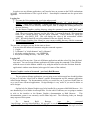
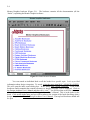
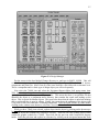
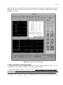
2-2
Tutorial
Introduction to Digital Design
with Mentor EDA Tools
Purpose
The purpose of this tutorial is to familiarize you with the basic set of Mentor Graphic EDA tools
including Design Architect (or just plain da). DA is Mentor Graphic's schematic capture program
that runs on the Sun IPX workstations in the Department of Electrical Engineering. During the
course of this tutorial, you will use Design Architect and Quicksim II to experiment with some
standard logic components. Although this is a fairly simple process, you will go through most of the
steps needed to design other, more complex digital systems. This tutorial consists of two parts. In
part two, performed in a future lab, you'll explore hierarchical design with da as well as more
advanced features of Quicksim.
This tutorial will tell you how to do some operation one way and one way only for the most part.
Be aware however that there are typically a myriad of ways to do any one thing in Mentor
applications, including using menus, commands, strokes, function keys and typed commands.
This tutorial will by no means make you an expert at using Mentor tools. In particular there is no
attempt made to show you how to recover from anything other than the simplest of errors. Should
you wish to explore further, you can read through the Design Architect User's Manual or the Design
Architect Reference Manual. There is also a much more in depth Mentor supplied tutorial called the
Design Architect Training Workbook but be prepared to spend about 40+ hours on that! There are
various Getting Started With... manuals that can also prove to be useful.
Notation
x Typed commands are given like: "cd dirname"
x Mouse commands are given like:
o LMB – left mouse button
o MMB – middle mouse button
o RMB – right mouse button
x Menu commands are given like: Menu>Item where Menu refers to the main pull down menu item
or the popup menu title and the greater sign is used to separate menu items.
x The key Ctrl-D means to hold down the control key while pressing the d key. Alt-F1 and Sh-F1
similarly mean to hold down the Alt (or Shift) key while pressing the F1 function key.
x Keyboard commands such as CLOse SESsion mean that the command can be abbreviated as clo
ses. Upper case is used to indicate the required keystrokes. Commands are not case sensitive and
may be entered as either upper or lower case.
Getting in and out
3-3
In order to use any Mentor application, you'll need to have an account on the UNIX workstations
in 106EE. An introduction to Unix is given in lab 1. Some helpful commands are also given in the
appendix.
Logging On
1. Log onto the Unix station using your login and password.
2. Create a directory for this tutorial by typing the three commands: "cd", "mkdir digital1", "cd
digital1". These three commands 1) makes sure that the current directory is your home
directory, 2) makes a new directory called digital1, then 3) changes the working directory to
the new directory.
3. Set the Mentor Graphics working directory using the command “setenv MGC_WD `pwd`”
(you may also use the swd alias instead). Note the use of reverse quotes around the command
pwd. The reverse quote character is to the left of the '1' on most keyboards. This inserts the
name of the current directory into the setenv command. Check yourself by typing the
command: echo $MGC_WD. This will display the value of the environment variable
MGC_WD which should be set to the pathname of the new digital1 directory.
4. Set the Mentor Graphics User Library to your current working directory with the command:
“setenv USERLIB `pwd`” (you may also use the sul alias instead).
The next time you login; you may do the same as above:
You may enter the mentor environment using the command sequence
1. <Login>
2. "cd dirname" or "mkdir dirname" and "cd dirname"
3. sul (in the working directory – sets USERLIB)
4. swd (in the working directory – sets MGC_WD)
Logging Off
You can log off at any time. First exit all Mentor applications and then select Exit from the Sun's
root menu. You can exit any Mentor application by either typing the command CLOse SESsion
while the cursor is in the Mentor window or by using the mouse to select the Exit item from the
application's window menu button (in the upper left corner of the window).
Mentor Graphics version of Acroread – previously Bold Browser
The two primary Mentor applications you are going to use in this tutorial are da and Quicksim
II, but we’ll also take a brief look at Mentor’s on-line documentation and file manager application
called Design Manager. The documentation will be very useful for you if you have trouble later on
or go on to more advanced applications. Design Manager is very useful if you need to delete or
move designs.
On-line help for Mentor Graphics used to be handled by a program called Bold Browser. It is
now handled by a set of Adobe Acrobat pdf files. For the sake of coherency we are going to continue
to refer to the interface to the Mentor Graphics documentation as Bold Browser.
This
documentation system is an extremely useful online help tool. The following leads you through
many aspects of this system.
To
launch
Bold
Browser,
type
the
command
“/mgc/bin/mgc_acro/mgc/shared/pdfdocs/_bk_mgc.pdf” or use the shortcut “bb”. This will invoke a
copy of Adobe Acroread with several Mentor Graphics extensions and will open the top level of the
2-4
Mentor Graphics bookcase (Figure 2-1). The bookcase contains all the documentation (all the
“books”) explaining the Mentor Graphics software.
Figure 2-1: Bold Browser Window
You can search an individual book or all the books for a specific topic. Let’s try to find
information about design viewpoints. To search, select the menu item MGC->SEARCH->QUERY.
This will open the index search dialog box. In the dialog enter ‘design viewpoint’. A list of the
bookcases and/or manuals that contain references to ‘design viewpoint’ will be displayed. Click on
the Design Architect User’s Manual and then click “view”. You will be taken to the first occurrence
of the words ‘design viewpoint’ in the Design Architect User’s Manual. This is in the index for the
book. Click on the index entry and you will be taken to the section of the book describing what a
design viewpoint is. Close the Design Architect User’s Manual. The top-level bookcase should still
be open.
3-5
Figure 2-2: Design Architect User's Manual
Now try a search on your own. Find the top level bookcase for the Quicksim II bookcase. Select
the Quicksim II bookcase and then select the Quicksim II User’s Manual. Navigate to the table of
contents. Now select Quicksim II design flow. Scroll though the section a little. Now press the
button several times to return to the bookcase. The buttons perform the following tasks:
Go to the previous view, even across books
Go to the next view (after the previous view button has been used)
Go to the first page of this book
Go to the last page of this book
2-6
Turn back one page in this book
Turn forward one page in this book.
This concludes your tour of Mentor Graphics online documentation. Remember to check here
whenever you have questions about using Mentor Graphics.
Design Manager
Design manager (dmgr) is similar to other file management programs in that it provides you with
an iconic view of directories and files and gives you a 'point and click' way to launch applications
like da and Quicksim II. It's very handy with Mentor tools since a typical design object like a
schematic drawing consists of several files and directories called a fileset. Keeping track of all the
resulting filenames can be confusing if done at the normal shell level but is straightforward with
Mentor's design management tools. Quite a bit of dmgr's functionality is also available in Mentor
tools under the MGC>Design Management menu item. Do not use Unix file commands like mv and
rm to manage Mentor files unless you are an expert Mentor user! You can easily create a mess by
breaking references or losing important components of filesets.
From the csh prompt, bring up dmgr with the command dmgr. You should see a typical Mentor
application window like that shown in Figure 2-3. Inside the client area you'll see two child
windows, one marked 'Tools' and the other with your digital directory pathname for a title. The latter
window is called a navigator window. It will most likely be empty since you haven't created any
design objects yet. Notice that there are Sh-Fcn keys, Ctrl-Fcn keys, and Alt-Fcn keys defined at the
bottom of the window. The shift-keys are lined up with the little “s”, the control-keys with the “c”,
and the alternate-keys with the “a”.
Try selecting one of the Tools in the tools window (click the LMB on it) and notice that changes
the tools popup menu. After you select a tool, try hitting the F2 function key to unselect it. F2 is
very useful and is available in all applications.
You may have noticed a row of 5 buttons at the bottom of the navigator window. These five
buttons enable you to 1) explore down into a directory, 2) return to a parent directory, 3) list
references to other objects (if any), 4) return to an object, and 5) goto a new directory respectively.
These navigator buttons make it fairly easy to work through a design hierarchy. Let's try them out by
exploring one of the Mentor parts libraries.
Click the MMB in the navigator window to select it and make it the active window. You'll need
to do this anytime you want to issue commands to a particular window. Notice that the title bar of
the active window is a different color from the inactive (tools) window. Next, click the LMB on the
navigator button that looks like four arrows. This is the goto button.
3-7
Figure 2-3: Design Manager
Put the cursor in the box labeled Change directory to: and type in $MGC_LSLIB. This will
switch the navigator to the ls_lib directory where you'll see two different kind of objects:
components and plain files. Most if not all of the icons look like a file folder with a schematic on it.
This is a component and is a basic type of design object you will see frequently.
Now select the 74ls00 icon and select the Navigator>Report>Object Info popup menu item.
What function key also performs this operation? The report shows that this is an mgc_component
type object, and has a directory as a fileset member. This means that there is an attribute file that
identifies the object as a component and a directory that contains the actual stuff making up the
object. This is typical for Mentor objects. The report also shows that the object is unlocked meaning
that no application has it open for editing. Finally, the report shows the pathname of the object (with
a soft prefix in this case) and some versioning information. Close the report window by either double
clicking on the window menu button or select the Close item from that menu.
While you have 74ls00 icon selected, explore down into the object by clicking on the down arrow
button. There you should see yet another new object named part. This is a basic element of a
component object that contains the component interface. There are also four symbol objects which
contain the graphic symbols for a 74ls00. These look like the part icon with a small block diagram
inside. Select the part icon and explore its references by clicking on the navigator button that looks
2-8
like a right arrow. You should see a list consisting of references to the four symbol icons. The four
symbols include the two deMorgan equivalent symbols for a two input NAND gate and the IEEE or
ANSI standard symbol as well as an old Mentor symbol included for compatibility with previous
versions of the tools. Return to the parent by clicking on the left arrow button. Click on the up arrow
navigator button to return to the library.
Return to your original directory by clicking on the goto button and specifying $MGC_WD in the
change directory to: box. As you can see, the navigator window forms a convenient way to navigate
through a hierarchical design as well as for obtaining all sorts of information about a design object.
Entering a Schematic with Design Architect
Now we'll bring up Design Architect (called da) which is the schematic capture program. You'll
use da to construct a schematic model of four basic TTL gates like that shown in Figure 2-4.
Starting DA
Start da by typing "da" at the csh command prompt. A window will pop up that looks something
like that in Figure 2-4 without the circuit of course.
Opening a New Sheet
Open a schematic sheet by hitting the F1 function key. This will bring up the Open Sheet dialog
box. Type in the name 4parts in the Component Name box. Make sure the rest of the box looks like
that shown in Figure 2-5. Leave the sheet name as sheet1 and make sure Editable is selected. OK
the dialog to create and open the new schematic. The first time you do this da will bring up an empty
schematic sheet window. The next time you use Open Sheet you'll get your existing schematic back
assuming you save it.
Selection Count
Notice the line just under the main menu bar and just above the schematic sheet. It should read
something like:
Sel: 0 (W|dae) (4parts|schematic|sheet1) () ().
The Sel field is the selection count. We'll get back to that later after you place some parts.
The symbol window, schematic palette, and context window
The da main window looks a lot like other Mentor applications. Along with the window elements
you've seen in dmgr there are three new windows along the right hand side of the screen: the active
symbol window, schematic palette, and context window. Click the RMB (menu button) in each of
these three windows to see what kind of popup menu is available in each. The symbol window is
where part symbols from a library will appear during placement, the palette window contains a
variety of command icons that are useful shortcuts for various menu commands, and the context
window shows the relative position of the schematic window on the overall schematic. The session
palette has an Open Sheet icon which does the same as the F1 function key used earlier. Use it if you
wish but do NOT use the similar looking but totally different Open Design Sheet icon, command,
menu item, or function key. This command uses an object called a viewpoint and can cause all sorts
of subtle problems unless you know what you're doing.
3-9
Figure 2-4: Design Architect Window
Figure 2-5: Open Sheet Dialog Box
2-10
Place the cursor somewhere in the message area (the narrow window below the function key
template window) and click the MMB. This will make the session window the active window. It
will also bring up the session palette. Click the MMB on the schematic window. That will bring
back the schematic palette and make the schematic window active. Notice how the palette icons
change when you switch from window to window. The schematic palette has ten rectangular buttons
at the top and a number of icon buttons at the bottom. The ten at the top stay constant and the icons
at the bottom change depending on whether you are in the Add/Route, Text, or Draw mode. Click
the LMB on the Text, Draw, and Add/Route buttons and note how the icons below change. Click on
the session button to bring the session palette back. Finally, click the MMB on the schematic sheet
window to bring the schematic palette back.
Specifying a Library
You'll need six parts for the 4parts schematic: a 2 input nand, 2 input nor, 2 input and, and a 2
input or, as well as input and output ports. These will all come from the spartan library. Select the
Library>XLNX>spartan lib from the pulldown menu. That command will display the xact library
palette where you should select the Unified library (not the obsolete library). From the Unified
palette, you can select the spartan LIB library. The spartan library will give you a choice of 'by type'
or 'all parts'. Select ‘by type’. In the spartan by type palette you can find most of your parts for this
exercise in the IO or LOGIC categories. In particular, IO contains portin, portout, ibuf, obuf, ipad,
and opad symbols. LOGIC contains such components as and2, or2, nand2, nor2, inv, and other parts
similar to Uyemora's primitives. Select LOGIC for now
Placing Parts
Now let's select a part from the library and place an instance of it on our schematic scheet. Select
a two input AND gate by clicking the LMB on it and clicking the OK button in both windows. Place
the AND gate in the middle near the top of the window like that shown in Figure 2-4 and click the
LMB to drop the part. Change the old ANSI symbol to the standard IEEE symbol by clicking the
RMB and selecting Replace>Alternate Symbol. Notice that the part remains outlined in white and the
select count (Sel: in the upper left corner) is now 1+.
Selecting parts
All Mentor graphic applications work on a select an object and do something to it paradigm.
This usually works just fine but occasionally results in unexpected behavior when you have
something selected that you didn't know about. Keep your eye on the select count and occasionally
hit the F2 key to unselect everything. Try that now to see what happens to the AND gate. You
should see the part turn blue with small purple diamonds identifying the part's pins. The pins are the
only place on the part where you can make a connection. Carefully place the cursor on one of the
pins and click the LMB. Notice that the pin turns white and the Sel count increments by one. If the
whole part turns white, hit F2 and start over. Select each pin in turn and notice the select count
increment. Finally, place the cursor to the upper left of the part, hold down the LMB and drag a
rubber band box out to enclose the entire part then release the LMB. Notice that this selects
everything and the selection count goes up to 4. Hit F2 to unselect everything.
3-11
Strokes
This is a good time to introduce strokes. Strokes are a handy shortcut for many common
operations. They involve holding down the MMB and drawing a simple shape with the mouse much
like using a pen. They can dramatically decrease design time. Carefully hold down the MMB and
draw a short diagonal line in a north-east direction then release the MMB. This is the zoom out
stroke and you should see the schematic image shrink. Zoom in is a short diagonal stroke in the
southwest direction. View all is a short diagonal in the north west direction. There is a view area
stroke but the F8 key may be easier to use to zoom in on a particular area of the screen. You can also
use the scroll bars on the sides of the schematic window to pan the image around. A short horizontal
stroke from left to right serves the same function as the Enter key or clicking on an OK button while
a short horizontal stroke from right to left serves as the cancel button or Esc key. Finally, a stroke in
the shape of the hook part of a question mark brings up quick help on strokes with a picture of the
various defined strokes. These strokes are shown in the appendix.
Next, place a 2-input NAND gate below the 2-input AND. As before, click the LMB on the part
name in the library, move the ghost image of the part into place, and click the LMB to drop it. Place
a NOR below the NAND and an OR below the NOR, as in Figure 4.
Changing symbols
Just to be different we'll use the DeMorgan's equivalent of the NOR and OR gates to make them
look like active low AND gates. Hit F2 to deselect everything then select the NOR. Click the RMB
to bring up the popup menu and select Replace>Alternate Symbol from that menu. This will cycle
through the other symbols for the part if there are any. The first time you do this for the NOR you
may not notice anything happen since two of the symbols look alike. In order to repeat the last
popup menu command, hold down the CTRL key and click the RMB. Slowly do this several times
and watch the different symbols as they appear. Leave the DeMorgan equivalent for the NOR gate
on the schematic. Repeat this for the OR.
Port-in
We now have all four parts placed but we need a way to input and output signals. Bring up the
symbol history dialog box by hitting the Ctrl-H key. Select portin and OK the box. To place a part
from the active symbol window, place the cursor in the active symbol window, click the LMB, and
drag the ghost instance into place. Click the LMB to place the part. If you make a mistake and drop
the part accidentally, just hit the Del key to delete the selected part and start over. Place the portin
symbol about 7 grid points to the left of the top input pin of the AND.
Copying parts
We could use this same procedure to place all i/o ports but let's examine a couple of other
procedures instead. Hit F2 to make sure everything is unselected. Then place the cursor over the
portin symbol you just placed and click the LMB to select it. The whole symbol should turn white
and the select count should be 1+. If not, hit F2 to unselect everything and start over. With the
portin selected, hold down the Ctrl key and the middle mouse button (MMB) and then move the
ghost image of the portin copy down about 2 grid points. Release the mouse button to drop the
instance into place. Notice that the first portin has been deselected and the new portin copy remains
selected. Use this same procedure to place four instances of portout like those shown in Figure 2-4.
Be sure to use portout and not portin for the output ports.
2-12
Wiring Parts
After you have placed some parts you can begin to wire them up. We call this drawing nets. A
net is a set of connected wires that circuit theory texts often call a node as in node voltage. Nets can
only be used to join pins on parts. To draw a net, press the F3 function key to bring up the Add Wi
prompt bar. Move the cursor to the output pin of the AND and click the LMB. Next, drag the rubber
band line to the top portout's pin and double click the LMB. This completes the net. Notice that the
net remains selected. Hit F2 to unselect the net. Notice also that the prompt bar stays up. You can
continue adding nets in this fashion as long as the prompt bar is active. Hit ESC to terminate the
prompt bar after you are finished drawing nets.
Finish wiring the rest of the circuit like that shown in Figure 2-4. Notice that when you click the
LMB you add another vertex to the wire. You terminate a wire by double clicking the LMB. A net
that ends at a pin or another net is connected to it but one that just crosses another net is not
connected.
Connecting nets
Connected nets are indicated as such by a small connection dot or box. Occasionally you may
see a not dot that looks like a circle with a slash through it over two nets that are close to one another.
This frequently happens when you use copy to add a net instead of the usual Add Wire command. If
that happens and you really want to make a connection in place of the not dot, hit Sh-F6 to connect
all. If you add a wire you don't want just select it and hit Del to delete it. Click on the Undo button
on the schematic palette to undo a command.
Saving your work
It's a good idea to save your file periodically to avoid loss of valuable work. To save your file
simply select the File>Save Sheet item from the main menu. Da will probably complain that the
sheet has not been checked but just ignore that for now.
Opening previously saved work
After saving your file, close it by selecting the schematic's window menu Close item. This
should bring you back to the original da session screen with a large empty gray client area. Click on
the Open Sheet button on the palette as before to bring up the Open Sheet dialog. This time, click on
the Navigator button to bring up a navigator window. This window has basically the same
functionality as dmgr. You should see your 4part component identified as such by a small icon that
looks like a file folder with a C inside. Notice the familiar navigator buttons that allow you to
navigate through a directory hierarchy. Select 4part and OK the box. Notice that the component
name has been filled in for you. OK the dialog box and you should see your 4part schematic again.
At this point in time you should be able to create and edit simple schematics.
Naming Nets
Next we'll change the names on the input and output ports. These names are properties attached
to the port's pins. Properties can be attached to either symbols or their pins. You can see a list of the
properties attached to a symbol by first selecting it (make sure nothing else is selected) and then
selecting the Report>Object item from the main menu. Two important properties are COMP and
3-13
MODEL which you should see listed in the report. Close the report by making a short horizontal
stroke to the left with the MMB or use the window menu button.
Naming Ports
All i/o ports initially have a visible property called NET with a value of NET. To change the
name of a port simply place the cursor over the top portin name and hit the Sh-F7 key. This brings
up the CHA PR VA prompt bar with the property name NET already filled in and the value NET
selected. If NET isn't selected, click the LMB somewhere in the New Value field. You can also use
the Tab key to move around inside the prompt bar. With the value NET selected, type an upper case
A for the new name and OK the bar. Repeat this for B and the four output ports. You can use this
technique to change any other visible property text as well. Make sure you change just the New
Value field and not the Property Name field and leave the type as string.
Position of text
If you don't like the position of some text item you can move it with the F7 key. Place the cursor
over the and2 netname and press the F7 key. While holding the key down move the and2 text so that
it appears on top of the portout.
Adding Comment Text
It's usually a good idea to add comment text like titles and the like to your schematic. You can do
this a number of ways but we'll use the palette. Select the text button on the palette. On the
schematic_text palette, look for an Add Comment button. You may need to hit the Page Down key a
couple of times to make it visible. Click on that one to bring up the Add TExt prompt bar. Fill in
some descriptive text (like TTL Gates) and OK the bar. Since you haven't finished specifying the
location, the bar stays up and the At Location item is selected. Move the cursor and your text moves
along with it. Click the LMB to fix the position and the prompt bar will disappear. More than likely
the text height won't look right. With the text selected, pick the popup menu item Change Height>
2.0 x pin spacing.
Selecting Text
Now unselect the text by hitting F2. Try to select it again by clicking the LMB on it. What
happens? If you said 'nothing' you're correct! This is because the select filter has been set to exclude
comment text. Hit Ctrl-F to just see what the filter is set to but don't change anything. Notice that
comment text isn't included and then hit ESC to cancel the filter dialog. We could have included
comment text by clicking on the selector button next to comment text but that might mess things up
later on. An easier way is to simply use the F1 (select area all) key. Place the cursor over the
comment text and just hit F1 to select the text. You can also drag out a selection rectangle by holding
the F1 key down and moving the mouse but it's usually sufficient to use F1 this way to select single
items. Hit F2 to unselect everything.
Checking for Errors
At this point in time your schematic should look similar to Figure 2-4. Make sure everything is
connected. Before you can use a schematic with the other tools it must be checked for errors. Pick
the main menu item Check>Sheet. If all went well you should see a report that indicates there are no
errors.
2-14
Normally this won't be the case so let's create an error condition to see what happens. Hit Ctrl-H
which will bring up the symbol history dialog. Choose a part from the history list and OK the box.
The active symbol window changes to display the selected part. Place an extra instance somewhere
on the sheet so that it doesn't touch any other part. Hit F2 to unselect the part. Now run
Check>Sheet again to see what happens. This time you should see a warning that you have one or
more unconnected pins or dangles.
Viewing Errors
Place the cursor over the instance name with an error, which will be something like I$819, and
click the LMB to select it. Pop the schematic window by clicking the MMB on it somewhere. The
MMB is a safe button to use since it doesn't change the Sel count. Notice that the instance has been
selected. This is called cross selection and is a common feature across all Mentor tools. You can
generally select an object in one window and have it selected in all windows. Now pick the
View>Selected item from the main menu. This will zoom in on the selected items and, along with
View>Centered, is a handy way to find the location of errors in the Check>Sheet report. Now make
sure the extra part is still selected and hit Del to erase it.
Printing your Schematic
Before printing, run Check>Sheet again to verify that there are no errors and run Save>Sheet to
save your file.
To print the schematic, select File>Print Sheet from the main menu. The pop-up that appears
should show the sheet will be printed to printer “mentor”. This is the printer in the Unix lab. Hit
“OK” and your sheet will be printed.
Finishing up
Close da by selecting Close from the main window menu. This will return you to the Design
Manager. Close da's transcript window by selecting Close from its window menu.
Using Quicksim II
Start the simulation tool, Quicksim, by typing “quicksim 4parts” at the Unix command prompt.
(As with design architect, it is important to be in the correct directory, and to have already typed sul
and swd to set the working library and directory). You should see a Quicksim II main window like
that is shown in Figure 2-6 (without the circuit and simulation windows). Don't be dismayed by how
slowly Quicksim II initiates. Once it gets loaded the simulation speed is quite fast even on very large
designs of 1000's of gates.
Maximize Quicksim to make it fill the screen.
Displaying a schematic
In order to make our window look like Figure 2-6 we need to do a little setup first. Select the
Open Sheet icon from the tool palette. The icon looks like an eye looking at a schematic. This is a
mnemonic for looking at the design through a Viewpoint. We'll do more with viewpoints in the
second half of this tutorial. For now, be aware that all Mentor downstream tools like Quicksim II use
3-15
them and that they are basically containers for holding various design configuration data such as
simulation test data. When you select Open Sheet you'll see a miniature version of your schematic
displayed in a window.
Figure 2-6: Quicksim II Main Window
Opening a List Window and Selecting Signals
Simulation results can be displayed in either a List window like that shown in Figure 2-6 or as
waveforms in a Trace window. We'll use a list window in this exercise.
Start by selecting the signals you want to trace. Click the MMB in the schematic window to
activate it, then select all of the input signals by placing the mouse cursor to the upper left of input A,
hold down the LMB, and drag a rubber band box over both A and B. Release the mouse button and
you should see the nets attached to A and B highlighted. If both nets aren't selected, hit F2 and do it
over again. You can select a single net by placing the cursor on the net and clicking the select
2-16
(LMB) mouse button. Select the four output signals as well as the input signals. Now select List
from the Tool palette and you'll see a List Window displayed with the signals you just selected.
The little box displayed above each signal name in the List window is called a gadget and is used
to select a signal in only the List window. This is useful if, for example, you want to delete a signal
from the List window but not the Trace window. In order to delete a signal, just select its gadget and
click on the Delete item in the palette. You can always add it back by selecting the signal in the
schematic window and clicking on List again.
Defining Test Inputs
We'll define a simple grey code test pattern to drive our collection of four gates. This will
provide an exhaustive test pattern of all four combinations of two inputs. There are many ways to do
this as usual but we'll use one of the most straight forward: the FORCE command. The stimulus
palette contains a number of useful command icons for more complex stimuli.
We'll start out by adding the inputs to a Trace window so that we can watch the effect of our
FORCE commands. Hit F2 to make sure nothing is selected, then select the two inputs (A and B) in
the schematic window. Click on the WF Editor (waveform editor) button in the palette to get the WF
Editor command icons, and then click on the Edit Waveform icon to bring up a Trace window with
the A and B signals displayed like that shown in Figure 2-6. The names of the signals (forces@@/B)
indicate that they are coming from the forces waveform database and aren't the results of simulation
like those shown in the List window.
Click your mouse in the bottom of the window (in the command window) and type the command:
FORCE B 0 0. The case isn't important. Either upper or lower will do. This command tells
Quicksim II to force signal B to a 0 at time T=0. The time value in the force command is relative to
the current simulation time. Notice that the trace display for B changes from a light blue line in the
middle to a magenta line below the line of +'s. A low line corresponds to a zero, a high line to a one,
and a line down the middle corresponds to an unknown level (X). This usually means that the signal
hasn't been driven to either a one or a zero. The colors are significant and indicate the strength of the
signal: charged (weak), resistive (stronger but can be overdriven like it's being driven through a pull
up resistor), and driven (like it is grounded or wired to the power supply). This is also indicated in
the List window by the Xr (unknown-resistive). Next type the command FORC B 1 200 to force B
to a one at T=200nS. Force can be abbreviated as FORC. Now use what you've learned and type in
three FORCE commands to generate the waveform shown for A in Figure 2-6. If you make a really
bad mistake you can always delete a signal by selecting its gadget and then typing the command DEL
FORCe. When you're finished, check to make sure the Trace window looks like that shown in Figure
2-6.
Running a simulation
To run a simulation using the forces you just set up simply type the command: RUN 400. Run
400 tells Quicksim II to advance time from the current time (T=0) by 400nS, apply any inputs in the
forces database, and display any events which occur.
Notice that when an input changes the output changes (if any) don't take place until 0.1nS later.
Real parts normally have a longer propagation delay which can vary from part to part, with
temperature, loading, and whether the signal is rising or falling.
Now repeat the RUN 400 command to see what happens. Notice that time advances by another
400nS to T=800. There are no new events so the List window stays the same as it was.
Rerunning a simulation
Normally you'll want to restart the simulation from T=0 from time to time. Click on the Reset
button to start the simulation over. This will bring up a Reset dialog box. Click on the State button
3-17
which will open another section of the dialog. Click on the Save Results button to clear it since we
don't want to clutter up our disk space with junk and then OK the dialog. Now rerun the simulation
for 400nS just to see that time really did reset to 0.
Using the List window, verify that the four gates behave as expected. When you are satisfied that
the functional simulation is performing correctly, reset the simulator back to 0.
Full-Timing Simulation
Next we'll run a full timing simulation, rather than use the simple unit-delays we saw in the last
simulation. In order to do that you need to switch the simulator from a Unit delay simulation to a
Delay simulation. Select Setup>Kernel>Analysis from the main menu using the RMB. This will
bring up the Setup Analysis dialog box. Click on the Delay button to select the full timing mode and
then click on the Visible button to open up the details of the delay mode. This will enable you to
pick minimum, typical, or maximum propagation delays as well as a variety of constraint checking.
The Timing Mode field will normally show 'typ'. If it doesn't, click on the Change... button and
select Full Delays 'typ'. Make sure that all of the constraint buttons are clear and OK the dialog box.
Printing the List Window
Run the simulation for 400nS again and note that the output signals exhibit a propagation delay of
typical TTL values instead of the 0.1nS unit delay. Use a TTL data book to verify that the rise and
fall propagation delays of all four gates are as expected. You'll need to modify the A signal in order
to get both rising and falling delays for the or2 and nor2 gates. Make a hardcopy of the List window
by activating the List window and selecting the File>Print item from the main menu.
Leaving Quicksim II
You exit Quicksim II just like any other Mentor application. Simply pick the Close item from the
window menu button in the upper left corner of the session window or type the command CLOse
SESsion. Select without saving from the dialog box which appears since it's not worth saving this
little simulation.
Logging Off
Logoff by placing the cursor in a blank area of the screen (this is called the root window), click
the RMB to bring up the Workspace menu and pick Exit. Confirm that you want to exit and make
sure the system displays the login prompt after shutting down the window system. Under no
circumstances should you leave a workstation logged on.
Going Further
Congratulations! If you've finished this tutorial you are well on your way to becoming proficient
with one of the leading state of the art, industrial strength EDA tools.