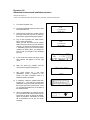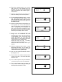
1
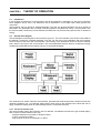
SERVICE INFORMATION PHYACTION 190 / 190i Copyright© Uniphy BV 1996-97 Phyaction® is a registered trademark of Uniphy BV Art. Code 93001212.6 Phyaction is manufactured in The Netherlands by Uniphy BV P.O.Box 558 , NL-5600 AN Eindhoven, the Netherlands Tel. +31 499 491800 Fax. +31 499 474734 Table of contents GENERAL INFORMATION ......................................................................... Introduction ................................................................................................................................ Safety aspects ............................................................................................................................ Installation .................................................................................................................................. Description of the controls ....................................................................................................... Technical specifications............................................................................................................ 1 1 1 2 2 4 THEORY OF OPERATION .......................................................................... Introduction ................................................................................................................................ General block diagram .............................................................................................................. Ultrasound unit........................................................................................................................... 5 5 5 6 CHAPTER 1 1.1 1.2 1.3 1.4 1.5 CHAPTER 2 2.1 2.2 2.3 CHAPTER 3 3.1 3.2 3.3 PERFORMANCE CHECK ............................................................................ 9 Safety inspection ....................................................................................................................... 9 IEC 601-1 safety tests ............................................................................................................... 10 Performance check of the ultrasound treatment heads ....................................................... 10 TROUBLE SHOOTING ................................................................................. 12 Introduction ............................................................................................................................... 12 Description of the automatic selftest...................................................................................... 12 Description of the service software ........................................................................................ 15 Error messages ......................................................................................................................... 16 CHAPTER 4 4.1 4.2 4.3 4.4 EXCHANGING BOARDS AND MODULES .................................. 17 Introduction ............................................................................................................................... 17 Exchanging the software or the main board (PCB 192X) ..................................................... 17 Exchanging the ultrasound module........................................................................................ 17 Exchanging the LCD ................................................................................................................. 18 Exchanging the keyboard PCB (194X).................................................................................... 18 CHAPTER 5 5.1 5.2 5.3 5.4 5.5 APPENDIX 1 CIRCUIT DIAGRAMS APPENDIX 2 TUNING THE ULTRASOUND TREATMENT HEADS APPENDIX 3 ERROR LIST Table of contents - Service information Phyaction 190 / 190i CHAPTER 1 GENERAL INFORMATION 1.1 Introduction The Phyaction 190 is an appliance for ultrasound therapy and it can be used for combination therapy with an external electrotherapy appliance. In this chapter the important features from the users manual for service personnel are listed. In the next chapter the theory of operation will be explained. In chapter 3 is described how service personnel can check the operation of the Phyaction 190 and what maintenance operations should be carried out. The next chapter contains information which could be very useful for trouble shooting such as a description of the automatic self test and a list of the error numbers. The operations that have to be carried out if you want to exchange a printed circuit board or another module are described in chapter 5. 1.2 Safety aspects 1.2.1 Electrical safety The equipment can only be used in areas with provisions in accordance with current statutory requirements. Pay particular attention to the use of protective earth, otherwise the patient leakage current can rise above the permitted limit for type BF equipment. 1.2.2 Explosion safety The equipment is not suitable for use in areas where flammable gasses or vapours are present. Therefore, remove the mains plug from the socket before the area in which the equipment is located is disinfected, since some disinfection solutions evaporate and subsequently form an explosive mixture. 1.2.3 Operational safety - Using the equipment in the vicinity of short wave or microwave equipment can influence the correct operation of the unit. Using this equipment when high frequency surgical equipment is connected to the patient at the same time can result in burning under the electrodes when using it for combination therapy. - Patients who have electrical implants (i.e. pacemaker) may only be treated following medical advice. - The equipment is not suitable for use in damp areas. - The equipment may not be disinfected or sterilized. - Whenever the equipment is switched on (using the main switch) the microprocessor checks the entire system for correct operation. - The ultrasound heads, including the cable and the connectors should be checked regularly. In particular attention should be paid to damage to the ultrasound heads through which liquids can enter the ultrasound heads. - The ultrasound heads should be handled carefully, because the properties of the ultrasound heads can alter due to rough handling. 1.2.4 Use of the appliance The equipment and accessories should only be used by authorized personnel and in accordance with all instructions included in these operating instructions. The Phyaction 190 is only to be used for providing ultrasound therapy. When connected to an electrotherapy appliance the Phyaction 190 can be used to provide combination therapy. 1.2.5 Radio interference suppression and electromagnetic compatibility This equipment meets the guidelines for ISM equipment relating to electromagnetic compatibility and is radio interference suppressed according to EN55011. Also see section 1.2.3 Operational safety of this chapter, concerning the use of the equipment in the vicinity of short wave and microwave equipment. 1. GENERAL INFORMATION Service information Phyaction 190 / 190i - Page 1 1.3 Installation 1.3.1 Incoming inspection Check that the equipment and ultrasound head(s) have not been damaged during transportation and that the accessories are intact and complete (see chapter 14 ACCESSORIES of the INSTRUCTIONS FOR USE). In the event of damage and/or defect you should inform your supplier. 1.3.2 Mains voltage Your equipment is suitable for a nominal voltage of 110, 220, 230 or 240 Volt AC, 50-60 Hz. Indicated on the rear of the equipment will be the voltage for which it has been wired. You can not alter this yourself. Carefully check this data before you place the mains plug in the socket. The mains input is on the back of the appliance at the bottom. 1.3.3 Functional test During production the equipment is tested for electrical safety. Whenever the equipment is switched on, the processor performs an extensive test to ensure that the equipment is operating correctly. In addition you must check whether the display and the indicator lamps are operating correctly. The green lamp indicates that the appliance is connected to the mains supply and that the appliance is switched on. The red lamp illuminates when the safety system has detected a fault which prevents the appliance being used. If the appliance is not operating correctly, then you must not use the equipment and you must contact your supplier. If you can not read or if it is difficult to read the display, then press the right hand blue button and the black ¿ button in order to darken the text or the black À button if you want to make the text lighter. 1.3.4 Location and transportation The equipment must be set up horizontally and stable. You should ensure that the vents in the housing are not blocked so that circulation of air is not hindered. Objects must not be placed on the equipment and you must ensure that no liquid enters the equipment. 1.3.5 Fitting the head holder As standard, a head holder is supplied with each treatment head. Before you use the Phyaction 190 for the first time, we advise you to fix the head holder(s) to the appliance. The ultrasound treatment head can be connected to the appliance easily and in a user-friendly manner into the head holder. At the same time this protects the treatment head against damage by, for example, falling. For a description of fixing the head holder to the appliance please refer to the drawing which you will find in the packing for the head holder. 1.3.6 Checking the ultrasound heads You can check which head belongs to which appliance by pressing the yellow button for 3 seconds. In the middle of the screen which then appears, you will see the treatment head symbol with a statement of the ERA on which treatment head(s) the appliance has been tuned. After this symbol there are 20 figures. If these figures correspond exactly with the figures on the treatment head label then this treatment head belongs to that appliance. If they do not correspond, you are using a treatment head which does not belong to that appliance. If the middle screen is completely empty then the appliance has not been tuned to any treatment head and we advise you to inform your supplier. 1.4 Description of the controls On the last page of this operating instruction you will find an illustration of the equipment and the accessories. 1.4.1 Display The display1 consists of separate picture elements which are controlled by a processor so that you can see text and figures. When you are performing a treatment, the display shows all of the information you require: - The top left section provides information about the parameters which have been set. - The right section provides information about the output power and the degree of contact of the treatment head. This section also gives information about the treatment time. - The bottom line of the display shows the functions of the blue buttons. 1. GENERAL INFORMATION Service information Phyaction 190 / 190i - Page 2 Lay-out of the therapy screen 1.4.2 Signal lamps On the front, to the right of the display, there are two coloured lamps: - The green lamp2 indicates that the appliance is connected to the mains supply and that the appliance is switched on. - The red lamp3 illuminates when the safety system has detected a fault which prevents the appliance being used. A message appears on the display. See chapter 4 TROUBLE SHOOTING. The red lamp also illuminates during the self test which is performed after switching on the appliance. The yellow lamps4, beside the output connectors of the ultrasound head, illuminate for 2 seconds as soon as the relevant ultrasound head has been selected. A yellow lamp also illuminates beside an output connector as soon as ultrasound power is emitted. 1.4.3 Rotary knob On the right-hand side at the front there is a large rotary knob5 with which the intensity peak in Watt/cm2 can be adjusted. When you rotate this knob fully anti-clockwise you will feel a click and it is in the zero position. 1.4.4 Push buttons - Using the blue buttons 6 a parameter can be selected. This display clearly shows the function of the buttons. - The black buttons ¿ or À7 are used to increase or decrease the value of a parameter which you have already selected. - The yellow button8 is used to return to the therapy screen. When the yellow button is depressed for 3 seconds, a screen appears in which the software version number, the release date of the software and the treatment head parameters can be read. - Using the green button9 you can access the special memory function. 20 different treatments can be saved, retrieved or changed. 1.4.5 Output connectors and sockets on the front - The safety socket10 on the far left is used for connecting the electrode cable during combination therapy. The metallic treatment surface of the ultrasound head forms the other electrode. - The ultrasound head(s) are connected to the two connectors11 on the right. It makes no difference which head(s) you connect to which connector. Two treatment heads can be connected at the same time provided they do not have the same format. 1.4.6 Controls on the bottom at the rear of the appliance The following controls can be found on the rear of the appliance: - The mains input with mains switch12. - The fuse holder13 is located between the mains input and the mains switch. The rating of the fuse to be used is stated on the rear of the appliance. - The connector for connecting to the potential equalization busbar14. 1.4.7 Label on the rear of the appliance The label containing the appliance data15 is located on the rear of the appliance. 1.4.8 Ultrasound treatment heads You have the choice of two ultrasound treatment heads16 with an ERA (Effective Radiating Area) of either 1 cm2 or 4 cm2. The treatment heads can be easily located in the multi-functional head holder17. With each treatment head both 1 MHz and 3 MHz ultrasound can be applied. Both treatment heads can be connected to the appliance at the same time. Using the blue button you can select which you want to use. The display indicates which format of treatment head has been selected at that moment. As soon as the Phyaction 190 is switched on using the mains switch or from the stand-by position, or as soon as a treatment 1. GENERAL INFORMATION Service information Phyaction 190 / 190i - Page 3 head has been selected, the yellow lamp beside the selected head illuminates for 2 seconds on the appliance. Furthermore, each treatment head has a colour indication at two positions: the 4 cm2 treatment head is green and the 1 cm2 is yellow. When the surface of the treatment head makes insufficient contact with the patient this is shown on the screen. The ultrasound power is then automatically turned down so that overheating of the treatment head and subsequent wear is reduced. The treatment time also stops when there is insufficient contact and this starts again as soon as contact is re-established. In this way the set time is actually utilized. The appliance should always be tuned to the associated treatment heads. For every new appliance the heads are already tuned to the appliance. However, when a new (another) treatment head is purchased, the appliance should be tuned to the new head. When you press the yellow button for 3 seconds, a screen appears in which you can check whether you are using the correct treatment heads with the appliance. In Appendix 2 TUNING THE ULTRASOUND TREATMENT HEADS, the tuning process is described. 1.4.9 Head holder For each Phyaction 190 a head holder for each treatment head is supplied as standard. You can fit this to the appliance easily yourself. For a description of fixing the head holder to the appliance please refer to the drawing which is enclosed in the packing for the head holder. 1.5 Technical specifications 1.5.1 Specifications Phyaction 190 Duty-cycle: continuous 1:1 pulsating 1:2, 1:4, 1:8, 1:16 Treatment clock: adjustable 0-30 minutes, linked to contact control Intensity: 0 - 1.5 W/cm2 at 3.3 MHz continuous 0 - 2 W/cm2 at 0.8 MHz continuous 0 - 3 W/cm2 at 0.8 and 3.3 MHz pulsating Read-out: intensity in W/cm2 effective output power in W Pulse repetition frequency: 100 Hz Memory: 20 memory places available Combination therapy: possibility to connect an electrotherapy appliance 1.5.2 Specifications treatment heads ERA: 1 cm2 (model 91) and 4 cm2 (model 92) Frequencies: 0.8 MHz and 3.3 MHz BNR: < 5 at 0.8 MHz < 4 at 3.3 MHz The treatment heads are watertight according to IEC 601-2-5. 1.5.3 Technical information Dimensions: 38 x 22 x 15 cm Weight: 5 kg Insulation class: I, type BF Voltage: 110, 220, 230 or 240 Volt, 50-60 Hz Input current: maximum 300 mAeff at 220 V and 600 mAeff at 110 V 1.5.4 Replaceable parts Fuses in the mains entrance. 1. GENERAL INFORMATION Service information Phyaction 190 / 190i - Page 4 CHAPTER 2 THEORY OF OPERATION 2.1 Introduction In this chapter the electronics of the Phyaction 190 will be explained. A description on the level of functional block diagrams will be used. The electronics will be described in more depth when safety aspects are concerned. The Phyaction 190 is a device for ultrasound therapy. The user -the physical therapist- can set a number of parameters. The parameters are converted in electric signals for the ultrasound unit by a microcontroller. Also the microcontroller continuously checks whether the ultrasound unit produces the proper amount of ultrasound energy. 2.2 General block diagram The block diagram of the Phyaction 190 is shown in figure 2.1. The microcontroller core, shown in the middle of the diagram, controls the complete apparatus. The user can set most of the parameters with the keyboard, which is shown at the left of the microcontroller. The intensity of the ultrasound can be set with the intensity knob, drawn to the right of the microcontroller. The actual parameters and the amount of ultrasound energy actually being administered to the patient is shown on the graphical display. Figure 2.1, Functional block diagram of the Phyaction 190 The ultrasound unit, drawn under the microcontroller, generates the electrical signal the US-head converts into ultrasonic vibrations. The 4 mm banana safety socket, drawn close to the ultrasound unit, allows the user to apply combination therapy when an electrotherapy device is connected to this bus. 2.2.1 The microcontroller core The microcontroller used in the Phyaction 190 is an 80C552. The 80C552 is an MCS-51 type controller (8051) with a number of extra features on the chip: - 256 byte RAM memory (instead of 128 byte in 8051) - 3 timer / counters (2 in 8051) - eight channel 10-bit AD converter (N.A. in 8051) 2. THEORY OF OPERATION Service information Phyaction 190 / 190i - Page 5 - 5 eight-bit wide I/O ports (4 in 8051) - 2 eight-bit pulse width modulators (PWM) (N.A. in 8051) - I2C bus for serial data transfer (N.A. in 8051) - UART for serial data transfer (e.g. RS232) - watchdog timer (N.A. in 8051) Next to the microcontroller the following parts are present in the core: - 8 kByte (expandable to 32 kByte) RAM data memory - 1 Mbit EPROM program and constant data memory - 256 byte I2C E2PROM non-volatile data memory - 2 HCMOS IC's for decoding and buffering purposes 2.2.2 Keyboard The keyboard is a matrix of 10 push buttons connected to the microcontroller via an I2C I/O expander. The microcontroller software defines the function of each key. The user can use the keyboard to set and change a number of parameters (such as the active treatment head, treatment frequency, duty-cycle, treatment time etc.) 2.2.3 Graphical user interface A 240 x 64 dots LCD display with CFT backlight is used as graphical user interface. On it the user can see the current function of the function keys, the parameters, the remaining treatment time, the selected intensity and the resulting effective energy being radiated by the treatment head. Further the contact ration between treatment head and patient is shown on the display. 2.2.4 Safety socket The 4 mm banana safety socket is directly connected to the tin can of the ultrasound unit. This Tin can is the 'ground' of the circuitry, which is also connected to the metal front of the treatment heads. This socket can be used for combination therapy with external electrotherapy appliances. 2.2.5 Serial interface No serial interface is available to the user. Only with an opened apparatus the serial interface can be used for testing purposes. This interface is a 5V-level RS232 interface (a direct connection to the UART of the microcontroller). The interface is for extended service features (used by manufacturer only). 2.2.6 Power supply The power supply is a conventional one with a mains transformer suited for medical purposes. It is equipped with the required primary and secondary fuses, two bridge rectifiers and two capacitors. The unstabilised +29 V is used to feed the ultrasound unit. In the ultrasound unit the +29 V is further used to create a controlled ultrasound supply and two stabilized supplies of +24 V and +15 V. The unstabilised +9 V is used to create a microcontroller controlled switchable +8 V for the LCD contrast and its backlight and to create a +5 V for the logic components. A reset signal for the microcontroller and LCD is generated when the +5 V comes in or when it drops below a certain voltage. 2.3 Ultrasound unit The functional block diagram of the ultrasound unit is shown in figure 2.2. Since the signals to generate ultrasound are made using a square wave of about 1 MHz or 3 MHz, it is necessary to encapsulate the complete ultrasound unit, including the ultrasound crystal, in a metal case (a Faraday cage). In figure 2.2 the metal case is indicated by the dashed line. The electronics is put into a 'tin can'. It will be clear that the ultrasound treatment head cannot be put in the tin can, so to maintain the shielding the crystal is put in an aluminium cup, while the signal wire from the electronics to the crystal is a double braided coaxial cable (double shielded). The keyboard is used to set the various parameters, such as duty-cycle, treatment time and frequency (1 MHz or 3 MHz). The microcontroller computes the operating frequency of the crystal, using a couple of treatment head parameters fed to the apparatus at installation time. The same head parameters are also used to calculate the administered amount of ultrasound energy and the rate of contact between treatment surface and patient. Keeping track of the treatment time is also done by the microcontroller. 2. THEORY OF OPERATION Service information Phyaction 190 / 190i - Page 6 Figure 2.2, Functional block diagram of the ultrasound unit Countdown of the treatment time is stopped when the microcontroller notes that there is no or not enough contact between treatment head and patient. The intensity of the ultrasound can be adjusted by the user using the intensity knob. Depending on the voltage Vpotus the microcontroller computes and sets the required voltage Vus with the controlling voltage VSetUs in order to generate the desired amount of ultrasound. 2.3.1 PLL The required ultrasound frequency Fus of 0.8 MHz or 3.3 MHz cannot be generated by the microcontroller itself. For this reason a phase locked loop (PLL) is used to transform a low-frequent signal RefClock, that the microcontroller can generate, up to the desired steering frequency of 2XFus. The modulator divides this double frequency and mixes it with the desired duty-cycle. The frequency generated by the microcontroller is always around 400 Hz. In order to obtain ultrasonic frequencies of both 0.8 MHz and 3.3 MHz a programmable divider is used in the PLL. Whenever the PLL is out of lock (e.g. when changing the frequency for contact control calculations) the Lock-error signal is used to stop the modulator in order to prevent erroneous frequencies being produced by the treatment head. 2.3.2 Modulator To obtain a symmetrical steering signal for the power stage the modulator switches its outputs with half the input frequency. Also the modulator mixes the duty-cycle signal synchronously with the ultrasound frequency to prevent spikes. An amplitude modulation with 100% modulation depth (the signal being switched on and off) is the result of this mixing. With the Lock-error signal the modulator can be forced to shutdown. This action can be taken by the PLL when it is out of lock or by the microcontroller. The Lock-error line can be used as an input as well as an output by the microcontroller. 2.3.3 Voltage controller A pulse controlled downward converter voltage controller is used to convert the unstabilized +29V to the desired ultrasound voltage. The voltage controller is made in such a way that its output voltage is linear proportional to its input voltage VSetUs. Thus the microcontroller can adjust the ultrasonic power by setting VSetUs proportional to the square root of the desired output power. The microcontroller constantly monitors the output voltage of the voltage controller. If the output voltage is too high (because of a hardware failure), the microcontroller will shut down the ultrasound unit and give an error message. 2. THEORY OF OPERATION Service information Phyaction 190 / 190i - Page 7 2.3.4 Power stage The power stage is a switched balance class-D end stage. The generated output power is controlled by Vus, generated by the voltage controller. The above mentioned modulator controls whether the power stage is active. Power MOSFETs are used as switching elements. The MOSFETs are driven by buffers that also take care of a small delay in driving the MOSFETs, to prevent them of being active simultaneously. If either one of the MOSFETs has become defective, both of them should be replaced. In that case the adjustment of the delays in the FET-drivers should be carried out. This adjustment cannot be executed in the field, it has to be carried out only by Uniphy personnel. 2.3.5 Impedance matching The ultrasound crystal is mainly a capacitive load. Its impedance differs, among other things, with the size of the crystal and its operating frequency. For this reason the microcontroller can match the impedance by switching one or two inductors and when necessary capacitors in the output stage. 2.3.6 US head The ultrasound treatment head is of course a very important part of the apparatus. It converts the electric signal into ultrasound using a piezo crystal. This crystal, with a diameter depending on the desired head size, is glued in an aluminium cup that minimizes electromagnetic radiation and enables the crystal to be used on to operating frequencies. The aluminium cup can also be used as a second electrode if combination therapy is desired. A separate electrotherapy device needs to be connected to the safety socket for combination therapy. A resistor is in the connector of the treatment head to enable the microcontroller to detect whether a head is connected and to recognize the type of head that is connected. 2. THEORY OF OPERATION Service information Phyaction 190 / 190i - Page 8 CHAPTER 3 PERFORMANCE CHECK 3.1 Safety inspection This inspection is for technical maintenance purposes only. It is recommended that this test is carried out once a year. If the appliance is serviced, the full IEC 601-1 tests have to be carried out. A short description of these tests is in section 3.2. 3.1.1 Visual inspection Passed, when all applicable items are answered with YES. yes no yes no Is the user manual there? Is the casing of the appliance undamaged? Is the label well readable? Are the controls, display, lights and connectors all right? Are the mains input and the equipotentiality busbar all right? Are ultrasound treatment heads, cables and connectors undamaged? (Pay special attention to possible leaks in the treatment heads, such as cracks or loosened seems.) Are the labels on the ultrasound treatment heads readable? 3.1.2 Functional test Passed, when all applicable items are answered with YES (or not applicable). Is the automatic selftest executed successfully at power on? Is the appliance adjusted to all treatment heads? 1 cm² 4 cm² Does the ultrasound output correspond with the power displayed on the 1 cm² LCD, for both frequencies at maximum intensity? 4 cm² 3.1.3 Test of the electrical safety according to VDE 0751 Parameter Measured value Limit Remarks < 0.2 Ω Protective earth resistance Ω Enclosure leakage current µA < 1000 µA Patient leakage current µA < 5000 µA Also register the measured values in the device records and compare them with the values measured in the past to alert for a possible potentially dangerous tendency. 3. PERFORMANCE CHECK Service information Phyaction 190 / 190i - Page 9 3.2 IEC 601-1 safety tests For the full description of these tests we refer to the IEC 601-1 (1988) for Class I, Type BF equipment. Here is just a short reminder list of the tests and the test limits. Measurements limits Insulation resistance mains Insulation resistance applied part > 2.0 MΩ > 2.0 MΩ Protective earth resistance < 0.2 Ω Enclosure leakage current normal Enclosure leakage current open lead Enclosure leakage current open earth Enclosure leakage current reverse Enclosure leakage current open lead Enclosure leakage current open earth < 100 µA < 500 µA < 500 µA < 100 µA < 500 µA < 500 µA Earth leakage current normal Earth leakage current open lead Earth leakage current reverse Earth leakage current open lead < 500 µA < 1000 µA < 500 µA < 1000 µA Patient leakage current normal Patient leakage current open lead Patient leakage current open earth Patient leakage current reverse Patient leakage current open lead Patient leakage current open earth Mains on applied part normal Mains on applied part reverse Dielectric strength A.P. + CASE to MAINS * Dielectric strength MAINS + CASE to A.P. * < 100 µA < 500 µA < 500 µA < 100 µA < 500 µA < 500 µA < 5000 µA < 5000 µA > 1500 Vrms > 1500 Vrms * These tests need only be executed if repairs have been made in the mains part or in the output circuits. 3.3 Performance check of the ultrasound treatment heads In the software of the Phyaction 190 a special menu for service purposes only is included. Most of these features can be used for trouble shooting. You can find the description of the other items of the service software in chapter 4 TROUBLE SHOOTING, section 4.3 Description of the service software. In this section the software that is made to check the contact detection of the ultrasound heads will be described. You enter the service menu by holding down the fourth and sixth blue function key while switching on the device. As soon as you hear the buzzer you should release the keys. If you did it right, you will see at the bottom of the start-up screen that the Phyaction 190 is in service mode. You can now enter the service menu by holding down the yellow key for about 3 seconds. For software version 3.01 and up you should press the fourth and sixth blue function key again to get the full service menu. You should be aware that the full service menu is for service personnel only, so never tell a physiotherapist or doctor how to enter this menu, because they might do things that will harm the appliance or the treatment heads. To check the performance of the ultrasound head, select menu item 3 Check Vusi dry/wet. You can connect one or two treatment heads, the appliance will measure both at the same time if two heads are connected. On the LCD you will see an instruction to make the heads dry. Make sure that no water or gel is on the treatment surface of the heads. Then you press the green button (memory), as instructed. The 3. PERFORMANCE CHECK Service information Phyaction 190 / 190i - Page 10 microcontroller will measure a voltage (Vusi) which is related to the current that is flowing through the treatment head: Vusi dry. After this measurement you will see an instruction on the LCD to put the treatment heads in water. Put the treatment heads in a spacious bowl of water (room temperature) and make sure that the ultrasound waves which are reflected by the bottom or the side of the bowl don't come back to the treatment heads, because that might affect the integrity of the measurement. Then press the green button as instructed. The microcontroller will then measure the same parameter as before: Vusi wet. In the following table are the values for the different frequencies and treatment heads which should be met. Head type frequency Vusi dry / Vusi wet Small 1 MHz > 1.5 Small 3 MHz > 1.3 Large 1 MHz > 1.5 Large 3 MHz > 1.3 If the measured values don't meet the specifications, you can first try to remeasure it with the treatment head in a different angle in the bowl of water. If that is giving similar results, then check the numbers on the treatment head label with the numbers in the appliance (see section 1.3.6 Checking the ultrasound heads or Appendix 2 TUNING THE ULTRASOUND TREATMENT HEADS). If all of these things are checked and meet the specifications, then the treatment head is probably defective and should be exchanged. 3. PERFORMANCE CHECK Service information Phyaction 190 / 190i - Page 11 CHAPTER 4 TROUBLE SHOOTING 4.1 Introduction If a Phyaction 190 is defective, in most cases the unit will detect an error in the automatic self test. A full description of this test will therefore help the service technician in finding the error. In the next paragraph you will find this description. Some errors may only occur during normal operation, so you will also find the tests that are carried out during normal operation in that section. To give the service technician some extra tools for trouble shooting, Uniphy has developed a special service menu with features specially for service operations. This service software is described in section 4.3. Finally in Appendix 3 you will find a list of all possible error messages and possible causes. 4.2 Description of the automatic selftest This paragraph describes the internal self test of the Phyaction 190, the (critical) error messages and the possible cause of the errors. The following categories of errors are identified: - Errors during self test - Errors during normal use - Software errors If simple errors occur that can be corrected by the user an error message appears on the bottom line of the display. These messages show the kind of error and a possible solution. These errors are described in the user manual. Errors that cannot be corrected by the user are displayed as shown in figure 4.1 (where the numbers are randomly chosen). Figure 4.1, Error message The error codes presented after 'Code:' are described in paragraphs 4.2.3 and 4.2.4. In some cases the hexadecimal number after 'Value' gives additional information about the error. The error address indicates the address of the routine where the error occurred. The hexadecimal values after 'Stack:' represent the position of the stack pointer and the contents of the stack, showing the value of the program counter when the error routine was called. If the error routine detects that the LCD display is not functioning properly, or if the display is not yet initialized, the buzzer will be activated a number of times. The number of beeps indicate the type of error (see also paragraphs 4.2.3 and 4.2.4) 4.2.4 Error shutdown procedure If the processor detects an error that cannot be corrected by the user, the complete ultrasound unit is put in a safe condition and the processor will enter an infinite loop in which normal operation is not possible. If an error is encountered that the user can correct, it will depend on the kind of error whether the ultrasound unit is switched off or continues working. The following shutdown procedure takes place: - The red ERROR-LED is switched on - The Fan starts working - The buzzer will sound for approximately half a second - The duty-cycle is set to 0 - The ultrasound voltage is set to its minimum value 5. TROUBLE SHOOTING Service information Phyaction 190 / 190i - Page 12 - The ERROR-us line is activated, inhibiting the 1MHz or 3MHz to enter the power stage of the ultrasound unit If the LCD cannot be accessed a number of beeps will be generated If the RS-232 port can be used the error number is sent over the RS-232 channel The error information is sent to the LCD (when it can be accessed) A short description of the error is displayed (e.g. I²C error) All interrupts are disabled The processor enters an infinite loop 4.2.5 Description of the self test Since the microcontroller performs the self test, it will start by testing itself and its program and data memory. If this test shows no errors, the microcontroller will check its analog and digital I/O ports. Next the ultrasound unit is tested. And finally a number of small tests is performed. The latter tests are done both during self test and during normal operation. If the unit does not complete its self test, when no errors are displayed and the buzzer does not sound the following should be checked: - All supplies, including mains (is the mains plug connected properly and are the fuses not blown?) - Is the internal wiring properly connected? - Is the microcontroller operating properly? - Is the program EPROM with a proper program installed? - Are data-, address- and control lines of the processor in order? It will be clear that the user can check the mains and fuses. All other possible error causes have to be tested be a service technician. The next paragraphs discuss the internal tests performed in the automatic self test. The order in which the tests are discussed is not necessarily the same as the order in which they are performed. Microcontroller core test The following tests will be performed to check proper functioning of the microcontroller and its required hardware (program and data memory). 1) The ALU and a number of instructions are verified. When an error is met ERROR 00 is generated and 6 beeps will sound. 2) The internal memory (the registers of the microcontroller) is checked. If an error is met in the internal memory ERROR 01 is generated and 6 beeps will sound. Value indicates in which register the error is encountered. 3) The external RAM is checked. If an error is met in the external RAM or if the RAM is not present, ERROR 02 is generated and 6 beeps will sound. 4) The first 32 kByte of program memory is tested against a known checksum. If the calculated checksum differs from the expected checksum ERROR 04 is generated and 6 beeps will sound. After the internal core test, the microcontroller will test the peripherals: 1) The bank-switching hardware is tested. If bank 0 cannot be found, ERROR 03 will be generated and 6 beeps will sound. 2) Timer 0 and timer 1 are initialized and tested. If timer 0 works improperly either ERROR 07 or ERROR 09 with Value 00 will be generated (which error is actually generated depends on the place in the program where the error is occured). If timer 1 does not function properly ERROR 09 with Value 01 will be generated. Together with ERROR 07 or ERROR 09 six beeps will sound. 3) The Analog to Digital converter hardware is checked. This test is done in two steps with different error codes if it fails. a) Testing of the ADC sequence and interrupt handling. In case of an ERROR 08 is generated and 6 beeps will sound. b) Verifying the converted values. The reference voltage Vref of the reset IC is an accurate reference for checking the ADC. If the measured Vref is above 2.63V or below 2.39V ERROR 56 is generated. This error is caused by not proper functioning of either the reset circuit or the ADC. 4) The serial (RS-232) interface is initialized and tested. ERROR 27 is generated if a time out occurs. 5) Timer 2 is initialized and tested. ERROR 09 with Value 02 is generated on a time out. 5. TROUBLE SHOOTING Service information Phyaction 190 / 190i - Page 13 6) 7) 8) 9) 10) 11) 12) The Liquid Crystal Display is initialized and tested. ERROR 21 is generated on a time out. Since this error message most probably cannot be displayed, 1 longer beep and three short beeps are generated. The I²C bus is initialized and tested. ERROR 11 is generated on a time out. Value will show the address of the device that has caused a time out. The second part of the program EPROM is checked (Checksum). If an invalid checksum is found ERROR 05 is generated and 6 beeps will sound. The keyboard is checked. If a key is pressed during self test ERROR 41 is generated. The key that is pressed is shown in Value. The I²C E²PROM (the non-volatile memory) is checked. If it contains an incorrect checksum ERROR 31 is generated with the (new) checksum as Value. If the E²PROM has an invalid signature, ERROR 32 is generated. A reference voltage of 2.5V is measured. If the measured value is above 2.63V (086h) or below 2.39V (079h) ERROR 56 is generated. The measured 8-bit AD value of Vref is shown as Value. With this reference voltage both the reset IC and the ADC are checked. The Intensity potentiometer is checked. The reference voltage on the potentiometer must be between 3.75V (0BFh) and 4.40V (0E0h), otherwise ERROR 54 is generated. Further, the voltage of the potentiometer must correlate with the zero-switch of the potentiometer. If the switch indicates that the potentiometer is in its zero position, the measured voltage must not exceed 0.19V (00Ah), or else ERROR 55 is generated. Test of the ultrasound unit Checking the treatment head types During self test the microcontroller checks the voltages from the treatment head resistors. If an unknown head is found, i.e. if a voltage is not between 0.88V (02Ch) and 1.48V (04Bh), between 2.20V (070h) and 2.80V (08Eh) or above 4.90V (0F9h), ERROR 58 is generated. Value 10 indicates an invalid voltage on the left output, while Value 01 indicates this for the right output. During normal operation an unknown head type does not generate a critical failure. During start-up though, it could indicate a hardware error in the head detection hardware. Checking the ultrasound voltage 1) After power on of the unit the PWM is in its minimum position (0/255). Any voltage still present in the ultrasound unit (e.g. caused by a rapid off and on switching) is discharged by switching the ultrasound unit on for a short moment. Next Vsense is measured and should be below 3.0V. If Vsense is above this value, ERROR 51 is generated. 2) The PWM is set to a value close to maximum (235/255). The ultrasound voltage should reach at least 23.5V within appr. 40 msec, otherwise ERROR 52 is generated. The two values that are just measured (at PWM 0 and PWM 235) are used to determine the behaviour of the SMPS power supply. 3) The duty-cycle is set to zero and Isns is measured. The voltage representing Isns should be below 0.05V, otherwise ERROR 59 will be generated. 4) The PWM is set to its minimum value (0/255) and the ultrasound unit is activated. Now the ultrasound voltage should reach a value of less than 17.0V within appr. 1 second. Otherwise ERROR 53 will be generated. 5) During self test and also during normal use the PLL is checked on not going out of lock. If the PLL does go out of lock, ERROR 60 is generated. Other tests during normal use The following tests are performed on a regular basis during normal use: 1) The internal temperature is checked. If it goes above appr. 45°C, the fan is switched on. Should the inner temperature rise above appr. 65°C, a critical error: ERROR 70 is generated. 2) The reference voltage over the intensity potentiometer is tested constantly. If this voltage is outside its limits (from 3.75V (0BFh) to 4.40V (0E0h) ), a critical error is generated (ERROR 54) 3) The PLL is tested during body contact measurement. If the PLL goes out of lock ERROR 60 is generated. This error can be caused either by the PLL or by a malfunction in timer 2. 4) The ultrasound voltage is constantly checked. If this voltage is higher than 28.5V, ERROR 57 is generated. 5) Every time an I²C device is accessed, the I²C protocol is checked on a time out. If a device does not respond within a certain time limit, ERROR 11 is generated, with Value the address of the not responding device. 6) Every time the LCD display is accessed it has to respond within a certain time. Otherwise ERROR 21 is 5. TROUBLE SHOOTING Service information Phyaction 190 / 190i - Page 14 generated. 7) Every time the software waits on a signal from timer 0, timer 0 is also checked. If a time out is given, ERROR 07 is generated. 8) Once the microcontroller has entered its normal program loop, it should never leave this loop. If the microcontroller leaves the normal program loop ERROR 90 is generated. 4.3 Description of the service software In the software of the Phyaction 190 a special menu is included for service purposes only. Most of these features can be used for trouble shooting. You enter the service menu by holding down the fourth and sixth blue function key while switching on the device. As soon as you hear the buzzer you should release the keys. If you did it right, you will see at the bottom of the start-up screen that the Phyaction 190 is in service mode. You can now enter the service menu by holding down the yellow key for about 3 seconds. For software version 3.01 and up you should press the fourth and sixth blue function key again to get the full service menu. You should be aware that the full service menu is for service personnel only, so never tell a physiotherapist or doctor how to enter this menu, because they might do things that will harm the appliance or the treatment heads. Figure 4.2, Full service menu If you press the yellow button in the main service menu, you return to the normal therapy screen. To get the appliance out of the service mode you have to turn off the device. In the following sections all menu items of the service menu will be described. 4.3.1 Set head parameters Item 1 of the service menu, Set head parameters, is described in Appendix 2 TUNING THE APPLIANCE TO AN ULTRASOUND TREATMENT HEAD. 4.3.2 Show ADC / Potnul / Keyboard With item 2 of the service menu, Show ADC / Potnul / Keyboard, you can read back the voltages at the Analog to Digital Convertor inputs. Also the measured internal temperature is displayed. At the right of the screen you will see a picture of the keyboard of the Phyaction 190. Pressing one of the keys should light up the corresponding key on the picture. Pressing the up key will start the fan, pressing the down key will stop the fan. To exit this screen and return to the main service menu, you hold the yellow key for 5 seconds. 4.3.3 Check Vusi dry/wet Item 3 of the service menu, Check Vusi dry/wet, is described in section 3.3 Performance check of the ultrasound treatment heads. 5. TROUBLE SHOOTING Service information Phyaction 190 / 190i - Page 15 4.3.4 E²PROM menu, FDA/EC/Standby toggle If you choose item 4 of the service menu, E²PROM menu, FDA/EC/Standby toggle, you will get another menu, the E2PROM MENU, see figure 4.3. Figure 4.3, E²PROM menu In this menu you have several choices to display and alter the contents of the I²C E²PROM. 1. Show E²PROM Contents If you choose this item the contents of the memory is displayed on the LCD. It starts with the head parameters with the measured Vusi, then the contrast is shown and the default setting (TÜV / FDA). On the last line of this screen treatment memory use is shown. If one of the black keys ¿ or À is pressed, you can scroll through a hexadecimal display of the memory contents. 2. FDA Settings With the blue function key F2 you can set the appliance in the FDA (American) settings. An arrow head will appear before the FDA settings line. In FDA mode the duty cycle will be displayed in a percentage instead of a ratio (example 25% instead of 1:4) and you can toggle between intensity and peak power setting. 3. EU/TÜV Settings With the blue function key F3 you can set the appliance in the European or TÜV settings. These settings are also the default settings when an E²PROM is initialised. An arrow head will appear before the EU/TÜV settings line. 4. Toggle DEMO mode If the appliance is not generating ultrasound, it will show a screen saver after 5 minutes of non activity. After approximately 5 minutes the screen saver disappears and the LCD backlight is switched off. To prevent the appliance to go in screen saver mode (e.g. for demonstrations) you can press the blue function key F4. An arrow head will appear before this line to indicate that the screen saver is disabled. Pressing F4 again will enable the screen saver. 5. Clear Treatment memory The treatment memory can be cleared one location at a time in the memory menu. However if you want to clear the complete treatment memory (e.g. after filling it with test values) you can use this function. 4.3.5 Flip (mirror) screen When servicing the appliance it is very easy to put it on its rear side. In this position you can unscrew the bottom plate and open it towards you. In this position it is possible to turn on the appliance while it is opened, so you can measure signals for trouble shooting purposes. If you still want to be able to see the information on the LCD, it is very convenient to put a mirror behind the appliance. Flipping the screen with this menu item enables you to read the information on the LCD, even though it is in a mirror. 4.4 Error messages Every error is internally represented by a number. If an error is encountered, this number is shown on the LCD display (if possible) and sent to the serial port (if possible). Should the microcontroller not be able to show the number on the display, an acoustic signal is given. The list is in Appendix 3. 5. TROUBLE SHOOTING Service information Phyaction 190 / 190i - Page 16 CHAPTER 5 EXCHANGING BOARDS AND MODULES 5.1 Introduction The most frequent service operations will be the exchanging of boards or modules, because it would be too time consuming and costly to do component level service in the field. When exchanging boards or modules there are a few things that should be noticed. These attention points will be described in this chapter. If you want to exchange a module or a board you will have to open the appliance. It is probably easy to place the appliance on its rear side, with the bottom side towards you. You can unscrew the 5 screws of the bottom plate and tilt it towards you. If you want to test and make measurements you can leave the cables and connectors where they are, but if you want to exchange a board or module it is better to disconnect the cables and seperate the bottom plate from the rest of the appliance. If you have exchanged a board or module, always test the appliance. This functional test starts with switching the device on and checking the 4 LEDs, the fan and the LCD. If no error messages appear, check the memory (can you store a setting and retrieve it). Finally check the contact detection of the ultrasound heads. After this you should do a safety test (short description in section 3.2). In general it should be said that you should take the necessary precautions to prevent electrostatic discharges occur on the delicate electronic circuits of the unit. These precautions implicate that you should ground the unit, use a grounded desk overlay, ground the tools such as solder irons and you should be connected to ground by the usual wrist or ankle strap. 5.2 Exchanging the software or the main board (PCB 192X) If you want to exchange the software or the main board of the appliance, you first open the appliance as described in section 5.1 Introduction. You disconnect the cable from the transformer to the main board and the cable of the fan. Then you remove the two screws from the main board, which are located at the back of the appliance (between the ultrasound module and the back side). You disconnect the cable from the main board to the keyboard and the cable of the backlight of the LCD. Now you can shift out the board and exchange the EPROM. If you want you can disconnect the other 4 cables, but that is not really necessary. If you want to exchange the main board you will have to disconnect the cables from console and from the LCD backlight, take out the board and disconnect the remaining cables. If you have exchanged the software or the main board, shift back the PCB on its place and connect all cables. Also connect the transformer cable. Leave the appliance on its rear side and switch it on. If any error message appears on the LCD, switch the appliance off and try to repair the cause of the error. After you have succeeded, you remove the external mains cable and fix the main board with the two screws. Then check whether all cables are connected (fan !!) and close the case. After you have screwed in the 5 screws on the bottom plate, you should do a short functional test and a safety test (short description in section 3.2). 5.3 Exchanging the ultrasound module To remove the ultrasound module, you first remove the bottom plate as described in section 5.1 Introduction. Make sure there are no treatment heads connected to the device. The easiest way to place the appliance is with the front side down. Put it on a soft underground to make sure you don't damage the front side. Disconnect the internal cable from the safety socket and unscrew the safety socket. Remove the screw to the tab at R82/C82, then unscrew the three other screws to release the ultrasound module. You can take the module out of the appliance case, remove the screws from the D-subminiature connector at the back of the module and disconnect the cable. If you install a new module there are a few things that you have to pay attention to. You start with connecting the cable to the module and fixing it with two screws. There are two O-rings between the front panel and the LEMO chassis parts (the sockets for the ultrasound output) to prevent any liquid from entering the appliance at that place. Make sure the O-rings are undamaged and are positioned in the chambers around the holes for the connectors. If you place the module you should make sure the LEDs are positioned in the LED-lenses. Before you fix the module with the screws you should lift the appliance to make sure the O-rings are still on their place. 6. EXCHANGING BOARDS AND MODULES Service information Phyaction 190 / 190i - Page 17 The three screws with the mounting material can now be placed. These screws are thread-forming screws. The best way to screw them in is as follows. You put the screw in the hole and first turn it anti-clockwise with a screwdriver. If you feel that the screw is falling into the thread, you screw it in (clockwise). In this way you prevent that a second thread is formed. This second thread wouldn't be very strong and there is even a possibility the screw won't hold at all. This would mean you would have to exchange the front panel, which is at lot of work and a lot of money. Do not forget to fix the tab at R82/C82, ESD performance would be severely impaired. Finally you can put in the safety socket, fix it and connect the cable. After this you install the bottom plate and do a functional test and a safety test. 5.4 Exchanging the LCD If you have to exchange the LCD, you first have to remove the main PCB as decribed in section 5.2 Exchanging the software or the main board (PCB 192X). Then you remove the flexcable on the keyboard PCB. After that you can unscrew the four screws in the corners of the LCD module. Now you can take the LCD module out of the appliance. If you put in a new LCD module, make sure the LCD glass and the inside of the glass that is glued in the front panel are clean. You can put in the new module and fix it with the four screws. These screws are threadforming screws. The best way to screw them in is as follows. You put the screw in the hole and first turn it anticlockwise with a screwdriver. If you feel the screw is falling into the thread, you screw it in (clockwise). In this way you prevent that a second thread is formed. This second thread wouldn't be very strong and there is even a possibility the screw won't hold at all. This would mean you would have to exchange the front panel, which is at lot of work and a lot of money. Finally connect the cable on the keyboard panel and re-install the main board. After this you install the bottom plate and do a functional test and a safety test. 5.5 Exchanging the keyboard PCB (194X) If you want to exchange the keyboard PCB you will have to remove the bottom plate as described in section 5.1 Introduction. Remove the flexcable from the LCD and the cable that is coming from the main board. Now you can remove the five screws and exchange the board. Between the keyboard PCB and the key knobs is a silicon foil, to prevent any water to reach the electronic circuits or the mains transformer. If there are any holes in the foil, you should exchange that as well. You can fix the new keyboard PCB with the five screws. These screws are thread-forming screws. The best way to screw them in is as follows. You put the screw in the hole and first turn it anti-clockwise with a screwdriver. If you feel that the screw is falling into the thread, you screw it in (clockwise). In this way you prevent that a second thread is formed. This second thread wouldn't be very strong and there is even a possibility that the screw won't hold at all. This would mean you would have to exchange the front panel, which is at lot of work and a lot of money. Finally you connect the two cables and install the bottom plate and do a functional test and a safety test. If you switch on the appliance with a new keyboard it may take some time before you get information on the screen. This is because the E²PROM memory on the keyboard has to be initialised. This is also the reason why you will get an error message (Error 32, E²PROM completely blank). Wait for the error message and switch the appliance off and on again. Because the memory is on this PCB, you have to realise the patient memory and all data of the treatment heads are erased. This means you have to reinstall the treatment heads (see Appendix 2). 6. EXCHANGING BOARDS AND MODULES Service information Phyaction 190 / 190i - Page 18 Phyaction 190 Ultrasound treatment head installation procedure Valid from SW-version 3.01 In order to tune a treatment head to the Phyaction 190, it is necessary to take the following steps: 1) Turn off the Phyaction 190 2) Connect the treatment head you wish to tune to the Phyaction 190 3) Press the blue function keys number 4 and 6 (the right most blue key and the blue key third from the right) and keep them pressed 4) Turn on the Phyaction 190, while function keys 4 and 6 are pressed. When you hear the buzzer sound, release both function keys. When you have done this correctly, you will see the screens from figure 1, followed by figure 2 (of course the version numbers can differ). When you release the keys too late, you will get an error message (error 41). 5) In the normal user screen (see figure 3) the word 'Service' will appear in the top right corner. 6) Keep the yellow key pressed, until the 'Service Menu' appears (see figure 4). 7) Now press function key 1 (Set head parameters). Figure 5 appears on the screen. If it does not appear, check if a treatment head is connected. 8) 9) If necessary, select the desired head with function key 1. Then enter the correct head parameters, using the up and down keys and the left and right keys (function keys 3 and 4). The head parameters are on the label of the treatment head. When the parameters are entered correctly you can press the Ok button (function key 5). The screen as shown in figure 6 will appear. When the Phyaction 190 detects an invalid set of parameters, the Ok key will not be accepted. Figure 1 Figure 2 Figure 3 Figure 4 Figure 5 Figure 6 10) Ensure the treatment head to be dry and clean, then turn up the intensity knob. The Phyaction 190 will now tune the treatment head. The Phyaction 190 will show figure 7 during tuning. Figure 7 11) When you see the screen as in figure 8, turn back the intensity knob to its zero position. 12) Put the selected treatment head in a large bowl amply filled with water (about 18°C). Keep the treatment head in such a way that the generated ultrasound cannot reflect onto the treatment head. Figure 8 13) Now turn up the intensity knob (see figure 9). The Phyaction will now tune the treatment head. The Phyaction 190 will show figure 10 and 11 during tuning. The Phyaction will show if the tuning has succeeded. It shows the frequency at which it is tuning the head, followed by the message 'Done' or 'Bad'. Figure 9 14) If one or two of the results are 'Bad', the tuning has not succeeded. A code representing the reason why the tuning has not succeeded, occurs in the lower right corner (see figure 12). Turn back the intensity knob to its zero position. Now wait until the service menu appears again. Repeat the steps from step 7 (including checking of the head parameters). When the result is still bad, contact your supplier. 15) When the treatment head is tuned on both frequencies (see figure 13), turn back the intensity knob to its zero position. Now wait until the service menu appears again. Figure 10 Figure 11 16) Now you have tuned the treatment head to the Phyaction 190. 17) If you want to tune another treatment head, continue with step 7 and choose the other treatment head 18) Turn off the Phyaction 190 (but remember, not before the service menu has appeared) Figure 12 19) Turn on the Phyaction 190 and check the contact control of the head(s) you have just tuned (see the Instructions for use). Figure 13 Short list of error numbers Microcontroller core: 00 err_CPU 01 err_IntRAM 02 err_RAM 03 err_Bankswitch 04 err_ROM0 05 err_ROM1 An internal CPU error is found (ALU/instructions) Internal RAM error External RAM error Bankswitching error Checksum error in the first part of the program ROM Checksum error in the second part of the program ROM Peripherals: 06 err_CPUsfr 07 err_CPUtimer0 08 err_ADC 09 err_CPUtimers Special function register start-up error Timer 0 error AD converter time out Timer error (timer 0, 1 or 2) I²C bus: 10 err_I2C 11 err_I2C_TimeOut 12 err_I2C_ReadErr 14 err_I2C_WriteErr General I²C error Time out of the I²C bus I²C Error during read I²C Error during write User 20 21 27 General LCD error LCD time out error Serial port time out interface: err_LCD err_LCD_TimeOut err_Ser_TimeOut E²PROM errors: 30 err_E2PROM General E²PROM error 31 err_E2PROM_Checksum Checksum error in the E²PROM 32 err_E2PROM_Blank E²PROM completely blank Keyboard: 40 err_Keyboard 41 err_KeyPressed General keyboard error Key pressed during power up Internal voltages: 50 err_Voltage 51 err_Vsense0 52 err_Vsense1 53 err_Vsense2 54 err_VPotRef 55 err_VPotNul 56 err_VRef 57 err_Vddus 58 err_Errorhead 59 err_VIsns General error voltage inputs Vus too high at start-up Vus too low during reference test Vus too high after discharge PotRef value incorrect PotNul active while Pot_US > 10 Vref value incorrect Vddus too high Error head or unknown head found at start-up Isns too high during no ultrasound Phase locked loop: 60 err_PLL_Lock PLL out of lock Internal temperature: 70 err_VTemp Internal temperature too high Auteur: W. Thijssen File: C:\WINDOWS\Temporary Internet Files\OLK1242\EL190001.DOC Versie: 1.1 Datum: Paraaf: Uniphy B.V. Pagina: 1 / Software: 90 err_End_Of_Main Unexpected end of program Acoustic error messages If an error is found, four different types of acoustic signals can be given: - 1 2 sec. beep : /2 sec. beep : 1 /2 sec. + 3 short beeps : - 6 short beeps : Non-critical error during normal use, to be corrected by the user. Critical error, not of the CPU, that can be displayed. Time out of the LCD (Error 21), an error that normally cannot be displayed Critical CPU error (00 to 09). The microcontroller tries to show this error on the LCD display. List of errors with possible causes Nr. Name Description Val Comment An error is found in the ALU or the instructions of the microcontroller. Check the microcontroller and the software. 00 xx If value differs from 00, an incorrect internal register bank is addressed. 1. Microcontroller core 00 err_CPU Six short beeps will sound. 01 err_IntRAM An error is found in the internal RAM of the microcontroller. Probably the microcontroller needs to be replaced. Otherwise check the software. xx Value indicates at which memory location the error is found. Six short beeps will sound. 02 err_RAM An error is found in the external RAM. Check the RAM and the data/address lines. xx Value indicates in which 256 byte block the error is found. Six short beeps will sound. 03 err_Bankswitch Bankswitching of the program ROM is not functioning properly. Check the bankswitching hardware and the appropriate processor lines. 01 Value shows the bank number (At present always 01). Six short beeps will sound. 04 err_ROM0 Incorrect checksum in the first 32 kByte of the EPROM. Check the EPROM contents and the Auteur: W. Thijssen File: C:\WINDOWS\Temporary Internet Files\OLK1242\EL190001.DOC Versie: 1.1 Datum: xx Value contains the LSB of the 16 bit checksum Paraaf: Uniphy B.V. Pagina: 2 / Nr. Name Description Val data/address lines. 05 err_ROM1 Comment Six short beeps will sound. Incorrect checksum in the second 32 kByte of the EPROM. Check the EPROM contents and the data/address lines. 80 The reset values of the Special function registers (sfr) differ from the expected values. Check the microcontroller and the software. 00 01 02 03 04 05 06 07 08 09 0A Six short beeps will sound. 2. Peripherals 06 err_CPUsfr sfr: sfr: sfr: sfr: sfr: sfr: sfr: sfr: sfr: sfr: sfr: PCON IEN1 IP0 IP1 ADCON TCON TMOD TM2CON CTCON TM2IR S0CON Six short beeps will sound. 07 err_CPUtimer0 Timing of timer 0 is incorrect. Check the microcontroller and the software. xx Value gives an estimate of the number of times timer 0 has caused an interrupt since a 10 msec flag was set. Six short beeps will sound. 08 err_ADC No interrupt from the AD converter. Check the microcontroller and the software. 00 09 err_CPUtimers Improper functioning of Timer 0, 1, or 2. Check the microcontroller and the software. 00 01 02 Six short beeps will sound. timer 0 timer 1 timer 2 Six short beeps will sound. 3. I²C bus 10 err_I2C General I²C error for internal use. (Mask for detecting an I²C error). Only for internal use. 11 err_I2C_TimeOut Time out of an I²C device. Check the addressed device. Check the complete I²C bus and the microcontroller if Value=40 (the first device accessed). The user sees this message if an I²C error occurs. Value contains the address of the device that caused the time out. Auteur: W. Thijssen File: C:\WINDOWS\Temporary Internet Files\OLK1242\EL190001.DOC Versie: 1.1 Datum: Paraaf: Uniphy B.V. Pagina: 3 / Nr. Name Description 12 err_I2C_ReadErr Only for testing purposes. 13 err_I2C_WriteErr Only for testing purposes. Val Comment 40 41 A0 A1 I/O expander (write) I/O expander (read) E²PROM (write) E²PROM (read) 4. User interface 20 err_LCD General LCD error for internal use. (Mask for detecting an LCD error). 21 err_LCD_TimeOut LCD communication error. Check the LCD, the connections (data / address lines) to the LCD, the selection logic and the microcontroller. 27 err_Ser_TimeOut Only for internal use. xx Value contains the status of the LCD. One longer beep and three short beeps will sound. RS-232 communication error. Check the microcontroller and the software. 5. E²PROM errors 30 err_E2PROM General E²PROM error for internal use. (Mask for detecting an LCD error). Only for internal use. 31 err_E2PROM_Check sum Incorrect E²PROM checksum. Probably the unit is switched off during a write to the E²PROM. The checksum will be corrected automatically. If this error occurs regularly check the E²PROM. xx Value shows the checksum as stored in the E²PROM. 32 err_E2PROM_Blank A signature that should be stored in the E²PROM is not found and the software erases the E²PROM. This error always occurs in a totally new unit. If this error occurs in an existing unit, the E²PROM should be checked. If considered appropriate, check the software. 00 This error will always show if a new keyboard PCB is installed or the E²PROM is replaced. In those cases the E²PROM will be empty so no signature will be found. Otherwise this error may never occur. 6. Keyboard 40 err_Keyboard General keyboard error for internal use. (Mask for detecting a keyboard error). 41 err_KeyPressed A key action is detected during power up. Auteur: W. Thijssen File: C:\WINDOWS\Temporary Internet Files\OLK1242\EL190001.DOC Versie: 1.1 Datum: For internal use only. xx Value contains the number of the detecdk Thi f i Paraaf: Uniphy B.V. Pagina: 4 / Nr. Name Description Val Comment If no key is pressed during power up, check the keyboard and the keyboard PCB. ted key. This function also discourages the user if trying to enter the service menu. For internal use only. 7. Internal voltages 50 err_Voltage General voltage error for internal use. (Mask for detecting an internal voltage error). 51 err_Vsense0 Vus is too high ( > 3.0V ) at power up. Check the SMPS in the ultrasound unit. Check the PWM of the microcontroller. xx Value represents the measured voltage: Hexadecimal representation of the measured voltage * 10 (so at 3.5V: decimal 35 -> 23h). 52 err_Vsense1 Vus is too low ( < 23.5V ) at the reference value. Check the SMPS in the ultrasound unit. Check the connections between main PCB and ultrasound unit. Check the power supplies. Check the PWM. xx Value represents the measured voltage: Hexadecimal representation of the measured voltage * 10 (so at 22.5V: decimal 225 -> E1h). 53 err_Vsense2 Vus too high after discharge. ( > 17.0V ). Check the SMPS in the ultrasound unit. Check the PWM. xx Value represents the measured voltage: Hexadecimal representation of the measured voltage * 10 (so at 22.5V: decimal 225 -> E1h). 54 err_VPotRef The value of VPotRef is outside its limits ( < 3.75V = BFh or > 4.40V = E0h). Check the wiring of the intensity potentiometer. xx Value is the (8-bit) measured voltage of PotRef. 55 err_VPotNul The intensity potentiometer switch indicates that the potentiometer should be at zero, but the measured voltage is too high ( > 0.19V = 0Ah). Check the wiring of the potentiometer. Check the processor lines. xx Value is the (8-bit) measured voltage of the intensity potentiometer. 56 err_VRef The reference voltage is outside its limits ( < 2.39V = 79h or > 2.63V = 86h). xx Value is the (8-bit) measured voltage of Vref. Auteur: W. Thijssen File: C:\WINDOWS\Temporary Internet Files\OLK1242\EL190001.DOC Versie: 1.1 Datum: Paraaf: Uniphy B.V. Pagina: 5 / Nr. Name Description Val Comment Check the reset circuit. Check the ADC of the microcontroller. 57 err_Vddus The ultrasound voltage is too high ( > 28.5V ). Check the SMPS in the ultrasound unit. xx Value represents the measured voltage: Hexadecimal representation of the measured voltage (so at 29.3V: decimal 29 -> 1Dh). 58 err_Errorhead During self test an unknown head is detected. Check for an unknown head being connected. Check the head type detection hardware. 01 Unknown head type in the right output. 10 Unknown head type in the left output. Isns is too high if no ultrasound is produced ( V > 0.05V ). Check the power stage in the ultrasound unit. xx Value is the (8-bit) measured voltage of Vusi. (so 0.05V -> 02h). The PLL in the ultrasound unit is out of lock. Check RefClock and check the PLL circuit in the ultrasound unit. Check timer 2 of the microcontroller. 00 xx If value = 0, the error is probably detected during self test. If value > 0 the error is found during contact rate measurement. The temperature in the unit is too high ( > 65°C = 60h). Try to detect the part that produces too much heat. xx Value is the (8-bit) measured voltage of the temperature. (65°C = 60h) The software has found an abnormal end of program flow. Check the software. Check the EPROM and data/address lines. Check the microcontroller. 00 59 err_VIsns 8. Phase locked loop 60 err_PLL_Lock 9. Internal temperature 70 err_VTemp 10. Software 90 err_End_Of_Main Auteur: W. Thijssen File: C:\WINDOWS\Temporary Internet Files\OLK1242\EL190001.DOC Versie: 1.1 Datum: Paraaf: Uniphy B.V. Pagina: 6 /