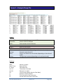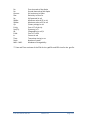
1
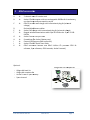
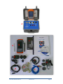
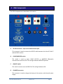
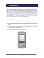
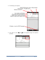
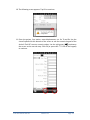
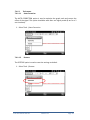
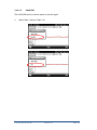
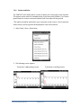
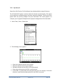
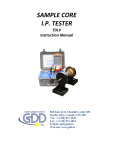
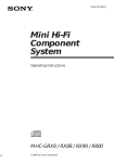
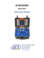
IP RECEIVER
Model GRx2
Instruction Manual
860 boul. de la Chaudière, suite 200
Québec (Qc), Canada, G1X 4B7
Tel.: +1 (41) 877-4249
Fax: +1 (418) 877-4054
E-Mail: [email protected]
Web site: www.gdd.ca
Table of contents
1
Introduction.....................................................................................................4
2
GRx2 accessories ..............................................................................................5
3
GRx2 components ............................................................................................7
4
Power ..............................................................................................................9
5
Quick start guide ............................................................................................ 11
6
RS232/Bluetooth communication................................................................... 20
7
Tools menu .................................................................................................... 21
7.1
Config option ............................................................................................. 23
7.1.1
Setup .................................................................................................. 23
7.1.2
Position .............................................................................................. 25
7.1.3
Windows ............................................................................................ 27
7.2
Special option ............................................................................................ 32
7.2.1
Reinit ................................................................................................. 32
7.2.2
Simulation .......................................................................................... 33
7.2.3
Signal Processing Options ................................................................... 37
7.2.4
Battery type ....................................................................................... 38
7.3
Hotkeys ..................................................................................................... 40
7.4
Show option .............................................................................................. 41
7.4.1
Signal ................................................................................................. 41
7.4.1.1
Tools menu ....................................................................................... 43
7.4.1.1.1
Auto Correction .......................................................................... 43
7.4.1.1.2
Restore ........................................................................................ 43
7.4.1.1.3
PAUSE/GO ................................................................................... 44
7.4.2
Contact and Noise .............................................................................. 45
7.4.3
Vp and Cycle ....................................................................................... 46
7.4.4
Show M and errM ............................................................................... 47
7.4.5
Decay Curve ....................................................................................... 48
7.4.6
Show Windows ................................................................................... 49
7.4.7
Show Sp ............................................................................................. 50
7.5
Raw Data option ........................................................................................ 51
7.5.1
Check GPS .......................................................................................... 51
7.5.2
Start Recording (raw data) .................................................................. 55
7.6
Memory option .......................................................................................... 57
7.6.1
Display Reading .................................................................................. 57
7.6.2
History ............................................................................................... 59
7.6.3
Back Mem .......................................................................................... 60
7.6.4
Clear Mem .......................................................................................... 61
7.6.5
Save File ............................................................................................. 63
7.7
About option ............................................................................................. 65
8
Transferring data ........................................................................................... 66
8.1
ActiveSync installation and settings............................................................ 67
8.2
Windows Mobile Device Center installation and settings ............................ 68
Instrumentation GDD inc.
2014-05-13
Page 2
8.3
Connecting the Archer2 Field PC to a desktop PC ........................................ 70
8.4
Transferring file(s) from the Archer2 Field PC to a desktop PC ..................... 71
9
Bluetooth configuration ................................................................................. 73
9.1
Bluetooth partnership configuration .......................................................... 73
10 GDD Rx software update ................................................................................ 78
11 Troubleshooting............................................................................................. 82
12 Technical help ................................................................................................ 85
13 Specifications................................................................................................. 86
13.1 General specifications ................................................................................ 86
13.2 Technical specifications .............................................................................. 86
Annex 1 – Geometrical parameters ........................................................................ 88
Annex 2 – Field survey setup .................................................................................. 93
Annex 3 – Example Dump File .............................................................................. 112
Instrumentation GDD inc.
2014-05-13
Page 3
1
Introduction
The GDD IP Receiver is a new compact, low consumption unit designed for resistivity
measurements. It features high capabilities allowing it to work on any field conditions.
It can be configured in multi-pole or multi-dipole reception.
The receiver uses a PDA handheld PC to process data acquisition. A WVGA LCD TFT
display allows monitoring the results live on the field. The operating system is Windows
Embedded Handheld 6.3 and the software can easily be updated via internet.
Caracteristics:
•
Reception poles/dipoles: 2 poles/dipoles, expandable to 32, for dipole-dipole,
pole-dipole or pole-pole arrays.
•
Programmable windows: The GRx2 offers twenty fully programmable windows
for a higher flexibility in the definition of the IP decay curve.
•
User modes available: Arithmetic, logarithmic, semi-logarithmic, Cole-Cole, IPR12 and user define.
•
IP display: Chargeability values, Resistivity and IP decay curves can be displayed
in real time thanks to the VGA screen. Before data acquisition, the GRx2 can be
used as a one channel graphic display for monitoring the noise level and checking
the primary voltage waveform through a continuous display process.
•
Internal memory: Over 64 000 readings can be stored in the internal memory of
the PDA. Each reading includes the full set of parameters characterizing
measurements. Data are stored on flash type memory and can not be lost even if
the battery of the PDA is totally discharged or absent.
Instrumentation GDD inc.
2014-05-13
Page 4
2
GRx2 accessories
A
B
1x
1x
C
1x
D
E
F
1x
1x
G
H
I
J
K
1x
1x
1x
1x
1x
2 channels GRx2 IP receiver unit
Archer2 Field computer with one rechargeable 10600mAh Li
Li--Ion battery,
one hand strap and one capacitive stylus
GRx2 IP receiver wall charger with international plug kit (universal
voltage)
Red and black banana cables
Archer2 AC charger with international plug kit (universal voltage)
Rugged serial communication cable 9 pos D-SUB female - 9 pos. D-SUB
female
Archer2 micro USB sync cable
Screwdriver (for Archer2 battery cap)
External GPS antenna (SMA connector)
Archer2 Field PC Quick Start Guide
GRx2 Instruction Manual and GRx2 Utilities CD (contains GDD Rx
software, Sync softwares, GRx2 manuals, Archer2 manual)
1
Optional:
Allegro Mx PDA complete kit
-
Allegro Mx basic kit
Allegro Mx complete kit
Archer2 Field PC spare battery
Spare channel
Instrumentation GDD inc.
2014-05-13
Page 5
A
J
K
B
H
E
I
C
G
Instrumentation GDD inc.
F
D
2014-05-13
Page 6
3 GRx2 components
The GRx2 components are described in this section.
A
B
E
C
D
F
G
A - RS-232 connector - 9 pin serial communication port
This connector is used to connect the RS-232 cable between the Archer2 Field PC
and the GRx2 receiver.
B - CABLE/WIRELESS switch
This switch is used to select CABLE (RS-232) or WIRELESS (Bluetooth)
communication with the PDA. The red light indicates WIRELESS position.
C - ON/OFF switch
This switch is used to turn the GRx2 ON. The red light indicates ON.
D - CHARGER connector
This connector is used to charge the battery of the receiver with the wall power
supply.
Instrumentation GDD inc.
2014-05-13
Page 7
E
- REF terminal
This terminal is the infinite electrode in pole configuration. In dipole
configuration, this terminal is the first electrode in differential with the second
electrode.
F
- NUMBERED terminals
These terminals are referenced to the Ref terminal (infinity in pole configuration).
In dipole configuration, the numbered terminals are differential terminals.
G - SELF-TEST terminal
This terminal is used to perform a self test.
H
H - GPS connector (SMA)
This connector is used to connect an external GPS antenna (SMA).
Instrumentation GDD inc.
2014-05-13
Page 8
4
Power
GDD’s GRx2 I.P. Receiver is powered by internal rechargeable lithium-ion batteries.
Here are a few tips for using and storing your lithium-ion powered receiver:
Usage
•
•
•
•
•
•
•
Using a different battery power supply than the one supplied by GDD could
damage the batteries and the receiver.
The connector labelled CHARGER is used only to recharge the internal
batteries.
Do not replace the receiver internal batteries without the authorization and
advice from GDD’s technicians.
The total operating time of the receiver will depend on the environmental
conditions. Using the receiver in very cold weather (-200C to –400C) will lower
the operating time.
The receiver will turn itself off when the batteries reach a critical level.
To extend battery life, avoid frequent full discharge and charge more often
between uses.
The power level of the batteries and the charging status appear on the main
screen of the Archer2 Field PC when using the GDD Rx program.
Power level
Charging
Instrumentation GDD inc.
2014-05-13
Page 9
Charge completed
Storage
•
•
•
To avoid permanent capacity loss, store the receiver and the external battery
pack at 40% charge.
Store the receiver and the external battery pack in a cool and dry place.
If stored for several months, check the batteries charge level every six months
and recharge them up to 50% if they are below 30% charge.
Never store fully charged or completely discharged Lithium-Ion batteries for an
extended period of time.
Instrumentation GDD inc.
2014-05-13
Page 10
5 Quick start guide
Important note : Using a finger may still be the preferred option for projected
capacitive screen technology, but we understand a stylus may also be necessary (like
when it’s cold). The way you hold a capacitive stylus really impacts how it works. To
register a point, it is like the screen is taking a sample from which to calculate the
position. It then snaps to the closest line on a grid. If you hold a capacitive stylus at an
angle, it registers less area and does not calculate your true position as well. For best
results on a capacitive screen like the Archer2, hold the stylus as perpendicular to the
screen or straight up as you can. In this section, you will see some tips to use the
Archer2 keypad to perform some actions of the GDD Rx program.
1. Connect electrodes into terminals.
2. Turn ON the IP receiver using the ON/OFF switch on the GRx2 panel.
3. Select the communication mode using the CABLE/WIRELESS switch on the GRx2
panel.
4. Connect the RS-232 cable between the Archer2 Field PC and the GRx2 RS-232
connector (CABLE communication only).
5. Turn ON the Archer2 Field PC with the ON/OFF key.
Instrumentation GDD inc.
2014-05-13
Page 11
6. Tap on the GDD Rx program icon in the Favorites bar of the Home Page.
Title bar
Dashboard
Favorites
Tile bar
7. Select the communication mode: RS-232 (CABLE) or BLUETOOTH (WIRELESS).
You can move back and forth between the different actions using the tab
button ( ) of the keypad. Press Enter button ( ) of the keypad to perform
the highlighted action.
Instrumentation GDD inc.
2014-05-13
Page 12
8. The following screen appears.
START/STOP button: Start or Stop readings
TOOLS button : Rx option menu
Number of channels
Line number and direction
Transmitter and receiver position
Trigger channel count and voltage
Memory number and Rx battery level
OK button : close the GDD Rx program
9. Click START (or press
procedure.
Instrumentation GDD inc.
, and
on the keypad) to begin the acquisition
2014-05-13
Page 13
10. The following screen appears. Tap OK to continue.
11. Enter the project, line, station, move displacement, etc. for Tx and Rx. Use the
virtual keyboard at the bottom of the screen or use the numeric keypad of the
Archer2 Field PC to enter numeric values. Use the tab button ( ) to advance
the cursor to the next tab stop. Click OK (or press shift +5 OK on the keypad)
to continue.
Instrumentation GDD inc.
2014-05-13
Page 14
12. Verify if the positions are correct and click OK (or press shift +5 OK on the
keypad) to continue.
Displacement
enabled
Go to previous
station
Go to next
station
Go to previous
line
Go to
next line
Note : F1 to F4 shortcut key are not available with the Archer2 Field PC.
13. The Contact and Noise graph appears. If the values displayed are normal, click
OK (or press shift +5 OK on the keypad) to close the window.
Instrumentation GDD inc.
2014-05-13
Page 15
14. Click NEXT (or press Tab
, and Enter
on the keypad) to continue.
*Note: If all stations show an INFINITE contact, the reference electrode might
be disconnected.
15. Enter the transmitter current and click CONFIRM to start the readings.
16. The following screens appear.
Instrumentation GDD inc.
2014-05-13
Page 16
17. Click STOP or wait until the end of the acquisition to stop the readings and save
the data.
18. Click YES to confirm the operation.
19. Click YES to save readings into the memory.
Instrumentation GDD inc.
2014-05-13
Page 17
20. Check the REDO POSITIONS option to change the transmitter or receiver
position.
Change the current value if it has changed and click CONFIRM to save the
current value.
20.1. If the REDO POSITIONS option is checked, enter the transmitter and
receiver position and click OK.
*Each position can be changed individually or moved by clicking Next or
Prev.
Instrumentation GDD inc.
2014-05-13
Page 18
Once your acquisition is finished, use Left and Right arrow buttons (shift
+
4
or 6
) to compare your current data with that of your previous acquisitions.
Use the Up and Down arrows to see all the channels. By clicking on Start, the
program will automatically come back to the last acquisition and will start a
new acquisition procedure.
21. Repeat steps 9 through 19 to take another set of readings.
Instrumentation GDD inc.
2014-05-13
Page 19
6
RS232/Bluetooth communication
1. Select the “RS-232” communication mode to use the GRx2 with a serial
communication cable.
2. Select the “BLUETOOTH” communication mode to use the GRx2 with a wireless
connection.
3. The following screen appears and you are ready to begin.
In Bluetooth mode, if a “COM Error” message appears, see Section 12 –
Troubleshooting.
Instrumentation GDD inc.
2014-05-13
Page 20
7
Tools menu
Click TOOLS to select one of the following options or press , and
on the keypad
to open the Tools menu, and press shift +
or
to highlight the different
options. Then press
to open the highlighted option.
Config
Use the CONFIG option to change:
• Staking parameters
• Electrode array
• Active channel
• Trigger channel
• Line number and position
• Transmitter and receiver position
• Signal timing
• Mode
Special
Use the SPECIAL option to:
• Re-init the GRx2
• Test the GRx2 with the internal simulator
• Set signal processing options
• Select battery type (if not automatically detected)
Hotkeys
Use the HOTKEYS option to display the shortcut keys menu
Instrumentation GDD inc.
2014-05-13
Page 21
Show
Use the SHOW option to display:
• Signal graph
• Contact and Noise monitor graph
• Vp and Cycle synchronization graph
• Decay curve
• Windows chargeability
• SP (self potential)
Memory
Use the MEMORY option to:
• See the History
• Recall the previous memory
• Clear the memory
• Save data in a file
About
Use the ABOUT option to display GDD Rx software version number.
Instrumentation GDD inc.
2014-05-13
Page 22
7.1 Config option
7.1.1 Setup
The SETUP option is used to set the electrode arrays, the active channel(s) and the
trigger channel.
1. Select Tools | Config | Setup, the following window appears.
2. Select the electrode arrays configuration.
•
Dipole-Dipole (1/32)
•
Pole-Dipole (1/32)
•
Pole-Pole (1/32)
•
Gradient (1/32)
•
Wenner
•
Schlumberger
Dipole-Dipole (2/16), Dipole-Dipole (4/8), Pole-Dipole (2/16), Pole-Dipole (4/8) and
other modes (2/16) or (4/8) are used with a 16 or 32 channels receiver only.
Instrumentation GDD inc.
2014-05-13
Page 23
3. Check the active channel(s). Tap on the
checkbox to select all channels or
tap on the
checkbox to unselect all channels.
4. Select the trigger channel, this channel is used for the synchronization process.
Instrumentation GDD inc.
2014-05-13
Page 24
7.1.2 Position
The POSITION tab is used to set these parameters: the Tx line number, the Rx line
number, the line direction, the transmitter position (Tx1 and Tx2), the receiver
position, the separation, the transmitter movement offset and receiver movement
offset.
1. Select Tools | Config | Position
2. Enter line number and select line direction. Use the keyboard at the bottom of
the screen or use the numeric keypad of the Archer2 Field PC.
A negative number cannot be entered for line; the labels N, S, E and W are used
to define direction.
Instrumentation GDD inc.
2014-05-13
Page 25
3. Enter the transmitter and receiver first electrode position.
A negative number is used to define South and West direction.
4. Enter the separation between electrodes of the receiver.
A negative number is used to define South and West direction.
5. Enter the transmitter and receiver electrodes moving distance.
A negative number is used to define South or West direction.
Instrumentation GDD inc.
2014-05-13
Page 26
7.1.3 Windows
The WINDOWS option is used to set the signal timing and the mode.
1. Select Tools | Config | Windows
2. Select the maximum number of stacks.
3. Select the signal timing.
Instrumentation GDD inc.
2014-05-13
Page 27
4. Select the mode (windows time definition).
•
Arithmetic
Windows: 20
Delay (ms): 240
Timin g (ms): 2000
80, 80, 80, 80, 80, 80, 80, 80, 80, 80,
80, 80, 80, 80, 80, 80, 80, 80, 80, 80
•
Semi logarithmic
Windows: 20
Delay (ms): 40
Timing (ms): 2000
40, 40, 40, 40, 40, 40, 80, 80, 80, 80,
80, 80, 80, 160, 160, 160, 160, 160, 160, 160
•
Logarithmic
Windows: 4
Delay (ms): 160
Timing (ms): 2000
120, 220, 420, 820
•
Cole
Windows: 20
Delay (ms): 20
Timing (ms): 2000
20, 30, 30, 30, 40, 40, 50, 60, 70, 80,
90, 100, 110, 120, 130, 140, 150, 160, 180, 200
Instrumentation GDD inc.
2014-05-13
Page 28
•
User defined
Windows: between 1 and 20
Delay (ms): user defined
Timing (ms): user defined
In the USER mode, you can load settings you have saved before, or you can create
new settings.
Click YES to load your settings from a previously saved file. This window will appear.
In this dialog box, select your file. The Windows window appears automatically.
Click OK. The saved values will be loaded in the User defined mode.
OR
Instrumentation GDD inc.
2014-05-13
Page 29
Click NO to manually enter the delay and window(s) width.
Click OK when your settings are configured.
Click YES to save your new settings.
Enter your filename and the location where you want to save your file.
The User defined settings will be saved so you can reload them in the
Archer2 Field PC later.
Instrumentation GDD inc.
2014-05-13
Page 30
Click NO if you do not want to save your User defined settings in a file.
In all cases, you will be brought back to this display and the settings you have entered
in the User defined window will be loaded into the Archer2 Field PC.
Instrumentation GDD inc.
2014-05-13
Page 31
7.2 Special option
7.2.1 Reinit
The REINIT option is used to reset GRx2 communication with the Archer2 Field PC.
This option is useful when the Bluetooth communication is lost.
1. Select Tools | Special | Reinit
2. Click YES to reinitialize the GRx2.
Instrumentation GDD inc.
2014-05-13
Page 32
7.2.2 Simulation
The SIMULATION option is used to perform a self test with the internal waveform
generator (you need to select the Pole-Pole configuration to use this option).
1. Short the SELF-TEST terminal with the channel(s) you want to test. The picture
below shows a self-test with the two channels.
Instrumentation GDD inc.
2014-05-13
Page 33
2.
Turn ON the receiver.
3.
Select Tools | Config | Setup
4.
Select the Pole-Pole (1/32) array configuration.
Instrumentation GDD inc.
2014-05-13
Page 34
5.
Check the channel(s) you want to test. Click Ok.
6.
Select Tools | Special | Simulation
7.
8.
9.
Enter the waveform timing (default = 2000ms).
Enter the primary voltage (default = 500mV).
Enter the chargeability (default = 0).
Instrumentation GDD inc.
2014-05-13
Page 35
10.
Click on CONFIRM. The output signal of the self-test electrode will be activated
only once you have click on CONFIRM.
11.
Click START to begin the acquisition process.
12.
If you want to disable the self-test output signal, go to Simulation window and
enter 0mV in the Voltage field.
Instrumentation GDD inc.
2014-05-13
Page 36
7.2.3 Signal Processing Options
The SIGNAL PROCESSING OPTIONS are used to disable the default gain and offset
settings. When offset and gains are applied, the signal to noise ratio is improved.
1.
Select TOOLS | Special | Signal Processing Options
2. Check the checkboxes of the settings you want to disable and click CONFIRM.
Note that the gains and offsets are enabled (applied) every time you start the GDD Rx
program again even if you disabled them the last time you used them.
Instrumentation GDD inc.
2014-05-13
Page 37
7.2.4 Battery type
With GRx8-32 firmware version 2.5.5 or higher, the GDD Rx program detects the type
of batteries in the receiver automatically. It cannot be done with GRx2.
Select Tools | About
If a battery type is detected, the information will appear in the About pop-up window.
If the GDD Rx program cannot detect the battery type (GRx8-32 firmware 2.5.4 or
earlier, or GRx2 receiver), the About pop-up window will indicate Battery Type: not
detected.
In which case, it is possible to select the battery type manually.
Select Tools | Special | Battery Type
Instrumentation GDD inc.
2014-05-13
Page 38
Select the type of batteries in your receiver. All GRx2 receivers have Li-Ion batteries.
If you select the wrong battery type, the battery level indicated in the main window of
the GDD Rx program will be slightly different from the actual value.
Instrumentation GDD inc.
2014-05-13
Page 39
7.3 Hotkeys
The HOTKEYS option is used to display the shortcut keys menu. This option is
available with the Allegro Field PC only.
1. Select Tools | Show | Hotkeys
2. The following screen appears.
Use the shortcut keys to navigate quickly between the different options.
Instrumentation GDD inc.
2014-05-13
Page 40
7.4 Show option
7.4.1 Signal
The SIGNAL option is used to display the signal graph of a selected channel.
1. Select Tools | Show | Show Signal
2. The following screen appears.
Channel Selection
Time Scale
Offset Voltage Scale
Graph TOOLS menu
Increase Voltage Scale
Increase Offset Voltage
Decrease Offset Scale
Decrease Voltage Scale
Close graph button
Instrumentation GDD inc.
2014-05-13
Page 41
3. Select offset voltage scale.
4. Select time scale.
5. Select display channel
Instrumentation GDD inc.
2014-05-13
Page 42
7.4.1.1
Tools menu
7.4.1.1.1
Auto Correction
The AUTO CORRECTION option is used to optimize the graph scale and correct the
offset of the signal. This option should be used after one signal period (8 sec for a 2
sec time base).
1. Select Tools | Auto Correction
7.4.1.1.2
Restore
The RESTORE option is used to reset the settings to default.
1. Select Tools | Restore
Instrumentation GDD inc.
2014-05-13
Page 43
7.4.1.1.3
PAUSE/GO
The PAUSE/GO option is used to pause or play the signal.
1.
Select Tools | Pause or Tools | Go
Instrumentation GDD inc.
2014-05-13
Page 44
7.4.2 Contact and Noise
The CONTACT AND NOISE option is used to display the noise graph of all channels.
This option can be useful for troubleshooting if you have noise problem. The Contact
graph shows the contact resistance between your electrodes and the ground.
*This option should be used before your transmitter sends current. If the transmitter
sends current, the Vp signal will be displayed for each active channel.
1. Select Tools | Show | Show Noise
2. The following screen appears.
Transmitter is not sending current
Instrumentation GDD inc.
2014-05-13
Transmitter is sending current
Page 45
7.4.3 Vp and Cycle
Steps 14 to 16 of Section 5 of this Manual must be done before using this feature.
The VP AND CYCLE option is used to show the channel synchronization. This option
can be useful for troubleshooting if you have connection problem. The VP part of the
graph shows the primary voltage of all your electrodes. The current graph is an
example; your VP graph will depend on the physical configuration of the electrodes.
1. Select Tools | Show | Show Cycle
2. The following screen appears.
•
•
•
•
•
Green line indicates that this Vp is positive.
Blue line indicates that this Vp is negative.
Red dots indicate that the GRx2 is not synchronized.
Green dots indicate that the GRx2 is synchronized.
If the GRx2 is synchronized and the green dots are not moving in the same
direction, check the electrodes position on the GRx2 front panel.
Instrumentation GDD inc.
2014-05-13
Page 46
7.4.4 Show M and errM
Steps 14 to 16 of Section 5 of this Manual must be done before using this feature.
The Show M and errM option is used to display the chargeability and the error in
chargeability for each channel.
1. Select Tools | Show | M and errM
2. The following screen appears.
Instrumentation GDD inc.
2014-05-13
Page 47
7.4.5 Decay Curve
Steps 14 to 16 of Section 5 of this Manual must be done before using this feature.
The Decay Curve option is used to display the decay graph of a selected channel.
1. Select Tools | Show | Show Decay
2. The following screen appears.
3. Select the displayed channel.
Instrumentation GDD inc.
2014-05-13
Page 48
7.4.6 Show Windows
Steps 14 to 16 of Section 5 of this Manual must be done before using this feature.
The Show Windows option is used to display the windows chargeability of each
channel.
1. Select Tools | Show | Show Windows (1-8 ch)
2. The following screen appears.
Channel number
Chargeability value
Window number
Instrumentation GDD inc.
2014-05-13
Page 49
7.4.7 Show Sp
Steps 14 to 16 of Section 5 of this Manual must be done before using this feature.
The SHOW SP option is used to display the self potential (SP) in mV of each channel.
3. Select Tools | Show | Show SP
4. The following screen appears.
Self potential
value
Channel number
Instrumentation GDD inc.
2014-05-13
Page 50
7.5
Raw Data option
7.5.1 Check GPS
To use the GPS function, your receiver must be equipped with an internal GPS
module. This GPS module is designed for use with applications that require accurate
time.
The Check GPS option is used to verify if a satellite is being tracked by the GPS
module.
Connect an external antenna (SMA) to the GPS connector of the GRx2 receiver for
more efficiency.
After turning on the GRx2 receiver, it can take up to 2 or 3 minutes for the GPS
receiver to track and synchronize with a satellite.
Select Tools | Raw Data | Check GPS
Instrumentation GDD inc.
2014-05-13
Page 51
If the GPS module is not synchronized with a satellite, the following window will
appear.
Once the GPS module is synchronized with a satellite, the following window should
appear.
If the GPS signal is lost, the time synchronization will be kept for 30 minutes. In that
case, the following window should appear :
Instrumentation GDD inc.
2014-05-13
Page 52
This window allows you to verify if the GPS works properly. You can close this
window and continue to work normally with your GRx8-32 receiver. You can
occasionally verify if the GPS is still tracking the satellite.
The GPS timestamps will appear in the .gps file (see Section 7.6.5 to to create a .gps
file). The data in this file is the same than that of the .gdd file except for the GPS
timestamp (the time in the .gdd file comes from the PDA).
Example of a .gps file
If there is a GPS synchronization, the column GPS will show YES as shown on the
picture above.
If the GPS signal is lost, the synchronization will be kept for 30 minutes. In that case,
the Date and Hour will continue to increase following the GPS time but the GPS
column will show NO as shown on the picture below.
If there is no GPS synchronization or if the GPS signal has been lost for more than 30
minutes, the Date and Hour will be replaced by NO GPS TIME.
The GPS timestamps will also appear in the fullwave file (see Section 7.6.5 to create
a fullwave file) or in the raw data file (see Section 7.5.2 to use raw data option).
Instrumentation GDD inc.
2014-05-13
Page 53
Example of a fullwave file with GPS timestamps
Example of a raw data file with GPS timestamps
As for the .gps file, if there is no GPS synchronization or if the GPS signal has been
lost for more than 30 minutes, the Date and Hour will be replaced by NO GPS TIME
in the .fullwave and .rdf files.
Take note that for some reasons, such as weak signal areas, the GPS module will not
be able to track and synchronize with a satellite.
Instrumentation GDD inc.
2014-05-13
Page 54
7.5.2 Start Recording (raw data)
This option is used to record raw data without any synchronization with a
transmitter signal. This can be useful to record the telluric or noise from the ground.
The receiver will record a reading every 20 ms. Thanks to the GPS module, each
recorded reading will be accurately time stamped. Your receiver must be equipped
with an internal GPS module to use GPS with the raw data function.
1. Make sure that channel 1 is connected to the ground.
2. If you want to verify the GPS time, select Tools | Raw Data |Check GPS (see
Section 7.5.1 for more details).
If you see No GPS Time, either the internal GPS module cannot receive any data from a
satellite, or your receiver does not have this option.
3. To begin the data acquisition, select Tools | Raw Data | Start recording.
Instrumentation GDD inc.
2014-05-13
Page 55
4. You will be prompted to name your file.
5. The following icon will appear and data will be recorded until you stop the
acquisition by selecting Tools | Raw data | Stop recording.
The extension of the file created with your raw data is ‘.rdf’.
Example of a raw data file with GPS timestamps
Instrumentation GDD inc.
2014-05-13
Page 56
7.6 Memory option
7.6.1 Display Reading
The Display Reading option displays a particular reading on the PDA as the operator
would see it in the field even if no receiver is connected to the PDA.
The following window will appear. The number in the Reading Number: field is always
the Memory number of the latest reading taken. Enter the number of the reading you
want to see. Click on CONFIRM.
Instrumentation GDD inc.
2014-05-13
Page 57
Select the chargeability windows you want to see and click CONFIRM.
The selected readings appear.
Use Left and Right arrow buttons (shift
+ 4
or 6
) to compare your current data
with that of your previous acquisitions. Use the Up and Down arrows to see all the
channels.
Keep in mind that there is no indication of which reading is monitored on the PDA
display. At this point, it is possible to use the show menu to display some graphics or
values of the channels.
Instrumentation GDD inc.
2014-05-13
Page 58
7.6.2 History
The History option is used to display all the data accumulated in the memory.
You will have to use the scroll bar to see all the information available. Click Next to go
to the next page. The three following slides show all the information displayed by the
history.
Instrumentation GDD inc.
2014-05-13
Page 59
7.6.3 Back Mem
The Back Mem option is used to clear the last readings of the memory one by one.
1. Select Tools | Memory | Back Mem
2. Click Yes to clear the last readings.
Instrumentation GDD inc.
2014-05-13
Page 60
7.6.4 Clear Mem
The Clear Mem option is used to clear all the readings of the memory.
1. Select Tools | Memory | Clear Mem
2. Click Yes to confirm the operation.
3. Enter 9999 in the text box and click CONFIRM to clear all the readings of the
memory.
Instrumentation GDD inc.
2014-05-13
Page 61
4. A message will follow to confirm your operation.
Instrumentation GDD inc.
2014-05-13
Page 62
7.6.5 Save File
The Save File option is used to save the readings into a file.
1. Select Tools | Memory | Save File
2. Select the output file format available according to your electrode configuration
(only one output file format could be available). A GDD Generic file is always
created even if you choose another format.
Instrumentation GDD inc.
2014-05-13
Page 63
3. Select FULLWAVE if you want to create the fullwave file and click CONFIRM.
4. Enter the file name and click Save (the saving operation can take several minutes).
5. The following screen appears; click OK to close the pop up dialog box.
Instrumentation GDD inc.
2014-05-13
Page 64
7.7
About option
The About option is used to display the software version number.
1. Select Tools | About
2. The following screen appears.
*See Section 7.2.4 for more information about Battery Type.
Instrumentation GDD inc.
2014-05-13
Page 65
8
Transferring data
In order to establish communication between the Archer2 Field PC and a desktop PC,
you need to install the appropriate synchronisation software.
Windows 7 or Vista 64 bits users will require Windows Mobile 64 bits while Windows 7
or Vista 32 bits users will need to install Windows Mobile 32 bits.
Install ActiveSync if you run Windows XP or earlier.
All three software are available on the CD supplied by GDD.
Instrumentation GDD inc.
2014-05-13
Page 66
8.1
ActiveSync installation and settings
1. Once ActiveSync is installed, a gray icon will appear in the bottom right corner of
your desktop PC screen.
2. Right click on the ActiveSync icon to open the following menu and select
Connection Settings...
3. Check Allow USB connection with this desktop computer.
Instrumentation GDD inc.
2014-05-13
Page 67
8.2
Windows Mobile Device Center installation and settings
1. Once Windows Mobile Device Center 32 or 64 bits is installed, click the Windows Start
Menu icon and then click All Programs to display all installed programs. Click Windows
mobile Device Center to launch the application.
2. Under Mobile Device Settings option, click on Connection settings.
Instrumentation GDD inc.
2014-05-13
Page 68
3. Check Allow USB connections
Instrumentation GDD inc.
2014-05-13
Page 69
8.3
Connecting the Archer2 Field PC to a desktop PC
1. Turn the PDA ON
2. Connect the USB cable between the Archer2 Field PC and your desktop computer.
3. The desktop ActiveSync (or Windows Mobile Device Center) icon is now green.
4. A small PCLink icon appears on the Archer2 title bar.
Instrumentation GDD inc.
2014-05-13
Page 70
8.4
Transferring file(s) from the Archer2 Field PC to a desktop PC
1. Double click on the My Computer icon on your desktop PC.
2. Double click on the Mobile Device's icon.
3. Double click on the Main folder icon.
4. Double click on the My Documents folder.
Instrumentation GDD inc.
2014-05-13
Page 71
5. Use the drag and drop or cut, copy and paste functions to move file(s) between your
Archer2 and your desktop PC.
The data file is named: File_Name.gdd
6. Open the saved files with Notepad or Excel.
Instrumentation GDD inc.
2014-05-13
Page 72
9
Bluetooth configuration
9.1 Bluetooth partnership configuration
1. Make sure that the Bluetooth is on. If the Bluetooth icon in the Dashboard of the
Archer2 Field PC is gray, click on the icon to enable it.
2.
Click on the Bluetooth icon in the Title bar.
3.
Click on Add new device.
Instrumentation GDD inc.
2014-05-13
Page 73
4.
The program searches for Bluetooth Devices. This step may take a few seconds.
5.
Select the GRx2’s name (RxXXXX) and click on Next.
6.
Enter the passcode 1234 and click Next. Open the virtual keyboard or use the
numeric keypad of the Archer2 Field PC.
Instrumentation GDD inc.
2014-05-13
Page 74
7. This message may appear for a few seconds. Click on Advanced or wait until it
disappears and click on your GRx2 name.
8. Check Serial Port and click on Save.
9.
Select COM Ports.
Instrumentation GDD inc.
2014-05-13
Page 75
10. Click on New Outgoing Port.
11. Select your GRx2’s name and click on Next.
12. Open the Port menu.
Instrumentation GDD inc.
2014-05-13
Page 76
13. Select COM9 and click Finish.
14. The name of your GRx2 receiver should appear with the COM9 tag. Click on the
OK button to close the window.
Instrumentation GDD inc.
2014-05-13
Page 77
10 GDD Rx software update
1. Connect the USB cable between the Archer2 Field PC and your desktop computer.
2. Double click on the My Computer icon on your PC's desktop .
3. Double click on the Mobile Device icon.
Instrumentation GDD inc.
2014-05-13
Page 78
4. Double click on the Main folder icon.
5. Double click on the Program Files icon.
6. The GDD Rx program files are located in the GDD folder.
Instrumentation GDD inc.
2014-05-13
Page 79
7. Rename the old version of the folder to keep a backup on your Archer2 Field PC.
Right click on the GDD folder and select Rename.
8. Rename the folder (example: GDD_ Old_Version).
9. Right click on the Program Files window and create a new GDD folder.
Instrumentation GDD inc.
2014-05-13
Page 80
10. Use the drag and drop or the copy and paste functions to move the new GDD Rx
software files from your computer to the GDD folder of your Archer2 Field PC.
Instrumentation GDD inc.
2014-05-13
Page 81
11 Troubleshooting
This section explains some problems that could occur when using the GDD Rx2 as
well as proposed solutions.
For any issues regarding the Archer2 Field PC other than these related to the GDD
program, please refer to the user manual of the Archer2 Field PC available on the
utilities CD provided by GDD.
Problem :
The message: ‘GDD Rx – No Receiver’ is shown in the program bar of the GDD Rx
program. It stays on the bar even if the Archer2 Field PC is connected to the
receiver.
Answer
Check that the receiver’s On-Off switch is at On and that the LED is on.
Verify that the receiver’s batteries are powered enough and not within the
critical threshold limit.
In Cable mode, verify that the cable is plugged correctly on the receiver and on
the Archer2 Field PC.
In Bluetooth mode, close the GDD Rx program and try to start it again. If the
program does not detect the receiver in Bluetooth mode, open the program in
RS232 mode and save all your data. When your data are saved, reset your
Archer2 Field PC by pressing and holding the Power button. The following
message appears. Select Reset.
Instrumentation GDD inc.
2014-05-13
Page 82
Problem :
In Bluetooth mode, the following message appears.
Answer :
Make sure that the Cable / Wireless switch is on Wireless position and that the
receiver is turned on.
Look at the Bluetooth icon in the Dashboard:
If it is gray, click on the icon to enable it.
Try to start the SCIP software in Bluetooth mode again.
Instrumentation GDD inc.
2014-05-13
Page 83
See Section 9.1 to know how to verify if a partnership has been established
between your receiver and your Archer2 Field PC.
Reset your Archer2 Field PC by pressing and holding the Power button. The
following message appears. Select Reset.
Problem :
The message “Battery Error” appears on the main screen of the GDD Rx program on
the Archer2 PDA.
Answer :
A problem occurs during the receiver battery charging : over voltage, charging
under 0°C or over 45°C, charging time too long, defective battery, etc.
Try to disconnect and connect the AC charger.
Problem :
A red icon appears during the acquisition process.
!!!
Answer :
Click on the red icon to see what happens.
This alarm usually means that the Vp is saturated. The channels of the receiver
are protected against voltage up to 500V but they can read a Vp of up to 15V
only.
Instrumentation GDD inc.
2014-05-13
Page 84
12 Technical help
If you encounter a problem not described in this manual, do not hesitate to contact
Instrumentation GDD Inc. for help at:
Tel.:
(418) 877-4249
Fax:
(418) 877-4054
Toll free line:
1 877 977-4249
e-mail:
[email protected]
Emergency out of business hours:
Pierre Gaucher:
Régis Desbiens:
Home phone:
Cell phone:
Home phone:
Cell phone:
(418) 657-5870
(418) 261-5552
(418) 658-8539
(418) 570-3408
Any GDD IP Receiver that breaks down while under warranty or service will be
replaced free of charge upon request for the duration of repairs, except for shipping
fees. This service is subject to instrument availability but we have been able to
honour this commitment up to now.
Printed in Canada in April 2009.
Instrumentation GDD inc.
VER0-3.12
2014-05-13
Page 85
13 Specifications
13.1
General specifications
Number of channels:
2
Size:
23.2 x 19.2 x 11.1 cm (9.12 x 7.56 x 4.37 in)
Weight:
1.5 kg (3.2 lbs)
Enclosure:
Heavy-duty Pelican case,
environmentally sealed
Communication options:
RS-232 (serial) and Bluetooth
class I to communicate with a
PDA
USB for data download
Power supply:
10.8V 3.4Ah rechargeable IonLithium internal battery
Temperature range:
-40 to +60oC (-49 to +140oF)
Humidity range:
Waterproof
13.2
Technical specifications
Survey capabilities:
Resistivity and Time domain IP
Twenty chargeability windows:
Arithmetic, logarithmic,
semi-logarithmic, Cole-Cole and
user defined
Synchronization:
Automatic re-synchronization
Process on primary voltage
Signal
Noise reduction:
Automatic stacking number
Computation:
Apparent resistivity,
chargeability, standard
deviation, and % of symmetrical Vp
Ground Resistance:
Up to 1.5 MΩ
Signal waveform:
Time domain (ON+, OFF, ON-, OFF)
Time base:
0.5, 1, 2, 4 and 8 seconds
Input impedance:
5 GΩ
Instrumentation GDD inc.
2014-05-13
Page 86
Primary voltage range:
±10 uV to ±15 V for any channel
Protection:
500V (on each channel)
Input:
True differential for common-mode
rejection in dipole configuration
Voltage measurement:
Resolution 1 µV
Accuracy 0.5%
Chargeability measurement:
Accuracy 0.8%
SP offset adjustment:
± 5 V, automatic compensation
through linear drift correction per
steps of 150 µV
Filter:
Eight-pole Bessel low-pass 15 Hz,
notch filter 50 Hz and 60 Hz
PDA menu-driven software / simple to use
Real-time data and automatic data stacking
Screen-graphics: decay curves, resistivity, chargeability, Vp
20 programmable chargeability windows
One 24 bit A/D converter per channel
Internal test generator (Self-test mode)
For more details about Archer2 rugged field PC specifications, read Archer2 manual
included in the CD provided by GDD.
Instrumentation GDD inc.
2014-05-13
Page 87
Annex 1 – Geometrical parameters
This annex explains how to configure your receiver according to the selection of the
electrode array.
Electrode array
Dipole-Dipole
Pole-Dipole
Pole-Pole
Gradient
Wenner
Schlumberger
Geometrical parameters to
enter
Tx1
Tx2
Rx
Sep
Tx2
Rx
Sep
Tx2
Rx
Sep
Tx1
Tx2
Rx
Sep
Tx1
Tx2
Tx1
Tx2
Sep
Maximum number of dipoles
32
32
32
32
1
1
Tx1: Transmitter first electrode position
Tx2: Transmitter second electrode position
Rx:
Receiver first electrode position
Sep: Separation between two receiver electrodes
Note: For all electrode arrays, the Tx line and the RX line(s) can be different.
Instrumentation GDD inc.
2014-05-13
Page 88
Instrumentation GDD inc.
2014-05-13
Page 89
Instrumentation GDD inc.
2014-05-13
Page 90
The electrodes C1 has to be set far from the other electrodes, usually 5 times the
maximum distance between C2 and Pref.
The electrodes C1 and Pref have to be set far from C2 and P1, usually 10 times the
maximum distance between C2 and P1.
Instrumentation GDD inc.
2014-05-13
Page 91
The electrodes C1 and C2 are fixed. The electrode P is moved parallel to C inside a
zone located in the central part of C1, C2.
The electrodes C1, Pref, P1 and C2 are equidistant.
The electrodes Pref and P1 are located at the middle point of electrodes C1 and C2.
Instrumentation GDD inc.
2014-05-13
Page 92
Annex 2 – Field survey setup
Survey setup
Line information
This survey will consist of 11 lines, each separated by 100m. Each line is 1.3 km long.
The
examples
below
will
begin
at
position
3300N-3900E.
Instrumentation GDD inc.
2014-05-13
Page 93
Pole-Pole
For this pole-pole setup, 8 electrodes of the GDD-Rx will be used.
1) Select Pole-Pole in the setup page.
Instrumentation GDD inc.
2014-05-13
Page 94
2) Enter the positions corresponding to your survey parameters.
3) If all the values are correct, click the Ok button to continue and take a reading. If
something is incorrect, you can modify it on this page.
4) When the reading is done, click the NEXT STN button to increment the
positions.
Instrumentation GDD inc.
2014-05-13
Page 95
Pole-Dipole (1/32)
For this pole-dipole setup, 8 electrodes of the GDD-Rx will be used.
1) Select Pole-Dipole(1/32) in the setup page. The Pole-Dipole (2/16) and Pole-Dipole
(4/8) options are explained in the 3D survey section at the end of this document.
Instrumentation GDD inc.
2014-05-13
Page 96
2) Enter the positions corresponding to your survey parameters.
3) If all the values are correct, click the Ok button to continue and take a reading. If
something is incorrect, you can modify it on this page.
4) When the reading is done, click the NEXT STN button to increment the positions.
Instrumentation GDD inc.
2014-05-13
Page 97
Dipole-Dipole (1/32)
For this dipole-dipole setup, 8 electrodes of the GDD-Rx will be used.
1) Select Dipole-Dipole (1/32) in the setup page.
Instrumentation GDD inc.
2014-05-13
Page 98
2) Enter the positions corresponding to your survey parameters.
3) If all the values are correct, click the Ok button to continue and take a reading. If
something is incorrect, you can modify it on this page.
4) When the reading is done, click the NEXT STN button to increment the positions.
Instrumentation GDD inc.
2014-05-13
Page 99
Gradient
For this Gradient setup, 8 electrodes of the GDD-Rx will be used.
1) Select Gradient in the setup page.
Instrumentation GDD inc.
2014-05-13
Page 100
2) Enter the positions corresponding to your survey parameters.
3) If all the values are correct, click the Ok button to continue and take a reading. If
something is incorrect, you can modify it on this page. Uncheck the Tx box so only
the Receiver electrodes position will change.
4) When the reading is done, make sure that the Tx box is unchecked, click the NEXT
STN button to increment the positions, only the Receiver electrodes position will
change.
5) Your next setup on the field should be like this.
Instrumentation GDD inc.
2014-05-13
Page 101
Wenner
A Wenner setup uses only two electrodes, the Reference R1 and the electrode 1 of the
GDD Rx.
1) Select Wenner in the setup page and check only one channel.
Instrumentation GDD inc.
2014-05-13
Page 102
2) Enter the positions corresponding to your survey parameters.
3) If all the values are correct, click the Ok button to continue and take a reading. If
something is incorrect, you can modify it on this page.
4) For a Wenner survey, you will have to manually enter the parameters for each
reading. To access the Position page, click the Tools button and select the Config
option in the pop-up menu.
Instrumentation GDD inc.
2014-05-13
Page 103
Schlumberger
A Schlumberger setup uses only the Reference R1 and the electrode 1 of the GDD Rx.
1) Select Schlumberger in the setup page.
Instrumentation GDD inc.
2014-05-13
Page 104
2) Enter the positions corresponding to your survey parameters.
3) If all the values are correct, click the Ok button to continue and take a reading. If
something is incorrect, you can modify it on this page.
4) For a Schlumberger survey, you will have to manually enter the parameters for
each reading. To access the Position page, click the Tools button and select the
Config option in the pop-up menu.
Instrumentation GDD inc.
2014-05-13
Page 105
3D Survey
Instrumentation GDD inc.
2014-05-13
Page 106
As shown on the images on the previous page, this setup is for 2 lines of 16 dipoles
each using a GDD Rx-32. For the reference pins, R1 and R3 will be used; R2 and R4 will
not be used since this is a 2 lines setup.
1) Select the Pole-Dipole 2/16 on the Setup tab.
2) On the Position tab; enter the parameters of your survey.
Instrumentation GDD inc.
2014-05-13
Page 107
3) Uncheck the Rx box so only the Tx position will change when you click the NEXT
STN and NEXT LINE buttons. Verify that the positions of the 32 electrodes are set
properly. Hit the OK button to close this window. On the next screen, click Start to
take readings.
4) When readings are done and stored, click the Start button. Click the NEXT STN
button and only the Tx2 station will be incremented by 100 since it was entered as
the Tx spacing.
Instrumentation GDD inc.
2014-05-13
Page 108
5) When Tx2 station position is 400, you will have to modify the spacing from 100 to
50. Select Tools -> Config and the next screen will appear. Select the Position tab
and change the Move St.: TX: to 50.
6) Continue the survey. When Tx2 station position is 1200, you have to change the
spacing back to 100.
7) When the line is completed press NEXT LINE to increment the LTx.
Instrumentation GDD inc.
2014-05-13
Page 109
8) When the line is done, change the Move ST.: TX: to -100 or the Tx2 position to 0
depending on where you are starting the next line.
Instrumentation GDD inc.
2014-05-13
Page 110
GPS Positions
Setting GPS positions instead of nominal positions
Starting position: X – 320971.52 Easting Y – 5182578.35 Northing
Instead of using a relative position system (the starting position being 0,0), you can
enter GPS position in meters in the Line TX, Line RX, Tx1, Tx2 and Station Rx cases. You
can enter any number between -9999999 and 9999999.
Next Station
Instrumentation GDD inc.
Next Line
2014-05-13
Page 111
Annex 3 – Example Dump File
Header :
Version PPC :
Version Rx :
Rx SN :
Version of the Rx program on the PDA
Version of the Rx software
Serial number of the IP Receiver
Project :
Name of your project
Windows :
Settings :
Delay :
Number of windows (depending on the selected mode)
Selected mode (Section 7)
Delay in ms before the first window (depending on the selected
mode)
Timing of each window (depending on the selected mode)
Timing :
Readings:
Mem:
Date / Time:
El- Array:
Line Tx:
Line Rx:
Dir:
n:
Tx:
Tx:
Memory number
Date and Time
Electrode Array
Transmitter Line Label
Receiver Line Label
Line Direction (North-South or East-West)
Number or Rank of dipole
First electrode of the transmitter
Second electrode of the transmitter
Instrumentation GDD inc.
2014-05-13
Page 112
Rx:
Rx:
Contact:
Rho:
Sp:
SpMin:
SpMax:
Vp:
ErrVp:
Sym(%):
M:
ErrM:
In:
Time:
Stack:
M01 – M20:
First electrode of the dipole
Second electrode of the dipole
Soil resistance in kOhm
Resistivity in Ohm*m
Self potential in mV
Minimum value of SP in mV
Maximum value of SP in mV
Primary voltage in mV
Error in % of the Vp
Symmetry in %
Chargeability in mV/V
Error in % of M
Current in mA
Transmitter timing in ms
Number of stacks
Windows of chargeability
** Date and Time are those of the PDA for the .gdd file and GPS time for the .gps file.
Instrumentation GDD inc.
2014-05-13
Page 113