1
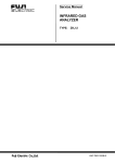
Fiberprime, Inc.
www.fiberprime.com
Tel: 1-613- 7214921
Email: [email protected]
Fax: 1-613-8289398
User Manual (draft)
L-band 20/21dBm EDFA Instrument in Benchtop
(EDFA-L-PG, version 1.0a. April 6, 2015)
Us er’s
1
Safety
Do not under any circumstances look at the output of the
optical port unless the equipment is turned off ! Containing a
high power invisible pump laser and amplified signal light, use the
utmost care when changing connections, and always turn the unit
completely off before inspecting or cleaning any connectors which
are attached to the unit’s output.
Laser Safety and Electrical Compliance
•
•
•
Maximum output power 500mW. Wavelength 960-1680nm. Max wavelength range: 15201620nm.
o Class IIIb laser product. Complies with 21 CFR 1040.10 and 1040.11 except for
deviations pursuant to Laser Notice No. 50, dated June 24, 2007.
o Class 3B laser product. Complies with IEC 60825-1, 60825-2 laser safety standards.
Complies with CE and other standards for electrical safety and EMI.
The internal AC-DC power supply module and optical EDFA module meet safety standards.
Introduction
L-band EDFA instrument in benchtop. Standard max output power: typical 20dBm version or
typical 21dBm version. Gain Flat. User can flexibly adjust EDFA output power, gain, and even
pump current from instrument front panel locally or from computer through RS-232 remotely. It
is designed for booster and line amplifier, it can also be used as pre-amplifier. Mid-stage-access
is available at much more cost.
EDFA-L-PG series optical fiber amplifier can operate at three control modes:
• Constant power: the EDFA maintains user-selected stage-specific output power.
• Constant gain: The EDFA maintains user-selected stage-specific gain.
• Constant current: The EDFA maintains user-selected laser diode-specific drive current of
pump lasers. Only available at remote mode at this moment. Local mode is available in much
longer lead time.
Front panel: Optical input and output ports with two fiber adapters (LC/PC interface by default,
other types are also available). 2x20 LCD. 5x4 numeric and arrow keypad. Keylock switch to
enable pump laser.
Rear panel: 100-120V/200-240V AC input with power switch. RS-232 adapter with switch for
remote control. Firmware adapter with switch for updating firmware.
Aluminum Enclosure dimension: 259(w) ×147(h) x 300(d) mm.
Operating temperature: from 0 to 40°C degree (higher temperature >50°C degree should be also
ok).
2
Key optical features:
•
•
•
•
Constant output power mode: Max 20dBm or 21dBm at large input signal (typically >
0dBm). Best for high input and may be ok for medium input power.
(Note: If set max output power 20dBm for 20dBm model or set 21dBm for 21dBm model,
input power should be over 0dBm typically, otherwise target output power may not be
reached, and pump laser drive current of EDFA may exceed max allowed value,
especially at longer wavelength. At front panel, max allowed set power is 22dBm for
21dBm-version EDFA; max set allowed power is 21dBm for 20dBm-version EDFA. No
such restriction if set power at remote mode.)
Constant gain mode: Best for medium input and is ok for small input power. Better
performance at <20dB gain setting at near 0dBm input, especially at shorter wavelength.
It also works at lower gain with high input power.
(Note: If gain is set too high, output power may exceed max 20dBm or 21dBm, then
target gain may not be reached, and pump laser drive current of EDFA may exceed max
allowed value, especially at longer wavelength. At front panel, max allowed set gain is
27dB. No such restriction if set gain at remote mode.)
Noise figure: 5dB typical. Normally <6dB. Noise figure is a little bit higher at shorter
wavelength.
Gain flatness: <1dB typically, at reasonable input power range (not too low input power).
Applications:
•
•
•
•
•
Instrumentation, Testing
Metro and Long-haul communications and optical switching systems.
LANS and MANs
Laboratory use
Cable television
Standard package includes:
•
•
•
•
Equipment enclosure including EDFA system and power supply module.
One power cable with AC plug type fitting your country.
Spectrum graphs of gain, noise figure, and output power tested at several input powers (29, -24, -19, -14, -9, -4, 1, 6dBm by default) over 1570-1603nm. One test data sheet of
these graphs.
User manual (draft)
Please tell us your preferred AC plug type. Our available AC power plug types are B, C, G, I.
Type B is mainly used in North and Centra America, Japan, Taiwan, and Thailand. Type C is mainly
used in Europe, South America & Asia. Type G is mainly used in UK, Ireland, Malaysia, Singapore,
& Hong Kong. Type I is mainly used in Australia, New Zealand, China & Argentina. See full list at
http://www.worldstandards.eu/electricity/plug-voltage-by-country/
3
Inspection
Before shipment, the unit has been found to be free of defects. The instrument part number and
serial number can be found on a label located at the back of the unit. The instrument history is
filed at the factory by part number and serial number.
Assembling Instrument after you receive the instrument
•
•
Connect your own two fiber patchcords to the adapters on front panel. (Please Do Not
screw FC connector into FC adapter too hard which may make connector dirty. To keep
internal fiber connectors clean and long lifetime, we recommend you try to keep fiber
jumpers connected on front panel adapters permanently).
Plug power cable into AC inlet on rear panel.
Getting Started
•
•
•
At the rear panel of equipment, turn on power switch above AC inlet.
On rear panel, “RS-232” switch should be at “Local” position, “Firmware” switch should
be at “Normal” position.
Insert key into key-lock switch on front panel, turn on the key-lock switch to enable EDFA.
Note: If there is reflection back to EDFA instrument, you cannot get max output power. For
example, for near 4% reflection from far end of fiber jumper FC/PC connector or from optical
receiver with air gap, you cannot get more than 16dBm output power. This arrangement is for
human safety. To reach max power, use APC connector at open end, or add isolator/attenuator.
Operation Instruction (Local mode)
•
•
•
•
•
•
•
After power on, the equipment is set at constant 10dBm output.
Press “MODE”, you can toggle between P (constant output power) mode and G (constant
gain) mode.
You can change output power or gain from keypad. For example, type in “19.51”, press
“ENTR” key, you will get 19.51dBm output in P mode, or 19.51dB gain in G mode.
Arrow keys: You can also adjust power or gain value by pressing arrow keys, changed
value will be executed after pressing “ENTER” key.
“ESC” key: Cancel all the digits you just typed (not pressed “ENTER” key yet), LCD
will show current power/gain value.
“-/BSC” key: Negative sign: If you have not typed any digit yet, LCD will show
negative sign “-“. Or backspace function: Cancel the last digit you just typed (not typed
“ENTER” key yet).
“OPTION” key: After press this key, LCD will show operating status for few seconds,
then go back to display of regular info.
4
•
•
If your keypad is locked probably due to typing error, turn “RS-232” switch to
“Remote(Reset)” position, then quickly turn back to “Local” position. The internal
microprocessor will reset to factory default condition, then keypad should be unlocked.
To avoid degrading pump laser, it is not recommended EDFA work at max output power
with low input power. When set power/gain is too high especially at low input power,
the pump laser current may exceed max allowed value, LCD will show “Alarm: Too high
current” at the 2nd line. To avoid degrade pump laser, please reduce output-power/gain or
increase input power accordingly. Sometimes, this alarm info cannot display on LCD in
time, you may press “OPTION” key to get up-to-date status.
Remote Control
For remote control, turn “RS-232” switch to “Remote” position. Keep “Firmware” switch at
“Normal” position. Link DB9-male to DB9-female cable between computer RS-232 serial port
and instrument “RS-232” port. Run HyperTerminal program on your computer. Operation
instruction is available by email upon request.
Update Firmware
If you need our updated software later, we can email you software, you download it to the
equipment internal flash memory. Turn “Firmware” switch to “Download” position, turn “RS232” switch at “Remote” position. Link DB9-male to DB9-female cable between computer RS232 serial port and instrument “Firmware” port. Operation instruction is available by email upon
request.
Cleaning optical connectors
After optical connectors plug in and pull out many times at front panel adapters, the connector
may not be easily cleaned, so we recommend that you keep external fiber jumpers connected on
front panel, and clean the fiber jumper connectors of far ends. You can unscrew the optical
adapter plate from right end of front panel, remove internal optical connectors, then use
traditional
method
to
clean
these
connectors,
see
http://www.lightwavestore.com/store/product.php?productid=20270&cat=369&page=1 .
Warranty: one year after delivery.
See details at http://www.lightwavestore.com/warranty%20and%20technical%20support.htm
Note: Never open the instrument enclosure, or warranty will be voided.
Ordering Information
P/N: EDFA-L-20-PG-1-LC: 20dBm output with LC/PC adapters (1: without mid-access stage).
P/N: EDFA-L-20-PG-1-FA: for 20dBm output with FC/APC adapters(without mid-access stage).
P/N: EDFA-L-21-PG-1-FP: for 21dBm output with FC/PC adapters(without mid-access stage).
5
Appendix 1: Amplifier Layout
Figure 1 shows the functional layout of the amplifier. Table 2 describes the labeled ports and
Monitor Photodiodes (MPDs).
Note: Basic L-band EDFA instrument is without MSA (Mid Stage Access)and only contains
one stage of gain.
Figure 1: Functional Block Diagram
Table 2: Amplifier Ports and MPDs
Name
Port A
Port B
Port M1
Port C
Port D
Port M2
MPD1
MPD2
MPD3
MPD4
Color
Blue
Green
Black
Orange
Red
Brown
-------------------------------------
Descriptio
Input to Amplifier, Input to Stage 1
Output to Mid-Stage Access (MSA), Output of Stage 1
Optical Monitor of Port B (approximately 20dB lower than Port B when VOA=0dB)
Input from MSA (See IOE Specifications for MSA loss), Input to Stage 2
Output of Amplifier, Output of Stage 2
Optical Monitor of Port D (approximately 18dB lower than Port D)
Monitor Photodiode of Port A
Monitor Photodiode of Port B, before VOA offset (MPD2 power equals Port B power plus VOA attenuation
Monitor Photodiode of Port C
Monitor Photodiode of Port D
6
Appendix 2: Specifications(draft)
Note: Following draft specifications are for max-21dBm amplifier with MSA (Mid-Stage
Access). For our standard EDFA amplifier without MSA, specifications should be similar.
Note: Optical power test is on internal fiber connectors. So gain result only includes one
connector loss.
L-BAND BOOSTER AMPLIFIER OPTICAL SPECIFICATION
at constant output power mode
SPECIFICATION
MINIMUM
TYPICAL
MAXIMUM
1570
–
1603
–
Total input power
-12
–
8
dBm
Total output power
–
21
–
dBm
Gain ripple (30° to 45° C)
–
–
1.0
dB
Gain ripple (0° to 70° C)
–
–
1.5
dB
Noise figure (at 5dBm total input power)
–
–
8
dB
Mid-stage loss
–
–
7(can be much higher) dB
Polarization Mode Dispersion (PMD)
–
–
0.4
ps
Polarization Dependent Gain (PDG)
–
–
0.3
dB
Transient suppression time
with 3dB power add/drop
–
50
100
µs
Maximum excursion with 3dB power add/drop
–
–
0.5
dB
Transient suppression time
with 6dB power add/drop
–
50
100
µs
Maximum excursion with 6dB power add/drop
–
0.5
1.0
dB
Bandwidth
Laser classification
UNITS
Class 3B under IEC/EN 60825-1
1100 Long-Haul/Ultr
7
L-BAND IN-LINE AMPLIFIER OPTICAL SPECIFICATION
at constant gain mode
SPECIFICATION
MINIMUM
TYPICAL
MAXIMUM
1570
–
1603
Bandwidth
Total input power
-22 (can be much lower as preamp)
UNITS
–
–
-2
Total output power
–
21
–
dBm
Gain ripple (30° to 45° C)
–
–
1.0
dB
Gain ripple (0° to 70° C)
–
–
1.5
dB
Noise figure (at -5dBm total input power)
–
–
6.5
dB
Mid-stage loss
–
–
10(can be much higher) dB
Polarization Mode Dispersion (PMD)
–
–
0.4
ps
Polarization Dependent Gain (PDG)
–
–
0.3
dB
Transient suppression time
with 3dB power add/drop
–
50
100
µs
Maximum excursion with 3dB power add/drop
–
–
0.5
dB
Transient suppression time
with 6dB power add/drop
–
50
100
µs
Maximum excursion with 6dB power add/drop
–
0.5
1.0
dB
Laser classification
Class 3B under IEC/EN 60825-1
Fiberprime, Inc.
Tel: 1-613-7214921
E-mail: [email protected], Fax: 1-613-8289398
Ottawa, Ontario, K2H 1A1, Canada
All information contained herein is believed to be accurate and is subject to change without notice. No responsibility is assumed for its use. F i b e r p r i m e , I n c . reserves the right to make
changes, without notice, to product design, product components, and product manufacturing methods. Some specific combinations of options may not be available. Please contact
Fiberprime, Inc. for more information.
© Fiberprime, Inc. All rights reserved.
Rev.1a 6/04/2015 Printed in Canada
8