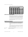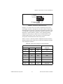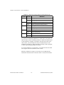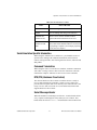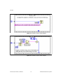
1
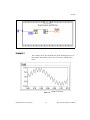
NI Instrument Simulator
User Manual
December 1997 Edition
Part Number 320638C-01
© Copyright 1996,1997 National Instruments Corporation. All Rights Reserved.
Internet Support
E-mail: [email protected]
FTP Site: ftp.natinst.com
Web Address: http://www.natinst.com
Bulletin Board Support
BBS United States: 512 794 5422
BBS United Kingdom: 01635 551422
BBS France: 01 48 65 15 59
Fax-on-Demand Support
512 418 1111
Telephone Support (USA)
Tel: 512 795 8248
Fax: 512 794 5678
International Offices
Australia 03 9879 5166, Austria 0662 45 79 90 0, Belgium 02 757 00 20, Brazil 011 288 3336,
Canada (Ontario) 905 785 0085, Canada (Québec) 514 694 8521, Denmark 45 76 26 00,
Finland 09 725 725 11, France 01 48 14 24 24, Germany 089 741 31 30, Hong Kong 2645 3186,
Israel 03 6120092, Italy 02 413091, Japan 03 5472 2970, Korea 02 596 7456, Mexico 5 520 2635,
Netherlands 0348 433466, Norway 32 84 84 00, Singapore 2265886, Spain 91 640 0085, Sweden 08 730 49 70,
Switzerland 056 200 51 51, Taiwan 02 377 1200, United Kingdom 01635 523545
National Instruments Corporate Headquarters
6504 Bridge Point Parkway Austin, Texas 78730-5039
USA Tel: 512 794 0100
Important Information
Warranty
The NI Instrument Simulator is warranted against defects in materials and workmanship for a period of two years from
the date of shipment, as evidenced by receipts or other documentation. National Instruments will, at its option, repair
or replace equipment that proves to be defective during the warranty period. This warranty includes parts and labor.
The media on which you receive National Instruments software are warranted not to fail to execute programming
instructions, due to defects in materials and workmanship, for a period of 90 days from date of shipment, as evidenced
by receipts or other documentation. National Instruments will, at its option, repair or replace software media that do
not execute programming instructions if National Instruments receives notice of such defects during the warranty
period. National Instruments does not warrant that the operation of the software shall be uninterrupted or error free.
A Return Material Authorization (RMA) number must be obtained from the factory and clearly marked on the outside
of the package before any equipment will be accepted for warranty work. National Instruments will pay the shipping
costs of returning to the owner parts which are covered by warranty.
National Instruments believes that the information in this manual is accurate. The document has been carefully
reviewed for technical accuracy. In the event that technical or typographical errors exist, National Instruments reserves
the right to make changes to subsequent editions of this document without prior notice to holders of this edition. The
reader should consult National Instruments if errors are suspected. In no event shall National Instruments be liable for
any damages arising out of or related to this document or the information contained in it.
EXCEPT AS SPECIFIED HEREIN , N ATIONAL INSTRUMENTS MAKES NO WARRANTIES, EXPRESS OR IMPLIED , AND
SPECIFICALLY DISCLAIMS ANY WARRANTY OF MERCHANTABILITY OR FITNESS FOR A PARTICULAR PURPOSE .
CUSTOMER’S RIGHT TO RECOVER DAMAGES CAUSED BY FAULT OR NEGLIGENCE ON THE PART OF NATIONAL
INSTRUMENTS SHALL BE LIMITED TO THE AMOUNT THERETOFORE PAID BY THE CUSTOMER. NATIONAL INSTRUMENTS
WILL NOT BE LIABLE FOR DAMAGES RESULTING FROM LOSS OF DATA , PROFITS , USE OF PRODUCTS , OR INCIDENTAL OR
CONSEQUENTIAL DAMAGES , EVEN IF ADVISED OF THE POSSIBILITY THEREOF . This limitation of the liability of National
Instruments will apply regardless of the form of action, whether in contract or tort, including negligence. Any action
against National Instruments must be brought within one year after the cause of action accrues. National Instruments
shall not be liable for any delay in performance due to causes beyond its reasonable control. The warranty provided
herein does not cover damages, defects, malfunctions, or service failures caused by owner’s failure to follow the
National Instruments installation, operation, or maintenance instructions; owner’s modification of the product;
owner’s abuse, misuse, or negligent acts; and power failure or surges, fire, flood, accident, actions of third parties,
or other events outside reasonable control.
Copyright
Under the copyright laws, this publication may not be reproduced or transmitted in any form, electronic or mechanical,
including photocopying, recording, storing in an information retrieval system, or translating, in whole or in part,
without the prior written consent of National Instruments Corporation.
Trademarks
CVI™, LabVIEW™, and The Software is the Instrument™ are trademarks of National Instruments Corporation.
Product and company names listed are trademarks or trade names of their respective companies.
WARNING REGARDING MEDICAL AND CLINICAL USE OF NATIONAL INSTRUMENTS PRODUCTS
National Instruments products are not designed with components and testing intended to ensure a level of reliability
suitable for use in treatment and diagnosis of humans. Applications of National Instruments products involving
medical or clinical treatment can create a potential for accidental injury caused by product failure, or by errors on the
part of the user or application designer. Any use or application of National Instruments products for or involving
medical or clinical treatment must be performed by properly trained and qualified medical personnel, and all traditional
medical safeguards, equipment, and procedures that are appropriate in the particular situation to prevent serious injury
or death should always continue to be used when National Instruments products are being used. National Instruments
products are NOT intended to be a substitute for any form of established process, procedure, or equipment used to
monitor or safeguard human health and safety in medical or clinical treatment.
FCC/DOC Radio Frequency Interference
Class A Compliance
This equipment generates and uses radio frequency energy and, if not installed and used in strict accordance
with the instructions in this manual, may cause interference to radio and television reception. Classification
requirements are the same for the Federal Communications Commission (FCC) and the Canadian
Department of Communications (DOC). This equipment has been tested and found to comply with the
following two regulatory agencies:
Federal Communications Commission
This equipment has been tested and found to comply with the limits for a Class A digital device, pursuant
to part 15 of the FCC Rules. These limits are designed to provide reasonable protection against harmful
interference when the equipment is operated in a commercial environment. This equipment generates,
uses, and can radiate radio frequency energy and, if not installed and used in accordance with the instruction
manual, may cause harmful interference to radio communications. Operation of this equipment in a
residential area is likely to cause harmful interference in which case the user will be required to correct the
interference at his own expense.
Notices to User:
Changes or modifications not expressly approved by National Instruments could void
the user’s authority to operate the equipment under the FCC Rules.
This device complies with the FCC rules only if used with shielded interface cables
of suitable quality and construction. National Instruments used such cables to test
this device and provides them for sale to the user. The use of inferior or nonshielded
interface cables could void the user’s authority to operate the equipment under the
FCC rules.
If necessary, consult National Instruments or an experienced radio/television technician for additional
suggestions. The following booklet prepared by the FCC may also be helpful: Interference to Home
Electronic Entertainment Equipment Handbook. This booklet is available from the U.S. Government
Printing Office, Washington, DC 20402.
Canadian Department of Communications
This Class A digital apparatus meets all requirements of the Canadian Interference-Causing Equipment
Regulations.
Cet appareil numérique de la classe A respecte toutes les exigences du Règlement sur le matériel brouilleur
du Canada.
Table of Contents
Chapter 1
Operation of the Simulator as a Serial or GPIB Device
NI Instrument Simulator Overview .............................................................................. 1-1
Rear Panel ..................................................................................................................... 1-1
GPIB Device Emulation ............................................................................................... 1-2
GPIB-Emulation Specific Information........................................................... 1-4
Serial Device Emulation ............................................................................................... 1-4
Serial-Emulation Specific Information........................................................... 1-7
Command Termination .................................................................... 1-7
RTS/CTS (Hardware Flow Control) ................................................ 1-7
Serial Message Header..................................................................... 1-7
End-of-String Character ................................................................... 1-8
ATN and SRQ LEDs........................................................................ 1-8
Common Problems With Serial Emulation .................................................... 1-8
Chapter 2
NI Instrument Simulator Command Set
Waveform Format......................................................................................................... 2-1
Simulator Commands ................................................................................................... 2-1
Address Command ......................................................................................... 2-2
Examples.......................................................................................... 2-2
Waveform Format Commands ....................................................................... 2-2
Examples.......................................................................................... 2-2
Waveform Generation Commands ................................................................. 2-3
Examples.......................................................................................... 2-3
Waveform Query Commands......................................................................... 2-3
Examples.......................................................................................... 2-4
Multimeter Configuration Commands ........................................................... 2-4
Examples.......................................................................................... 2-4
Other Commands............................................................................................ 2-5
© National Instruments Corporation
v
NI Instrument Simulator User Manual
Table of Contents
Chapter 3
Examples
LabVIEW Examples..................................................................................................... 3-1
Example 1 ...................................................................................................... 3-1
Example 2 ...................................................................................................... 3-4
Example 3 ...................................................................................................... 3-7
LabWindows/CVI Examples........................................................................................ 3-10
Example 1 ...................................................................................................... 3-10
Example 2 ...................................................................................................... 3-11
Example 3 ...................................................................................................... 3-12
IBIC Example............................................................................................................... 3-13
Documentation Comment Form
Figures
Figure 1-1.
Figure 1-2.
Figure 1-3.
Simulator Rear Panel............................................................................. 1-2
Sample GPIB Emulation Mode Switch Setting .................................... 1-2
Changing the S Mode Characteristics ................................................... 1-5
Figure 2-1.
Figure 2-2.
Three ESR Bits Set by the Simulator .................................................... 2-6
STB Byte and Description..................................................................... 2-7
Figure 3-1.
Figure 3-2.
Figure 3-3.
Figure 3-4.
Figure 3-5.
Figure 3-6.
Figure 3-7.
Figure 3-8.
Figure 3-9.
Figure 3-10.
Figure 3-11.
Figure 3-12.
Figure 3-13.
Figure 3-14.
Figure 3-15.
Example 1 Front Panel .......................................................................... 3-1
Example 1 Sequence Frame 0 Diagram ................................................ 3-2
Example 1 Sequence Frame 1 Diagram ................................................ 3-3
Example 2 Front Panel .......................................................................... 3-4
Example 2 Sequence Frame 0 Diagram ................................................ 3-4
Example 2 Sequence Frame 1 Diagram ................................................ 3-5
Example 2 Sequence Frame 2 Diagram ................................................ 3-5
Example 2 Sequence Frame 3 Diagram ................................................ 3-6
Example 2 Sequence Frame 4 Diagram ................................................ 3-6
Example 2 Sequence Frame 5 Diagram ................................................ 3-7
Example 3 Front Panel .......................................................................... 3-7
Example 3 Sequence Frame 0 Diagram ................................................ 3-8
Example 3 Sequence Frame 1 Diagram ................................................ 3-8
Example 3 Sequence Frame 2 Diagram ................................................ 3-9
Example 3 Sequence Frame 3 Diagram ................................................ 3-9
Tables
Table 1-1.
Table 1-2.
Table 1-3.
Table 1-4.
GPIB Address Switch Settings for GPIB Device Emulation ................ 1-3
S Mode Switch Settings for Serial Port Baud Rate ............................... 1-5
S Mode Switch Settings for Data Formatting Characteristics............... 1-6
LED Information in S Mode ................................................................. 1-7
NI Instrument Simulator User Manual
vi
© National Instruments Corporation
Chapter
1
Chapter 1
Operation
of the
Simulator
NI Instrument
Simulator
as
a SerialSet
or GPIB Device
Command
This chapter describes the different settings and information for using
the simulator as either a GPIB or serial device.
NI Instrument Simulator Overview
The NI Instrument Simulator allows the simulation of either a GPIB
device (G mode) or a serial device (S mode). In either mode, the
simulator emulates typical output from a digitizing oscilloscope or a
digital multimeter. In S mode, GPIB-specific functionality (SRQ and
GPIB addressing) are not supported.
The Instrument Simulator is ideal for debugging or training. Using the
simulator, instead of traditional instruments, to debug systems saves
time and effort. Also, National Instruments uses the simulator in our
customer education courses.
Rear Panel
The labeled configuration switches, located on the rear panel, control
the simulator emulation mode (G mode or S mode) as well as settings
specific to each mode. The unmarked DIP switches are reserved for
future development and should remain in the OFF position. Figure 1-1
shows the rear panel.
© National Instruments Corporation
1-1
NI Instrument Simulator User Manual
Operation of the Simulator as a Serial or GPIB Device
S MODE
DATA FORMAT
BAUD RATE
OFF
ON
ON
OFF
GPIB ADDRESS
G MODE
Figure 1-1. Simulator Rear Panel
GPIB Device Emulation
You can configure the simulator to mimic a GPIB device using the
switch settings on the rear panel of the unit. This emulation is similar to
an IEEE 488.2 device, but not to the exact specifications. To make the
simulator act as a GPIB device, set the S MODE/G MODE switch to
G MODE (switch 8 is ON as shown in Figure 1-2). Switches 6 and 7
must remain in the OFF position while the simulator is in G mode.
The primary GPIB address is determined using the switches labeled
“GPIB Address”. The secondary address can be set using the SADDR
command. If you want to change the primary address, power off the
unit and change the switch settings. Figure 1-2 shows the simulator
configured to emulate a GPIB device at primary GPIB address 2.
Note:
The numbers 1-8 do not actually appear on the box. They are included in
the picture as a reference aid.
S MODE
DATA FORMAT
BAUD RATE
OFF
12345678
ON
GPIB ADDRESS
G MODE
Figure 1-2. Sample GPIB Emulation Mode Switch Setting
NI Instrument Simulator User Manual
1-2
© National Instruments Corporation
Operation of the Simulator as a Serial or GPIB Device
The settings for each of the GPIB primary addresses are shown in
Table 1-1. The factory default setting, GPIB address 2, is shown in bold
italic.
Table 1-1. GPIB Address Switch Settings for GPIB Device Emulation
Switches
© National Instruments Corporation
GPIB
Address
1
2
3
4
5
OFF
OFF
OFF
OFF
OFF
0
ON
OFF
OFF
OFF
OFF
1
OFF
ON
OFF
OFF
OFF
2
ON
ON
OFF
OFF
OFF
3
OFF
OFF
ON
OFF
OFF
4
ON
OFF
ON
OFF
OFF
5
OFF
ON
ON
OFF
OFF
6
ON
ON
ON
OFF
OFF
7
OFF
OFF
OFF
ON
OFF
8
ON
OFF
OFF
ON
OFF
9
OFF
ON
OFF
ON
OFF
10
ON
ON
OFF
ON
OFF
11
OFF
OFF
ON
ON
OFF
12
ON
OFF
ON
ON
OFF
13
OFF
ON
ON
ON
OFF
14
ON
ON
ON
ON
OFF
15
OFF
OFF
OFF
OFF
ON
16
ON
OFF
OFF
OFF
ON
17
OFF
ON
OFF
OFF
ON
18
ON
ON
OFF
OFF
ON
19
OFF
OFF
ON
OFF
ON
20
ON
OFF
ON
OFF
ON
21
OFF
ON
ON
OFF
ON
22
ON
ON
ON
OFF
ON
23
OFF
OFF
OFF
ON
ON
24
1-3
NI Instrument Simulator User Manual
Operation of the Simulator as a Serial or GPIB Device
Table 1-1. GPIB Address Switch Settings for GPIB Device Emulation (Continued)
Switches
1
2
3
4
5
GPIB
Address
ON
OFF
OFF
ON
ON
25
OFF
ON
OFF
ON
ON
26
ON
ON
OFF
ON
ON
27
OFF
OFF
ON
ON
ON
28
ON
OFF
ON
ON
ON
29
OFF
ON
ON
ON
ON
30
ON
ON
ON
ON
ON
Undefined
GPIB-Emulation Specific Information
When the simulator is emulating a GPIB device, you must use a specific
command order in some cases. When you write a command that returns
data, you must perform a read of at least 1 byte before trying to send a
second command to the simulator. If you attempt to send a command
before reading some data, it is not accepted and the command times out.
If you perform a partial read of the simulator response to a command
request and then issue another command, the remaining data of the
partial read no longer exists.
Serial Device Emulation
You can configure the simulator to mimic a serial device using the
settings on the rear panel of the unit. If you want to change the
configuration of the simulator, power off the unit and change the switch
settings.
To make the simulator emulate a serial device, set the S mode/G mode
switch to S mode (switch 8 is OFF as shown in Figure 1-3). Switches 1
through 3 set the baud rate, and switches 4 through 7 set the data format.
Figure 1-3 shows the DIP switch.
Note:
The numbers 1-8 do not actually appear on the box. They are included in
the picture as a reference aid.
NI Instrument Simulator User Manual
1-4
© National Instruments Corporation
Operation of the Simulator as a Serial or GPIB Device
S MODE
DATA FORMAT
BAUD RATE
OFF
12345678
ON
GPIB ADDRESS
G MODE
Figure 1-3. Changing the S Mode Characteristics
In Figure 1-3, switch 8 is set to S mode, so the labels on top of the
switch apply. Switches 1 through 3 are ON, OFF, and ON, respectively,
indicating that the serial port is operating at 9600 baud. Switches 4 and
5 are both OFF, which indicates that parity is disabled. Switch 6 is OFF,
indicating 1 stop bit/character. Switch 7 is ON, indicating that the
simulator is using 8 bits per character for serial data transfers. The
unmarked DIP switches on the rear panel are reserved for future
development and should remain in the OFF position.
Tables 1-2 and 1-3 show the possible configurations for the baud rate
and data format switches when you are using serial emulation and what
each configuation indicates.
Table 1-2. S Mode Switch Settings for Serial Port Baud Rate
Switches
© National Instruments Corporation
1
2
3
Baud Rate
OFF
OFF
OFF
300
ON
OFF
OFF
600
OFF
ON
OFF
1200
ON
ON
OFF
2400
OFF
OFF
ON
4800
ON
OFF
ON
9600
OFF
ON
ON
Reserved
ON
ON
ON
Reserved
1-5
NI Instrument Simulator User Manual
Operation of the Simulator as a Serial or GPIB Device
Table 1-3. S Mode Switch Settings for Data Formatting Characteristics
Switch
4
5
6
7
8
Position
Indication
OFF
Odd parity
ON
Even parity
OFF
Parity generation/checking disabled
ON
Parity generation/checking enabled
OFF
1 stop bit/character
ON
2 stop bits per character
OFF
7 bits per character
ON
8 bits per character
OFF
Operation in S mode
ON
Operates in G mode
To operate the Instrument Simulator as a serial device, set switch 8 to
OFF (S mode). Set the remaining switches to match the characteristics
of the terminal or computer you attach to the other end of the serial
cable. Often, you can change the serial port characteristics of the
terminal or computer by setting switches or running a utility program,
or from within a programming environment.
To use the simulator as a serial device, your software and serial cable
must support RTS/CTS (Hardware) flow control.
When the simulator is acting as a serial device, the LEDs provide
information about the state of the unit. Table 1-4 describes each state.
NI Instrument Simulator User Manual
1-6
© National Instruments Corporation
Operation of the Simulator as a Serial or GPIB Device
.
Table 1-4. LED Information in S Mode
LED
State of the Unit
LISTEN
Unit is waiting for a command.
TALK
Unit is sending data using serial interface.
LISTEN and
TALK are ON
Receive error-current command will be
ignored. Resend command to clear error.
LISTEN and
TALK are both
OFF
When the unit has the ready and power LEDs
ON, but the listen and talk LEDs are off, the unit
is preparing a response (for example, preparing
a sine wave for output.)
Serial-Emulation Specific Information
When using the simulator as a serial device, you should be aware of
special issues dealing with command termination, RTS/CTS flow
control, message headers, end-of-string character choice, and ATN and
SRQ LEDs.
Command Termination
When using the unit as a serial device simulator, terminate commands
with either a carriage return or line feed so the unit knows when the
command is complete, otherwise it does not act on the command.
RTS/CTS (Hardware Flow Control)
The unit uses RTS/CTS flow control to indicate when it is ready to
receive data and when the controller is ready to receive data. This
prevents data corruption and errors that may occur when the unit is not
ready to receive data. You must use a serial cable and software that
supports RTS/CTS flow control.
Serial Message Header
When the simulator is emulating a serial device, it sends a header before
every response indicating how many data bytes are to follow. This
header takes the form of xxxxx\r\n and should be read to indicate how
© National Instruments Corporation
1-7
NI Instrument Simulator User Manual
Operation of the Simulator as a Serial or GPIB Device
many bytes will follow. An example is a response to the "*tst?"
command.
Command: *tst?
Response: 00003\r\nOK\n
The 00003 indicates that there are three more bytes after the header.
The header eliminates timeouts due to reading the serial port before data
is present and specifies how much data is actually present. This
information is important because serial transfers do not specify an
end-of-string character.
End-of-String Character
For serial input from the simulator, the EOS character should be set to
NONE because simulator responses can contain the NULL byte (00)
and \r\n, which could cause a premature termination of the serial port
read.
ATN and SRQ LEDs
The ATN and SRQ LEDs indicate service request and attention
assertion and are useful only for GPIB emulation. The ATN LED may
be lit, but you should ignore it if the simulator is in serial emulation
mode. The SRQ LED indicates that the device is requesting service,
but use it as a visual clue only. You should read the STB register to
determine the status byte.
Common Problems With Serial Emulation
Other serial mode considerations are as follows:
•
If you are sending commands but the serial simulator is not
responding, be sure that the commands are terminated with a
carriage return or line feed.
•
If you notice that you are not receiving the complete message, for
example "sys:help?" only sends back "SYS:HELP?", check the
EOS character being used. It should be set to NONE. If it is set to
LF or CR, the read is terminated prematurely.
NI Instrument Simulator User Manual
1-8
© National Instruments Corporation
Chapter
2 Chapter 2
NI Instrument
Instrument Simulator
Simulator
NI
Command Set
Set
Command
This chapter describes the command set used by the Instrument
Simulator, including examples to illustrate usage.
Waveform Format
The Instrument Simulator generates a 128-point waveform in either
ASCII or binary. ASCII waveforms are preceded by the header CURVE.
Binary waveforms are preceded by a pound sign (#) and the number of
bytes that are in the waveform. All waveforms terminate with a line feed
<LF> character.
Floating Point ASCII (default)
CURVE<space>num0,num1,...,num127<LF>
The floating point format used is [+][-]1.2345[E[+][-]0]
8-bit Unsigned Binary
#3128<Byte 0><Byte 1>...<Byte127><LF>
16-bit Signed Binary (NORMal byte order)
#3256<MSB 0><LSB 0>...<MSB 127><LSB 127><LF>
16-bit Signed Binary (SWAPped byte order)
#3256<LSB 0><MSB 0>...<LSB 127><MSB 127><LF>
Simulator Commands
The Instrument Simulator uses SCPI-like commands. The commands
are shown in long form; however, the simulator accepts only the short
form of the command. Send only the part of the command that is shown
in BOLD UPPERCASE characters. You can send multiple commands
to the simulator by separating them with a semicolon (;).
© National Instruments Corporation
2-1
NI Instrument Simulator User Manual
NI Instrument Simulator Command Set
Address Command
You can use the address command to change the GPIB address used by
the simulator. The power-on default for the primary GPIB address is
determined by the rear panel switch setting. Secondary addressing is
disabled by default. The address command is used as follows:
SADDRess primary, secondary
Examples
SADDR 2
Set the address to 2
SADDR 3, 4
Set the primary address to 3 and the
secondary address to 4
Waveform Format Commands
The following commands format how the waveform data is returned by
the simulator.
FORMat:DATA
Floating point (default)
8-bit unsigned binary
16-bit signed binary
ASCii
INTeger,8
INTeger,16
Returns the current waveform format
FORMat:DATA?
The following command changes the order of the bytes returned by
INTeger,16 encoding.
FORMat:BORDer
High byte first <MSB><LSB>
Low byte first<LSB><MSB>
(default)
NORMal
SWAPped
Returns the current format of the byte
order
FORMat:BORDer?
Examples
FORM:DATA INT,16
NI Instrument Simulator User Manual
2-2
Set the waveform format as
16-bit integers
© National Instruments Corporation
NI Instrument Simulator Command Set
Query the current waveform format.
For example, if the command was
issued after the preceding command,
it would return
FORM:DATA INT,16<LF>
FORM:DATA?
Waveform Generation Commands
These commands generate a 128-point waveform of the specified type.
The number of cycles in the waveform is random. Waveform generation
can take 2 to 15 seconds, depending on the format and type of the
waveform. Typically, ASCII waveforms take longer than binary
waveforms.
SOURce:FUNCtion
SINusoid
SQUare
NOISe
RANDom
PCHirp
Sine waveform (default)
Square waveform
Noisy sine waveform
Random noise waveform
Chirp waveform
SOURce:FUNCtion?
Returns the current waveform type
Examples
SOUR:FUNC SIN
Generate a sinusoid waveform
SOUR:FUNC?
Query the current waveform type. For
example, if the command was issued
after the preceding command, it would
return SOUR:FUNC SIN<LF>
Waveform Query Commands
Returns the waveform data in the
format specified by the waveform
format commands
SENSe:DATA?
SENSe:VOLTage:RANGe:OFFSet?
Returns the Y offset for
the waveform in ASCII
floating point
SENSe:VOLTage:RANGe? Returns the Y multiplier for the
waveform in ASCII floating point
© National Instruments Corporation
2-3
NI Instrument Simulator User Manual
NI Instrument Simulator Command Set
SENSe:SWEep:TIME?
Returns the X increment (1E-3) in
ASCII floating point
SENSe:VOLTage:HEADer? Returns all of the waveform scaling
information in the format
OFFSET=x.xxxxE+x,
RANGE=x.xxxxE+x,
TIME=1E-3<LF>
For integer-formatted waveforms, the offset and range are used to scale
the raw integer data as follows:
ScaledPoint[i] = (WaveformPoint[i] + offset) * range
Examples
SENS:DATA?
Query simulator for the waveform
SENS:VOLT:HEAD?
Query simulator for the waveform
scaling information
Multimeter Configuration Commands
These commands simulate the operation of a meter. They return one
value in ASCII floating point.
Returns a random value between 0 to +x
in floating point ASCII. The range of x
depends on the CONFigure:DC
command
MEASure:DC?
CONFigure:DC
DEFault
MEASure:DC? returns a number
between 0 and 10
MEASure:DC? returns a number
between 0 and 1
MEASure:DC? returns a number
between 0 and 100
MIN
MAX
Returns the current configuration
setting
CONFigure:DC?
Examples
Set the maximum range
CONF:DC MAX
NI Instrument Simulator User Manual
2-4
© National Instruments Corporation
NI Instrument Simulator Command Set
CONF:DC?
Query the current DC range. For
example, if the command was issued
after the command above, it would
return CONF:DC MAX<LF>
MEAS:DC?
Queries one value, for example
1.2308<LF>
Other Commands
These commands perform miscellaneous functionality as indicated in
the description of each command.
*IDN?
Returns National Instruments
GPIB and Serial Device
Simulator Rev B.x <LF>
*RST
Resets the simulator to its default state
*TRG
Triggers the simulator and returns one
random reading (same as MEAS:DC?)
*TST?
Simulates testing the simulator, returns
OK
*OPC
Sets the operation complete bit in the
Standard Event Status Register (ESR)
*OPC?
Returns a 1 regardless of the OPC bit
value.
FORMat:SREGister
ASCii
HEX
Specifies the output of ESR,
ESE, STB, and SRE registers as an
ASCII string (default)
Specifies the output of ESR, ESE,
STB, and SRE registers in hex
Returns value of Standard Event Status
register as specified by FORM:SREG
*ESR?
Figure 2-1 illustrates the bits defined by the simulator for the ESR
register: bit 7 (Power On), bit 5 (Command Error), and bit 0 (Operation
Complete). Bit 7 is set when the simulator is powered on; bit 5 is set
when the simulator receives an invalid command; bit 0 is set when the
simulator receives the *OPC command. You can use the *ESR?
© National Instruments Corporation
2-5
NI Instrument Simulator User Manual
NI Instrument Simulator Command Set
Command Error
Power On
7
Operation Complete
command to query the value of the ESR register. The value returned is
in either ASCII or HEX, as specified by the FORMat:SREGister
command. The ESR register is cleared after you read it.
6
5
4
3
2
1
0
Figure 2-1. Three ESR Bits Set by the Simulator
*ESE 0x##
Sets value of Standard Event Status
Enable register, ## represents a mask
in hex
*ESE?
Returns value of Standard Event Status
Enable register as specified by
FORM:SREG
*STB?
Returns value of Status Byte register
as specified by FORM:SREG
Figure 2-2 illustrates the bits defined by the simulator for the STB
register: bit 6 (Request Service), bit 5 (ESB condition is met) and bit 4
(Message Available “MAV” is true). When any of these conditions are
set in the SRE byte, and it becomes set in the STB, an SRQ is generated.
The SRQ bit is cleared after the request is serviced. You can use the
Serial Poll Service (G mode only), or request the STB using the *STB?
command to query the status information. The value returned is either
ASCII or HEX, depending on the format specified by the
FORMat:SREGister command.
NI Instrument Simulator User Manual
2-6
© National Instruments Corporation
ESE & ESR
MAV
7
SRQ
NI Instrument Simulator Command Set
6
5
4
3
2
1
0
Figure 2-2. STB Byte and Description
*SRE 0x##
Sets value of Service Request Enable
register. ## represents a mask in hex.
*SRE?
Returns value of Service Request
Enable register as specified by
FORM:SREG
*WAI
No functionality; included to make the
simulator IEEE 488.2 compatible
FORMat:SREGister?
Returns the current format of the
registers
SYStem:HELP?
Returns a list of all of the commands
© National Instruments Corporation
2-7
NI Instrument Simulator User Manual
Chapter
3
Chapter
3
NI Instrument
Simulator
Examples
Command Set
This chapter gives several sample Instrument Simulator applications.
The examples use LabVIEW, LabWindows/CVI, and IBIC (the GPIB
interactive control utility).
LabVIEW Examples
Example 1
This example shows the front panel and diagrams for a VI that acquires
and displays a square wave from a LabVIEW simulator in G mode or
S mode.
Figure 3-1. Example 1 Front Panel
© National Instruments Corporation
3-1
NI Instrument Simulator User Manual
Examples
Figure 3-2. Example 1 Sequence Frame 0 Diagram
NI Instrument Simulator User Manual
3-2
© National Instruments Corporation
Examples
Figure 3-3. Example 1 Sequence Frame 1 Diagram
© National Instruments Corporation
3-3
NI Instrument Simulator User Manual
Examples
Example 2
This example shows the LabVIEW front panel and diagrams for a
VI that configures the simulator in G mode to assert an SRQ after
generating a chirp wave. The generated chirp wave is retrieved and
displayed.
Figure 3-4. Example 2 Front Panel
Figure 3-5. Example 2 Sequence Frame 0 Diagram
NI Instrument Simulator User Manual
3-4
© National Instruments Corporation
Examples
Figure 3-6. Example 2 Sequence Frame 1 Diagram
Figure 3-7. Example 2 Sequence Frame 2 Diagram
© National Instruments Corporation
3-5
NI Instrument Simulator User Manual
Examples
Figure 3-8. Example 2 Sequence Frame 3 Diagram
Figure 3-9. Example 2 Sequence Frame 4 Diagram
NI Instrument Simulator User Manual
3-6
© National Instruments Corporation
Examples
Figure 3-10. Example 2 Sequence Frame 5 Diagram
Example 3
This example shows the LabVIEW front panel and diagrams for a VI
that acquires and displays a noisy sine wave from a simulator in G
mode.
Figure 3-11. Example 3 Front Panel
© National Instruments Corporation
3-7
NI Instrument Simulator User Manual
Examples
Figure 3-12. Example 3 Sequence Frame 0 Diagram
Figure 3-13. Example 3 Sequence Frame 1 Diagram
NI Instrument Simulator User Manual
3-8
© National Instruments Corporation
Examples
Figure 3-14. Example 3 Sequence Frame 2 Diagram
Figure 3-15. Example 3 Sequence Frame 3 Diagram
© National Instruments Corporation
3-9
NI Instrument Simulator User Manual
Examples
LabWindows/CVI Examples
Example 1
/*This example shows how to use a GPIB device to request a square wave and then read
the data and plot the response*/
#include <formatio.h>
#include <userint.h>
#include <gpib.h>
char buffer[2000];
double waveform[2000];
int ud0, ud1;
int main (int argc, char *argv[])
{
/*initializes the gpib board*/
ud0 = ibfind ("gpib0");
/*sets the board as controller in charge*/
ibsic (ud0);
/*opens and initializes the device*/
ud1 = ibfind ("DEV2");
/*writes the command string*/
ibwrt (ud1, "SOUR;FUNC SQU;SENS:DATA?", 24);
/*reads the response data from the device*/
ibrd (ud1, buffer, 2000);
/*discards the header and converts ASCII data to floating point array*/
Scan (buffer, "%s[i6]>5250f[x]", waveform);
/*plots the data*/
YGraphPopup ("Waveform Plot", waveform, 130, VAL_DOUBLE);
return 0;
}
NI Instrument Simulator User Manual
3-10
© National Instruments Corporation
Examples
Example 2
/*This example shows how to use the device as a serial device and request a square
wave and then plot it*/
#include
#include
#include
#include
<rs232.h>
<formatio.h>
<userint.h>
<gpib.h>
int main (int argc, char *argv[])
{
char buffer[2000];
char header[8];
double waveform[2000];
int ComPort = 1;
int ByteCount;
/*opens the COM port and configures it for the serial settings*/
OpenComConfig (ComPort, "com1", 9600, 0, 8, 1, 512, 512);
/*writes the command string to the port, note the linefeed at the end*/
ComWrt (ComPort, "SOUR:FUNC SQU;SENS:DATA?\n", 25);
/*reads the header to determine how many bytes will follow*/
ComRd (ComPort, header, 7);
/*converts the ASCII header into an integer byte count*/
Scan (header, "%s>%i", &ByteCount);
/*reads the actual data from the device*/
ComRd (ComPort, buffer, ByteCount);
/*closes the COM port so other applications can use it*/
CloseCom (ComPort);
/*discards the header and converts ASCII data to floating point array*/
Scan (buffer, "%s[i6]>%250f[x]", waveform);
/*plots the data*/
YGraphPopup ("Waveform Plot", waveform, 128, VAL_DOUBLE);
return 0;
}
© National Instruments Corporation
3-11
NI Instrument Simulator User Manual
Examples
Example 3
/*This example shows how to setup the simulator to assert an SRQ after it generates
a chirp wave and is ready to output the data*/
#include <gbib.h>
#include <formatio.h>
#include <userint.h>
int main (int argc, char *argv[])
{
char buffer[2000]
double waveform[2000];
int ud0, ud1;
static char SPR;
/*initializes the gpib board*/
ud0 = ibfind ("gpib0");
/*sets the board as controller in charge*/
ibsic (ud0);
/*opens and initializes the device*/
ud1 = ibfind ("DEV2");
/*changes the software configuration parameters*/
ibconfig (ud0, IbcAUTOPOLL, 0);
/*writes data to the device*/
ibwrt (ud1, "*SRE 0x10;SOUR:FUNC PCH;SENS:DATA?", 34);
/*waits for the SRQ line to be asserted indicating message available*/
ibwait (ud0, SRQI);
/*conducts a serial poll*/
ibrsp (ud1, &SPR);
/*reads the response data from the device*/
ibrd (ud1, buffer, 2000);
/*discards the header and converts to floating point*/
Scan (buffer, "%s[i6]>%128f[x]", waveform);
/*plots the returned waveform*/
YGraphPopup ("Waveform Plot", waveform, 128, VAL_DOUBLE);
return 0;
}
NI Instrument Simulator User Manual
3-12
© National Instruments Corporation
Examples
IBIC Example
The following example uses the National Instruments text-based
interactive control program (IBIC for GPIB) to communicate with a
simulator in G mode. Several of the miscellaneous commands are
demonstrated. Bold text indicates that the text is automatically printed
to the screen.
When you launch IBIC, text similar to the following appears on the
screen.
National Instruments
wIN32 Interactive Control Program
Copyright (C) 1996 National Instruments,Corp.
All rights reserved.
Type 'help' for help or 'q' to quit.
Use ibdev to open a device descriptor connected to GPIB0, referencing
the device with primary address (PAD) 2 and no secondary address
(SAD). The device descriptor uses a 10 s I/O timeout, asserts EOI on
the last byte of writes, and uses no EOS modes.
: ibdev 0 2 0 13 1 0
Use ibwrt to request simulator identification as follows.
ud0: ibwrt "*idn?"
[0100]
( cmpl )
count: 5
Use ibrd to read the simulator identification, which is returned as
follows.
ud0: ibrd 1000
[2100]
count:
4e 61
20 49
65 6e
42 20
72 69
69 63
6c 61
76 20
© National Instruments Corporation
( end cmpl )
62
74 69 6f 6e
6e 73 74 72
74 73 20 47
61 6e 64 20
61 6c 20 44
65 20 53 69
74 6f 72 20
42 2e 31 0a
3-13
61
75
50
53
65
6d
52
6c
6d
49
65
76
75
65
N a
I
e n
B
r i
i c
l a
v
t
n
t
a
a
e
t
B
i o n a l
s t r u m
s
G P I
n d
S e
l
D e v
S i m u
o r
R e
. 1 .
NI Instrument Simulator User Manual
Examples
Use ibwrt to request a simulator test as follows.
ud0: ibwrt "*tst?"
[0100]
( cmpl )
count: 5
Read the simulator test response.
ud0: ibrd 1000
[2100]
( end cmpl )
count: 3
6f 6b 0a
o k.
Query the current DC range, then read the DC range, as follows.
ud0: ibwrt "conf:dc?"
[0100]
( cmpl )
count: 8
ud0: ibrd 1000
[2100]
( end cmpl )
count: 13
43 4f 4e 46 3a 20
20 44 45 46 0a
44
43
C O N F :
D E F .
D C
Set the maximum response range, then query and read the current DC
range again, as follows.
ud0: ibwrt "conf:dc max"
[0100]
( cmpl )
count: 11
ud0: ibwrt "conf:dc?"
[0100]
( cmpl )
count: 8
ud0: ibrd 1000
[2100]
( end cmpl )
count: 13
43 4f 4e 46 3a 20 44
20 4d 41 58 0a
43
C O N F :
M A X .
D C
Request a DC measurement.
ud0: ibwrt "meas:dc?"
[0100]
( cmpl )
count: 8
NI Instrument Simulator User Manual
3-14
© National Instruments Corporation
Examples
Request the DC measurement.
ud0: ibrd 1000
[2100]
( end cmpl )
count: 9
30 2e 37 39 32 35
0a
45
32
0 . 7 9 2 5 E 2
.
Set the GPIB address of the simulator to PAD 7, SAD 99.
ud0: ibwrt "saddr 7,99"
[0100]
( cmpl )
count: 10
Change the IBIC descriptor to reference device at PAD 7 and SAD 99.
ud0: ibpad 7
[0100]
( cmpl
previous value:
ud0: ibsad 99
[0100]
( cmpl
previous value:
)
2
)
0
Trigger and then read a DC measurement.
ud0: ibwrt "*trg?"
[0100]
( cmpl )
count: 5
ud0: ibrd 1000
[2100]
( end cmpl )
count: 9
36 2e 30 35 30 39
0a
45
31
6 . 0 5 0 9 E 1
.
Reset the simulator to the default settings.
ud0: ibwrt "*rst"
[0100]
( cmpl )
count: 4
Reset the IBIC descriptor to the default settings.
ud0: ibonl 1
[0100]
( cmpl )
© National Instruments Corporation
3-15
NI Instrument Simulator User Manual
Examples
Query for waveform scaling information, then read the result.
ud0: ibwrt "sens:volt:head?"
[0100]
( cmpl )
count: 15
ud0: ibrd 1000
[2100]
( end cmpl )
count: 33
4f 46 46 53 45 54 3d 30
2e 30 2c 52 41 4e 47 45
3d 31 2e 30 2c 54 49 4d
45 3d 31 2e 30 45 2d 33
0a
O
.
=
E
.
F
0
1
=
F
,
.
1
S
R
0
.
E
A
,
0
T
N
T
E
=
G
I
-
0
E
M
3
Place the IBIC descriptor offline.
ud0: ibonl 0
[0100]
( cmpl )
NI Instrument Simulator User Manual
3-16
© National Instruments Corporation
Documentation Comment Form
National Instruments encourages you to comment on the documentation supplied with our products.
This information helps us provide quality products to meet your needs.
Title:
NI Instrument Simulator User Manual
Edition Date:
December 1997
Part Number:
320638C-01
Please comment on the completeness, clarity, and organization of the manual.
_______________________________________________________________________________
_______________________________________________________________________________
_______________________________________________________________________________
_______________________________________________________________________________
_______________________________________________________________________________
_______________________________________________________________________________
_______________________________________________________________________________
If you find errors in the manual, please record the page numbers and describe the errors.
_______________________________________________________________________________
_______________________________________________________________________________
_______________________________________________________________________________
_______________________________________________________________________________
_______________________________________________________________________________
_______________________________________________________________________________
_______________________________________________________________________________
Thank you for your help.
Name _________________________________________________________________________
Title __________________________________________________________________________
Company _______________________________________________________________________
Address ________________________________________________________________________
_______________________________________________________________________________
Phone ( ___ )__________________________ Fax ( ___ ) ________________________________
Mail to: Customer Education
National Instruments Corporation
6504 Bridge Point Parkway
Austin, TX 78730-5039
Fax to:
Customer Education
National Instruments Corporation
(512) 794-5678