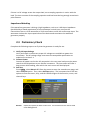
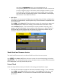
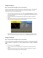
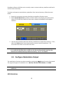
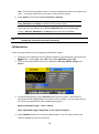
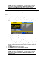
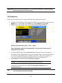
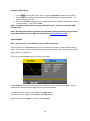
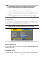
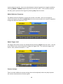
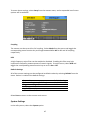
Download 4060 Series Arbitrary Function Generator User Manual

Transcript
Model: 4063, 4064, 4065
Function/Arbitrary Waveform
Generator
USER MANUAL
Safety Summary
The following safety precautions apply to both operating and maintenance personnel and
must be followed during all phases of operation, service, and repair of this instrument.
Before applying power to this instrument:
 Read and understand the safety and operational information in this manual.
 Apply all the listed safety precautions.
 Verify that the voltage selector at the line power cord input is set to the correct line
voltage. Operating the instrument at an incorrect line voltage will void the warranty.
 Make all connections to the instrument before applying power.
 Do not operate the instrument in ways not specified by this manual or by B&K
Precision.
Failure to comply with these precautions or with warnings elsewhere in this manual violates
the safety standards of design, manufacture, and intended use of the instrument. B&K
Precision assumes no liability for a customer’s failure to comply with these requirements.
Category rating
The IEC 61010 standard defines safety category ratings that specify the amount of electrical
energy available and the voltage impulses that may occur on electrical conductors
associated with these category ratings. The category rating is a Roman numeral of I, II, III, or
IV. This rating is also accompanied by a maximum voltage of the circuit to be tested, which
defines the voltage impulses expected and required insulation clearances. These categories
are:
Category I (CAT I): Measurement instruments whose measurement inputs are not intended
to be connected to the mains supply. The voltages in the environment are typically derived
from a limited-energy transformer or a battery.
Category II (CAT II): Measurement instruments whose measurement inputs are meant to be
connected to the mains supply at a standard wall outlet or similar sources. Example
measurement environments are portable tools and household appliances.
Category III (CAT III): Measurement instruments whose measurement inputs are meant to be
connected to the mains installation of a building. Examples are measurements inside a
building's circuit breaker panel or the wiring of permanently-installed motors.
Category IV (CAT IV): Measurement instruments whose measurement inputs are meant to
be connected to the primary power entering a building or other outdoor wiring.
i
Do not use this instrument in an electrical environment with a higher category rating than
what is specified in this manual for this instrument.
You must ensure that each accessory you use with this instrument has a category rating
equal to or higher than the instrument's category rating to maintain the instrument's
category rating. Failure to do so will lower the category rating of the measuring system.
Electrical Power
This instrument is intended to be powered from a CATEGORY II mains power environment.
The mains power should be 120 V RMS or 240 V RMS. Use only the power cord supplied
with the instrument and ensure it is appropriate for your country of use.
Ground the Instrument
To minimize shock hazard, the instrument chassis and cabinet must be connected to an
electrical safety ground. This instrument is grounded through the ground conductor of the
supplied, three-conductor AC line power cable. The power cable must be plugged into an
approved three-conductor electrical outlet. The power jack and mating plug of the power
cable meet IEC safety standards.
Do not alter or defeat the ground connection. Without the safety ground connection, all
accessible conductive parts (including control knobs) may provide an electric shock. Failure
to use a properly-grounded approved outlet and the recommended three-conductor AC line
power cable may result in injury or death.
Unless otherwise stated, a ground connection on the instrument's front or rear panel is for a
reference of potential only and is not to be used as a safety ground.
Do not operate in an explosive or flammable atmosphere
Do not operate the instrument in the presence of flammable gases or vapors, fumes, or
finely-divided particulates.
ii
The instrument is designed to be used in office-type indoor environments. Do not operate
the instrument







In the presence of noxious, corrosive, or flammable fumes, gases, vapors, chemicals,
or finely-divided particulates.
In relative humidity conditions outside the instrument's specifications.
In environments where there is a danger of any liquid being spilled on the
instrument or where any liquid can condense on the instrument.
In air temperatures exceeding the specified operating temperatures.
In atmospheric pressures outside the specified altitude limits or where the
surrounding gas is not air.
In environments with restricted cooling air flow, even if the air temperatures are
within specifications.
In direct sunlight.
This instrument is intended to be used in an indoor pollution degree 2 environment. The
operating temperature range is 0 °C to 40 °C and the operating humidity is ≤ 90 % relative
humidity at < 35 °C and ≤ 60 % relative humidity at 35 °C – 40 °C, with no condensation
allowed.
Measurements made by this instrument may be outside specifications if the instrument is
used in non-office-type environments. Such environments may include rapid temperature or
humidity changes, sunlight, vibration and/or mechanical shocks, acoustic noise, electrical
noise, strong electric fields, or strong magnetic fields.
Do not operate instrument if damaged
If the instrument is damaged, appears to be damaged, or if any liquid, chemical, or other
material gets on or inside the instrument, remove the instrument's power cord, remove the
instrument from service, label it as not to be operated, and return the instrument to B&K
Precision for repair. Notify B&K Precision of the nature of any contamination of the
instrument.
Clean the instrument only as instructed
iii
Do not clean the instrument, its switches, or its terminals with contact cleaners, abrasives,
lubricants, solvents, acids/bases, or other such chemicals. Clean the instrument only with a
clean dry lint-free cloth or as instructed in this manual.
Not for critical applications
This instrument is not authorized for use in contact with the human body or for use as a
component in a life-support device or system.
Do not touch live circuits
Instrument covers must not be removed by operating personnel. Component replacement
and internal adjustments must be made by qualified service-trained maintenance personnel
who are aware of the hazards involved when the instrument's covers and shields are
removed. Under certain conditions, even with the power cord removed, dangerous voltages
may exist when the covers are removed. To avoid injuries, always disconnect the power cord
from the instrument, disconnect all other connections (for example, test leads, computer
interface cables, etc.), discharge all circuits, and verify there are no hazardous voltages
present on any conductors by measurements with a properly-operating voltage-sensing
device before touching any internal parts. Verify the voltage-sensing device is working
properly before and after making the measurements by testing with known-operating
voltage sources and test for both DC and AC voltages. Do not attempt any service or
adjustment unless another person capable of rendering first aid and resuscitation is present.
Do not insert any object into an instrument's ventilation openings or other openings.
Hazardous voltages may be present in unexpected locations in circuitry being tested when a
fault condition in the circuit exists.
Servicing
Do not substitute parts that are not approved by B&K Precision or modify this instrument.
Return the instrument to B&K Precision for service and repair to ensure that safety and
performance features are maintained.
Cooling fans
iv
This instrument contains one or more cooling fans. For continued safe operation of the
instrument, the air inlet and exhaust openings for these fans must not be blocked nor must
accumulated dust or other debris be allowed to reduce air flow. Maintain at least 25 mm
clearance around the sides of the instrument that contain air inlet and exhaust ports. If
mounted in a rack, position power devices in the rack above the instrument to minimize
instrument heating while rack mounted. Do not continue to operate the instrument if you
cannot verify the fan is operating (note some fans may have intermittent duty cycles). Do
not insert any object into the fan's inlet or outlet.
For continued safe use of the instrument





Do not place heavy objects on the instrument.
Do not obstruct cooling air flow to the instrument.
Do not place a hot soldering iron on the instrument.
Do not pull the instrument with the power cord, connected probe, or connected test
lead.
Do not move the instrument when a probe is connected to a circuit being tested.
v
Compliance Statements
Disposal of Old Electrical & Electronic Equipment (Applicable in the European
Union and other European countries with separate collection systems)
This product is subject to Directive 2002/96/EC of the European
Parliament and the Council of the European Union on waste
electrical and electronic equipment (WEEE), and in jurisdictions
adopting that Directive, is marked as being put on the market after
August 13, 2005, and should not be disposed of as unsorted
municipal waste. Please utilize your local WEEE collection facilities
in the disposition of this product and otherwise observe all
applicable requirements.
vi
CE Declaration of Conformity
This instrument meets the requirements of 2006/95/EC Low Voltage Directive and
2004/108/EC Electromagnetic Compatibility Directive with the following standards.
Low Voltage Directive
- EN61010-1: 2001
EMC Directive
-
EN 61000-3-2: 2006
EN 61000-3-3: 1995+A1: 2001+A2: 2005
EN 61000-4-2 / -3 / -4 / -5 / -6 / -11
EN 61326-1: 2006
vii
Safety Symbols
Refer to the user manual for warning information
to avoid hazard or personal injury and prevent
damage to instrument.
Electric Shock hazard
Alternating current (AC)
Chassis (earth ground) symbol.
Ground terminal
On (Power). This is the In position of the power
switch when instrument is ON.
Off (Power). This is the Out position of the power
switch when instrument is OFF.
Power Switch (On/Off). This is the power switch
located in front of the instrument.
CAUTION indicates a hazardous situation which, if
not avoided, will result in minor or moderate injury
WARNING indicates a hazardous situation which, if
not avoided, could result in death or serious injury
DANGER indicates a hazardous situation which, if
not avoided, will result in death or serious injury.
viii
Contents
Safety Summary .............................................................................................. i
Compliance Statements ........................................................................................................ vi
Safety Symbols .................................................................................................................... viii
1
General Information............................................................................ 1
1.1
Product Overview ......................................................................................................... 1
1.2
Package Contents ......................................................................................................... 1
1.3
Front Panel Overview ................................................................................................... 2
Front Panel Description ................................................................................................ 2
1.4
Rear Panel Overview .................................................................................................... 3
Rear Panel Description.................................................................................................. 3
1.5
Display Overview .......................................................................................................... 4
Display Description ....................................................................................................... 4
2
Getting Started ................................................................................... 5
2.1
Input Power Requirements........................................................................................... 5
Input Power .................................................................................................................. 5
2.2
Output Connections ..................................................................................................... 5
Impedance Matching .................................................................................................... 6
2.3
Preliminary Check ......................................................................................................... 6
Check Model and Firmware Version ............................................................................. 8
Output Check ................................................................................................................ 8
3
Front Panel Operation ......................................................................... 9
3.1
Menu Options ............................................................................................................... 9
3.2
Selecting a Channel .................................................................................................... 12
3.3
Configure Waveform Output ...................................................................................... 12
Configure Waveform Shape ........................................................................................ 12
Configure Frequency ................................................................................................... 14
Configure Amplitude ................................................................................................... 14
Configure DC Offset .................................................................................................... 15
Configure Phase .......................................................................................................... 16
Configure Duty Cycle and Symmetry .......................................................................... 17
Configure Pulse Waveform ......................................................................................... 19
Configure Noise Waveform......................................................................................... 20
Configure DC Output Waveform................................................................................. 22
ix
Configure Arbitrary Waveform ................................................................................... 23
3.4
Configure Modulation Output .................................................................................... 26
AM Modulation .......................................................................................................... 26
FM Modulation ........................................................................................................... 28
PM Modulation ........................................................................................................... 29
FSK Modulation .......................................................................................................... 31
ASK Modulation .......................................................................................................... 32
DSB-AM....................................................................................................................... 33
PWM Modulation (Pulse Only) ................................................................................... 34
3.5
Configure Sweep Output ............................................................................................ 35
3.6
Configure Burst ........................................................................................................... 38
3.7
Utility Functions.......................................................................................................... 42
Remote Interface ........................................................................................................ 42
Sync Output ................................................................................................................ 44
Frequency Counter ...................................................................................................... 45
System Settings ........................................................................................................... 47
Store and Recall .......................................................................................................... 51
Self Test and Adjustment ............................................................................................ 56
Check Instrument Information .................................................................................... 57
Updating Firmware..................................................................................................... 57
Output Configurations ................................................................................................ 57
Duplicate Channel Parameters (CHCopy) ................................................................... 59
3.8
Help System ................................................................................................................ 59
4
Troubleshooting Guide ...................................................................... 60
5
Specifications .................................................................................... 61
SERVICE INFORMATION................................................................................ 65
LIMITED THREE-YEAR WARRANTY ................................................................ 66
x
1
General Information
1.1 Product Overview
The B&K Precision 4060 series are dual channel function / arbitrary waveform generators,
capable of generating up to 160 MHz sine wave (model 4065). They have a large and
informative easy-to-read color display, user-friendly controls, and a numeric keypad which
allows users to easily configure waveform properties. In addition to sine, square, triangle,
and pulse waveforms, they feature non-volatile built-in memory to create, store, and recall
arbitrary waveforms up to 512,000 points with 14-bit vertical resolution. A standard USB
interface on the rear panel allows users to easily interface with application software to
create and load arbitrary waveforms into the instrument and also contains a front panel USB
port to easily save and load instrument settings and waveforms.
Features:







14-bit, 500 MSa/s, 512k point arbitrary waveform generator
Generate sine waves from 1 µHz up to 160 MHz (Model 4065)
Large 4.3-inch TFT-LCD color display
AM/DSB-AM/ASK/FM/FSK/PM/PWM modulation functions
36 built-in predefined arbitrary waveforms
Store/recall up to 10 instrument settings
USB host/device interface
1.2 Package Contents
Please inspect the instrument mechanically and electrically upon receiving it. Unpack all
items from the shipping carton, and check for any obvious signs of physical damage that may
have occurred during transportation. Report any damage to the shipping agent immediately.
Save the original packing carton for possible future reshipment. Every instrument is shipped
with the following contents:






1 x 4060 series function/arbitrary waveform generator
1 x Getting started manual (printed)
1 x Full instruction manual on CD
1 x AC power cord
1 x USB type A to Type B cable
1 x Certificate of calibration
Verify that all items above are included in the shipping container. If anything is missing,
please contact B&K Precision.
An optional USB to GPIB adapter model AK40G is also available for connecting the
instrument to a GPIB bus controller.
1
1.3 Front Panel Overview
9
10
00
11
8
7
1
2
3
4
5
6
Front Panel Description
1
Power On/Off switch
2
TFT LCD color display
3
Menu function keys
4
Waveforms/Utility/Parameter/Modulation/Sweep/Burst menu buttons
5
Channel 1 output BNC/Counter input
6
Channel 2 output BNC
7
Channel 1 and 2 select buttons
8
Arrow keys
9
Rotary dial knob
10
Numeric keypad
11
USB host port/*USB-to-GPIB adapter interface
Accepts USB flash drive to save/recall instrument settings and waveforms.
*This port can be used for connecting the USB-to-GPIB adapter (AK40G)
accessory. It can also be used for connecting an external USB flash drive.
2
1.4 Rear Panel Overview
7
6
1
2
5
8
3
4
Rear Panel Description
1
External Trigger/Gate/FSK/Burst BNC connector
2
10MHz Out BNC connector
3
USB interface
4
AC input receptacle
5
Chassis ground
6
10MHz In BNC connector
7
Sync Output BNC
8
Modulation Input BNC
3
1.5 Display Overview
5
4
3
1
2
Display Description
1
Waveform display
2
Menu options
3
Waveform parameters display
4
Waveform mode and output impedance indicator
5
Selected channel indicator
4
2
Getting Started
Before connecting and powering up the instrument, please review and go through the
instructions in this chapter.
2.1 Input Power Requirements
Input Power
The supply has a universal AC input that accepts line voltage and frequency input within:
100 – 240 V (+/- 10%), 50 – 60 Hz (+/- 5%)
100 – 127 V, 45 – 440 Hz
Before connecting to an AC outlet or external power source, be sure that the power switch is
in the OFF position and verify that the AC power cord, including the extension line, is
compatible with the rated voltage/current and that there is sufficient circuit capacity for the
power supply. Once verified, connect the cable firmly.
The included AC power cord is safety certified for this
instrument operating in rated range. To change a
cable or add an extension cable, be sure that it can
meet the required power ratings for this instrument.
Any misuse with wrong or unsafe cables will void the
warranty.
2.2 Output Connections
The waveform generator output circuits operate as a 50 Ω voltage source working into a 50
Ω load. At higher frequencies, a non-terminated or improperly terminated output may cause
aberrations on the output waveform. In addition, loads with an impedance less than 50 Ω
will reduce the waveform amplitude, while loads with an impedance greater than 50 Ω will
increase waveform amplitude.
Excessive distortion or aberrations caused by improper termination are less noticeable at
lower frequencies, especially with sine and triangle waveforms. To ensure waveform
integrity, follow these precautions:
1. Use good quality 50 Ω coaxial cable and connectors.
2. Make all connections tight and as short as possible.
3. Use good quality attenuators, if it is necessary to reduce waveform amplitudes
applied to sensitive circuits.
4. Use termination or impedance-matching devices to avoid reflections.
5. Ensure that attenuators and terminations have adequate power handling
capabilities.
5
If there is a DC voltage across the output load, use a coupling capacitor in series with the
load. The time constant of the coupling capacitor and load must be long enough to maintain
pulse flatness.
Impedance Matching
If the waveform generator is driving a high impedance, such as a 1 MΩ input impedance
(paralleled by a stated capacitance) of an oscilloscope vertical input, connect the
transmission line to a 50 Ω attenuator, a 50 Ω termination and to the oscilloscope input. The
attenuator isolates the input capacitance of the device and terminates the waveform
generator properly.
2.3 Preliminary Check
Complete the following steps to verify that the generator is ready for use.
1. Verify AC Input Voltage
Verify and check to make sure proper AC voltages are available to power the
instrument. The AC voltage range must meet the acceptable specification as
explained in section 2.1.
2. Connect Power
Connect AC power cord to the AC receptacle in the rear panel and press the power
switch to the ON position to turn ON the instrument. The instrument will have a
boot screen while loading, after which the main screen will be displayed.
3. Self Test
Press Utility, select More 1 of 2 from the menu to enter the second menu page, and
select Test/Cal option. Then, select SelfTest option. The instrument has 3 self-test
options to test the screen, keys, and the LED back lights of the function, menu, and
channel keys.
ScrTest
Select this option to do a screen test. The screen will turn into a solid
color background.
6
KeyTest
LEDTest
Press 7 to toggle through red, green, and blue colors. This test checks for
dead pixels and color consistencies of the TFT LCD display. Press 8 to exit
the test.
Select this option to do a key test. The screen will display a silhouette of
buttons that represent the front panel buttons.
Press any of the front panel buttons and its corresponding button in the
silhouette will turn green. This tests the key press response. If any of the
buttons do not change colors on the silhouette when pressed, there may
be something faulty with the key. Press 8 three times to exit the test.
Select this option to test the function, menu, and channel output buttons’
backlight.
Like the key test, the screen will display a silhouette of buttons that
represent the front panel buttons. Press 7 to begin the test. This test will
7
start with the Waveforms button, which should light up. Its
corresponding button in the silhouette should also turn blue. Continue to
press 7 to toggle through all the buttons with backlights available. At the
end of the test, all function, menu, and channel output buttons will light
up, and all of their corresponding buttons in the silhouette on the display
will turn blue. Press 8 to exit the test.
4. Self Adjust
This option runs an internal self adjustment procedure that will check and adjust the
instrument to specification. Use this option only if the instrument is suspected to be
out of calibration.
Press Utility, select More 1 of 2 from the menu to enter the second menu page, and
select Test/Cal option. Make sure nothing is connected to the instrument. Then,
select SelfAdjust option. The instrument will run the procedure internally, and a
progress bar will be displayed in the waveform information area. When finished, it
will show 100% on the progress bar and prompt you to press any function key to
continue. Follow the prompt to return to the main display.
Check Model and Firmware Version
The model and firmware version can be verified from within the menu system.
Press Utility, select More 1 of 2 from the menu to enter the second menu page, and select
EditInfo option. The software/firmware version, hardware version, model, and serial number
will be displayed. Press any function key to exit.
Output Check
Follow the steps below to do a quick check of the settings and waveform output.
1. Turn on the instrument and set the instrument to default settings. To set to default,
press Utility, press More 1 of 2 to go to page 2, select System from the menu, and
select Set to Default. The instrument will set both channels with the following
parameters:
8
2.
3.
4.
5.
6.
7.
3
Waveform Shape: Sine
Frequency: 1.000000 kHz
Amplitude: 100 mVpp
Offset: 0.0 mVdc
Phase: 0.0 °
Output Impedance: Hi-Z
Connect the BNC output of CH1 (yellow) into an oscilloscope.
Press the Output button on top of CH1 output BNC to turn on the output and
observe a sine wave with the parameters above.
Press the Freq or Period option in the menu and use the rotary knob or the numeric
keypad to change frequency. Observe the changes on the oscilloscope display.
Press the Ampl option in the menu and use the rotary knob or the numeric keypad
to change the amplitude. Observe the changes on the oscilloscope display.
Press the Offset option in the menu and use the rotary knob or the numeric keypad
to change the DC offset. With the oscilloscope set for DC coupling, observe the
changes on the display.
Now, connect the BNC output of CH2 (blue) into an oscilloscope and follow steps 3
to 6 to check its output.
Front Panel Operation
3.1 Menu Options
All settings and parameters can be configured from the menu system of the instrument. The
menu options that are channel specific are the same for both channel 1 and channel 2. Use
the
CH1
and
CH2
output keys to toggle the channel selection.
Some many options are grouped in pairs and can be selected by toggling their corresponding
menu function keys. For example:
Function key
will toggle
selection
between
frequency or
period.
Function key
will toggle
selection
between
amplitude or
HighLevel.
Function key
will toggle
selection
between DC
offset or
LowLevel.
The menu system is organized as follows:
9
Function key
will select
phase.
Waveforms Parameter
Sine
Frequency/Period
Amplitude/HighLevel
Offset/LowLevel
Phase
Configures the frequency or period of the waveform.
Configures the amplitude or the high level of the waveform.
Configures the DC offset or the low level of the waveform.
Configures the phase relative to the other channel.
Frequency/Period
Amplitude/HighLevel
Offset/LowLevel
Phase
Duty
Configures the frequency or period of the waveform.
Configures the amplitude or the high level of the waveform.
Configures the DC offset or the low level of the waveform.
Configures the phase relative to the other channel.
Configures the duty cycle of the waveform.
Frequency/Period
Amplitude/HighLevel
Offset/LowLevel
Phase
Symmetry
Configures the frequency or period of the waveform.
Configures the amplitude or the high level of the waveform.
Configures the DC offset or the low level of the waveform.
Configures the phase relative to the other channel.
Configures the symmetry of the waveform.
Frequency/Period
Amplitude/HighLevel
Offset/LowLevel
Width/Duty
Rise/Fall
Delay
Configures the frequency or period of the waveform.
Configures the amplitude or the high level of the waveform.
Configures the DC offset or the low level of the waveform.
Configures the pulse width or the duty cycle of the pulse.
Configures the rise or fall time of the pulse.
Configures the delay of the pulse waveform.
Stdev
Mean
Configures the standard deviation of the noise waveform.
Configures the mean value of the noise waveform.
DC Offset
Configures the DC offset of the DC waveform.
Frequency/Period
Amplitude/HighLevel
Offset/LowLevel
Phase
Built-In
Stored Wforms
Configures the frequency or period of the waveform.
Configures the amplitude or the high level of the waveform.
Configures the DC offset or the low level of the waveform.
Configures the phase relative to the other channel.
Access selectable built-in waveforms for output.
Access arbitrary waveforms stored in internal memory.
Modulate
Toggles the modulation ON/OFF
Configures the type of modulation. Configures parameters
for AM, FM, PM, ASK, FSK, DSB-AM, or PWM modulation.
Configures the modulating waveform shape.
Selects modulating source.
Square
Ramp
Pulse
Noise
DC
Arb
Mod
Type
Shape
Source
10
Sweep
Sweep Time
StartFreq/MidFreq
StopFreq/FreqSpan
Source
Trig Out
Edge
Type
Direction
Trig
Configures the sweep time for sweep output.
Configures the sweep start frequency or the center
frequency.
Configures the sweep stop frequency or the frequency span
of the sweep output.
Selects the sweep source.
Internal source: Selects to output a trigger signal at the start
of a sweep operation.
External source: Selects to use rising or falling edge from an
external trigger for sweep operation.
Selects between linear or logarithmic sweep operations.
Selects the sweep direction.
Manually triggers the sweep operation if the source is set to
manual.
Burst
Ncycle/Gated
Cycles/Infinite
Start Phase
Burst Period
Delay
Trig Out
Source
Selects to burst by number of cycles or selects for external
gated burst.
Configures number of cycles for burst or infinite burst
(external source only).
Configures the start phase of the burst output.
Configures the burst period.
Configures the delay of each burst.
Configures signal triggering on rising or falling edge.
Configures the trigger source.
Utility
Interface
Sync
Counter
System
Store/Recall
Test/Cal
EditInfo
Update
Help
Configure remote interface.
Configure synchronization output with respect to either
channel 1 or 2.
Selects built-in counter function.
Access to system settings.
Access to stored files in memory.
Built-in self-test and adjustment options.
Shows information about the generator.
For firmware updates.
Help menu.
CH1 / CH2
Output
Load
Polarity
EqPhase
CHCopy
Enable/Disable the output for the selected channel
Select output impedance for the selected channel
Select to toggle between normal and inverted output.
Equates opposite channel’s phase to current channel’s
phase.
Copy channel settings between channels.
11
3.2 Selecting a Channel
The 4060 series function/arbitrary waveform generators have dual channel outputs. They
can be operated independently or in sync with each other. To select between channel 1 and
2 and view/change their parameters, toggle the
CH1
and
CH2
keys.
When Channel 1 is selected, the display will look like the following:
When Channel 2 is selected, the display will look like the following:
3.3 Configure Waveform Output
Configure Waveform Shape
The instrument can generate many standard as well as arbitrary waveforms. There is a
dedicated waveform key on the front panel that will allow the user to select between
different waveform shapes to output. Below is a table of the corresponding waveforms that
the 4060 series can generate.
12
Waveforms
Sine
Square
Ramp
Pulse
Noise
DC
Arbitrary
After the waveform selection, menu options relevant for that waveform shape will be shown
on the bottom of the display. Below illustrates the screenshots shown when each of the
waveform types is selected.
Sine Waveform
Square Waveform
Ramp Waveform
Pulse Waveform
Noise Waveform
Arbitrary Waveform
13
Configure Frequency
Note: This section does not apply for noise or DC waveform.
Follow the steps below to configure the frequency or period of the output. The adjustable
frequency range is different for each model and for each type of waveforms. See the
specification section for the adjustable ranges.
1. After selecting the waveform shape, there will be a Frequency/Period menu option.
Press the corresponding menu function key to toggle between selecting frequency or
the period to adjust.
2. The cursor position will now highlight the first digit of the frequency parameter
display.
3. Use the rotary knob or the numeric keypad to change the frequency. If numeric
keypad is used, the following screen will be displayed:
4. After entering the numeric value, use the menu function keys to select the unit to
apply for the frequency setting. Available units are: MHz, kHz, Hz, mHz, and uHz.
Configure Amplitude
Note: This section does not apply for noise or DC waveform.
Follow the steps below to configure the amplitude of the output. The adjustable amplitude
range for Channel 1 and Channel 2 are 1 mVpp – 10 Vpp into 50 Ω, or 2 mVpp – 20 Vpp into
HighZ.
1. From the menu, select Amplitude.
2. The cursor position will now highlight the first digit of the amplitude parameter
display.
3. Use the rotary knob or the numeric keypad to change the amplitude. If numeric
keypad is used, the following screen will be displayed:
14
4. After entering the numeric value, use the menu function keys to select the unit to
apply for the amplitude setting. Available units are: Vpp, mVpp, Vrms, mVrms, and
dBm (only available with 50 Ω output impedance).
Note: Only using the numeric keypad will allow for changing the units from V to
Vrms, mVrms, or dBm.
User-Defined High and Low Level
The user has the option to adjust the high and low level of the waveform. To do this, toggle
the menu function key to select HighLevel for high level or LowLevel for low level.
Note: DC offset settings will be automatically adjusted if the high and low levels reflect a
DC offset.
Configure DC Offset
Note: This section does not apply for noise waveform.
Follow the steps below to configure the DC offset of the output.
15
1. From the menu, select Offset.
2. The cursor position will now highlight the first digit of the offset parameter display.
3. Use the rotary knob or the numeric keypad to change the offset. If numeric keypad
is used, the following screen will be displayed:
4. After entering the numeric value, use the menu function keys to select the unit to
apply for the offset setting. Available units are: Vdc and mVdc.
Configure Phase
Note: This section does not apply for pulse, noise, or DC waveforms.
Follow the steps below to configure the phase of the output.
1. From the menu, select Phase.
2. The cursor position will now highlight the first digit of the phase parameter display.
3. Use the rotary knob or the numeric keypad to change the phase. If numeric keypad
is used, the following screen will be displayed:
After entering the numeric value, use the menu function keys to select the degree (°)
unit to apply for the phase setting.
16
Configure Duty Cycle and Symmetry
Note: This section does not apply for sine, noise, DC, or arbitrary waveforms.
Duty Cycle
Note: For square and pulse waveforms only.
Follow the steps below to configure the duty cycle of a square waveform.
1. Set the instrument for square or pulse wave output.
2. From the parameter menu, select Duty (toggle Width/Duty for pulse).
3. The cursor position will now highlight the first digit of the duty parameter display.
4. Use the rotary knob or the numeric keypad to change the duty cycle. If numeric
keypad is used, the following screen will be displayed:
5. After entering the numeric value, use the menu function keys to select the percent
(%) unit to apply for the duty cycle setting.
17
Note: The adjustable duty cycle range varies depending on the frequency of the
waveform. Some frequencies do not allow change or very little change of the duty
cycle and can be fixed at 50%.
Symmetry
Note: For ramp waveform only.
Follow the steps below to configure the symmetry of a ramp/triangle waveform.
1. Set the instrument for ramp wave output.
2. From the parameter menu, select Symmetry.
3. The cursor position will now highlight the first digit of the symmetry parameter
display.
4. Use the rotary knob or the numeric keypad to change the symmetry. If numeric
keypad is used, the following screen will be displayed:
5. After entering the numeric value, use the menu function keys to select the percent
(%) unit to apply for the symmetry setting.
18
Configure Pulse Waveform
Note: This section applies to pulse waveform only.
Pulse Width and Pulse Duty Cycle
The pulse width and duty cycle parameters are related and both control the length of the
high level of the pulse. Users have the option to specify the pulse width in units of seconds
or specify duty cycle as a percentage.
Note: The instrument allows for adjusting pulse width to a minimum of 12 ns and the
pulse width change can be observed in increments of 1 ns.
Follow the steps below to configure the pulse width or duty cycle.
1. Set the instrument for a pulse output.
2. From the parameter menu, select Width for pulse width adjustment or Duty for duty
cycle adjustment.
3. The cursor position will now highlight the first digit of the width or duty parameter
display.
4. Use the rotary knob or the numeric keypad to change the width or the duty.
After entering the numeric value, use the menu function keys to select s, ms, us, or
ns for pulse width or select percent (%) unit for duty cycle.
Pulse Delay
Follow the steps below to configure the pulse delay.
1. Set the instrument for pulse.
2. From the menu, select Delay.
3. The cursor position will now highlight the first digit of the delay parameter display.
19
4. Use the rotary knob or the numeric keypad to change the pulse delay.
After entering the numeric value, use the menu function keys to select s, ms, us, or
ns.
Rising or Falling Edge
Follow the steps below to configure the rising or falling edge times.
1. Set the instrument for pulse output.
2. From the parameter menu, select Width for pulse width adjustment or Duty for duty
cycle adjustment.
3. From the menu, select Rise for rising edge adjustment or Fall for falling edge
adjustment.
4. The cursor position will now highlight the first digit of the delay parameter display.
5. Use the rotary knob or the numeric keypad to change the rising or falling edge.
After entering the numeric value, use the menu function keys to select s, ms, us, or
ns.
Configure Noise Waveform
Note: This section applies to noise waveforms only.
20
Standard Deviation and Mean
There are two parameters that can be adjusted of the noise waveform: Standard deviation
and mean.
Follow the steps below to configure these parameters.
1. Set the instrument for noise output.
2. From the menu, select Stdev for the standard deviation adjustment or Mean for the
mean adjustment.
3. The cursor position will now highlight the first digit of the standard deviation or
mean parameter display.
4. Use the rotary knob or the numeric keypad to change the two parameters. Both
parameters can be specified in V or mV units.
21
Configure DC Output Waveform
The instrument can output a DC waveform output at a range of voltage levels (-12 Vdc – 12
Vdc).
DC Offset
There is only one parameter, DC Offset, to configure a DC output waveform.
Follow the steps below to configure the parameter.
1. Set the instrument for DC output.
2. The cursor position will now be highlighted the first digit of the DC offset parameter
display.
3. Use the rotary knob or the numeric keypad to change the two parameters. Both
parameters can be specified in Vdc or mVdc units.
22
Configure Arbitrary Waveform
There are two ways to generate arbitrary waveforms. Users can output an arbitrary
waveform selected from the built-in selection of predefined arbitrary waveforms, or create
and output a user-defined waveform by specifying point by point arbitrary data using the
EasyWave software. This section will explain how to do both.
Generate Predefined Built-in Waveforms
There are a total of 41 (including sine, square, ramp, pulse, and noise) predefined built-in
arbitrary waveforms that can output from the generator. They are divided into four
categories: Common waveforms, math waveforms, project waveforms, and
Windowing/trigonometric waveforms.
Common Waveforms
Common waveforms consist of:
StairUp
StairUD
Upward staircase
Up and down staircase
StairDn
Trapezia
Downward staircase
Trapezoidal
Math Waveforms
Math waveforms consist of:
ExpFall
LogFall
Sqrt
Sinc
Dlorentz
Lorentz
Exponential fall
Logarithmic fall
Square root function
Sinc function
D-lorentz function
Lorentz function
Gmonpuls
Gaussian mono pulse
ExpRise
LogRise
X^2
Gaussian
Haversine
Gauspuls
23
Exponential rise
Logarithmic rise
X2 function
Gaussian function
Haversine function
Gaussian modulated
sinusoidal pulse
Project Waveforms
Project waveforms consist of:
Cardiac
TwoTone
Cardiac signal
Two tone signal
Quake
SNR
Earthquake
Sine with white noise
Window and Trigonometric Waveforms
Window and trigonometric waveforms consist of:
Hamming
Kaiser
GaussiWin
Harris
Tan
Sec
Asin
Atan
Hamming window
Kaiser window
Gaussian window
Harris window
Tangent function
Secant function
Inverse sine function
Inverse tangent function
Hanning
Blackman
Hanning window
Blackman window
Bartlett
Cot
Csc
Acos
ACot
Bartlett window
Cotangent function
Cosecant function
Inverse cosine function
Inverse cotangent
Follow the steps below to browse and select a predefined arbitrary waveform.
1. Setup the instrument to access the arbitrary waveform function menu.
2. Select Built-in from the parameter menu and there will be a table on the display area
and four categories to select from the parameter menu. Select Common to browse
the common waveforms. Select Math to browse the math waveforms. Select
Project to browse the project waveforms. Select Win/Trig to browse the window
and trigonometric waveforms.
3. After making the selection, use the rotary knob to select the desired predefined
waveform.
24
4. Once selected, press the Done option from the menu.
5. The generator will return to the main Arb parameter menu and the waveform
display area will show the waveform shape of the selected predefined arbitrary
waveform. For example, the screenshot below shows the display of the predefined
Cardiac signal.
6. Adjust frequency, amplitude, etc. as needed.
Generate User-Defined Waveforms
The generator has built-in non-volatile memory to store up to 32 user-defined arbitrary
waveforms, 24 with a maximum of 16k points and 8 with a maximum of 512k points.
Note: Channel 1 can recall both, 16k point and 512k point waveforms, but is limited to
output only 16k point waveforms natively. Recalled 512k point waveforms will be
downscaled and interpolated to 16k point waveforms. Channel 2 can recall both, 16k point
and 512k point waveforms natively.
To create an arbitrary waveform, users must use the USB interface in the rear panel for PC
connectivity to the EasyWave software, which can be downloaded at www.bkprecision.com.
Note: EasyWave software supports Windows XP/Vista/7/8 (32 bit and 64 bit) only.
25
EasyWave software will allow users to easily create a custom arbitrary waveform and load it
into the internal memory.
To select and output a saved arbitrary waveform from internal memory, follow the steps
below.
1. Setup the instrument to access the arbitrary waveform function menu.
2. Select Stored Waveforms and there will be a table in the display area with the file
names of all arbitrary waveforms that were created and loaded from EasyWave
software.
3. Use the rotary knob to select the arbitrary waveform to output from memory. Then,
select the Done option from the parameter menu to load the waveform. The
instrument will return to the main arb menu.
Note: Arbitrary waveforms created in EasyWave software can also be saved into a .csv file
to an external USB flash drive, which can also be transferred and stored into the
internal non-volatile arbitrary waveform memory. See “0 ” for details.
3.4 Configure Modulation Output
The modulation functions can be accessed by pressing the Mod button from the front panel.
The supported types of modulation are: AM, FM, PM, FSK, ASK, DSB-AM, and PWM.
Note: Noise and DC waveforms cannot be modulated. PWM modulation can only be used
with Pulse.
AM Modulation
26
Follow the steps below to set up amplitude modulation output.
1. Configure your waveform with the desired frequency and amplitude, then press the
Mod button. Under Type, select AM. Then under Modulate, toggle ON.
2. There are four parameters that can be adjusted: AM Freq, AM Depth, Shape, and
Source.
3. To adjust AM frequency, select AM Freq option from the menu. AM frequency
parameter will be highlighted by the cursor on the first digit. Use the rotary knob or
the numeric keypad to enter the modulating frequency.
AM Freq adjustable range: 1 mHz – 50 kHz
Note: Adjustable range is dependent on the carrier frequency.
4. Select AM Depth to adjust the depth of the amplitude modulation. Use the rotary
knob or the numeric keypad to enter a depth percentage.
5. Select Shape to choose the shape of the modulating waveform. Options are: Sine,
Square, Triangle, UpRamp, DnRamp, Noise, and Arb.
UpRamp = Upward ramp waveform
DnRamp = Downward ramp waveform
27
Arb = This will be the waveform that is currently loaded from within the arb function
menu. To change, follow the instructions in the previous section.
6. Select Source and choose between Internal or External.
Internal – The modulating source will be generated internally using the AM
Freq, AM Depth, and Shape as defined in the previous steps.
External – Use external modulating source. Users can connect an external
signal into the rear BNC terminal labeled Modulation In as the modulating
source. AM Freq, AM Depth, and Shape options will not be available.
WARNING: Do not connect more than ± 5 V into the Modulation In terminal. This will
damage the instrument and void its warranty.
FM Modulation
Follow the steps below to set up frequency modulation output.
1. Configure your waveform with the desired frequency and amplitude, then press the
Mod button. Under Type, select FM. Then under Modulate, toggle ON.
2. There are four parameters that can be adjusted: FM Freq, FM Dev, Shape, and
Source.
3. To adjust FM frequency, select FM Freq option from the menu. FM frequency
parameter will be highlighted by the cursor on the first digit. Use the rotary knob or
the numeric keypad to enter the modulating frequency.
FM Freq adjustable range: 1 mHz – 50 kHz
Note: Adjustable range is dependent on the carrier frequency.
4. Select FM Dev to adjust the maximum FM deviation. Use the rotary knob or the
numeric keypad to enter the frequency.
28
5. Select Shape to choose the shape of the modulating waveform. Options are: Sine,
Square, Triangle, UpRamp, DnRamp, Noise, and Arb.
UpRamp = Upward ramp waveform
DnRamp = Downward ramp waveform
Arb = This will be the waveform that is currently loaded from within the arb function
menu. To change, follow the instructions in the previous section.
6. Select Source and choose between Internal or External.
Internal – The modulating source will be generated internally using the FM
Freq, FM Dev, and Shape as defined in the previous steps.
External – Use external modulating source. Users can connect an external
signal into the rear BNC terminal labeled Modulation In as the modulating
source. FM Freq and Shape options will not be available.
WARNING: Do not connect more than ± 5 V into the Modulation In terminal. This will
damage the instrument and void its warranty.
PM Modulation
Follow the steps below to set up phase modulation output.
1. Configure your waveform with the desired frequency and amplitude, then press the
Mod button. Under Type, select PM. Then under Modulate, toggle ON.
2. There are four parameters that can be adjusted: PM Freq, Phase Dev, Shape, and
Source.
29
3. To adjust PM frequency, select PM Freq option from the menu. PM frequency
parameter will be highlighted by the cursor on the first digit. Use the rotary knob or
the numeric keypad to enter the modulating frequency.
PM Freq adjustable range: 1 mHz – 50 kHz
Note: Adjustable range is dependent on the carrier frequency.
4. Select Phase Dev to adjust the phase deviation. Use the rotary knob or the numeric
keypad to enter the frequency.
PM Deviation adjustable range: 0 ° – 360 °
5. Select Shape to choose the shape of the modulating waveform. Options are: Sine,
Square, Triangle, UpRamp, DnRamp, Noise, and Arb.
UpRamp = Upward ramp waveform
DnRamp = Downward ramp waveform
Arb = This will be the waveform that is currently loaded from within the arb function
menu. To change, follow the instructions in the previous section.
6. Select Source and choose between Internal or External.
Internal – The modulating source will be generated internally using the PM
Freq, Phase Dev, and Shape as defined in the previous steps.
30
External – Use external modulating source. Users can connect an external
signal into the rear BNC terminal labeled ExtTrig/Gate/FSK/Burst as the
modulating source. PM Freq and Shape options will not be available.
WARNING: Do not connect more than ± 5 V into the rear terminal. This will damage
the instrument and void its warranty.
FSK Modulation
Follow the steps below to set up frequency shift keying modulation output.
1. Configure your waveform with the desired frequency and amplitude, then press the
Mod button. Under Type, select FSK. Then under Modulate, toggle ON.
2. There are three parameters that can be adjusted: Key Freq, Hop Freq, and Source.
FSK Key Freq adjustable range: 1 mHz – 1 MHz
FSK Hop Freq adjustable range: 1 uHz – 160 MHz
Note: Adjustable range will vary depending on the waveform and the model.
3. To adjust FSK frequency, select Key Freq option from the menu. Key frequency
parameter will be highlighted by the cursor on the first digit. Use the rotary knob or
the numeric keypad to enter the modulating frequency. This is the frequency at
which the output frequency shifts between the carrier frequency and the hop
frequency.
4. Select Hop Freq to adjust the hop frequency.
5. Select Source and choose between Internal or External.
Internal – The modulating source will be generated internally.
External – Use external modulating source. Users can connect an external
signal into the rear BNC terminal labeled ExtTrig/Gate/FSK/Burst as the
modulating source.
31
WARNING: Do not connect more than ± 5 V into the rear terminal. This will damage
the instrument and void its warranty.
ASK Modulation
Follow the steps below to set up amplitude shift keying modulation output.
1. Configure your waveform with the desired frequency and amplitude, then press the
Mod button. Under Type, select ASK. Then under Modulate, toggle ON.
2. There are two parameters that can be adjusted: Key Freq and Source.
ASK Key Freq adjustable range: 1 mHz – 1 MHz
Note: Adjustable range will vary depending on the waveform and frequency
supported by the model..
3. To adjust ASK frequency, select Key Freq option from the menu. Key frequency
parameter will be highlighted by the cursor on the first digit. Use the rotary knob or
the numeric keypad to enter the modulating frequency. This is the frequency at
which the output amplitude shifts between the carrier amplitude and 0.
4. Select Source and choose between Internal or External.
Internal – The modulating source will be generated internally.
External – Use external modulating source. Users can connect an external
signal into the rear BNC terminal labeled ExtTrig/Gate/FSK/Burst as the
modulating source.
WARNING: Do not connect more than ± 5 V into the rear terminal. This will damage
the instrument and void its warranty.
32
DSB-AM
Follow the steps below to set up double-sideband amplitude modulation output.
1. Configure your waveform with the desired frequency and amplitude, then press the
Mod button. Under Type, select DSB-AM. Then under Modulate, toggle ON.
2. There are three parameters that can be adjusted: DSB Freq, Shape, and Source.
3. To adjust DSB frequency, select DSB Freq option from the menu. DSB-AM frequency
parameter will be highlighted by the cursor on the first digit. Use the rotary knob or
the numeric keypad to enter the DSB modulating frequency.
DSB Freq adjustable range: 1 mHz – 50 kHz
Note: Adjustable range is dependent on the carrier frequency.
4. Select Shape to choose the shape of the modulating waveform. Options are: Sine,
Square, Triangle, UpRamp, DnRamp, Noise, and Arb.
UpRamp = Upward ramp waveform
DnRamp = Downward ramp waveform
Arb = This will be the waveform that is currently loaded from within the arb function
menu. To change, follow the instructions in the previous section.
5. Select Source and choose between Internal or External.
Internal – The modulating source will be generated internally using the DSB
Freq and Shape as defined in the previous steps.
External – Use external modulating source. Users can connect an external
signal into the rear BNC terminal labeled Modulation In as the modulating
33
source. DSB Freq and Shape options will not be available.
WARNING: Do not connect more than ± 5 V into the Modulation In terminal. This will
damage the instrument and void its warranty.
PWM Modulation (Pulse Only)
Follow the steps below to set up pulse width modulation output.
1. Configure your pulse waveform with the desired frequency and amplitude, then
press the Mod button.
2. PWM is automatically selected. There are four parameters that can be adjusted:
PWM Freq, Width Dev, Shape, and Source.
3. To adjust PWM frequency, select PWM Freq option from the menu. PWM frequency
parameter will be highlighted by the cursor on the first digit. Use the rotary knob or
the numeric keypad to enter the modulating frequency.
PWM Freq adjustable range: 1 mHz – 50 kHz
Note: Adjustable range is dependent on the carrier frequency.
4. Select Width Dev to adjust the pulse width deviation. Use the rotary knob or the
numeric keypad to enter the frequency.
34
Note: Width deviation adjustable range is dependent on the carrier frequency and
pulse width.
5. Select Shape to choose the shape of the modulating waveform. Options are: Sine,
Square, Triangle, UpRamp, DnRamp, Noise, and Arb.
UpRamp = Upward ramp waveform
DnRamp = Downward ramp waveform
Arb = This will be the waveform that is currently loaded from within the arb function
menu. To change, follow the instructions in the previous section.
6. Select Source and choose between Internal or External.
Internal – The modulating source will be generated internally using the
PWM Freq, Width Dev, and Shape as defined in the previous steps.
External – Use external modulating source. The PWM Freq and Shape
options will not be available, as they are controlled and defined by the
external modulating source on the rear BNC terminal labeled Modulation In.
The Width Dev or Duty Cycle Dev is controlled by the signal level (± 5 V) of
the same external modulating source. For example, if you have set the duty
cycle to 50% and the duty cycle deviation to 20%, when the external source
is at -5 V, the output will be at the minimum duty cycle (30%). When the
external source is at +5 V, the output will be at the maximum duty cycle
(70%).
WARNING: Do not connect more than ± 5 V into the rear terminal. This will damage
the instrument and void its warranty.
3.5 Configure Sweep Output
Note: Sweep function is only available for sine, square, ramp, and arbitrary waveforms. It
35
is not available for pulse, noise, or DC waveforms.
Burst function cannot operate when in sweep mode.
Follow the steps below to set up a sweep output from the generator.
1. Configure your waveform with the desired frequency and amplitude, then press the
Sweep button.
2. There are many adjustable parameters to configure the sweep function: Sweep
Time, StartFreq, MidFreq, StopFreq, FreqSpan, Source, Trig Out (internal source),
Edge (external source), Linear/Log, Direction, and Trigger (manual source).
3. To set the sweep time/rate, select Sweep Time from the menu and use the rotary
knob or the numeric keypad to enter the sweep time in seconds.
Sweep time is the number of seconds required to sweep from the start to stop
frequency. The generator will calculate the number of points required in the sweep
based on this time.
4. To set the start frequency, select StartFreq from the menu and use the rotary knob
or the numeric keypad to enter the start frequency in Hz.
Start Frequency is the frequency to which the sweep begins.
5. To set the center frequency, select MidFreq from the menu and use the rotary knob
or the numeric keypad to enter the center frequency in Hz.
Center Frequency is the frequency at the center of the sweep. (Used with FreqSpan)
6. To set the stop frequency, select StopFreq from the menu and use the rotary knob
or the numeric keypad to enter the stop frequency in Hz.
Stop Frequency is the frequency to which the sweep ends.
7. To set the frequency span, select FreqSpan from the menu and use the rotary knob
or the numeric keypad to enter the frequency span.
Frequency Span controls the range of frequency to sweep. (Used with MidFreq)
8. Select Source and choose between Internal, External, or Manual.
Internal – Internal trigger source.
External – External trigger source. Users can connect an external signal into
the rear BNC terminal labeled ExtTrig/Gate/FSK/Burst to trigger the sweep.
Manual – Manual trigger source.
36
9. Press the More 1 of 2 option to go to the second page of the menu.
If Internal source is previously selected, the Trig Out option will be available.
On – A square waveform (pulse for manual trigger) will output from the
ExtTrig BNC connector at the beginning of the sweep. The frequency
corresponds to the sweep time (except for manual trigger).
Off – Trigger output be disabled
If External source is previously selected, the Edge option will be available, and the
Trig On option will not be available.
Up – Triggers off the rising edge of the external signal.
Down – Triggers off the falling edge of the external signal.
If Manual source is previously selected, the Trigger option in RED will be available.
Each press of this option using the function key on the front panel will trigger a
sweep.
10. Use the function key to toggle selection between Linear or Logarithmic sweep. You
can see which type is selected from the waveform display area.
Linear Sweep
Logarithmic Sweep
37
11. The direction of the sweep can be changed by toggling the function key
corresponding to the Direction option.
Linear Up Direction
Linear Down Direction
Up – The sweep will be in the normal direction (sweep up).
Down – The sweep will be in the reverse direction (sweep down).
3.6 Configure Burst
Note: Burst function is available for all waveforms, with the limitation on noise waveform
in which only gated burst function is supported.
Sweep function cannot operate when in burst mode.
Gated burst operation is for use with an internal or external source only.
Follow the steps below to set up a burst output from the generator.
1. Configure your waveform with the desired frequency and amplitude, then press the
Burst button.
38
2. There are many adjustable parameters to configure the sweep function: Burst
Period, Start Phase, NCycle, Gated, Source, Trig Out (internal and manual source),
Edge (external source), Cycles/Infinite, Delay, and Trig (manual source).
3. To set the burst period (rate), select Period from the menu and use the rotary knob
or the numeric keypad to enter in seconds.
Burst Period/Rate is the frequency of the burst.
4. To set the start phase, select StartPhase from the menu and use the rotary knob or
the numeric keypad to enter in degrees.
Start Phase is the phase of the waveform where the burst will begin.
5. There are two configurations that can be set for the burst function. One is to burst
with control over the number of cycles. The other is gated burst. Toggle the menu
function key to select Ncycle or Gated from the menu.
Ncycle – Use specified number of cycles of the waveform from the Cycles
menu option to burst.
Gated – Use internal or external source to control the burst output. To use
with internal source, select Internal for source and Period to adjust the burst
period prior to selecting this option.
6. Select Source and choose between Internal, External, or Manual.
Internal – Internal trigger source. Burst will be controlled by the specified
burst period.
External – External trigger source. Users can connect an external signal into
the rear BNC terminal labeled ExtTrig/Gate/FSK/Burst to trigger the burst.
This is for both Ncycle and Gated burst operations.
Manual – Manual trigger source.
7. If Gated option is selected, a Polarity option will be available. Toggle the
corresponding menu function key to select between Pos or Neg.
39
Pos – The positive polarity (High level) will cause the gated burst output.
Neg – The negative polarity (Low level) will cause the gated burst output.
8. Press the More 1 of 2 option to go to the second page of the menu.
If Internal source is selected previously, the Trig Out option will be available.
Up – The start of the burst will be triggered on the rising edge of the square
waveform with 50% duty cycle outputted from the ExtTrig BNC connector.
The frequency corresponds to the burst period.
Down – The start of the burst will be triggered on the falling edge of the
square waveform with 50% duty cycle outputted from the ExtTrig BNC
connector. The frequency corresponds to the burst period.
Off – Trigger output be disabled
If External source is selected, the Edge option will be available, and the Trig Out
option will not be available.
Up – Triggers off the rising edge of the external signal.
40
Down – Triggers off the falling edge of the external signal.
Note: These options are not available for Gated burst operations.
If Manual source is previously selected, the Trigger option in RED will be available on
the first page of the menu. Each press of this option using the function key on the
front panel will trigger a burst. The Trig Out option will also be available.
Up – The start of the burst will be triggered on the rising edge of a pulse
waveform (>1 µHz) outputted from the ExtTrig BNC connector.
Down – The start of the burst will be triggered on the falling edge of a pulse
waveform (>1 µHz) outputted from the ExtTrig BNC connector.
Off – The pulse output from the ExtTrig BNC connector is disabled.
9. If Ncycle is selected in the previous steps, the Cycles/Infinite option will be available.
Use the corresponding menu function key to toggle between the two options. If
Cycles is selected, user the rotary knob or the numeric keypad to enter the number
of cycles to burst.
Cycles – Select to specify the number of cycles of the waveform to burst.
Adjustable range is 1 – 1,000,000 cycles
Infinite – Select to burst an infinite number of cycles of the waveform. This
will create a continuous waveform which will not be stopped until
an external trigger event occurs.
Note: For Infinite cycle, external or manual trigger is required to trigger the burst.
10. If Ncycle is selected in the previous steps, the Delay option will be available. Select it
and use the rotary knob or the numeric keypad to adjust the burst delay.
Maximum delay is 34 s.
Minimum delay is dependent on frequency and waveform.
41
Note: If required, the burst period will increase to accommodate the specified number of
cycles. If infinite cycle is selected, external or manual source is required to trigger
the burst output. The default is external source.
3.7 Utility Functions
The utility menu can be accessed by pressing the Utility button from the front panel. This
section describes all the settings configurable under this menu.
Remote Interface
USB Interface
The instrument has a USB interface (USBTMC) in the rear panel for remote communication
with EasyWave software. From the utility menu, press Interface to select the interface.
Press USB Setup and select USBTMC, then select Done.
Note: USBRAW is reserved for factory use only.
42
A type A to type B USB cable is required for PC connectivity.
To connect with EasyWave software, you must install the USB driver. For Windows® 7 and 8
users, this may install automatically. For other users, visit www.bkprecision.com to
download the driver.
Note: Users who have LabVIEW™ or NI-VISA installed will automatically have this driver
in their system. In this case, driver download is not required.
GPIB Interface
The generator can be remotely controlled via GPIB using the optional AK40G USB-to-GPIB
adapter.
Note: The AK40G is an adapter and not a GPIB controller. The computer must have a GPIB
bus controller to connect to the adapter.
Note: Be sure all devices are powered off before connecting the adapter to the USB port
of the generator and/or the GPIB port on your computer.
Connecting AK40G
1. Connect the USB end of the AK40G to the front USB host port of the instrument.
Since this port is a shared port, an external USB flash drive cannot be used during
GPIB operation.
2. Connect the GPIB end of the AK40G to the computer’s GPIB bus controller via a GPIB
cable.
3. On the AK40G adapter, a RED LED light indicates power to the adapter. A YELLOW
LED light indicates communication is in process.
Power indicator LED
GPIB
USB
PC
4060 Generator
AK40G
Communication
indicator LED
Figure 1 - Connecting AK40G GPIB adapter
Note: Once connected, do not unplug the adapter on either end before powering down the
instrument and the computer first.
43
Configure GPIB address
1. Press Utility to enter the utility menu, and press Interface to select the interface.
2. Press GPIB and use the rotary knob to set the GPIB address of the generator. The
address range is 1 to 30.
3. Be sure that GPIB is highlighted to indicate GPIB as the selected interface for remote
communication. Then, select Done.
Note: EasyWave software does not support GPIB interface. It must be used with USB
interface only.
Note: All supported remote commands are described in the programming manual which
can be downloaded from the B&K Precision website www.bkprecision.com .
Sync Output
Note: Sync output is not available for noise and DC waveforms.
The rear panel has a Sync Out BNC terminal available to provide a synchronization output
signal. This output can be enabled and can be setup to provide a sync signal that correlates
with channel 1 or channel 2.
To set up, press the Sync option from the utility menu.
Under Channel, use the corresponding menu function key to select CH1 or CH2. This will
select the channel the output signal will be synchronized with.
To enable the sync output, select On for the State option.
To disable the sync output, select Off for the State option.
When finished, select Done. To cancel, select Cancel.
44
Note:
 When waveform is inverted, the corresponding sync signal does not invert.
 For non-modulated waveform, the sync output reference is the carrier.
 For internal modulating AM, FM, and PM, the sync output reference is the
modulated signal (not the carrier).
 For ASK and FSK, the sync output reference is the keying frequency.
 When sweep is enabled, the sync output becomes TTL level high at the start of
the sweep, and the sync frequency will be the same as the specified sweet time.
 When burst is enabled, the sync output will be TTL level high at the start of the
burst.
 For external gated burst, the sync output follows the external gated signal.
Frequency Counter
The instrument has a built-in frequency counter. The counter input shares the same BNC
terminal as the channel 1 main output terminal, labeled CNT. To access and enable the
counter function, select the Counter option from the utility menu.
Note: When the counter function is enabled, channel 1 will automatically be disabled
and the same BNC terminal will become the counter’s input terminal.
There are several measurement parameters that can be displayed when counter is enabled.
Measure Frequency/Period
The instrument can measure in frequency or period by selecting Freq or Period respectively
from the counter menu.
Measure Width and Duty
The width of the signal can be measured. This parameter is especially useful for measuring
45
square and pulse signals. Users can select between measuring positive or negative width by
selecting PWidth or NWidth respectively from the counter menu. Users can also measure
the duty cycle in percent of the signal by selecting Duty from the menu.
Adjust Reference Frequency
The default reference frequency used by the counter is 10 MHz. Users can change this
reference frequency by selecting RefeFreq and use the rotary knob or the numeric keypad to
change the reference frequency value.
Adjust Trigger Level
The trigger level of the counter can be adjusted by selecting TrigLev from the menu. Use the
rotary knob or the numeric keypad to change the trigger level. The maximum trigger level
value is 1.8 V, and the minimum is – 3.0 V.
Counter Settings
There are some additional counter settings that can be adjusted, which may help improve
the counter measurements of some signals.
46
To access these settings, select Setup from the counter menu, and an expanded set of menu
options will be available.
Coupling
The counter can be set to AC or DC coupling. Select Mode from the menu and toggle the
corresponding menu function key to change between DC or AC for DC and AC coupling
respectively.
HFR
A high frequency reject filter can be enabled or disabled. Enabling this filter may help
improve the frequency measurements of certain signals. From the menu, select HFR and
toggle the corresponding menu function key to turn it On or Off.
Default Settings
All of the counter settings can be configured to default values by selecting Default from the
menu. Below is a table of the default settings.
Counter Parameters
Reference Frequency (RefeFreq)
Trigger Level (TrigLev)
Coupling (Mode)
High Frequency Reject Filter (HFR)
Select Done to return to the counter main menu.
System Settings
In the utility menu, select the System option.
47
Default Settings
10.000000 MHz
0.0 V
AC
Off
Numerical Format
The number format can be changed on the instrument. Select Number Format from the
menu.
Toggle the corresponding menu function key to select Point to choose between using period
(.) or comma (,) as the decimal representation of all numerical values on display.
Numeric separators can also be configured by selecting the Separator option. Choose
between On, Off, or Space. Below illustrates the difference between the three on all
applicable numerical values on the display.
48
Separator: Off
Separator: Space
Separator: On
Select Done when finished.
Language
Default language is English. It can be changed to simplified Chinese by toggling the
Language option in the system menu. Press the corresponding menu function key to toggle
between the two languages.
Power-On Settings
The power-on instrument settings can be configured to load the default values or values
configured during the last power-on state. This function can be used to retain instrument
configurations in the case of power interruptions.
Press the PowerOn option from the menu to select between Default and Last.
Default will load default instrument settings during power up.
Last will load instrument settings from the last power up state.
Note: The output states of both channels can be recalled at power-on. For safety
reasons, the states are disabled by default to protect sensitive device under test.
Set to Factory Default
You can set the instrument settings to factory default by selecting Set to Default. The
instrument will change all settings to default, and the screen will return to the main display
with Sine wave active.
Below is a table of the factory default settings:
49
Parameters
Function
Frequency
Amplitude
Offset
Phase
Output Impedance
Modulation
Carrier Frequency
Modulating Frequency
Modulation Shape
AM Depth
FM Deviation
Key Frequency
FSK Hop Frequency
Phase Deviation
DSB Frequency
Sweep
Start/Stop Frequency
Sweep Time
Trig Out
Mode
Direction
Burst
Period
Phase
Count
Delay
Trig
Source
Counter
Measurement Mode
Reference Frequency
Trigger Level
Mode
HFR
Default Settings
Sine Wave
1.000000 kHz
100 mVpp
0V
0°
HighZ
1.000000 kHz
100 Hz
Sine Wave
100 %
500 Hz
100 Hz
1 MHz
0.0 °
100 Hz
100 Hz/1.9 kHz
1 second
Off
Linear
Up
10.000 ms
0°
1 Cycle
332 ns
Off
Internal
Frequency
10.000000 MHz
0.0 V
AC
Off
Key Sound (Beep)
Select Beep and toggle the corresponding menu function key to turn the instrument key
press sound On or Off. This will also disable the sound for any errors that may occur during
front panel or remote operation.
50
Screen Saver
The instrument has a built-in screen saver function that automatically dims the display when
left idle over a period of time specified by a timer. The timer can be changed by selecting
the ScrnSvr option from the menu. Press the corresponding menu function key to change
between: 1 min, 5 min, 15 min, 30 min, 1 hour, 2 hours, 5 hours, or Off.
Clock Source
By default, the instrument uses an internal clock source to generate output waveforms. An
external 10 MHz clock source can also be used, especially for synchronization purposes. To
change to use an external clock source, select CLKSource and set it to External by pressing
the menu function key. To change it to Internal, press the key again.
When set to External, connect a 10 MHz reference signal to the rear BNC terminal labeled
10MHz In.
Store and Recall
The instrument can easily store or recall instrument settings and arbitrary waveforms from
internal memory or an external USB flash drive.
Note: If a USB flash drive is connected to the front port, wait a few seconds after pressing
the Store/Recall button for the file browser screen to load the flash drive information.
Accessing Store/Recall Menu
Select Instrument
State or Arbitrary
Waveforms
Folder/Drive
Directory
Select Folder or
File Directory
File Directory
To access the store and recall menu, press the Utility button from the front panel, select
More 1 of 2 from the menu, and select Store/Recall. The above screen will display.
The left column is the folder or drive directory. Internal storage is labeled as Local (C:) . If an
external USB flash drive is connected, USB Device (0:) will show in the directory.
51
The right column is the file directory, which lists all the internal storage locations for
instrument state as well as arbitrary waveforms. If external USB flash drive is selected from
the folder/drive directory, the file directory will show the root folder of the USB flash drive.
Press the corresponding menu function key to select between Folder or File under Browser.
This will select either the folder or drive directory (left column) or the file directory (right
column). The selected column will have the selection cursor in white.
Browse Folder Directory
Browse Files
Directory
Press the corresponding menu function key to select between State or Data under FileType.
Select State to show the list of internal instrument states. Select Data to show the list of
internal arbitrary waveforms.
52
Arbitrary Waveforms List
Instrument States List
Use the rotary knob to move the selection cursor between the lists.
Store and Recall Instrument State
Follow the instructions in this section to store and instrument state to internal or external
memory.
Store to and Recall from Internal Memory
1. Configure the instrument with all the settings that you want to save, then access the
Store/Recall menu, as shown previously.
2. From the Store/Recall menu, select Folder under Browser and select Local (C:).
3. Press the menu function key corresponding to Browser again to change to File.
4. From the menu, change FileType to State.
5. Use the rotary knob to move the selection cursor and highlight any item (state
memory locations) on the list from STATE1 – STATE 10.
6. Once selected, press the Save option from the menu to store current instrument
settings into the selected state memory location.
7. The instrument will prompt to enter a file name. Use the rotary knob or Up, Down
menu options to change the highlighted selection from the on-screen keyboard to
select each character for the file name. Once selected, press Select option from the
menu to enter the highlighted character. To delete characters, press Delete from
the menu. To cancel, press Cancel from the menu.
53
8. When finished, select Save from the menu. If saved successfully, a “Your system
state has been saved” message will be shown. Wait a few seconds before the screen
returns to the Store/Recall main display.
9. Now, the selected state memory location will have a file name next to the STATE#:.
To recall stored instrument states:
10. Select File under Browser from the menu and use the rotary knob to select the state
memory location.
11. From the menu, select Recall and the instrument settings saved at the selected
location will load. If loaded successfully, the following message will be shown: “Your
system state has been read into the generator.”
Store to and Recall from External USB Drive
1. Configure the instrument with all the settings that you want to save, then access the
Store/Recall menu, as shown previously.
2. From the Store/Recall menu, select Folder under Browser and select USB Device
(0:).
3. From the menu, change FileType to State.
4. Press the Save option from the menu.
5. The screen will prompt to enter a file name. Use the rotary knob or Up, Down menu
options to change the highlighted selection from the on-screen keyboard to select
each character for the file name. Once selected, press Select option from the menu
to enter the highlighted character. To delete characters, press Delete from the
menu. To cancel, press Cancel from the menu.
6. When finished, select Save from the menu. If saved successfully, a “Your system
state has been saved” message will be shown. Wait a few seconds before the screen
returns to the Store/Recall main display.
7. The file directory displaying the contents of the USB flash drive will now have a new
file with the entered filename with a .SET extension. This is the file type used to
store instrument states.
To recall stored instrument states, select the USB Device (0:) from the folder directory, then
use the rotary knob to highlight the saved .SET file and select Recall from the menu.
54
Store and Recall Arbitrary Waveforms
Follow the instructions in this section to store and recall arbitrary waveforms to internal or
external memory.
Store Arbitrary Waveforms
Note: To store arbitrary waveforms into internal memory or external USB flash drive
requires the use of EasyWave software. The software will have an option to load
the waveforms into the generator, which will then be stored into the internal
memory. Waveforms created in EasyWave can also be saved into a .csv file onto a
USB flash drive, which can be loaded into the generator’s arbitrary waveform
memory.
Recall Arbitrary Waveforms
Follow the steps below to recall internally saved arbitrary waveforms.
1.
2.
3.
4.
5.
From the Store/Recall menu, select Folder under Browser and select Local (C:).
From the menu, change FileType to Data. Then, change Browser to File.
Select between ARB(16k) or ARB(512k) to choose desired waveform length.
The list of arbitrary waveform memory locations are listed in a table form.
The file name used to load from EasyWave will be listed here if it was transferred
successfully.
6. Use the rotary knob to move the selection cursor and select the location with the
arbitrary waveform you want to output.
7. Press the Done option. If loaded successfully, a “Your data has been read into the
generator” message will be shown and the instrument will automatically proceed
into the arb menu with the selected waveform loaded and shown on display.
Follow the steps below to recall arbitrary waveforms stored in an external USB flash drive.
1. Connect the USB flash drive to the front panel USB port, and a message will appear
on the display after a second “A USB flash drive has been detected.”
2. Press the Store/Recall button and select Folder under Browser and select USB
Device (0:).
3. From the menu, change FileType to Data. Then, change Browser to File.
4. Use the rotary knob to move the selection cursor and select the .csv file from the
USB flash drive that contains the arbitrary waveform data saved from EasyWave
software.
5. Select the Recall option from the menu and wait for a few seconds for the
instrument to load the data file. Once finished, a message will appear “Your data
has been read. Please choose a memory location.”
55
6. You will enter a table structure to save your waveform. Use the rotary knob again to
move the selection cursor and select any of the arbitrary waveform memory
locations listed in the table.
Note: The instrument can only load arbitrary waveforms that are stored into the
internal memory, so waveforms that are saved onto an external USB flash drive
must be loaded to the internal memory.
7. Select Done from the menu to transfer the loaded arbitrary waveform data from the
external USB flash drive into the selected internal arbitrary waveform memory
location.
8. The instrument will then automatically go into the arb menu with the selected
waveform loaded and shown on display.
Note: If you browse through the internal arbitrary waveform memory locations, you will
see the filename that was loaded from the USB flash drive now indicated next to the
selected memory location.
Self Test and Adjustment
See section “2.3 Preliminary Check” under Output Check for details.
56
Check Instrument Information
Press Utility and press More 1 of 2 to go to the second page of the utility menu. Select
EditInfo to see information about the instrument. You will be able to find the following:
boot up times, firmware version, hardware version, model, and serial number.
To exit, press any of the menu function keys.
Updating Firmware
When updates are available, users can update the firmware of the instrument by following
the steps below.
1. Go to www.bkprecision.com and download the firmware update file. The file format
will have a .ADS extension.
2. Save the file onto a USB flash drive, then connect the drive into the front USB
connector of the instrument.
3. Once the USB drive is detected, press Utility and press More 1 of 2 to go to the
second page of the utility menu.
4. Select Update option from the menu and the instrument will go into the
Store/Recall main menu.
5. Select Browser and select Folder. Then use the rotary knob or the up and down
arrow keys to select USB Device (0:). Then select Browser again and change it to
File.
6. On the right column, use the rotary knob to select the .ADS firmware file that was
saved in the USB flash drive.
7. Then select Recall from the menu. Wait a few seconds and the firmware will begin
updating the device.
8. When finished, a message will prompt you to restart the generator. At this point,
power off the instrument and wait a few seconds, then power it back on.
9. The instrument will now have the updated firmware. You can verify this by checking
the instrument information (follow instructions from the previous section to check).
Output Configurations
Select CH1 and/or CH2 buttons above the output BNC connectors to configure the
channel’s respective output parameters.
57
Output State
The output of each channel’s state can be enabled or disabled by simply toggling the Output
option OFF or ON. When enabled, the respective channel button LED will be lit.
Output Impedance
The output impedance of the instrument can be switched between 50 Ω and HighZ (high
impedance). Select the menu function key corresponding to Load to toggle between the
two settings.
Note: If you are connecting directly into an oscilloscope, note that most scopes have 1
MΩ impedance. In this case, it is best to set the output impedance to HighZ to
match the load impedance. However, if your load impedance is 50 Ω, keep
output impedance set to 50 Ω to match.
Invert Waveform
The main waveform can be inverted by simply toggling the Polarity option from the channel
output configuration menu. The corresponding menu function key can be pressed to toggle
between Normal and Invert output. Inverting a waveform will not change the offset.
Equal Phase
The unit can set both channel 1 and channel 2 to be in phase. Select the channel the phase
value to keep, then select EqPhase and the opposite channel will be in-phase with the
selected channel.
58
Duplicate Channel Parameters (CHCopy)
The unit has an option that can allow quick copying between channel parameters. First,
press CHCopy option from the channel menu, and the below menu will display.
Select CH1 -> CH2 to copy channel 1’s parameter settings into channel 2. Likewise, select
CH2 -> CH1 to copy channel 2’s parameter settings into channel 1. After selection, press
Done, and now both channels are identical with the same parameter settings.
To cancel, select Cancel.
3.8 Help System
A built-in help system is available to provide quick references on setting up common output
configurations with the generator. To access the system, press the Help button from the
front panel. The screen below will be displayed:
You can use the up and down menu options or the rotary knob to select any of the items
listed in the help system as shown above. Once selected (the cursor highlights the selection
in blue), push the corresponding menu function key for the Select option and the screen will
display a description of the selected help item.
59
When finished, press the Cancel option from the menu to go back to the main help menu.
4
Troubleshooting Guide
Below are some frequently asked questions and answers. Please check if any apply to your
instrument before contacting B&K Precision.
Q: I cannot power up the generator
- Check that the power cord is securely connected to the AC input and there is live power
from your electrical AC outlet.
- Verify that the AC power coming from the mains is the correct voltage. The generator
can accept a specific range of AC input voltages. Refer to section “2.1 Input Power
Requirements”.
Q: I do not get any output from the output terminals
-
Make sure that the CH1 and/or CH2 buttons above BNC connectors are lit. If not,
press it once and toggle Output option ON. The backlight of these Output channel
buttons indicates that the respective channel’s output is enabled.
Q: I have connected my signal to an oscilloscope, but the amplitude is double of what I set
- This is often because the impedance of the generator is not matched with the
oscilloscope. When the generator is set to 50 Ω impedance, connecting it directly to an
oscilloscope with a 1 MΩ input impedance will cause this to happen. To eliminate this
issue, connect a 50 Ω terminator to the input of the oscilloscope, then connect a BNC
cable between the generator and the terminator to have matching impedance. Refer to
section “2.2 Output Connections”.
60
5 Specifications
Note: All specifications apply to the unit after a temperature stabilization time of 15
minutes over an ambient temperature range of 23 °C ± 5 °C. Specifications are subject to
change without notice.
Environmental Conditions:
This instrument is designed for indoor use and operated with maximum relative humidity of
90%.
Model
4063
Channels
4064
4065
1 µHz – 120 MHz
1 µHz – 160 MHz
2
Frequency Characteristics
Sine
1 µHz – 80 MHz
Square
1 µHz – 40 MHz
1 µHz – 50 MHz
Triangle, Ramp
Pulse
1 µHz – 4 MHz
1 µHz – 20 MHz
1 µHz – 30 MHz
Gaussian Noise (-3 dB)
Arbitrary
1 µHz – 40 MHz
100 MHz
1 µHz – 20 MHz
1 µHz – 30 MHz
Accuracy
± 2 ppm (1 year)
Resolution
1 µHz
1 µHz – 40 MHz
Arbitrary Characteristics
Built-in Waveforms
36
Waveform Length
Ch1: 16k points only, Ch2: 512k or 16k points
Vertical Resolution
14 bits
Sampling Rate
500 MSa/s
Minimum Rise/Fall Time
6 ns (typical)
Jitter (cycle-to-cycle)
2 ns (typical)
Non-volatile memory
storage
8 x 512 kpts and 24 x 16 kpts waveforms
Output Characteristics
Amplitude Range
Amplitude Resolution
For freq ≤ 40 MHz: 1 mVpp – 10 Vpp (50 Ω), 2 mVpp – 20 Vpp (Hi-Z)
For freq > 40 MHz to 100 MHz: 1 mVpp – 5 Vpp (50 Ω), 2 mVpp – 10 Vpp
(Hi-Z)
For freq > 100 MHz to 160 MHz: 1 mVpp – 1.5 Vpp (50 Ω), 2 mVpp – 3 Vpp
(Hi-Z)
Up to 4 digits
Amplitude Accuracy
± (0.3 dBm + 1 mVpp)
(100 kHz sine)
≤ 10 MHz ± 0.2 dB
Amplitude Flatness
(relative to 100 kHz sine,
1 Vpp)
≤ 160 MHz ± 0.8 dB
Cross Talk
< -65 dBc
≤ 80 MHz ± 0.5 dB
61
± 5 V into 50 Ω
Offset Range (DC)
± 10 V into open circuit
Offset Resolution
Up to 4 digits
Offset Accuracy
± ( |Offset setting value| * 1% + 1 mV)
Output Impedance
50 Ω, high impedance
Output Protection
Short-circuit protection
Waveform Characteristics
DC – 1 MHz, < -54 dBc
Harmonic Distortion
1 MHz – 10 MHz, < -46 dBc
10 MHz – 100 MHz, < -35 dBc
100 MHz – 160 MHz, < -26 dBc
Total Harmonic
Distortion
Spurious (non-harmonic)
DC – 20 kHz at 1 Vpp, < 0.2 %
DC – 1 MHz, < -70 dBc
1 MHz – 10 MHz, < -65 dBc
Phase Noise
100 kHz offset, - 116 dBc/Hz (typical)
Rise/Fall Time (Square)
< 8 ns (10 % - 90 %) at full amplitude into 50 Ω
Variable Duty Cycle
(Square)
Asymmetry (50 % duty
cycle)
Jitter square (cycle-tocycle)
Ramp Symmetry
For freq ≤ 10 MHz: 20% - 80%
For freq > 10 MHz to 40 MHz: 40% - 60%
For freq > 40 MHz to 50 MHz: 50%
1% of period + 5 ns (typical, 1 kHz, 1 Vpp)
≤ 100 ps rms (typical)
0% - 100%
Linearity
< 0.1 % of peak output
Pulse Width
12 ns minimum, 100 ps resolution, 1,000,000 s max
Rise/Fall Time
6 ns – 6 s(1), 100 ps resolution
Duty Cycle
0.0001% to 99.9999%
Overshoot
< 3%
Jitter (pk-pk)
< 100 ps rms (typical)
Waveform
Sine, Square, Ramp, Pulse, Arbitrary (except DC)
Type
Cycle (1 – 1,000,000 cycles), Infinite, Gated
Start/Stop Phase
0 ° – 360 °
Internal Period
1 µs – 1000 s ± 1%
Gated Source
External Trigger
Trigger Source
Internal, External, Manual
Pulse
Burst
Phase Offset
Range
-360 ° – 360 °
Resolution
0.1 °
62
Trigger Characteristics
Trigger Input
Input Level
TTL compatible
Slope
Rising or Falling, selectable
Pulse Width
> 50 ns
Input Impedance
> 5 kΩ, DC coupling
Input Latency
< 380 ns (typical)
Trigger Output
Voltage Level
TTL compatible
Pulse Width
> 60 ns (typical)
Output Impedance
50 Ω (typical)
Maximum Frequency
1 MHz
Modulation Characteristics
AM, FM & PM Modulation
Carrier
Sine, Square, Ramp, Arbitrary (except DC)
Source
Internal, External
Modulation Waveform
Sine, Square, Ramp, Noise, Arbitrary (1 mHz – 50 kHz)
AM Modulation Depth
0 % - 120 %, 0.1 % resolution
FM Frequency Deviation
0 – 0.5 x bandwidth, 1 mHz resolution
PM Phase Deviation
0 – 360 °, 0.1 ° resolution
ASK & FSK Modulation
Carrier
Sine, Square, Ramp, Arbitrary (except DC)
Source
Internal, External
Modulation Waveform
50 % duty cycle square waveform (1 mHz – 1 MHz)
DSB-AM Modulation
Carrier
Sine, Square, Ramp, Arbitrary (except DC)
Source
Internal, External
Modulation Waveform
Sine, Square, Ramp, Noise, Arbitrary (1 mHz – 50 kHz)
PWM Modulation
Source
Internal, External
Modulation Waveform
Sine, Square, Ramp, Arbitrary (except DC)
External Modulation
Duty Cycle Modulating
Frequency
Sweep Characteristics
-5 V to +5 V (max. width deviation)
Waveforms
Sine, Square, Ramp, Arbitrary (except DC)
Sweep Shape
Linear or Logarithmic, up or down
Sweep Time
1 ms – 500 s ± 0.1%
Sweep Trigger
Internal, External, Manual
1 mHz – 50 kHz
Inputs and Outputs
Output Impedance
50 Ω, High impedance
63
Voltage Level: TTL compatible
Pulse Width: > 50 ns, not adjustable
Sync OUT
Output Impedance: 50 Ω (typical)
Max Frequency: 10 MHz
Voltage Level: ± 5 V for 100% modulation
Modulation In
Input Impedance: > 10 kΩ
Max. voltage input: + 5 V
Frequency Range: 10 MHz ± 100 Hz,
External Clock
In and Out
TTL compatible for external unit synchronization
TTL compatible
Ext Trig/Gate/FSK/Burst
Max. voltage input: + 5 V
Frequency Counter
Measurement
Frequency, Period, Positive/Negative pulse width, Duty cycle
Measurement Range
100 mHz – 200 MHz
Frequency Resolution
6 bits
Voltage range (non-modulated signal)
DC Offset Range: ± 1.5 VDC
DC Coupling
100 mHz – 100 MHz, 50 mVrms - ± 2.5 V
100 MHz – 200 MHz, 100 mVrms - ± 2.5 V
AC Coupling
1 Hz – 200 MHz, 100 mVrms – 5 Vpp
Pulse width/Duty cycle
Voltage Range
50 mVrms – 5 Vpp
Input Impedance
1 MΩ
Coupling
AC, DC
Trigger Level Range
-3 V to +1.8 V
General
AC Input
100 – 240 VAC ± 10%, 50 / 60 Hz ± 5%
100 – 120 VAC ± 10%, 45 – 440 Hz
Power Consumption
30 W max.
Display Resolution
Remote Control
Interface
Storage Memory
4.3” TFT-LCD Display, 480 x 272
10 Instrument settings, 32 Arbitrary waveforms
Dimensions (WxHxD)
261 mm x 105 mm x 344 mm (10.3” x 4.1” x 13.5”)
Weight
2.8 kg (6.1 lbs)
USBTMC (standard), GPIB (optional)
Operation: 0 °C – 40 °C
Temperature
Storage: -20 °C – 60 °C
< 35 °C, ≤ 90 % RH
Humidity
Altitude
(1)
35 °C – 40 °C, ≤ 60 % RH
Operation: Below 3,000 m
Storage: Below 15,000 m
depending on pulse width
64
SERVICE INFORMATION
Warranty Service: Please go to the support and service section on our website at www.bkprecision.com to obtain a RMA #.
Return the product in the original packaging with proof of purchase to the address below. Clearly state on the RMA the
performance problem and return any leads, probes, connectors and accessories that you are using with the device.
Non-Warranty Service: Please go to the support and service section on our website at www.bkprecision.com to obtain a
RMA #. Return the product in the original packaging to the address below. Clearly state on the RMA the performance
problem and return any leads, probes, connectors and accessories that you are using with the device. Customers not on an
open account must include payment in the form of a money order or credit card. For the most current repair charges
please refer to the service and support section on our website.
Return all merchandise to B&K Precision Corp. with prepaid shipping. The flat-rate repair charge for Non-Warranty Service
does not include return shipping. Return shipping to locations in North America is included for Warranty Service. For
overnight shipments and non-North American shipping fees please contact B&K Precision Corp.
B&K Precision Corp.
22820 Savi Ranch Parkway
Yorba Linda, CA 92887
www.bkprecision.com
714-921-9095
Include with the returned instrument your complete return shipping address, contact name, phone number and
description of problem.
65
LIMITED THREE-YEAR WARRANTY
B&K Precision Corp. warrants to the original purchaser that its products and the component parts thereof, will be free from
defects in workmanship and materials for a period of three years from date of purchase.
B&K Precision Corp. will, without charge, repair or replace, at its option, defective product or component parts. Returned
product must be accompanied by proof of the purchase date in the form of a sales receipt.
To help us better serve you, please complete the warranty registration for your new instrument via our website
www.bkprecision.com
Exclusions: This warranty does not apply in the event of misuse or abuse of the product or as a result of unauthorized
alterations or repairs. The warranty is void if the serial number is altered, defaced or removed.
B&K Precision Corp. shall not be liable for any consequential damages, including without limitation damages resulting from
loss of use. Some states do not allow limitations of incidental or consequential damages. So the above limitation or
exclusion may not apply to you.
This warranty gives you specific rights and you may have other rights, which vary from state-to-state.
B&K Precision Corp.
22820 Savi Ranch Parkway
Yorba Linda, CA 92887
www.bkprecision.com
714-921-9095
66
22820 Savi Ranch Parkway
Yorba Linda, CA 92887
www.bkprecision.com
© 2014 B&K Precision Corp.
v072214