1
Arbitrary Function Generator
AFG-2225
User Manual
GW INSTEK PART NO.82AF-22250EA1
ISO-9001 CERTIFIED MANUFACTURER
This manual contains proprietary information, which is protected by
copyright. All rights are reserved. No part of this manual may be
photocopied, reproduced or translated to another language without
prior written consent of Good Will Corporation.
The information in this manual was correct at the time of printing.
However, Good Will continues to improve its products and therefore
reserves the right to change the specifications, equipment, and
maintenance procedures at any time without notice.
Good Will Instrument Co., Ltd.
No. 7-1, Jhongsing Rd., Tucheng Dist., New Taipei City 236, Taiwan.
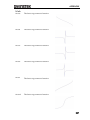
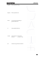
Table of Contents
Table of Contents
SAFETY INSTRUCTIONS .................................. 6
GETTING STARTED ........................................ 11
Main Features ................................................................... 11
Panel Overview .................................................................. 13
Setting Up the function Generator ..................................... 19
QUICK REFERENCE ....................................... 21
How to use the Digital Inputs ........................................... 23
How to use the Help Menu ............................................... 25
Selecting a Waveform ........................................................ 27
Modulation ........................................................................ 29
Sweep ................................................................................ 34
Burst ................................................................................. 35
ARB ................................................................................... 37
Utility Menu ...................................................................... 40
Frequency Counter ............................................................. 41
Coupling ............................................................................ 42
Menu Tree ......................................................................... 44
Default Settings ................................................................ 52
OPERATION ................................................... 54
Select a Waveform ............................................................. 55
MODULATION ............................................... 64
Amplitude Modulation (AM) ............................................. 66
Frequency Modulation (FM) .............................................. 75
Frequency Shift Keying (FSK) Modulation .......................... 84
Phase Modulation (PM) .................................................... 91
SUM modulation ............................................................. 100
Frequency Sweep ............................................................. 108
3
AFG-2225 User Manual
Burst Mode ..................................................................... 118
SECONDARY SYSTEM FUNCTION SETTINGS
..................................................................... 131
Save and Recall ............................................................... 132
System and Settings ........................................................ 136
System and Settings ........................................................ 136
CHANNEL SETTINGS .................................. 143
ARBITRARY WAVEFORMS ............................ 147
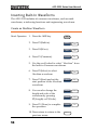
Inserting Built-In Waveforms ........................................... 148
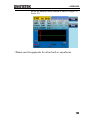
Display an Arbitrary Waveform ........................................ 150
Editing an Arbitrary Wavefrom ......................................... 159
Ouput an Arbitrary Waveform .......................................... 169
Saving/Loading an Arbitrary Waveform ............................ 171
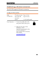
REMOTE INTERFACE ................................... 180
Establishing a Remote Connection .................................. 181
Command List ................................................................. 189
System Commands .......................................................... 193
Status Register Commands .............................................. 196
System Remote Commands ............................................. 199
Apply Commands ............................................................ 200
Output Commands .......................................................... 206
Pulse Configuration Commands ...................................... 216
Amplitude Modulation (AM) Commands ......................... 218
AM Overview ................................................................... 218
Frequency Modulation (FM) Commands .......................... 223
FM Overview ................................................................... 223
Frequency-Shift Keying (FSK) Commands ........................ 228
FSK Overview .................................................................. 228
Phase Modulation (PM)Commands ................................. 232
PM Overview ................................................................... 232
4
Table of Contents
SUM Modulation (SUM) Commands .............................. 236
SUM Overview ................................................................. 236
Frequency Sweep Commands .......................................... 240
Sweep Overview .............................................................. 240
Burst Mode Commands ................................................... 249
Burst Mode Overview ...................................................... 249
Arbitrary Waveform Commands ....................................... 260
Arbitrary Waveform Overview .......................................... 260
COUNTER ....................................................................... 266
PHASE ............................................................................. 267
COUPLE .......................................................................... 268
Save and Recall Commands ............................................. 271
Error Messages ............................................................... 273
SCPI Status Register ........................................................ 281
APPENDIX .................................................... 287
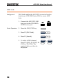
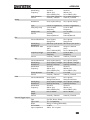
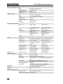
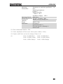
AFG-2225 Specifications .................................................. 287
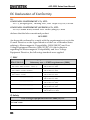
EC Declaration of Conformity .......................................... 292
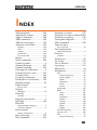
INDEX .......................................................... 305
5
AFG-2225 User Manual
SAFETY INSTRUCTIONS
This chapter contains important safety instructions
that should be followed when operating and
storing the function generator. Read the following
before any operation to ensure your safety and to
keep the function generator in the best condition.
Safety Symbols
These safety symbols may appear in this manual or on the
instrument.
WARNING
Warning: Identifies conditions or practices that
could result in injury or loss of life.
CAUTION
Caution: Identifies conditions or practices that
could result in damage to the function generator or
to other objects or property.
DANGER High Voltage
Attention: Refer to the Manual
Protective Conductor Terminal
Earth (Ground) Terminal
DANGER Hot Surface
6
SAFETY INSTRUCTIONS
Double Insulated
Do not dispose electronic equipment as unsorted
municipal waste. Please use a separate collection
facility or contact the supplier from which this
instrument was purchased.
Safety Guidelines
General
Guideline
CAUTION
Do not place heavy objects on the instrument.
Do not place flammable objects on the
instrument.
Avoid severe impact or rough handling that
may damage the function generator.
Avoid discharges of static electricity on or near
the function generator.
Use only mating connectors, not bare wires, for
the terminals.
The instrument should only be disassembled by
a qualified technician.
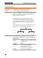
(Measurement categories) EN 61010-1:2010 specifies the
measurement categories and their requirements as follows. The
AFG-2225 falls under category II.
Measurement category IV is for measurement performed at the
source of a low-voltage installation.
Measurement category III is for measurement performed in a
building installation.
Measurement category II is for measurement performed on
circuits directly connected to a low voltage installation.
Measurement category I is for measurements performed on
circuits not directly connected to Mains.
Power Supply
WARNING
AC Input voltage: 100 ~ 240V AC, 50 ~ 60Hz.
Connect the protective grounding conductor of
the AC power cord to an earth ground to
prevent electric shock.
7
AFG-2225 User Manual
Fuse
WARNING
Cleaning the
function
generator
Operation
Environment
8
Fuse type: F1A/250V.
Only qualified technicians should replace the
fuse.
To ensure fire protection, replace the fuse only
with the specified type and rating.
Disconnect the power cord and all test leads
before replacing the fuse.
Make sure the cause of fuse blowout is fixed
before replacing the fuse.
Disconnect the power cord before cleaning the
function generator.
Use a soft cloth dampened in a solution of mild
detergent and water. Do not spray any liquid
into the function generator.
Do not use chemicals containing harsh products
such as benzene, toluene, xylene, and acetone.
Location: Indoor, no direct sunlight, dust free,
almost non-conductive pollution (Note below)
and avoid strong magnetic fields.
Relative Humidity: < 80%
Altitude: < 2000m
Temperature: 0°C to 40°C
SAFETY INSTRUCTIONS
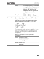
(Pollution Degree) EN 61010-1:2010specifies pollution degrees and
their requirements as follows. The function generator falls under
degree 2.
Pollution refers to “addition of foreign matter, solid, liquid, or
gaseous (ionized gases), that may produce a reduction of dielectric
strength or surface resistivity”.
Pollution degree 1: No pollution or only dry, non-conductive
pollution occurs. The pollution has no influence.
Pollution degree 2: Normally only non-conductive pollution
occurs. Occasionally, however, a temporary conductivity caused
by condensation must be expected.
Pollution degree 3: Conductive pollution occurs, or dry, nonconductive pollution occurs which becomes conductive due to
condensation which is expected. In such conditions, equipment
is normally protected against exposure to direct sunlight,
precipitation, and full wind pressure, but neither temperature
nor humidity is controlled.
Storage
environment
Disposal
Location: Indoor
Relative Humidity: < 70%
Temperature: -10°C to 70°C
Do not dispose this instrument as unsorted
municipal waste. Please use a separate collection
facility or contact the supplier from which this
instrument was purchased. Please make sure
discarded electrical waste is properly recycled to
reduce environmental impact.
9
AFG-2225 User Manual
Power cord for the United Kingdom
When using the function generator in the United Kingdom, make sure the
power cord meets the following safety instructions.
NOTE: This lead/appliance must only be wired by competent persons
WARNING: THIS APPLIANCE MUST BE EARTHED
IMPORTANT: The wires in this lead are coloured in accordance with the
following code:
Green/ Yellow:
Earth
Blue:
Neutral
Brown:
Live (Phase)
As the colours of the wires in main leads may not correspond with the
coloured marking identified in your plug/appliance, proceed as follows:
The wire which is coloured Green & Yellow must be connected to the Earth
terminal marked with either the letter E, the earth symbol
or coloured
Green/Green & Yellow.
The wire which is coloured Blue must be connected to the terminal which is
marked with the letter N or coloured Blue or Black.
The wire which is coloured Brown must be connected to the terminal
marked with the letter L or P or coloured Brown or Red.
If in doubt, consult the instructions provided with the equipment or contact
the supplier.
This cable/appliance should be protected by a suitably rated and approved
HBC mains fuse: refer to the rating information on the equipment and/or
user instructions for details. As a guide, a cable of 0.75mm2 should be
protected by a 3A or 5A fuse. Larger conductors would normally require
13A types, depending on the connection method used.
Any exposed wiring from a cable, plug or connection that is engaged in a
live socket is extremely hazardous. If a cable or plug is deemed hazardous,
turn off the mains power and remove the cable, any fuses and fuse
assemblies. All hazardous wiring must be immediately destroyed and
replaced in accordance to the above standard.
10
GETTING STARTED
GETTING STARTED
The Getting started chapter introduces the
function generator’s main features, appearance, set
up procedure and power-up.
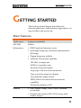
Main Features
Model name
Frequency bandwidth
AFG-2225
25MHz
Performance
DDS Function Generator series
1μHz high frequency resolution maintained at
full range
20ppm frequency stability
Arbitrary Waveform Capability
120 MSa/s sample rate
60 MSa/s repetition rate
4k-point waveform length
10 groups of 4k waveform memories
True waveform output to display
User-defined output section
DWR (Direct Waveform Reconstruction)
capability
Waveform editing via PC
Features
Sine, Square, Ramp, Pulse, Noise, standard
waveforms
Internal and external LIN/LOG sweep with
marker output
11
AFG-2225 User Manual
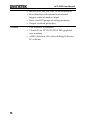
Interface
12
Int/Ext AM, FM, PM, FSK, SUM modulation
Burst function with internal and external
triggers without marker output
Store/recall 10 groups of setting memories
Output overload protection
USB interface as standard
3.5 inch Color TFT LCD (320 X 240) graphical
user interface
AWES (Arbitrary Waveform Editing Software)
PC software
GETTING STARTED
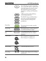
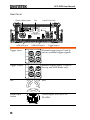
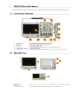
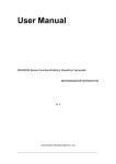
Panel Overview
Front Panel
LCD Display
Function keys, Scroll Wheel
Return key
Arrow keys
Output
Terminals
AFG-2225
/
turn
Number pad
LCD Display
Function Keys
F1~F5
Return Key
Operation Keys
Operation keys
Output key
Channel
select key
Power
switch
TFT color display, 320 x 240 resolution.
turn
Activates functions which appear
on the right-hand side of the LCD
display.
Goes back to the previous menu
level.
The waveform key is used to select
a type of waveform.
/
The FREQ/Rate key is used to set
the frequency or sample rate.
AMPL sets the waveform
amplitude.
Sets the DC offset.
13
AFG-2225 User Manual
The UTIL key is used to access the
save and recall options, update and
view the firmware version, access
the calibration options, output
impedance settings and frequency
meter.
ARB is used to set the arbitrary
waveform parameters.
The MOD, Sweep and Burst keys
are used to set the modulation,
sweep and burst settings and
parameters.
Preset Key
Output Key
Channel Select
Key
Output ports
The preset key is used to recall a
preset state.
The Output key is used to turn on
or off the waveform output.
The channel select key is used to
switch between the two output
channels.
CH1: Channel 1 output port
CH2: Channel 2 output port
Ω
Ω
Power Button
Turns the power on or off.
Arrow Keys
Used to select digits when editing
parameters.
14
GETTING STARTED
The scroll wheel is used to edit
values and parameters.
Scroll Wheel
Decrease
Keypad
Increase
The digital keypad is used to enter
values and parameters. The keypad
is often used in conjunction with
the arrow keys and variable knob.
/
15
AFG-2225 User Manual
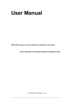
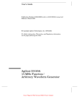
Rear Panel
Power socket input
Fan
Input Terminals
v
ost
rr
rr
ountr
z
USB Host port
Trigger Input
USB Device port
Trigger
MOD
Trigger
Counter
Trigger
MOD
Trigger
Counter
IN
Trigger output
External trigger input. Used to
receive external trigger signals.
OUT
Trigger Output
IN
Marker output signal. Used for
Sweep and ARB mode only.
OUT
Fan
Fan.
Power Input
Socket
Power input: 100~240V AC
50~60Hz.
AC 100-240V
50-60Hz 25W MAX
16
GETTING STARTED
USB Host
USB type-A host port.
Host
USB Device
Port
USB type-B device port is used to
connect the function generator to a
PC for remote control.
Device
Counter Input
Trigger
MOD
Trigger
Counter
Trigger
MOD
Trigger
Counter
Frequency counter input.
IN
OUT
MOD Input
Modulation input terminal.
IN
OUT
17
AFG-2225 User Manual
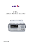
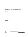
Display
Parameter
Windows
The Parameter display and edit window.
Status Tabs
Displays the current channel and setting status.
Waveform Display Used to display the waveform
Soft Menu Keys
18
The function keys (F1~F5) beside the Soft Menu
keys correspond to the soft keys.
GETTING STARTED
Setting Up the function Generator
Background
This section describes how to adjust the handle
and power up the function generator.
Adjusting the
Handle
Pull out the handle
sideways and rotate
it.
AFG-2225
/
turn
Place the AFG-2225
horizontally,
Or tilt the stand.
Place the handle
vertically to hand
carry.
19
AFG-2225 User Manual
Power Up
1. Connect the power cord to
the socket on the rear panel.
2. Turn on the power switch
on the front panel.
3. When the power switch is turned on the screen
displays the loading screen.
The function generator is now ready to be used.
20
QUICK REFERENCE
QUICK REFERENCE
This chapter describes the operation shortcuts, built-in help and
factory default settings. This chapter is to be used as a quick
reference, for detailed explanations on parameters, settings and
limitations, please see the operation chapters.
How to use the Digital Inputs ........................................... 23
How to use the Help Menu ............................................... 25
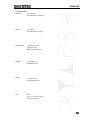
Selecting a Waveform ........................................................ 27
Square Wave ......................................................................... 27
Ramp Wave .......................................................................... 27
Sine Wave ............................................................................. 28
Modulation ........................................................................ 29
AM ........................................................................................ 29
FM ........................................................................................ 30
FSK Modulation.................................................................... 31
PM Modulation .................................................................... 32
SUM Modulation.................................................................. 33
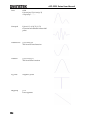
Sweep ................................................................................ 34
Burst ................................................................................. 35
ARB ................................................................................... 37
ARB–Add Built-In Waveform ................................................ 37
ARB- Add Point ..................................................................... 37
ARB- Add Line ...................................................................... 38
ARB– Output Section ........................................................... 38
Utility Menu ...................................................................... 40
Save ...................................................................................... 40
Recall .................................................................................... 40
Frequency Counter ............................................................. 41
Frequency Counter ............................................................... 41
Coupling ............................................................................ 42
Frequency Coupling ............................................................. 42
Amplitude Coupling ............................................................. 42
21
AFG-2225 User Manual
Tracking ................................................................................ 43
Menu Tree ......................................................................... 44
Waveform ............................................................................. 44
ARB-Display.......................................................................... 45
ARB-Edit ............................................................................... 46
ARB- Built In ......................................................................... 46
ARB-Save .............................................................................. 47
ARB-Load.............................................................................. 47
ARB-Output .......................................................................... 48
MOD .................................................................................... 48
SWEEP .................................................................................. 49
SWEEP- More ....................................................................... 49
Burst- N Cycle ...................................................................... 50
Burst – Gate ......................................................................... 50
UTIL ...................................................................................... 51
CH1/CH2 ............................................................................. 51
22
QUICK REFERENCE
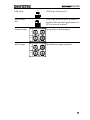
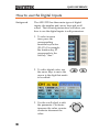
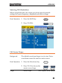
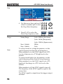
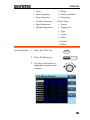
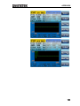
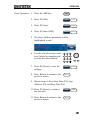
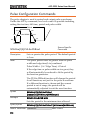
How to use the Digital Inputs
Background
The AFG-2225 has three main types of digital
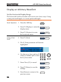
inputs: the number pad, arrow keys and scroll
wheel. The following instructions will show you
how to use the digital inputs to edit parameters.
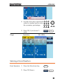
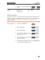
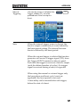
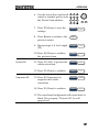
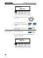
1. To select a menu
item, press the
corresponding
function keys below
(F1~F5). For example
the function key F1
corresponds to the
Soft key “Sine”.
2. To edit a digital value, use
the arrow keys to move the
cursor to the digit that needs
to be edited.
3. Use the scroll wheel to edit
the parameter. Clockwise
increases the value, counter
clockwise decreases the
value.
23
AFG-2225 Series User Manual
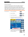
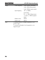
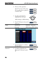
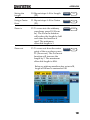
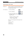
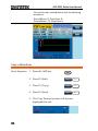
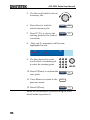
4. Alternatively, the number
pad can be used to set the
value of a highlighted
parameter.
24
/
APPENDIX
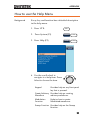
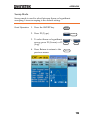
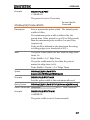
How to use the Help Menu
Background
Every key and function has a detailed description
in the help menu.
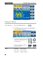
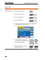
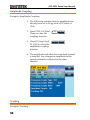
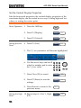
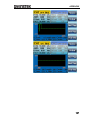
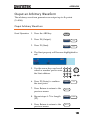
1. Press UTIL
2. Press System (F3)
3. Press Help (F2)
ystm
lp
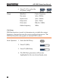
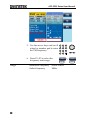
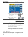
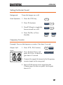
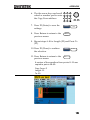
4. Use the scroll wheel to
navigate to a help item. Press
Select to choose the item.
Keypad
Provides help on any front panel
key that is pressed.
Create Arbitrary Provides help on creating
Waveform
arbitrary waveforms.
Modulation
Function
Explains how to create
Modulated waveforms.
Sweep Function Provides help on the Sweep
function.
25
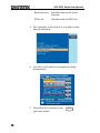
AFG-2225 Series User Manual
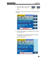
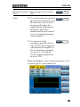
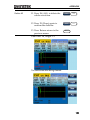
Burst Function
Provides help on the Burst
function.
DSO Link
Provides help on DSO link.
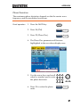
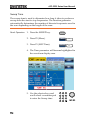
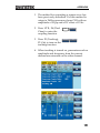
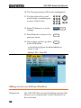
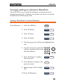
5. For example, select item 4 to see help on the
sweep functions.
6. Use the scroll wheel to navigate the help
information.
7. Press Return to return to the
previous menu.
26
Return
APPENDIX
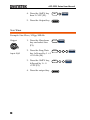
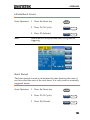
Selecting a Waveform
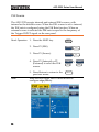
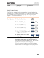
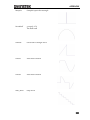
Square Wave
Example: Square wave, 3Vpp, 75% duty cycle, 1kHz.
Output:
CH1
50 Ω
Input: N/A
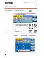
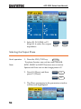
1. Press Waveform and
select Square (F2).
2. Press Duty (F1), 7 + 5
+ %(F2).
3. Press Freq/Rate, 1 +
kHz (F4).
4. Press AMPL followed
by, 3 + VPP (F5).
5. Press the Output key.
quar
uty
%
/
kz
OUTPUT
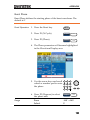
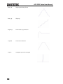
Ramp Wave
Example: Ramp Wave, 5Vpp, 10kHz, 50% Symmetry.
Output:
CH1
1. Press the Waveform
key, and select Ramp
(F4).
amp
50 Ω
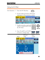
2. Press SYM(F1), 5 + 0
+%(F2).
Input: N/A
3. Press the Freq/Rate
key then 1 + 0 + kHz
(F4).
%
/
kz
27
AFG-2225 Series User Manual
4. Press the AMPL key
then 5 +VPP (F5).
5. Press the Output key.
OUTPUT
Sine Wave
Example: Sine Wave, 10Vpp,100kHz
Output:
CH1
1. Press the Waveform
key and select Sine
(F1).
n
50 Ω
Input: N/A
2. Press the Freq/Rate
key, followed by 1 + 0
+0 + kHz (F4).
3. Press the AMPL key,
followed by 1 + 0
+VPP (F5).
4. Press the output key.
28
/
OUTPUT
kz
APPENDIX
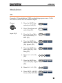
Modulation
AM
Example: AM modulation. 100Hz modulating square wave. 1kHz
Sine wave carrier. 80% modulation depth.
Output:
CH1
50 Ω
Input: N/A
1. Press the MOD key
and select AM (F1).
2. Press Waveform and
select Sine (F1).
3. Press the Freq/Rate
key, followed by 1 +
kHz (F4).
4. Press the MOD key,
select AM (F1), Shape
(F4), Square (F2).
n
/
7. Press the MOD key,
select AM (F1), Depth
(F2).
8. Press 8 + 0 + % (F1).
9. Press MOD, AM (F1),
Source (F1), INT (F1).
hap
rq
quar
5. Press the MOD key,
select AM (F1), AM
Freq (F3).
6. Press 1 + 0 + 0 + Hz
(F2).
kz
z
pth
%
our
29
AFG-2225 Series User Manual
10. Press the output key.
OUTPUT
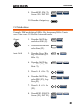
FM
Example: FM modulation. 100Hz modulating square wave. 1kHz
Sine wave carrier. 100 Hz frequency deviation. Internal Source.
Output:
CH1
50 Ω
Input: N/A
1. Press the MOD key
and select FM (F2).
2. Press Waveform and
select Sine (F1).
3. Press the Freq/Rate
key, followed by 1 +
kHz (F4).
4. Press the MOD key,
select FM (F2), Shape
(F4), Square (F2).
n
/
7. Press the MOD key,
select FM (F2), Freq
Dev (F2).
8. Press 1 + 0 + 0 + Hz
(F3).
30
hap
rq
quar
5. Press the MOD key,
select FM (F2), FM
Freq (F3).
6. Press 1 + 0 + 0 + Hz
(F2).
kz
z
rqv
z
APPENDIX
9. Press MOD, FM (F2),
Source (F1), INT (F1).
10. Press the Output key.
our
OUTPUT
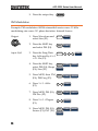
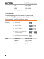
FSK Modulation
Example: FSK modulation. 100Hz Hop frequency. 1kHz Carrier
wave. Sine wave. 10 Hz Rate. Internal Source.
Output:
CH1
50 Ω
Input: N/A
1. Press the MOD key
and select FSK (F3).
2. Press Waveform and
select Sine (F1).
3. Press the Freq/Rate
key, followed by 1 +
kHz (F4).
K
n
/
4. Press the MOD key,
select FSK (F3), FSK
Rate (F3).
5. Press 1 + 0 + Hz (F2).
6. Press the MOD key,
select FSK (F3), Hop
Freq (F2).
7. Press 1 + 0 + 0 + Hz
(F3).
8. Press MOD, FSK (F3),
Source (F1), INT (F1).
K
kz
z
K
Kat
K
oprq
z
our
31
AFG-2225 Series User Manual
9. Press the output key.
OUTPUT
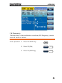
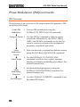
PM Modulation
Example: PM modulation. 800Hz sinusoidal carrier wave. 15 kHz
modulating sine wave. 50˚ phase deviation. Internal Source.
Output:
CH1
50 Ω
Input: N/A
1. Press Waveform and
select Sine (F1).
n
2. Press the MOD key
and select PM (F4).
3. Press the Freq/Rate
key, followed by 8 + 0
+ 0 + Hz (F3).
/
4. Press the MOD key,
select PM (F4), Shape
(F4), Sine (F1).
7. Press MOD, PM (F4),
PM Dev (F2).
8. Press 5 + 0 + Degree
(F1).
9. Press MOD, PM (F4),
Source (F1), INT (F1).
32
hap
rq
n
5. Press MOD, then PM
(F4), PM Freq (F3).
6. Press 1 + 5 + kHz
(F3).
kz
v
r
our
z
APPENDIX
10. Press the Output key.
OUTPUT
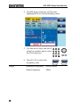
SUM Modulation
Example: SUM modulation. 100Hz modulating square wave, 1kHz
sinusoidal carrier wave, 50% SUM amplitude, internal source.
Output:
CH1
50 Ω
Input: N/A
1. Press the MOD key,
then SUM (F5).
2. Press Waveform, and
select Sine (F1).
3. Press Freq/Rate
followed by 1 + kHz
(F4).
4. Press the MOD key,
SUM (F5), Shape (F4),
Square (F2).
n
/
7. Press the MOD key
and select SUM (F5),
SUM Ampl (F2).
8. Press 5 + 0 + % (F1).
hap
rq
quar
5. Press the MOD key
and select SUM (F5),
SUM Freq (F3).
6. Press 1 + 0 + 0 + Hz
(F2).
kz
z
mpl
%
33
AFG-2225 Series User Manual
9. Press MOD, SUM
(F5), Source (F1), INT
(F1).
10. Press the Output key.
our
OUTPUT
Sweep
Example: Frequency Sweep. Start Frequency 10mHz, Stop frequency
1MHz. Log sweep, 1 second sweep, Marker Frequency 550 Hz,
Manual Trigger.
Output:
CH1
50 Ω
1. Press Sweep, Start
(F3).
2. Press 1 + 0 + mHz
(F2).
3. Press Sweep, Stop
(F4).
Input: N/A
4. Press 1 + MHz (F5).
5. Press Sweep, Type
(F2), Log (F2).
6. Press Sweep, More
(F5), SWP Time (F1).
7. Press 1 + SEC (F2).
8. Press Sweep, More
(F5), Marker (F4),
ON/OFF (F2), Freq
(F1).
34
mz
top
z
yp
o
or
m
or
arkr
rq
APPENDIX
9. Press 5 + 5 + 0 + Hz
(F3).
10. Press the Output key.
11. Press Sweep, Source
(F1), Manual (F3),
Trigger (F1).
z
OUTPUT
our
anual
rr
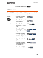
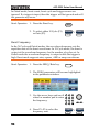
Burst
Example: Burst Mode, N-Cycle (Internally triggered), 1kHz burst
frequency, Burst count = 5, 10 ms Burst period, 0˚ burst phase,
Internal trigger, 10 us delay, rising edge trigger out
Output:
CH1
50 Ω
Input: N/A
1. Press FREQ/Rate 1
kHz (F4).
2. Press Burst, N Cycle
(F1), Cycles (F1).
3. Press 5 + Cyc (F2).
4. Press Burst, N Cycle
(F1), Period (F4).
5. Press 1 +0 + msec
(F2).
6. Press Burst, N Cycle
(F1), Phase (F3).
7. Press 0 + Degree (F2).
8. Press Burst, N Cycle
(F1), TRIG set (F5),
INT (F1).
/
yl
kz
yls
y
yl
rod
m
yl
has
r
yl
st
35
AFG-2225 Series User Manual
9. Press Burst, N Cycle
(F1), TRIG set (F5),
Delay (F4).
10. Press 1 + 0 + uSEC
(F2).
11. Press Burst, N Cycle
(F1), TRIG set (F5),
TRIG out (F5),
ON/OFF (F3), Rise
(F1).
12. Press the Output key.
36
yl
st
lay
u
yl
st
out
s
OUTPUT
APPENDIX
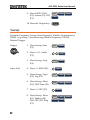
ARB
ARB–Add Built-In Waveform
Example: ARB Mode, Exponential Rise. Start 0, Length 100, Scale
327.
Output:
CH1
50 Ω
1. Press ARB, Built in
(F3), Wave (F4),
Math(F2), use the
scroll wheel to select
Exporise and then
press Select(F5).
ultn
ath
lt
tart
nth
ntr
ntr
2. Press Start (F1), 0 +
Enter (F2), Return.
3. Press Length (F2),
100, Enter (F2),
Return.
4. Press Scale (F3), 327,
Enter (F2), Return,
Done (F5).
av
ntr
Return
Return
al
Return
on
ARB- Add Point
Example: ARB Mode, Add point, Address 40, data 300.
Output:
CH1
1. Press ARB, Edit (F2),
Point (F1), Address
(F1)
dt
ont
ntr
Return
drss
50 Ω
2. Press 4 + 0 + Enter
(F2), Return
37
AFG-2225 Series User Manual
3. Press Data (F2),
3+0+0, Enter (F2).
ata
ntr
ARB- Add Line
Example: ARB Mode, Add line, Address:Data (10:30, 50:100)
Output:
CH1
1. Press ARB, Edit (F2),
Line (F2), Start ADD
(F1).
dt
n
ntr
Return
tart
50 Ω
2. Press 1 + 0 + Enter
(F2), Return.
3. Press Start Data (F2),
3 + 0, Enter (F2),
Return.
4. Press Stop ADD (F3),
5 + 0, Enter (F2),
Return.
5. Press Stop Data (F4),
1 + 0 + 0, Enter (F2),
Return, Done (F5).
tartata
ntr
ntr
Return
top
Return
topata
ntr
Return
on
ARB– Output Section
Example: ARB Mode, Output ARB Waveform, Start 0, Length 1000.
Output:
CH1
50 Ω
38
1. Press ARB, Output
(F4).
2. Press Start (F1), 0 +
Enter (F2), Return.
utput
tart
Return
ntr
APPENDIX
3. Press Length (F2), 1 +
0 + 0, Enter (F2),
Return.
nth
ntr
Return
39
AFG-2225 Series User Manual
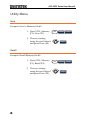
Utility Menu
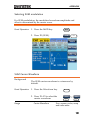
Save
Example: Save to Memory file #5.
1. Press UTIL, Memory
(F1), Store (F1).
2. Choose a setting
using the scroll wheel
and press Done (F5).
mory
tor
on
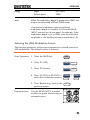
Recall
Example: Recall Memory file #5.
1. Press UTIL, Memory
(F1), Recall (F2).
2. Choose a setting
using the scroll wheel
and press Done (F5).
40
mory
on
all
APPENDIX
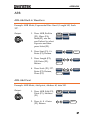
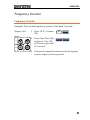
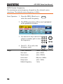
Frequency Counter
Frequency Counter
Example: Turn on the frequency counter. Gate time: 1 second.
1. Press UTIL, Counter
(F5).
Output: N/A
ountr
atm
Input:
Trigger
MOD
Trigger
Counter
IN
OUT
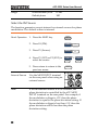
2. Press Gate Time (F1),
and press 1 Sec (F3)
to choose a gate time
of 1 second.
3. Connect the signal of interest to the Frequency
counter input on the rear panel.
41
AFG-2225 Series User Manual
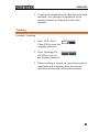
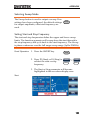
Coupling
Frequency Coupling
Example: Frequency Coupling
1. Press UTIL, Dual
Chan (F4) to enter the
coupling function.
2. Press Freq Cpl (F1) to
select the frequency
coupling function.
3. Press Offset (F2). The
offset is the frequency
difference between
CH1 and CH2. Use
the number keys or
scroll wheel to enter
the offset.
ualhan
rqpl
ffst
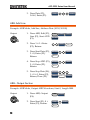
Amplitude Coupling
Example: Amplitude Coupling
1. Press UTIL, Dual
Chan (F4) to enter the
coupling function.
2. Press Ampl Cpl (F2),
ON (F1) to select the
amplitude coupling
function.
42
ualhan
mplpl
n
APPENDIX
3. Couples the amplitude and offset between both
channels. Any changes in amplitude in the
current channel are reflected in the other
channel.
Tracking
Example: Tracking
1. Press UTIL, Dual
Chan (F4) to enter the
coupling function.
2. Press Tracking (F3),
ON (F2) to turn on
the tracking function.
ualhan
rakn
n
3. When tracking is turned on, parameters such as
amplitude and frequency from the current
channel are mirrored on the other channel.
43
AFG-2225 Series User Manual
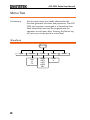
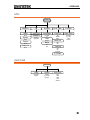
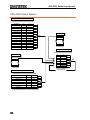
Menu Tree
Conventions
Use the menu trees as a handy reference for the
function generator functions and properties. The AFG2225 menu system is arranged in a hierarchical tree.
Each hierarchical level can be navigated with the
operation or soft menu keys. Pressing the Return key
will return you to the previous menu level.
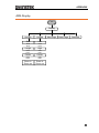
Waveform
Waveform
Sine
44
Square
Pulse
Ramp
Duty
%
TTL
Width
nSEC
uSEC
mSEC
SEC
SYM
%
Noise
APPENDIX
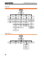
ARB-Display
Display
Horizon
Vertical
Start
Low
Clear
Enter
Clear
Enter
Length
High
Clear
Enter
Clear
Enter
Center
Center
Clear
Enter
Clear
Enter
Zoom in
Zoom out
Zoom in
Zoom out
Next Page
Back Page
Overview
45
AFG-2225 Series User Manual
ARB-Edit
Edit
Point
Line
Copy
Clear
Address
Start ADD
Start
Start
All
Clear
Enter
Clear
Enter
Clear
Enter
Clear
Enter
Done
Data
Start Data
Length
Length
Clear
Enter
Clear
Enter
Clear
Enter
Clear
Enter
Stop ADD
Paste To
Clear
Enter
Clear
Enter
Done
All
Stop Data
Done
Done
Clear
Enter
Protect
Start
Clear
Enter
Length
Clear
Enter
Done
Unprotect
Done
Done
ARB- Built In
Built in
46
Start
Length
Scale
Clear
Enter
Clear
Enter
Clear
Enter
Wave
Common
Math
Window
Engineer
Select
Done
APPENDIX
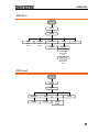
ARB-Save
More
Save
Start
Length
Clear
Enter
Clear
Enter
Memory
USB
Done
Select
Select
New Folder
Enter Char
Back Space
Save
New File
Enter Char
Back Space
Save
ARB-Load
More
Load
Memory
USB
To
Select
Select
Clear
Enter
Done
47
AFG-2225 Series User Manual
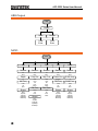
ARB-Output
Output
Start
Length
Clear
Enter
Clear
Enter
MOD
AM
FM
FSK
PM
SUM
Source
Source
Source
Source
Source
Int
EXT
Int
EXT
Int
EXT
Int
EXT
Int
EXT
Depth
Freq Dev
Hop Freq
Phase Dev
SUM Ampl
%
uHz
mHz
Hz
kHz
MHz
uHz
mHz
Hz
kHz
MHz
Degree
%
PM Freq
SUM Freq
FM Freq
FSK Rate
mHz
Hz
kHz
mHz
Hz
kHz
mHz
Hz
kHz
mHz
Hz
kHz
MHz
Shape
Shape
Sine
Square
Triangle
UpRamp
DnRamp
Sine
Square
Triangle
UpRamp
DnRamp
AM Freq
mHz
Hz
kHz
Shape
Sine
Square
Triangle
UpRamp
DnRamp
48
Shape
Sine
Square
Triangle
UpRamp
DnRamp
APPENDIX
SWEEP
Source
Type
Start
Stop
More
Int
EXT
Manual
Linear
Log
uHz
mHz
Hz
kHz
MHz
uHz
mHz
Hz
kHz
MHz
Go to the
Sweep More menu
Trigger
SWEEP- More
wp
More
SWP Time
Span
Center
Marker
mSEC
SEC
uHz
mHz
Hz
kHz
MHz
uHz
mHz
Hz
kHz
MHz
Freq
uHz
mHz
Hz
kHz
MHz
ON/OFF
49
AFG-2225 Series User Manual
Burst- N Cycle
urst
N Cycle
Cycles
Infinite
Clear
Cyc
Phase
Period
TRIG Setup
Clear
Degree
uSEC
mSEC
SEC
Int
EXT
Rise
Fall
Manual
Trigger
Delay
nSEC
uSEC
mSEC
SEC
TRIG out
Rise
Fall
ON/OFF
Burst – Gate
urst
Gate
50
Polarity
Phase
Pos
Neg
Clear
Degree
APPENDIX
UTIL
Memory
Cal.
System
Dual Chan
Counter
Store
Self Test
Software
Language
Freq Cpl
Gate Time
English
中文
0.01 Sec
0.1 Sec
1 Sec
10 Sec
Done
Recall
Done
Version
Upgrade
Delete
Done
Help
Off
Offset
Ratio
Select
Ampl Cpl
Beep
Off
On
On
Off
Delete All
Done
Tracking
Off
On
Inverted
S_Phase
CH1/CH2
CH1/CH2
Load
Phase
DSO Link
50 OHM
High Z
Phase
S_Phase
Degree
CH1
CH2
CH3
CH4
Search
51
AFG-2225 Series User Manual
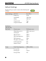
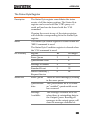
Default Settings
The Preset key is used to restore the default panel
settings.
Output Settings
rst
Function
Sine Wave
Frequency
1kHz
Amplitude
3.000 Vpp
Offset
0.00V dc
Output units
Vpp
Output terminal
50Ω
Carrier wave
1kHz sine wave
Modulation wave
100Hz sine wave
AM depth
100%
FM deviation
100Hz
FSK hop frequency
100Hz
FSK frequency
10Hz
PM phase deviation
180˚
SUM amplitude
50%
Modem status
Off
Start/Stop frequency
100Hz/1kHz
Sweep time
1s
Sweep type
Linear
Sweep status
Off
Modulation
(AM/FM/FSK/
PM/SUM)
Sweep
52
APPENDIX
Burst frequency
1kHz
Ncycle
1
Burst period
10ms
Burst starting phase
0˚
Burst status
Off
Power off signal
On
Display mode
On
Error queue
Cleared
Memory settings
No change
Output
Off
Trigger
Trigger source
Internal (immediate)
Calibration
Calibration Menu
Restricted
Burst
System Settings
53
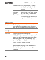
AFG-2225 Series User Manual
OPERATION
The Operation chapter shows how to output basic waveform
functions. For details on modulation, sweep, burst and arbitrary
waveforms, please see the Modulation and Arbitrary waveform
chapters on pages 64 and 147.
Select a Waveform ............................................................. 55
Sine Wave ............................................................................. 55
Square Wave ........................................................................ 56
Setting the Pulse Width ....................................................... 57
Setting a Ramp Waveform ................................................... 58
Selecting a Noise Waveform................................................ 59
Setting the Frequency .......................................................... 60
Setting the Amplitude .......................................................... 62
Setting the DC Offset ........................................................... 63
54
APPENDIX
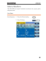
Select a Waveform
The AFG-2225 can output 5 standard waveforms: sine, square, pulse,
ramp and noise.
Sine Wave
Panel Operation
1. Press the Waveformkey.
2. Press F1 (Sine).
n
55
AFG-2225 Series User Manual
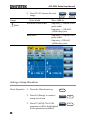
Square Wave
Panel Operation
1. Press the Waveform key.
2. Press F2 (Square) to create a
square waveform.
3. Press F1 (Duty). The Duty
parameter will be highlighted
in the parameter window.
4. Use the arrow keys and scroll
wheel or number pad to enter
the Duty range.
quar
uty
5. Press F2 (%) to select % units.
Range
/
%
Frequency
Duty Range
≤100kHz
1.0%~99.0%
100kHz~≤1MHz
10.0%~90.0%
>1MHz~25MHz
50% (Fixed)
TTL function is to set the amplitude of the current square wave at
2.5Vpp,and DC Offset at 1.25Vdc.
56
APPENDIX
Setting the Pulse Width
Panel Operation
1. Press the Waveform key.
2. Press F3 (Pulse) to create a
pulse width waveform.
3. Press F1 (Width). The Width
parameter will be highlighted
in the parameter window.
4. Use the arrow keys and scroll
wheel or number pad to enter
the pulse width.
uls
dth
/
57
AFG-2225 Series User Manual
5. Press F2~F5 choose the unit
range.
Range
Note
Pulse Width
Minimum Pulse Width
n
~
20ns~1999.9s
Frequency ≤ 25MHz: 20ns
pulse width.
Frequency ≤ 100 kHZ:
1/4096 duty cycle.
Resolution
Frequency ≤ 25MHz: 20ns
pulse width.
Frequency ≤100 kHZ:
1/4096 duty cycle.
Setting a Ramp Waveform
Panel Operation
1. Press the Waveform key.
2. Press F4 (Ramp) to create a
ramp waveform.
3. Press F1 (SYM). The SYM
parameter will be highlighted
in the parameter window.
58
amp
APPENDIX
4. Use the arrow keys and scroll
wheel or number pad to enter
the symmetry percentage.
5. Press F2 (%) to choose %
units.
Range
Symmetry
/
%
0%~100%
Selecting a Noise Waveform
Panel Operation
1. Press the Waveform key.
2. Press F5 (Noise).
os
59
AFG-2225 Series User Manual
Setting the Frequency
Panel Operation
1. Press the FREQ/Rate key.
/
2. The FREQ parameter will become highlighted
in the parameter window.
3. Use the arrow keys and scroll
wheel or number pad to enter
the frequency.
4. Choose a frequency unit by
pressing F1~F5.
Range
Sine wave
1μHz~25MHz
Square wave 1μHz~25MHz
Pulse wave
60
500μHz~25MHz
/
uz
~
z
APPENDIX
Ramp wave
1μHz~1MHz
61
AFG-2225 Series User Manual
Setting the Amplitude
Panel Operation
1. Press the AMPL key.
2. The AMPL parameter will become highlighted
in the parameter window.
3. Use the arrow keys and scroll
wheel or number pad to enter
the amplitude.
4. Choose a unit type by
pressing F1~F5.
62
/
dm
~
50Ω load
High Z
Range
1mVpp~10Vpp
2mVpp~20Vpp
Unit
Vpp, Vrms, dBm
APPENDIX
Setting the DC Offset
Panel Operation
1. Press the DC Offset key.
2. The DC Offset parameter will become
highlighted in the parameter window.
3. Use the arrow keys and scroll
wheel or number pad to enter
the DC Offset.
4. Press F1 (mVDC) or F2 (VDC)
to choose a voltage range.
Range
/
m
50Ω load
High Z
±5Vpk
±10Vpk
63
AFG-2225 Series User Manual
MODULATION
The AFG-2225 Series Arbitrary Function Generators are able to
produce AM, FM, FSK, PM and SUM modulated waveforms.
Depending on the type of waveform produced, different modulation
parameters can be set. Only one modulation mode can be active at
any one time. The function generator also will not allow sweep or
burst mode to be used with AM/FM. Activating a modulation mode
will turn the previous modulation mode off.
Amplitude Modulation (AM) ............................................. 66
Selecting AM Modulation .................................................... 67
AM Carrier Shape ................................................................. 67
Carrier Frequency ................................................................. 68
Modulating Wave Shape ...................................................... 69
AM Frequency ...................................................................... 70
Modulation Depth ............................................................... 72
Selecting the (AM) Modulation Source ............................... 73
Frequency Modulation (FM) .............................................. 75
Selecting Frequency Modulation (FM) ................................ 76
FMCarrier Shape .................................................................. 76
FM Carrier Frequency .......................................................... 77
FM Wave Shape ................................................................... 78
FM Frequency ...................................................................... 79
Frequency Deviation ............................................................ 81
Selecting (FM) Modulation Source ..................................... 82
Frequency Shift Keying (FSK) Modulation .......................... 84
Selecting FSK Modulation ................................................... 85
FSK Carrier Shape ................................................................ 85
FSK Carrier Frequency ......................................................... 86
FSK Hop Frequency ............................................................. 87
FSK Rate ............................................................................... 88
FSK Source ........................................................................... 90
Phase Modulation (PM) .................................................... 91
Selecting Phase Modulation (PM) ...................................... 92
PM Carrier Waveform .......................................................... 93
PM Carrier Frequency .......................................................... 93
64
APPENDIX
PM Wave Shape ................................................................... 94
PM Frequency....................................................................... 95
Phase Deviation ................................................................... 97
Select the PM Source ........................................................... 98
SUM modulation ............................................................. 100
Selecting SUM modulation ................................................ 101
SUM Carrier Waveform ...................................................... 101
SUM Carrier Frequency ...................................................... 102
SUM Waveform .................................................................. 103
Modulating Waveform Frequency ..................................... 104
SUM Amplitude.................................................................. 105
Select the SUM Amplitude Source .................................... 106
Frequency Sweep ............................................................. 108
Selecting Sweep Mode ....................................................... 109
Setting Start and Stop Frequency ...................................... 109
Center Frequency and Span ............................................... 111
Sweep Mode ....................................................................... 113
Sweep Time ........................................................................ 114
Marker Frequency............................................................... 115
Sweep Trigger Source......................................................... 116
Burst Mode ..................................................................... 118
Selecting Burst Mode ......................................................... 119
Burst Modes ....................................................................... 119
Burst Frequency ................................................................. 120
Burst Cycle/Burst Count .................................................... 121
Infinite Burst Count ............................................................ 123
Burst Period ........................................................................ 123
Burst Phase ........................................................................ 125
Burst Trigger Source .......................................................... 126
Burst Delay ......................................................................... 128
Burst Trigger Output .......................................................... 129
65
AFG-2225 Series User Manual
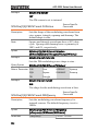
Amplitude Modulation (AM)
An AM waveform is produced from a carrier waveform and a
modulating waveform. The amplitude of the modulated carrier
waveform depends on the amplitude of the modulating waveform.
The AFG-2225 function generator can set the carrier frequency,
amplitude and offset as well as internal or external modulation
sources.
66
APPENDIX
Selecting AM Modulation
Panel Operation
1. Press the MOD key.
2. Press F1 (AM).
AM Carrier Shape
Background
Sine, square, ramp, pulse or arbitrary waveforms
can be used as the carrier shape. The default
waveform shape is set to sine. Noise is not
available as a carrier shape. Before the carrier
shape can be selected, choose AM modulation
mode, see above.
Select a Standard 1. Press the Waveform key.
Carrier Shape
2. Press F1~F4 to choose the
carrier wave shape.
n
~
amp
67
AFG-2225 Series User Manual
Select an
3. See the Arbitrary waveform Page 37
Arbitrary
quick reference or chapter to Page 147
Waveform Carrier
use an arbitrary waveform.
Shape.
Range
AM Carrier Shape
sine, square, Ramp,Pulse,
arbitrary waveform
Carrier Frequency
The maximum carrier frequency depends on the carrier shape
selected. The default carrier frequency for all carrier shapes is 1kHz.
Panel Operation
1. With a carrier waveform
selected, press the
FREQ/Rate key.
/
2. The FREQ parameter will become highlighted
in the parameter window.
3. Use the arrow keys and scroll
wheel or number pad to enter
the carrier frequency.
68
/
APPENDIX
4. Press F1~F5 to select the
frequency range.
Range
uz
~
z
Carrier Shape
Carrier Frequency
Sine wave
1μHz~ 25MHz
Square wave
1μHz~25MHz
Ramp wave
1μHz~1MHz
Pulse wave
500uHz~25MHz
Default frequency
1 kHz
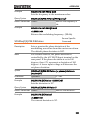
Modulating Wave Shape
The function generator can accept internal as well as external
sources. The AFG-2225 has sine, square, triangle, up ramp and down
ramp modulating waveform shapes. Sine waves are the default
wave shape.
Panel Operation
1. Press the MOD key.
2. Press F1 (AM).
3. Press F4 (Shape).
4. Press F1 ~ F5 to select the
waveform shape.
5. Press Return to return to the
previous menu.
Note
hap
n
~
namp
Return
Square wave
50% Duty cycle
UpRamp
100% Symmetry
Triangle
50% Symmetry
DnRamp
0% Symmetry
69
AFG-2225 Series User Manual
AM Frequency
The frequency of the modulation waveform (AM Frequency) can be
set from 2mHz to 20kHz.
Panel Operation
1. Press the MOD key.
2. Press F1 (AM).
3. Press F3 (AM Freq)
rq
4. The AM Freq parameter will become
highlighted in the Waveform display area.
70
APPENDIX
5. Use the arrow keys and scroll
wheel or number pad to enter
the AM frequency.
6. Press F1~F3 to select the
frequency range.
Range
/
mz
Modulation frequency
2mHz~20kHz
Default frequency
100Hz
~
kz
71
AFG-2225 Series User Manual
Modulation Depth
Modulation depth is the ratio (as a percentage) of the unmodulated
carrier amplitude and the minimum amplitude deviation of the
modulated waveform. In other words, modulation depth is the
maximum amplitude of the modulated waveform compared to the
carrier waveform as a percentage.
Panel Operation
1. Press the MOD key.
2. Press F1 (AM).
3. Press F2 (Depth).
pth
4. The AM Depth parameter will become
highlighted in the waveform display area.
5. Use the arrow keys and scroll
wheel or number pad to enter
the AM depth.
6. Press F1 (%) to choose %
units.
72
/
%
APPENDIX
Range
Note
Depth
0%~120%
Default depth
100%
When the modulation depth is greater than 100%, the
output cannot exceed ±5VPeak (10kΩ load).
If an external modulation source is selected,
modulation depth is limited to ± 5V from the MOD
INPUT terminal on the rear panel. For example, if the
modulation depth is set to 100%, then the maximum
amplitude is +5V, and the minimum amplitude is -5V.
Selecting the (AM) Modulation Source
The function generator will accept an internal or external source for
AM modulation. The default source is internal.
Panel Operation
1. Press the MOD key.
2. Press F1 (AM).
3. Press F1 (Source).
4. Press F1 (INT) or F2 (EXT) to
select the modulation source.
5. Press Return to go back to the
previous menu.
External Source
Use the MOD INPUT terminal
on the rear panel when using an
external source.
our
~
Return
Trigger
MOD
Trigger
Counter
IN
OUT
73
AFG-2225 Series User Manual
Note
74
If an external modulation source is selected,
modulation depth is limited to ± 5V from the MOD
INPUT terminal on the rear panel. For example, if
modulation depth is set to 100%, then the maximum
amplitude is +5V, and the minimum amplitude is -5V.
APPENDIX
Frequency Modulation (FM)
A FM waveform is produced from a carrier waveform and a
modulating waveform. The instantaneous frequency of the carrier
waveform varies with the magnitude of the modulating waveform.
When using the AFG-2225 function generator, only one type of
modulated waveform can be created at any one time.
75
AFG-2225 Series User Manual
Selecting Frequency Modulation (FM)
When FM is selected, the modulated waveform depends on the
carrier frequency, the output amplitude and offset voltage.
Panel Operation
1. Press the MOD key.
2. Press F2 (FM).
FMCarrier Shape
Background
The default waveform shape is set to sine. Noise
and pulse waveforms cannot be used as a carrier
wave.
Panel Operation
1. Press the Waveform key.
2. Press F1~F4 to select the
carrier shape.
Range
76
Carrier Shape
n
~
Sine, Square, Ramp.
amp
APPENDIX
FM Carrier Frequency
When using the AFG-2225 function generator, the carrier frequency
must be equal to or greater than the frequency deviation. If the
frequency deviation is set to value greater than the carrier frequency,
the deviation is set to the maximum allowed. The maximum
frequency of the carrier wave depends on the waveform shape
chosen.
Panel Operation
1. To select the carrier
frequency, press the
FREQ/Rate key.
at
2. The FREQ parameter will become highlighted
in the parameter window.
3. Use the arrow keys and scroll
wheel or number pad to enter
the carrier frequency.
4. Press F1~F5 to select the
frequency unit.
Range
Carrier Shape
/
uz
~
z
Carrier Frequency
77
AFG-2225 Series User Manual
Sine
1μHz~25MH
Square
1μHz~15MHz
Ramp
1μHz~1MHz
Default frequency
1kHz
FM Wave Shape
The function generator can accept internal as well as external
sources. The AFG-2225 has sine, square, triangle, positive and
negative ramps (UpRamp, DnRamp) as the internal modulating
waveform shapes. Sine is the default wave shape.
Background
1. Select MOD.
2. Press F2 (FM).
3. Press F4 (Shape).
4. Press F1 ~ F5 to select the
waveform shape.
5. Press Return to return to the
previous menu.
Range
78
hap
n
Return
Square wave
50% Duty cycle
UpRamp
100% Symmetry
Triangle
50% Symmetry
DnRamp
0% Symmetry
~
namp
APPENDIX
FM Frequency
The frequency of the modulation waveform (FM Frequency) can be
set from 2mHz to 20kHz.
Panel Operation
1. Press the MOD key.
2. Press F2 (FM).
3. Press F3 (FM Freq).
rq
79
AFG-2225 Series User Manual
4. The FM Freq parameter will become
highlighted in waveform display panel.
5. Use the arrow keys and scroll
wheel or number pad to enter
the FM frequency.
6. Press F1~F3 to select the
frequency unit.
Range
80
/
mz
Modulation frequency
2mHz~20kHz
Default frequency
100Hz
~
kz
APPENDIX
Frequency Deviation
The frequency deviation is the peak frequency deviation from the
carrier wave and the modulated wave.
Panel Operation
1. Press the MOD key.
2. Press F2 (FM).
3. Press F2 (Freq Dev).
rqv
4. The Freq Dev parameter will become
highlighted in the waveform display panel.
5. Use the arrow keys and scroll
wheel or number pad to enter
the frequency deviation.
6. Press F1~ F5 to choose the
frequency units.
/
uz
~
z
81
AFG-2225 Series User Manual
Range
Frequency Deviation
DC~25MHz
DC~15MHz(square)
DC~1MHz (Ramp)
Default depth
100Hz
Selecting (FM) Modulation Source
The function generator will accept an internal or external source for
FM modulation. The default source is internal.
Panel Operation
1. Press the MOD key.
2. Press F2 (FM).
3. Press F1 (Source).
4. To select the source, press F1
(Internal) or F2 (External).
5. Press Return to return to the
previous menu.
External Source
Use the MOD INPUT terminal
on the rear panel when using an
external source.
our
~
Return
Trigger
MOD
Trigger
Counter
IN
OUT
82
APPENDIX
Note
If an external modulating source is selected, the
frequency deviation is limited to the ± 5V MOD
INPUT terminal on the rear panel. The frequency
deviation is proportional to the signal level of the
modulation in voltage. For example, if the
modulation in voltage is +5V, then the frequency
deviation would be equal to the set frequency
deviation. Lower signal levels reduce the
frequency deviation while negative voltage levels
produce frequency deviations with frequencies
below the carrier waveform.
83
AFG-2225 Series User Manual
Frequency Shift Keying (FSK) Modulation
Frequency Shift Keying Modulation is used to shift the frequency
output of the function generator between two preset frequencies
(carrier frequency, hop frequency). The frequency at which the
carrier and hop frequency shift is determined by the internal rate
generator or the voltage level from the Trigger INPUT terminal on
the rear panel.
Only one modulation mode can be used at once. When FSK
modulation is enabled, any other modulation modes will be
disabled. Sweep and Burst also cannot be used with FSK modulation.
Enabling FSK will disable Sweep or Burst mode.
84
APPENDIX
Selecting FSK Modulation
When using FSK mode, the output waveform uses the default
settings for carrier frequency, amplitude and offset voltage.
Panel Operation
1. Press the MOD key.
2. Press F3 (FSK).
K
FSK Carrier Shape
Background
The default waveform shape is set to sine. Noise
waveforms cannot be used as carrier waves.
Panel Operation
1. Press the Waveform key.
2. Press F1~F4 to choose the
carrier wave shape.
Range
Carrier Shape
n
~
amp
Sine, Square, Pulse, Ramp
85
AFG-2225 Series User Manual
FSK Carrier Frequency
The maximum carrier frequency depends on the carrier shape. The
default carrier frequency for all carrier shapes is 1kHz. The voltage
level of the Trigger INPUT signal controls the output frequency
when EXT is selected. When the Trigger INPUT signal is logically
low the carrier frequency is output and when the signal is logically
high, the hop frequency is output.
Panel Operation
1. Press the FREQ/Rate key to
select the carrier frequency.
/
2. The FREQ parameter will become highlighted
in the parameter window.
3. Use the arrow keys and scroll
wheel or number pad to enter
the carrier frequency.
4. Press F1~F5 to select the FSK
frequency units.
Range
86
/
uz
~
Carrier Shape
Carrier Frequency
Sine wave
1μHz~25MHz
Square wave
1μHz~15MHz
Ramp wave
1μHz~1MHz
Pulse wave
500μHz~15MHz
Default frequency
1kHz
z
APPENDIX
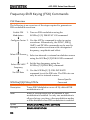
FSK Hop Frequency
The default Hop frequency for all waveform shapes is 100 Hz. A
square wave with a duty cycle of 50% is used for the internal
modulation waveform. The voltage level of the Trigger INPUT
signal controls the output frequency when EXT is selected. When the
Trigger INPUT signal is logically low the carrier frequency is output
and when the signal is logically high, the hop frequency is output.
Panel Operation
1. Press the MOD key.
2. Press F3 (FSK).
K
oprq
3. Press F2 (Hop Freq).
4. The Hop Freq parameter will become
highlighted in the Waveform Display area.
5. Use the arrow keys and scroll
wheel or number pad to enter
the hop frequency.
/
87
AFG-2225 Series User Manual
6. Press F1~F5 to select the
frequency range.
Range
uz
~
z
Waveform
Carrier Frequency
Sine wave
1μHz~25MHz
Square wave
1μHz~15MHz
Ramp wave
1μHz~1MHz
Pulse wave
500μHz~15MHz
Default frequency
100Hz
FSK Rate
FSK Rate function is used to determine rate at which the output
frequency changes between the carrier and hop frequencies. The
FSK Rate function only applies to internal FSK sources.
Panel Operation
1. Select the MOD key.
2. Press F3 (FSK).
K
Kat
3. Press F3 (FSK Rate).
4. The FSK Rate parameter will become
highlighted in the waveform display area.
88
APPENDIX
5. The arrow keys and scroll
wheel or number pad to enter
the FSK rate.
6. Press F1~F4 to select the
frequency unit.
Range
Note
/
mz
FSK Rate
2mHz~100kHz
Default
10Hz
~
kz
If an external source is selected, FSK Rate settings are
ignored.
89
AFG-2225 Series User Manual
FSK Source
The AFG-2225 accepts internal and external FSK sources, with
internal as the default source. When the FSK source is set to internal,
the FSK rate is configured using the FSK Rate function. When an
external source is selected the FSK rate is equal to the frequency of
the Trigger INPUT signal on the rear panel.
Panel Operation
1. Press the MOD key.
2. Press F3 (FSK).
K
our
3. Press F1 (Source).
4. Press F1 (Internal) or F2
(External) to select the FSK
source.
5. Press Return to return to the
previous menu.
Note
90
~
Return
Note that the Trigger INPUT terminal cannot
configure edge polarity.
APPENDIX
Phase Modulation (PM)
The phase deviation of the carrier waveform deviates from a
reference phase value in proportion to changes in the modulating
waveform.
Only one mode of modulation can be enabled at any one time. If PM
is enabled, any other modulation mode will be disabled. Likewise,
burst and sweep modes cannot be used with PM and will be
disabled when PM is enabled.
91
AFG-2225 Series User Manual
Selecting Phase Modulation (PM)
When selecting PM, the current setting of the carrier frequency, the
amplitude modulation frequency, output, and offset voltage must be
considered.
Panel Operation
1. Press the MOD key.
2. Press F4 (PM).
92
APPENDIX
PM Carrier Waveform
Background
PM uses a sine wave as default. Noise and Pulse
waveform cannot be used with phase modulation.
Panel Operation
1. Press the Waveform key.
2. Press F1 ~ F4 to select the
waveform.
Range
Carrier Waveform
n
~
amp
Sine wave, Square wave,
ramp wave.
PM Carrier Frequency
Selects the maxium carrier frequency for the carrier wavefrom. The
default carrier frequency is 1kHz.
Panel Operation
1. Press the FREQ/Rate key to
select the carrier frequency.
/
2. The FREQ parameter will become highlighted
in the parameter window.
3. Use the arrow keys and scroll
wheel or number pad to enter
the carrier frequency.
/
93
AFG-2225 Series User Manual
4. Press F1~F5 to select the
frequency unit.
Range
uz
~
z
Carrier Wave
Carrier Frequency
Sine wave
1μHz~25MH
Square wave
1μHz~15MHz
Ramp wave
1μHz~1MHz
Default frequency
1 kHz
PM Wave Shape
The function generator can accept internal or external sources. The
internal sources can include sine, square, triangle, up ramp and
down ramp. The default wave shape is sine.
Panel Operation
1. Select the MOD key.
2. Press F4 (PM).
3. Press F4 (Shape).
4. Press F1~F5 to select a
waveform shape.
94
hap
n
5. Press Return to return to the
previous menu.
Range
Return
Waveform
Square wave
50% Duty Cycle
Up Ramp
100% Symmetry
Triangle
50% Symmetry
Dn Ramp
0% Symmetry
~
namp
APPENDIX
PM Frequency
The frequency of the modulation waveform (PM Frequency) can be
set from 2mHz to 20kHz.
Panel Operation
1. Press the MOD key.
2. Press F4 (PM).
3. Press F3 (PM Freq).
rq
4. The PM Freq parameter will become
highlighted in the Waveform Display area.
95
AFG-2225 Series User Manual
5. Use the arrow keys and scroll
wheel or number pad to enter
the PM frequency.
6. Press F1~F3 to select the
frequency unit range.
Range
96
/
mz
Modulation frequency
2mHz~20kHz
Default frequency
100Hz
~
kz
APPENDIX
Phase Deviation
The maximum phase deviation depends on the the carrier wave
frequency and the modulated waveform.
Panel operation
1. Press the MOD key.
2. Press F4 (PM).
3. Press F2 (Phase Dev).
hasv
4. The Phase Dev parameter will become
highlighted in the waveform display area.
5. Use the arrow keys and scroll
wheel or number pad to enter
the phase deviation.
6. Press F1 to select the phase
units.
r
/
97
AFG-2225 Series User Manual
Range
Phase deviation/shift
0~360°
Defualt phase
180°
Select the PM Source
The function generator excepts internal or external sources for phase
modulation. The default source is internal.
Panel Operation
1. Press the MOD key.
2. Press F4 (PM).
3. Press F1 (Source).
4. Press F1 (INT) or F2 (EXT) to
select the source.
5. Press return to return to the
previous menu.
External Source
Use the MOD INPUT terminal
on the rear panel when using an
external source.
our
~
Return
Trigger
MOD
Trigger
Counter
IN
OUT
Note
98
If the modulation source is set to external, the
phase deviation is controlled by the ±5V MOD
INPUT terminal on the rear panel. For example, if
the modulation voltage is +5V, then the phase
deviation is equal to the phase deviation setting. If
the modulation voltage is less than +5V, then the
phase deviation will be less than the phase
deviation setting.
APPENDIX
99
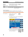
AFG-2225 Series User Manual
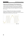
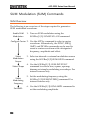
SUM modulation
Sum modulation adds a modulating signal to a carrier wave.
Typically, sum modulation is used to add noise to a carrier wave.
The modulating signal is added as a percentage of the carrier
amplitude.
If SUM is enabled, any other modulation mode will be disabled.
Likewise, burst and sweep modes cannot be used with SUM and
will be disabled when SUM is enabled.
100
APPENDIX
Selecting SUM modulation
For SUM modulation, the modulated waveform amplitude and
offset is determined by the carrier wave.
Panel Operation
1. Press the MOD key.
2. Press F5 (SUM).
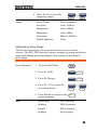
SUM Carrier Waveform
Background
Panel Operation
The SUM carrier waveform is a sinewave by
default.
1. Press the Waveform key.
2. Press F1~F5 to select the
carrier waveform.
Range
Carrier Waveform
n
~
os
Sine, square, pulse, ramp
and noise wave.
101
AFG-2225 Series User Manual
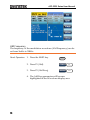
SUM Carrier Frequency
The maximum carrier frequency depends on the selected carrier
waveform. The default carrier frequency is 1kHz.
Panel Operation
1. Press the FREQ/Rate key to
select the carrier frequency.
/
2. The FREQ parameter will become highlighted
in the parameter window.
3. Use the arrow keys and scroll
wheel or number pad to enter
the frequency.
4. Press F1 ~ F5 to select the
frequency units.
Range
102
/
uz
~
Carrier Waveform
Carrier Frequency
Sine wave
1μHz~25MH
Square wave
1μHz~25MHz
Pulse wave
500μHz~25MHz
Ramp wave
1μHz~1MHz
Default frequency
1 kHz
z
APPENDIX
SUM Waveform
The function generator can accept internal and external sources. The
AFG-2225 includes sine, square, triangle, UpRamp and DnRamp as
internal sources. The default waveform is sine.
Panel Operation
1. Press the MOD key.
2. Press F5 (SUM).
hap
3. Press F4 (Shape).
4. Press F1~F5 to select the
source waveform.
5. Press Return to return to the
previous menu.
Range
n
~
namp
Return
Square wave
50% Duty cycle
Up ramp
100% Symmetry
Triangle
50% Symmetry
Down ramp
0% Symmetry
103
AFG-2225 Series User Manual
Modulating Waveform Frequency
The frequency of the modulating waveform (SUM Frequency) can be
set from 2mHz to 20kHz.
Panel Operation
1. Press the MOD key.
2. Press F5 (SUM).
rq
3. Press F3 (SUM Freq).
4. The SUM Freq parameter will become
highlighted in the waveform display area.
5. Use the arrow keys and scroll
wheel or number pad to enter
the SUM frequency.
6. Press F1~F3 to select the
frequency units.
Range
104
/
mz
Modulating range
2mHz~20kHz
Default frequency
100Hz
~
kz
APPENDIX
SUM Amplitude
The SUM amplitude is the offset (in percent relative to the carrier) of
the signal that is added to the carrier.
Panel Operation
1. Press the MOD key.
2. Press F5 (SUM).
mpl
3. Press F2 (SUM Ampl).
4. In the waveform display area, the SUM Ampl
will be highlighted.
5. Use the arrow keys and scroll
wheel or number pad to enter
the SUM amplitude.
6. Press F1 to select the
percentage unit.
Range
/
%
Sum amplitude
0~100%
Default amplitude
50%
105
AFG-2225 Series User Manual
Select the SUM Amplitude Source
The signal generator can accept internal or external sources for the
SUM amplitude modulation.
Panel Operation
1. Press the MOD key.
2. Press F5 (SUM).
our
3. Press F1 (Source).
4. Press F1 (INT) or F2 (EXT) to
select the source.
5. Press Return to return to the
previous menu.
External Source
Use the MOD INPUT terminal
on the rear panel when using an
external source.
~
Return
Trigger
MOD
Trigger
Counter
IN
OUT
Note
106
If an external modulation source is selected, the
SUM amplitude is controlled by the ± 5V from the
MOD INPUT terminal on the rear panel. For
example, if the SUM amplitude is set to 0%, then
the maximum amplitude (100% of the carrier ) will
be at +5V, and the minimum amplitude (0% of the
carrier) will be at -5V.
APPENDIX
107
AFG-2225 Series User Manual
Frequency Sweep
The function generator can perform a sweep for sine, square or ramp
waveforms, but not noise, and pulse. When Sweep mode is enabled,
Burst or any other modulation modes will be disabled. When sweep
is enabled, burst mode is automatically disabled.
In Sweep mode the function generator will sweep from a start
frequency to a stop frequency over a number of designated steps.
The step spacing of the sweep can linear or logarithmic. The
function generator can also sweep up or sweep down in frequency.
If manual or external sources are used, the function generator can be
used to output a single sweep.
108
APPENDIX
Selecting Sweep Mode
The Sweep button is used to output a sweep. If no
settings have been configured, the default settings
for output amplitude, offset and frequency are
used.
Setting Start and Stop Frequency
The start and stop frequencies define the upper and lower sweep
limits. The function generator will sweep from the start through to
the stop frequency and cycle back to the start frequency. The sweep
is phase continuous over the full range sweep range (1μHz-25MHz).
Panel Operation
1. Press the SWEEP key.
2. Press F3 (Start) or F4 (Stop) to
selelect the start or stop
frequency.
tart
~
top
3. The Start or Stop parameter will become
highlighted in the waveform display area.
Start
109
AFG-2225 Series User Manual
Stop
4. Use the arrow keys and scroll
wheel or number pad to enter
the Stop/Start frequency.
5. Press F1~F5 to select the
Start/Stop frequency units.
Range
Sweep Range
/
uz
~
z
1μHz~25MHz (Sine wave)
1μHz~1MHz (Ramp wave)
1μHz~15MHz (Square wave)
Start - Default
Note
100Hz
Stop - Default
1kHz
To sweep from low to high frequencies, set the
start frequency less than the stop frequency.
When marker is on, the SYNC signal is at a TTL
low level that rises to a TTL high level at the
marker.
To sweep from high to low frequencies, set the
start frequency greater than the stop frequency.
When marker is on, the SYNC signal is at a TTL
high level that drops to a TTL low level at the
marker.
When marker is off, the SYNC signal is turn off.
The frequency of the SYNC signal is equal to the
sweep time.
The SYNC signal is output from the trigger output
terminal.
110
APPENDIX
Center Frequency and Span
A center frequency and span can be set to determine the upper and
lower sweep limits (start/stop).
Panel Operation
1. Press the SWEEP key.
2. Press F5 (More).
or
3. Press F2 (Span) or F3 (Center)
to select the span or center.
pan
~
ntr
4. The Span or Center parameters will become
hightlighted in the waveform display area.
Span
Center
5. Use the arrow keys and scroll
wheel or number pad to enter
the Span/Center frequency.
6. Press F1~F5 to select the
Start/Stop frequency units.
/
uz
~
z
111
AFG-2225 Series User Manual
Range
Center frequency
1μHz~25MHz (sine wave)
1μHz~1MHz (Ramp wave)
1μHz~15MHz (square wave)
Span frequency
DC~+/-25MHz
(sine wave)
DC ~+/-1MHz (Ramp wave)
+/-1μHz~+/-15MHz (square
wave)
Note
Default center
550Hz
Default span
900Hz
To sweep from low to high frequencies, set a
positive span.
To sweep from high to low frequencies, set a
negative span.
112
APPENDIX
Sweep Mode
Sweep mode is used to select between linear or logarithmic
sweeping. Linear sweeping is the default setting.
Panel Operation
1. Press the SWEEP key.
2. Press F2 (Type).
3. To select linear or logarithmic
sweep, press F1 (Linear) or F2
(Log).
4. Press Return to return to the
previous menu.
yp
nar
~
o
Return
113
AFG-2225 Series User Manual
Sweep Time
The sweep time is used to determine how long it takes to perform a
sweep from the start to stop frequencies. The function generator
automatically determines the number of discrete frequencies used in
the scan depending on the length of the scan.
Panel Operation
1. Press the SWEEP key.
2. Press F5 (More).
3. Press F1 (SWP Time).
or
m
4. The Time parameter will become highlighted in
the waveform display area.
5. Use the selector keys and
scroll wheel or number pad
to enter the Sweep time.
114
/
APPENDIX
6. Press F1~F2 to select the time
unit.
Range
m
~
Sweep time
1ms ~ 500s
Default time
1s
Marker Frequency
The marker frequency is the frequency at which the marker signal goes low
/high(The marker signal is high/low at the start of each sweep). The marker
signal is output from the Trigger OUT terminal on the rear panel. The
default is 550 Hz.
Panel Operation
1. Press the SWEEP key.
2. Press F5 (More).
3. Press F4 (Marker)
4. Press F2 (ON/OFF) to toggle
the marker on or off.
5. Press F1 (Freq) to select the
marker frequency.
or
arkr
rq
6. The Marker parameter will become highlighted
in the waveform display area.
115
AFG-2225 Series User Manual
7. Use the arrow keys and scroll
wheel or number pad to enter
the frequency.
8. Press F1~F5 to select the
frequency unit.
Range
Frequency
/
uz
~
z
1μHz~25MHz(Sine wave)
1μHz~1MHz (Ramp wave)
1μHz~15MHz(square wave)
Default
Note
550Hz
The marker frequency must be set to a value
between the start and stop frequencies. If no value
is set, the marker frequency is set to the average of
the start and stop frequencies.
Marker mode will override SYNC mode settings
when sweep mode is active.
Sweep Trigger Source
In sweep mode the function generator will sweep each time a trigger
signal is received. After a sweep output has completed, the function
116
APPENDIX
generator outputs the start frequency and waits for a trigger signal
before completing the sweep. The default trigger source is internal.
Panel Operation
1. Press the SWEEP key.
2. Press F1 (Source).
our
3. To select the trigger source,
press F1 (Internal), F2
(External) or F3 (Manual).
4. Press Return to return to the
previous menu.
Note
~
anual
Return
Using the Internal source will produce a
continuous sweep using the sweep time settings.
With an external source, a sweep is output each
time a trigger pulse (TTL) is received from the
Trigger IN terminal on the rear panel.
The trigger period must be equal to or greater than
the sweep time plus 1ms.
5. If manual is selected, press F1
(Trigger) to manually start
each sweep.
rr
117
AFG-2225 Series User Manual
Burst Mode
The function generator can create a waveform burst with a
designated number of cycles. Burst mode supports sine, square ,ARB
and ramp waveforms.
118
APPENDIX
Selecting Burst Mode
When burst mode is selected, any modulation or
sweep modes will be automatically disabled. If no
settings have been configured, the default settings
for output amplitude, offset and frequency are
used.
Burst Modes
Burst mode can be configured using Triggered (N Cycle mode) or
Gated mode. Using N Cycle/Triggered mode, each time the function
generator receives a trigger, the function generator will output a
specified number of waveform cycles (burst). After the burst, the
function generator will wait for the next trigger before outputting
another burst. N Cycle is the default Burst mode. Triggered mode
can use internal or external triggers.
The alternative to using a specified number of cycles, Gated mode
uses the external trigger to turn on or off the output. When the
Trigger INPUT signal is high, waveforms are continuously output.
When the Trigger INPUT signal goes low, the waveforms will stop
being output after the last waveform completes its period. The
voltage level of the output will remain equal to the starting phase of
the burst waveforms, ready for the signal to go high again.
Burst Mode
Burst Count Burst Period Phase
Trigger
Source
Triggered (Int)
Available
Available
Available
Immediate
Triggered (Ext)
Available
Not used
Available
EXT, Bus
Gated pulse (Ext) Not used
Not used
Available
Unused
119
AFG-2225 Series User Manual
In Gated mode, burst count, burst cycle and trigger source are
ignored. If a trigger is input, then the trigger will be ignored and will
not generate any errors.
Panel Operation
1. Press the Burst key.
2. To select either N Cycle (F1)
or Gate (F2).
yl
~
at
Burst Frequency
In the N Cycle and Gated modes, the waveform frequency sets the
repetition rate of the burst waveforms. In N-Cycle mode, the burst is
output at the waveform frequency for the number of cycles set. In
Gated mode the waveform frequency is output while the trigger is
high. Burst mode supports sine, square ,ARB or ramp waveforms.
Panel Operation
1. Press the FREQ/Rate key.
/
2. The FREQ parameter will become highlighted
in the parameter window.
3. Use the arrow keys and scroll
wheel or number pad to enter
the frequency.
4. Press F1~F5 to select the
frequency unit.
120
/
uz
~
z
APPENDIX
Range
Note
Frequency_sine
1uHz~15MHz
Freqency – Ramp
1uHz~1MHz
Freqency – Square
1uHz~15MHz
Default
1kHz
Waveform frequency and burst period are not the
same. The burst period is the time between the
bursts in N-Cycle mode.
Burst Cycle/Burst Count
The burst cycle (burst count) is used to define the number of cycles
that are output for a burst waveform. Burst cycle is only used with
N-cycle mode (internal, external or manual source). The default
burst cycle is 1.
Panel Operation
1. Press the Burst key.
2. Press F1 (N Cycle).
yl
3. Press F1 (Cycles).
yls
4. The Cycles parameter will become highlighted
in the Waveform Display area.
121
AFG-2225 Series User Manual
5. Use the arrow keys and scroll
wheel or number pad to enter
the number of cycles.
6. Press F2 to select the Cyc
unit.
Range
Note
Cycles
/
y
1~65535
Burst cycles are continuously output when the
internal trigger is selected. The burst period
determines the rate of bursts and the time between
bursts.
Burst cycle must be less than the product of the
burst period and wave frequency.
Burst Cycle < (Burst Period x Wave Frequency)
If the burst cycle exceeds the above conditions, the
burst period will be automatically increased to
satisfy the above conditions.
If gated burst mode is selected, burst cycle is
ignored. Though, if the burst cycle is changed
remotely whilst in gated mode, the new burst cycle
is remembered when used next.
122
APPENDIX
Infinite Burst Count
Panel Operation
Note
1. Press the Burst key.
2. Press F1 (N Cycle).
yl
3. Press F2 (Infinite).
nfnt
Infinite burst is only available when using manual
triggering.
Burst Period
The burst period is used to determine the time between the start of
one burst and the start of the next burst. It is only used for internally
triggered bursts.
Panel Operation
1. Press the Burst key.
2. Press F1 (N Cycle).
yl
rod
3. Press F4 (Period).
123
AFG-2225 Series User Manual
4. The Period parameter will become highlighted
in the Waveform Display area.
5. Use the arrow keys and scroll
wheel or number pad to enter
period time.
6. Press F1~F3 to choose the
period time unit.
Range
Note
Period time
1ms~500s
Default
10ms
/
u
~
Burst period is only applicable for internal triggers.
Burst period settings are ignored when using gated
burst mode or for external and manual triggers.
The burst period must be large enough to satisfied the
condition below:
Burst Period>Burst Count/Wave frequency + 200ns.
124
APPENDIX
Burst Phase
Burst Phase defines the starting phase of the burst waveform. The
default is 0˚.
Panel Operation
1. Press the Burst key.
2. Press F1 (N Cycle).
yl
has
3. Press F3 (Phase).
4. The Phase parameter will become highlighted
in the Waveform Display area.
5. Use the arrow keys and scroll
wheel or number pad to enter
the phase.
6. Press F2 (Degreee) to select
the phase unit.
Range
r
/
Phase
-360˚~+360˚
Default
0˚
125
AFG-2225 Series User Manual
Note
When using sine, square, triangle or ramp
waveforms, 0˚ is the point where the waveforms
are at zero volts.
0˚ is the starting point of a waveform. For sine,
square or Triangle, Ramp waveforms, 0˚ is at 0
volts (assuming there is no DC offset).
Burst Phase is used for both N cycle and Gated
burst modes. In gated burst mode, when the
Trigger INPUT signal goes low the output is
stopped after the current waveform is finished.
The voltage output level will remain equal to the
voltage at the starting burst phase.
Burst Trigger Source
Each time the function generator receives a trigger in triggered burst
(N-Cycle) mode, a waveform burst is output. The number of
waveforms in each burst is designated by the burst cycle (burst
count). When a burst has completed, the function generator waits for
the next trigger. Internal source is the default triggered burst (Ncycle) mode on power up.
Panel Operation
1. Press the Burst key.
2. Press F1 (N Cycle).
yl
3. Press F5 (TRIG set).
st
4. Choose a trigger type by
pressing F1 (INT), F2 (EXT)
or F3 (Manual).
126
~
anual
APPENDIX
Manual
Triggering
If a manual source is selected, the
Trigger softkey (F1) must be
pressed each time to output a
burst.
Note
When the internal trigger source is chosen, the
burst is output continuously at a rate defined by
the burst period setting. The interval between
bursts is defined by the burst period.
rr
When the external trigger is selected the function
generator will receive a trigger signal (TTL) from
the Trigger INPUT terminal on the rear panel.
Each time the trigger is received, a burst is output
(with the defined number of cycles). If a trigger
signal is received during a burst, it is ignored.
When using the manual or external trigger only
the burst phase and burst cycle/count are
applicable, the burst period is not used.
A time delay can be inserted after each trigger,
before the start of a burst.
127
AFG-2225 Series User Manual
Burst Delay
Panel Operation
1. Press the Burst key.
2. Press F1 (N Cycle).
yl
3. Press F5 (TRIG set).
st
lay
4. Press F4 (Delay).
5. The Delay parameter will become highlighted
in the Waveform Display area.
6. Use the selector keys and
scroll wheel or number pad
to enter period time.
7. Press F1~F4 to choose the
delay time unit.
128
/
n
~
APPENDIX
Range
Delay time
0s~655350nS
Default
0s
Burst Trigger Output
The Trig Out terminal on the rear panel can be used for burst or
sweep modes to output a rising edge TTL compatible trigger signal.
By default the trigger signal is rising edge. The trigger signal is
output at the start of each burst.
Panel Operation
1. Press the Burst key.
2. Press F1 (N Cycle).
yl
3. Press F5 (TRIG set).
st
4. Press F5 (TRIG out).
out
5. Press F3 (ON/OFF) to toggle
Trigger out ON/OFF.
6. Select F1 (Rise) or F2 (Fall)
edge trigger.
Note
s
~
all
When the internal or external trigger is selected,
the trigger output signal will be at either a TTL
low/high level and will toggle.when the specifed
number of waveform cycles completed.
When the manual trigger is selected, the trigger
output turns on at the trigger soft-key be pressed.
129
AFG-2225 Series User Manual
130
APPENDIX
SECONDARY SYSTEM
FUNCTION SETTINGS
The secondary system functions are used to store and recall settings,
view help files, view the software version, update the firmware, set
the buzzer.
Save and Recall ............................................................... 132
System and Settings ........................................................ 136
System and Settings ........................................................ 136
Viewing and Updating the Firmware ................................. 136
Setting the Buzzer Sound .................................................. 137
131
AFG-2225 Series User Manual
Save and Recall
The AFG-2225 has non-volatile memory to store instrument state
and ARB data. There are 10 memory files numbered 0~9. Each
memory file can either store arbitrary waveform data (ARB), settings
or both. When data (ARB or Setting data) is stored in a memory file,
the data will be shown in red. If a file has no data, it will be shown in
blue.
Save/Recall
Properties
ARB
Rate
Display vertical
Frequency
Output Start
Length
Output length
Display horizontal
Setting
132
Functions
AM
Waveform
Source
Frequency
Shape
Pulse Width
Depth
Square wave Duty
AM frequency
Ramp Symmetry
Amplitude
Source
Amplitude unit
Shape
Offset
Deviation
Modulation type
FM frequency
Beep setting
Impedance
Source
Main output
Shape
Rate
Hop frequency
Sweep
Source
Type
Marker
FM
FSK
PM
Source
APPENDIX
Panel Operation
Time
Shape
Start frequency
Phase deviation
Stop frequency
Frequency
Center frequency
Span frequency
Source
Marker frequency
Trigger out
Type
Cycles
Phase
Period
Delay
Burst Type
1. Press the UTIL key.
2. Press F1 (Memory).
mory
3. Use the scroll wheel to
highlight a memory file
number.
133
AFG-2225 Series User Manual
4. Choose a file operation:
Press F1 to store a file, press
F2 to recall a file, or press F3
to delete a file.
tor
all
lt
on
5. Use the scroll wheel to
highlight the data type.
ARB, Setting or ARB+Setting
6. Press F5 (Done) to choose the
data type.
Range
Memory file
Memory0 ~ Memory9
Data type
ARB, Setting, ARB+Setting
7. Press F5 (Done) to confirm
the operation.
Delete All
134
8. To delete all the files for
Memory0~Memory9, press
F4.
on
ltll
APPENDIX
9. Press F1 (Done) to confirm
the deletion of all files.
on
135
AFG-2225 Series User Manual
System and Settings
There are a number of miscellaneous settings and firmware settings
that can be configured.
Viewing and Updating the Firmware
View Version
1. Press the UTIL key.
2. Press F2 (Cal.).
al
oftwar
rson
3. Press F2 (Software).
4. Press F1 (Version) to view the
firmware version.
The version information will be shown on screen:
Instrument, Version, FPGA Revision
Update Firmware 5. To update the firmware,
insert a USB flash drive with
a firmware file in the USB
host drive. Press F2
(Upgrade).
Note
136
prad
The firmware file (*.bin) must be located in a
directory, directly off the USB root directory.
APPENDIX
Setting the Buzzer Sound
Background
Turns the beeper on or off.
Panel Operation
1. Press the UTIL key.
2. Press F3 (System).
3. PressF3 (Beep) to toggle the
buzzer sound on or off.
4. Press F1(ON) or Press
F2(OFF)
ystm
p
~
Frequency Counter
Example: Turn on the frequency counter. Gate time: 1 second.
1. Press UTIL, F5 (Counter).
Output: N/A
Input:
Trigger
MOD
Trigger
Counter
IN
OUT
2. Press F1 (Gate Time), and
press F3 (1 Sec) to choose a
gate time of 1 second.
ountr
atm
3. Connect the signal of interest to the Frequency
counter input on the rear panel.
4. Input a 1kHz square wave signal into the
Counter input on the rear panel. Set the gate
time to 1S.
137
AFG-2225 Series User Manual
Frequency Coupling
Example: Frequency Coupling
1. Press UTIL, F4 (Dual Chan) to
enter the coupling function.
2. Press F1 (Freq Cpl) to select
the frequency coupling
function.
3. Press F2 (Offset). The offset is
the frequency difference
between CH1 and CH2. Use
the number keys or scroll
wheel to enter the offset.
There are two different
coupling modes. They are
calculated as follows:
Offset=CH2-CH1
Ratio=CH2/CH1
138
rqpl
ffst
ualhan
APPENDIX
4. Input an offset value of 1kHz.
Press F1~ F5 to select the
units.
uz
~
z
The frequency of channel 2 becomes 2kHz (CH2=CH1
+ Offset).
5. Change the frequency coupling mode to Ratio.
Set the ratio to 2.
The frequency of CH2 automatically changes
accordingly to match the ratio
(CH2=CH1*Ratio).
139
AFG-2225 Series User Manual
Amplitude Coupling
Example: Amplitude Coupling
1. The following assumes that the amplitude has
already been set to 4Vpp with a DC offset of
1Vdc.
2. Press UTIL, F4 (Dual
Chan) to enter the
coupling function.
3. Press F2 (Ampl Cpl),
F1 (ON) to select the
amplitude coupling
function.
ualhan
mplpl
n
4. The amplitude and offset between both channel
is coupled. Any changes in amplitude in the
current channel is reflected in the other
channel.
Tracking
Example: Tracking
140
APPENDIX
1. The method for outputting a square wave has
been previously described. Use this method to
output a 2kHz squarewave from CH1 with an
amplitude of 5Vpp and a DC offset of 1Vdc.
2. Press UTIL, F4 (Dual
Chan) to enter the
coupling function.
3. Press F3 (Tracking),
F2 (On) to turn on the
tracking function.
ualhan
rakn
n
4. When tracking is turned on, parameters such as
amplitude and frequency from the current
channel are mirrored on the other channel.
141
AFG-2225 Series User Manual
S_Phase
Example: S_phase
5. Press UTIL, Dual
Chan (F4) to enter the
coupling function.
ualhan
2. Press S_Phase (F4),
_has
turn on the S_Phase
function.
3. S_Phase function is to make the phase
synchronization between current channel and
another channel. Phase is 0°.here S_Phase
function is the same with S_Phase function under
CH1/CH2.
142
APPENDIX
CHANNEL SETTINGS
The channel settings chapter shows how to set the output
impedance, output phase and DSO connection settings.
Output Impedance ............................................................. 143
Selecting the Output Phase ............................................... 144
Synchronizing the Phase .................................................... 145
DSO Link ............................................................................ 146
Output Impedance
Background
The AFG-2225 has selectable output impedances:
50Ω or high impedance. The default output
impedance is 50Ω. The output impedances are to
be used as a reference only. If the actual load
impedance is different to that specified, then the
actual amplitude and offset will vary accordingly.
Panel Operation
1. Press the CH1/CH2 key.
Note
The load function can only be used if the ARB, MOD,
SWEEP or BURST functions are not active.
2. Press F1 (Load).
oad
143
AFG-2225 Series User Manual
3. Select F1 (50 OHM) or F2
(High Z) to select the output
impedance.
~
h
Selecting the Output Phase
Panel operation
1. Press the CH1/CH2 key.
Note
The phase function can only be used if the ARB,
MOD, SWEEP or BURST functions are not active.
Square and Pulse can not be change,phase is 0°
2. Press F4 (Phase) and then
press F1 (Phase)
has
has
3. The Phase parameter in the parameter window
will become hightlighed.
144
APPENDIX
4. Use the arrow keys and scroll
wheel or number pad to enter
the output phase.
5. Press F5 (Degree).
/
r
Synchronizing the Phase
Background
Synchronizes both the outputs on the AFG-2225.
Panel Operation
1. Press the CH1/CH2 key.
2. Press F4 (Phase).
3. Press F2 (S_Phase) to
synchronize the phase of the
channels.
has
_has
145
AFG-2225 Series User Manual
DSO Link
Background
DSO Link enables the AFG-2225 to receive lossless
data from a GDS-2000 Series DSO to create ARB
data.
1. Connect the AFG-2225 USB
host port to the GDS-2000’s
USB B device port.
Panel Operation
2. Press the CH1/CH2 key.
3. Press F5 (DSO Link).
4. Press F1 (Search).
5. To select a DSO channel,
Press F2 (CH1), F3 (CH2), F4
(CH3) or F5 (CH4). The
acquired data can then be
displayed.
146
→
CH1/CH2
nk
arh
~
APPENDIX
ARBITRARY WAVEFORMS
The AFG-2225 can create user-defined arbitrary waveforms with a
sample rate of 120MHz. Each waveform can include up to 4k of data
points with a vertical range of ±511.
Inserting Built-In Waveforms ........................................... 148
Create an AbsAtan Waveform ............................................ 148
Display an Arbitrary Waveform ........................................ 150
Set the Horizontal Display Range ...................................... 150
Set the Vertical Display Properties..................................... 152
Page Navigation (Back Page) ............................................. 154
Page Navigation (Next Page) ............................................. 156
Display ................................................................................ 158
Editing an Arbitrary Wavefrom ......................................... 159
Adding a Point to an Arbitrary Waveform .......................... 159
Adding a Line to an Arbitrary Waveform ........................... 160
Copy a Waveform ............................................................... 162
Clear the Waveform ............................................................ 164
ARB Protection ................................................................... 166
Ouput an Arbitrary Waveform .......................................... 169
Ouput Arbitrary Waveform................................................. 169
Saving/Loading an Arbitrary Waveform ............................ 171
Saving a Waveform to Internal Memory ............................ 171
Saving a Waveform to USB Memory ................................. 172
Load a Waveform from Internal Memory .......................... 175
Load a Waveform from USB .............................................. 178
147
AFG-2225 Series User Manual
Inserting Built-In Waveforms
The AFG-2225 includes 66 common waveforms, such as math
waveforms, windowing functions and engineering waveforms.
Create an AbsAtan Waveform
Panel Operation
1. Press the ARB key.
2. Press F3(Built in).
ultn
3. Press F4(Wave).
av
ommon
4. Press F1(Common).
5. Use the scroll wheel to select “AbsAtan” from
the built-in Common waveforms.
6. Press F5(Select) to select
AbsAtan waveform
7. Press F1(Start) and set the
start position of the AbsAtan
waveform.
8. You can also change the
length and scale of the
waveform by pressing
F2(Length) or F3(Scale).
9. Press F5 (Done) to complete
the operation
10. Press return to return to the
previous menu.
148
lt
tart
nth
al
on
Return
APPENDIX
Below an Absatan wave created at start:0, Length: 33,
Scale: 511
*Please see the appendix for other built-in waveforms
149
AFG-2225 Series User Manual
Display an Arbitrary Waveform
Set the Horizontal Display Range
The horizontal window bounds can be set in one of two ways: Using
a start point and length, or a center point and length.
Panel Operation
1. Press the ARB key.
2. Press F1 (Display) to enter the
display menu.
3. Press F1 (Horizon) to enter
the horizontal menu.
Using a Start
Point
splay
orzon
tart
4. Press F1( Start)
5. The H_From parameter will become
highlighted.
6. Use the arrow keys and scroll
wheel or number pad to enter
the H_From value.
7. Press Clear ( F1) to cancel.
8. Press F2 (Enter) to save the
settings.
9. Press Return to return to the
previous menu.
150
/
lar
ntr
Return
APPENDIX
Setting the
Length
10. Repeat steps 4~9 for Length
(F2).
Using a Center
Point
11. Repeat steps 4~9 for Center
(F3).
Zoom in
12. To zoom into the arbitrary
waveform, press F4 (Zoom
In). The Zoom In function
will reduce the length by half
each time the function is
used. The minimum
allowable length is 3.
Zoom out
13. To zoom out from the center
point of the waveform, press
F5 (Zoom out). The Zoom out
function will increase the
length by 2. The maximum
allowable length is 4096.
nth
ntr
oomn
oomout
Below, an arbitrary waveform has a start of 0,
length of 200 and is centered at 100.
151
AFG-2225 Series User Manual
Set the Vertical Display Properties
Like the horizontal properties, the vertical display properties of the
waveform display can be created in two ways: Setting high and low
values, or setting the center point.
Panel Operation
Setting the Low
Point
1. Press the ARB key.
2. Press F1 (Display).
splay
3. Press F2 (Vertical).
rtal
ow
4. Press F1 (Low).
5. The V_Low parameter will become highlighted.
6. Use the arrow keys and scroll
wheel or number pad to enter
the V_Low value.
7. Press Clear (F1) to cancel.
8. Press F2 (Enter) to save the
settings.
9. Press Return to return to the
previous menu.
Setting the High
Point
152
10. Repeat steps 4~9 for V_High
(F2).
/
lar
ntr
Return
h
APPENDIX
Setting the Center 11. Repeat steps 4~9 for Center
Point
(F3).
Zoom
12. To zoom in from the center of
the arbitrary waveform, press
F4 (Zoom in). The Zoom in
function will reduce the
length by half each time the
function is used. The
minimum allowable vertical
low is -2, and the minimum
vertical high is 2.
13. To zoom out of the
waveform, press F5 (Zoom
out). The Zoom out function
will increase the length by 2.
The Vertical low maximum
can be set to -511 and the
vertical high maximum can
be set to +511.
ntr
oomn
oomout
Below, the AbsAtan wave is with a vertical low of -511,
a vertical high 511 and a center of 0.
153
AFG-2225 Series User Manual
Page Navigation (Back Page)
Background
When viewing the waveform, the display window
can be moved forward and backward using the
Next/Back Page functions.
Panel Operation
1. Press the ARB key.
2. Press F1 (Display).
splay
aka
3. Press F4 (Back Page) to move
the display window one view
length backward.
H_From* = H_From - Length
Center*= Center – Length
*Length until 0
Below, shows the display after Back Page has been
pressed.
H_From: 200 0
Length: 200
Center:300 100
154
APPENDIX
155
AFG-2225 Series User Manual
Page Navigation (Next Page)
Background
When viewing the waveform, the display window
can be moved forward and backward using the
Next/Back Page functions.
Panel Operation
1. Press the ARB key.
2. Press F1 (Display).
splay
xta
3. Press F3 (Next Page) to move
the display window one view
length forward.
H_From*=H_From + Length
Center=Center + Length
*H_From +Length ≤ 4096
Below, shows the display after Next Page has been
pressed.
H_From: 0 200
Length: 200
Center:100 300
156
APPENDIX
157
AFG-2225 Series User Manual
Display
Panel Operation
1. Press the ARB key.
2. Press F1 (Display).
splay
vrvw
3. To make the display window
cover the whole waveform,
press F5 (Overview).
Horizontal: 0~4095
Vertical: 511~ -511
Below shows the display after Overview has been
selected.
H_From: 0 0
Length: 4004096
Center:200 2048
Vertical low/high: ±511
158
APPENDIX
Editing an Arbitrary Wavefrom
Adding a Point to an Arbitrary Waveform
Background
The AFG-2225 has a powerful editing function that
allows you to create points or lines anywhere on
the waveform.
Panel Operation
1. Press the ARB key.
2. Press F2 (Edit).
dt
3. Press F1 (Point).
ont
ddrss
4. Press F1 (Address).
5. The Address parameter becomes highlighted.
6. Use the arrow keys and scroll
wheel or number pad to enter
the Address value.
7. Press F2 (Enter) to save the
settings.
8. Press Return to return to the
previous menu.
9. Press F2 (Data).
/
ntr
Return
ata
159
AFG-2225 Series User Manual
10. The Data parameter will become highlighted.
11. Use the selector keys and
scroll wheel or number pad
to enter a Data value.
12. Press F2 (Enter) to save the
settings.
13. Press Return to return to the
previous menu.
14. Press return again to go back
to the ARB menu.
/
ntr
Return
Return
In the following figure the edited address is
shown in red.
Address 100,Data 200
Adding a Line to an Arbitrary Waveform
Background
160
The AFG-2225 has a powerful editing function that
allows you to create points or lines anywhere on
the waveform.
APPENDIX
Panel Operation
1. Press the ARB key.
2. Press F2 (Edit).
dt
3. Press F2 (Line).
n
tart
4. Press F1 (Start ADD).
5. The Start Address parameter will be
highlighted in red.
6. Use the arrowkeys keys and
scroll wheel or number pad
to enter the start address.
7. Press F2 (Enter) to save the
settings.
8. Press Return to return to the
previous menu.
/
ntr
Return
9. Repeat steps 4~8 for Start Data (F2), Stop
Address (F3) and Stop Data (F4).
10. Press F5 (Done) to confirm
the line edit.
11. Press Return to return to the
previous menu.
on
Return
161
AFG-2225 Series User Manual
The red line was created below with the following
properties:
Start Address: 0, Start Data: 0
Stop Address: 32, Stop Data: 0
Copy a Waveform
Panel Operation
1. Press the ARB key.
2. Press F2 (Edit).
dt
3. Press F3 (Copy).
opy
4. Press F1 (Start).
tart
5. The Copy From properties will become
highlighted in red.
162
APPENDIX
6. The the arrow keys and scroll
wheel or number pad to enter
the Copy From address.
7. Press F2 (Enter) to save the
settings.
8. Press Return to return to the
previous menu.
/
ntr
Return
9. Repeat steps 4~8 for Length (F2) and Paste To
(F3).
10. Press F5 (Done) to confirm
the selection.
11. Press Return to return to the
previous menu.
on
Return
A section of the waveform from points 0~33 was
copied to points 50~83:
Copy From: 0
Length: 33
To: 50
163
AFG-2225 Series User Manual
Clear the Waveform
Panel Operation
1. Press the ARB key.
2. Press F2 (Edit).
dt
3. Press F4 (Clear).
lar
4. Press F1 (Start).
tart
5. The Clear From properties will become
highlighted in red.
6. Use the arrow keys and scroll
wheel or number pad to enter
the Clear From address.
7. Press F2 (Enter) to save the
settings.
8. Press Return to return to the
previous menu.
9. Repeat steps 4~8 for Length
(F2).
10. Press F3 (Done) to clear the
selected section of the
arbitrary waveform.
164
/
ntr
Return
nth
on
APPENDIX
Delete All
11. Press F4 (ALL) to delete the
whole waveform.
12. Press F1 (Done) again to
confirm the deletion.
13. Press Return return to the
previous menu.
on
Return
Clear From: 20, Length: 33.
The same area after being cleared:
165
AFG-2225 Series User Manual
The result after the whole waveform is deleted:
ARB Protection
The protection function designates an area of the arbitrary
waveform that cannot be altered.
Panel Operation
1. Press the ARB key.
2. Press F2 (Edit).
dt
rott
tart
3. Press F5 (Protect).
4. Press F2 (Start).
5. The Protect Start properties will become
highlighted in red.
166
APPENDIX
6. Use the arrow keys and scroll
wheel or number pad to enter
the Protect Start address.
7. Press F2 (Enter) to save the
settings.
8. Press Return to return to the
previous menu.
9. Repeat steps 4~8 for Length
(F3).
10. Press F4 (Done) to confirm
the protected area.
Protect All
11. Press F1 (ALL) to protect the
whole waveform.
12. Press F1 (Done) to confirm.
Unprotect All
13. Press F5 (Unprotect) to
unprotect the whole
waveform.
14. Press F1 (Done) to confirm.
/
ntr
Return
nth
on
on
nprott
on
15. The waveform background will return back to
black. The property “Protect Off” be will
grayed out.
167
AFG-2225 Series User Manual
Below, the protected areas of the waveform are
shown with an orange background:
Start:0, Length: 100.
168
APPENDIX
Ouput an Arbitrary Waveform
The arbitrary waveform generator can output up to 4k points
(2~4096).
Ouput Arbitrary Waveform
Panel Operation
1. Press the ARB key.
2. Press F4 (Output).
3. Press F1 (Start).
utput
tart
4. The Start property will become highlighted in
red.
5. Use the arrow keys and scroll
wheel or number pad to enter
the Start address.
6. Press F2 (Enter) to confirm
the start point.
7. Press Return to return to the
previous menu.
8. Repeat steps 4~7 for Length
(F2).
9. Press Return to return to the
previous menu.
/
ntr
Return
nth
Return
169
AFG-2225 Series User Manual
The front panel terminal will output the following
waveform.
Start 0,Length 500
*ARB Marker Output
When turning on the ARB functionality,whether the ARB waveform is
being output or not,there is a pulse from the Trigger OUT port. The pulse
time is 1/RATE
170
APPENDIX
Saving/Loading an Arbitrary Waveform
The AFG-2225 can save and load arbitrary waveforms from 10
internal memory slots. Arbitrary waveforms can also be saved and
loaded from a USB memory stick.
Saving a Waveform to Internal Memory
Panel Operation
1. Press the ARB key.
2. Press F5 (More).
or
3. Press F1 (Save).
av
4. Press F1 (Start).
tart
5. The Start property will become highlighted in
red.
6. Use the arrow keys and scroll
wheel or number pad to enter
the Start address.
7. Press F2 (Enter) to confirm
the start point.
8. Press Return to return to the
previous menu.
9. Repeat steps 4~8 for Length
(F2).
10. Press F3 (Memory).
/
ntr
Return
nth
mory
171
AFG-2225 Series User Manual
11. Select a memory file using the
scroll wheel.
Memory0~Memory9
12. Press F1 (Select) to save the
selected memory file.
13. Press Return to return to the
previous menu.
lt
Return
Below the file Memory0 is selected using the scroll
wheel.
Saving a Waveform to USB Memory
Panel Operation
172
1. Press the ARB key.
2. Press F5 (More).
or
3. Press F1 (Save).
av
4. Press F1 (Start).
tart
APPENDIX
5. The Start propery will become highlighted in
red.
6. Use the arrow keys and scroll
wheel or number pad to enter
the Start address.
7. Press F2 (Enter) to confirm
the start point.
8. Press Return to return to the
previous menu.
9. Repeat steps 4~8 for Length
(F2).
10. Press F4 (USB).
/
ntr
Return
nth
lt
woldr
11. Use the scroll wheel to
navigate the file system.
12. Press Select to select
directories or files.
Create a Folder
1. Press F2 (New Folder).
2. The text editor will appear with a default folder
name of “NEW_FOL”.
173
AFG-2225 Series User Manual
New Folder:
NEW_FOL
A
B
C
D
E
F
G
H
I
J
K
L
M
N
O
P
Q
R
S
T
U
V
W
X
Y
Z
_
-
1
2
3
4
5
6
7
8
9
0
3. Use the scroll wheel to move
the cursor.
4. Use F1 (Enter Char) or F2
(Backspace) to create a folder
name.
ntrhar
~
akspa
5. Press F5 (Save) to save the
folder name.
Create a New File 1. Press F3 (New File).
av
wl
2. The text editor will appear with a default file
name of “NEW_FIL”.
New File(CSV):
NEW_FIL
174
A
B
C
D
E
F
G
H
I
J
K
L
M
N
O
P
Q
R
S
T
U
V
W
X
Y
Z
1
2
3
4
5
6
7
8
9
0
_
-
APPENDIX
3. Use the scroll wheel to move
the cursor.
4. Use F1 (Enter Char) or F2
(Backspace) to create a file
name.
5. Press F5 (Save) to save the file
name.
ntrhar
~
akspa
av
Below the folder, BIN, has been created in the root
directory.
Load a Waveform from Internal Memory
Panel Operation
1. Press the ARBkey.
2. Press F5 (More).
or
3. Press F2 (Load).
oad
mory
4. Press F1 (Memory).
175
AFG-2225 Series User Manual
5. Use the scroll whell to choose
a memory file.
6. Press Select to load the
selected memory file.
7. Press F3 (To) to choose the
starting point for the loaded
waveform.
lt
o
8. The Load To parameter will become
highlighted in red.
9. Use the selector keys and
scroll wheel or number pad
to enter the starting point.
10. Press F2(Enter) to confirm the
start point.
11. Press Return to return to the
previous menu.
12. Press F4(Done).
/
ntr
Return
on
Below the file Memory0 is selected using the scroll
wheel loaded to position 0.
176
APPENDIX
177
AFG-2225 Series User Manual
Load a Waveform from USB
Panel Operation
1. Press the ARB key.
2. Press F5 (More).
or
3. Press F2 (Load).
oad
4. Press F2 (USB).
lt
o
5. Use the scroll wheel to choose
a file name.
6. Press F1 (Select) to select the
file to load.
7. Press F3 (To) to choose the
starting point for the loaded
waveform.
8. The Load To property will become highlighted
in red.
9. Use the arrow keys and scroll
wheel or number pad to enter
the starting point.
10. Press F2(Enter) to confirm the
Start point.
11. Press F4(Done).
178
/
ntr
on
APPENDIX
Below the file AFG.CSV is selected using the scroll
wheel loaded to position 0.
179
AFG-2225 Series User Manual
REMOTE INTERFACE
Establishing a Remote Connection .................................. 181
Configure USB interface .................................................... 181
Remote control terminal connection................................. 182
Command Syntax ............................................................... 184
180
APPENDIX
Establishing a Remote Connection
The AFG-2225 supports USB remote connections.
Configure USB interface
USB
configuration
Panel Operation
PC side connector Type A, host
AFG-2225 side
connector
Type B, slave
Speed
1.1/2.0 (full speed)
1. Connect the USB cable to the
rear panel USB B (slave) port.
2. When the PC asks for the
USB driver, select
XXXXXXX.inf included in the
software package or
download the driver from the
GW website,
www.gwinstek.com.
181
AFG-2225 Series User Manual
Remote control terminal connection
Terminal
application
Invoke the terminal application such as MTTTY
(Multi-Threaded TTY). For USB, set the COM port,
baud rate, stop bit, data bit, and parity
accordingly.
To check the COM port No, see the Device
Manager in the PC. For WinXP, Control panel →
System → Hardware tab.
Functionality
check
Run this query command via the terminal.
*idn?
This should return the Manufacturer, Model
number, Serial number, and Firmware version in
the following format.
GW INSTEK, AFG-2225, SN:XXXXXXXX,Vm.mm
Note: ^j or ^m can be used as the terminal
character when using a terminal program.
PC Software
The proprietary PC software, downloadable from
GWInstek website, can be used for remote control.
Display
When a remote connection is established all panel
keys are locked bar F5.
1. Press REM/LOCK (F5) to
return the function generator
to local mode.
182
K
APPENDIX
183
AFG-2225 Series User Manual
Command Syntax
Compatible
standard
IEEE488.2, 1992 (fully compatible)
SCPI, 1994 (partially compatible)
Command Tree
The SCPI standard is an ASCII based standard that
defines the command syntax and structure for
programmable instruments.
Commands are based on a hierarchical tree
structure. Each command keyword is a node on
the command tree with the first keyword as the
root node. Each sub node is separated with a
colon.
Shown below is a section of the SOURce[1|2] root
node and the :PM and :PULSe sub nodes.
Root node
:SOURce[1|2]
2nd node
3rd node
Command types
184
:PULSe
:PM
SOURCE
Shape
:PERiod
:WIDTh
Commands can be separated in to three distinc
types, simple commands, compound commands
and queries.
Simple
A single command with/without
a parameter
Example
*OPC
Compound
Two or more commands
separated by a colon (:)
with/without a parameter
Example
SOURce1:PULSe:WIDTh
APPENDIX
Query
A query is a simple or compound
command followed by a question
mark (?). A parameter (data) is
returned. The maximum or
minimum value for a parameter
can also be queried where
applicable.
Example
SOURce1:FREQuency?
SOURce1:FREQuency? MIN
Command forms Commands and queries have two different forms,
long and short. The command syntax is written
with the short form of the command in capitals
and the remainder (long form) in lower case.
long
long
SOURce1:DCOffset
short
short
The commands can be written in capitals or lowercase, just so long as the short or long forms are
complete. An incomplete command will not be
recognized.
Below are examples of correctly written
commands:
LONG SOURce1:DCOffset
SOURCE1:DCOFFSET
source1:dcoffset
SHORT SOUR1:DCO
sour1:dco
185
AFG-2225 Series User Manual
Command
Format
SOURce1:DCOffset < offset>LF
1
2
3
4
1: command header
2: single space
3: parameter
4: message terminator
Square Brackets [] Commands that contain squares brackets indicate
that the contents are optional. The function of the
command is the same with or without the square
bracketed items. Brackets are not sent with the
command.
For example, the frequency query below can use any of
the following 3 forms:
SOURce1:FREQuency? [MINimum|MAXimum]
SOURce1:FREQuency? MAXimum
SOURce1:FREQuency? MINimum
SOURce1:FREQuency?
Braces {}
Commands that contain braces indicate one item
within the braces must be chosen. Braces are not
sent with the command.
Angled Brackets
<>
Angle brackets are used to indicate that a value
must be specified for the parameter. See the
parameter description below for details. Angled
brackets are not sent with the command.
Bars |
Bars are used to separate multiple parameter
choices in the command format.
Parameters
Type
Description
Example
<Boolean>
Boolean logic
0, 1/ON,OFF
<NR1>
integers
0, 1, 2, 3
<NR2>
decimal numbers 0.1, 3.14, 8.5
<NR3>
floating point
4.5e-1, 8.25e+1
<NRf>
any of NR1, 2, 3
1, 1.5, 4.5e-1
186
APPENDIX
<NRf+>
<Numeric>
NRf type with a
suffix including
MINimum,
MAXimum or
DEFault
parameters.
<aard>
Arbitrary ASCII
characters.
<discrete>
Discrete ASCII
character
parameters
NRf+ type
<peak deviation including
frequency unit
in Hz>
suffixes.
<rate in Hz>
<frequency>
1, 1.5, 4.5e-1
MAX, MIN,
IMM, EXT,
MAN
1 KHZ, 1.0 HZ,
ΜHZ
<amplitude>
NRf+ type
VPP
including voltage
peak to peak.
<offset>
NRf+ type
including volt
unit suffixes.
V
<seconds>
NRf+ type
including time
unit suffixes.
NS, S MS US
<percent>
NRf type
N/A
<depth in
percent>
Message
terminators
Note
LF CR
line feed code (new line) and
carriage return.
LF
line feed code (new line)
EOI
IEEE-488 EOI (End-Or-Identify)
^j or ^m should be used when using a terminal
program.
187
AFG-2225 Series User Manual
Command
Separators
Space
A space is used to separate a
parameter from a
keyword/command header.
Colon (:)
A colon is used to separate
keywords on each node.
Semicolon (;)
A semi colon is used to separate
subcommands that have the same
node level.
For example:
SOURce[1|2]:DCOffset?
SOURce[1|2]:OUTPut?
SOURce1:DCOffset?;OUTPut?
Colon +
Semicolon (:;)
A colon and semicolon can be
used to combine commands from
different node levels.
For example:
SOURce1:PM:SOURce?
SOURce:PULSe:WIDTh?
SOURce1:PM:SOURce?:;SOURce:
PULSe:WIDTh?
Comma (,)
When a command uses multiple
parameters, a comma is used to
separate the parameters.
For example:
SOURce:APPLy:SQUare 10KHZ, 2.0
VPP, -1V
188
APPENDIX
Command List
System Commands .......................................................... 193
SYSTem:ERRor? ................................................................. 193
*IDN? ................................................................................. 193
*RST ................................................................................... 194
SYSTem:VERSion?.............................................................. 194
*OPC .................................................................................. 194
*OPC? ................................................................................. 195
*WAI ................................................................................... 195
Status Register Commands ............................................. 196
*CLS.................................................................................... 196
*ESE .................................................................................... 196
*ESR? .................................................................................. 197
*STB? .................................................................................. 197
*SRE ................................................................................... 198
System Remote Commands ............................................. 199
SYSTem:LOCal ................................................................... 199
SYSTem:REMote ................................................................ 199
DISPlay ON/OFF............................................................... 199
Apply Commands ............................................................ 200
SOURce[1|2]:APPLy:SINusoid ............................................ 202
SOURce[1|2]:APPLy:SQUare .............................................. 202
SOURce[1|2]:APPLy:RAMP ................................................. 203
SOURce[1|2]:APPLy:PULSe ................................................ 203
SOURce[1|2]:APPLy:NOISe ................................................ 204
SOURce[1|2]:APPLy:USER .................................................. 204
SOURce[1|2]:APPLy? .......................................................... 205
Output Commands .......................................................... 206
SOURce[1|2]:FUNCtion ...................................................... 206
SOURce[1|2]:FREQuency ................................................... 207
SOURce[1|2]:AMPlitude ..................................................... 209
SOURce[1|2]:DCOffset ....................................................... 210
SOURce[1|2]:SQUare:DCYCle ............................................ 211
SOURce[1|2]:RAMP:SYMMetry .......................................... 212
OUTPut[1|2] ........................................................................ 213
OUTPut[1|2]:LOAD............................................................. 213
SOURce[1|2]:VOLTage:UNIT ............................................. 214
Pulse Configuration Commands ...................................... 216
SOURce[1|2]:PULSe:PERiod ............................................... 216
SOURce[1|2]:PULSe:WIDTh ............................................... 217
Amplitude Modulation (AM) Commands ......................... 218
AM Overview ...................................................................... 218
189
AFG-2225 Series User Manual
SOURce[1|2]:AM:STATe ..................................................... 219
SOURce[1|2]:AM:SOURce ................................................. 219
SOURce[1|2]:AM:INTernal:FUNCtion ............................... 220
SOURce[1|2]:AM:INTernal:FREQuency ............................. 221
SOURce[1|2]:AM:DEPTh .................................................... 221
Frequency Modulation (FM) Commands .......................... 223
FM Overview ...................................................................... 223
SOURce[1|2]:FM:STATe ..................................................... 224
SOURce[1|2]:FM:SOURce .................................................. 224
SOURce[1|2]:FM:INTernal:FUNCtion ............................... 225
SOURce[1|2]:FM:INTernal:FREQuency ............................. 226
SOURce[1|2]:FM:DEViation ............................................... 226
Frequency-Shift Keying (FSK) Commands ........................ 228
FSK Overview ..................................................................... 228
SOURce[1|2]:FSKey:STATe ................................................. 228
SOURce[1|2]:FSKey:SOURce ............................................. 229
SOURce[1|2]:FSKey:FREQuency ........................................ 229
SOURce[1|2]:FSKey:INTernal:RATE ................................... 230
Phase Modulation (PM)Commands ................................. 232
PM Overview ...................................................................... 232
SOURce[1|2]:PM:STATe ..................................................... 233
SOURce[1|2]:PM:SOURce.................................................. 233
SOURce[1|2]:PM:INTernal:FUNction ................................ 234
SOURce[1|2]:PM:INTernal:FREQuency ............................. 234
SOURce[1|2]:PM:DEViation ............................................... 235
SUM Modulation (SUM) Commands .............................. 236
SUM Overview ................................................................... 236
SOURce[1|2]:SUM:STATe .................................................. 237
SOURce[1|2]:SUM:SOURce ............................................... 237
SOURce[1|2]:SUM:INTernal:FUNction ............................. 238
SOURce[1|2]:SUM:INTernal:FREQuency .......................... 238
SOURce[1|2]:SUM:AMPL ................................................... 239
Frequency Sweep Commands ........................................... 240
Sweep Overview ................................................................. 240
SOURce[1|2]:SWEep:STATe ............................................... 241
SOURce[1|2]:FREQuency:STARt ........................................ 242
SOURce[1|2]:FREQuency:STOP......................................... 242
SOURce[1|2]:FREQuency:CENTer ..................................... 243
SOURce[1|2]:FREQuency:SPAN ........................................ 244
SOURce[1|2]:SWEep:SPACing ........................................... 245
SOURce[1|2]:SWEep:TIME................................................. 245
SOURce[1|2]:SWEep:SOURce ............................................ 246
SOURce[1|2]:MARKer:FREQuency..................................... 247
SOURce[1|2]:MARKer ........................................................ 247
190
APPENDIX
Burst Mode Commands ................................................... 249
Burst Mode Overview......................................................... 249
SOURce[1|2]:BURSt:STATe ................................................ 251
SOURce[1|2]:BURSt:MODE ............................................... 251
SOURce[1|2]:BURSt:NCYCles ............................................ 252
SOURce[1|2]:BURSt:INTernal:PERiod ............................... 253
SOURce[1|2]:BURSt:PHASe ............................................... 254
SOURce[1|2]:BURSt:TRIGger:SOURce .............................. 254
SOURce[1|2]:BURSt:TRIGger:DELay .................................. 255
SOURce[1|2]:BURSt:TRIGger:SLOPe ................................. 256
SOURce[1|2]:BURSt:TRIGger:MANual .............................. 257
SOURce[1|2]:BURSt:GATE:POLarity .................................. 257
SOURce[1|2]:BURSt:OUTPut:TRIGger:SLOPe .................. 258
OUTPut[1|2]:TRIGger ......................................................... 259
Arbitrary Waveform Commands ....................................... 260
Arbitrary Waveform Overview ............................................ 260
SOURce[1|2]:FUNCtion USER ........................................... 261
SOURce[1|2]:DATA:DAC .................................................... 261
SOURce[1|2]:ARB:EDIT:COPY ........................................... 262
SOURce[1|2]:ARB:EDIT:DELete ......................................... 263
SOURce[1|2]:ARB:EDIT:DELete:ALL .................................. 263
SOURce[1|2]:ARB:EDIT:POINt........................................... 263
SOURce[1|2]:ARB:EDIT:LINE ............................................. 264
SOURce[1|2]:ARB:EDIT:PROTect ....................................... 264
SOURce[1|2]:ARB:EDIT:PROTect:ALL ............................... 265
SOURce[1|2]:ARB:EDIT:UNProtect .................................... 265
SOURce[1|2]:ARB:OUTPut ................................................. 265
COUNTER ....................................................................... 266
COUNTER:STATE .............................................................. 266
COUNter:GATe .................................................................. 266
COUNter:VALue? ............................................................... 267
PHASE ............................................................................. 267
SOURce[1|2]:PHASe ........................................................... 267
SOURce[1|2]:PHASe:SYNChronize .................................... 268
SOURce[1|2]:PHASe:SYNChronize .................................... 268
SOURce1:PHASe:SYNChronize ......................................... 268
COUPLE .......................................................................... 268
SOURce[1|2]:FREQuency:COUPle:MODE ......................... 268
SOURce[1|2]:FREQuency:COUPle:OFFSet ........................ 269
SOURce[1|2]:FREQuency:COUPle:RATio .......................... 269
SOURce[1|2]:AMPlitude:COUPle:STATe ........................... 269
SOURce[1|2]:TRACk ........................................................... 270
Save and Recall Commands ............................................. 271
*SAV ................................................................................... 271
191
AFG-2225 Series User Manual
*RCL ................................................................................... 271
MEMory:STATe:DELete ..................................................... 271
MEMory:STATe:DELete ALL .............................................. 272
192
APPENDIX
System Commands
SYSTem:ERRor?
System Query
Description
Reads an error from the error queue. See page 286
for details regarding the error queue.
Query Syntax
SYSTem:ERRor?
Return parameter <string>
Example
Returns an error string,
<256 ASCII characters.
SYSTem:ERRor?
-138 Suffix not allowed
Returns an error string.
*IDN?
Description
System Query
Returns the function generator manufacturer,
model number, serial number and firmware
version number in the following format:
GW INSTEK,AFG-2225,SN:XXXXXXXX,Vm.mm
Query Syntax
*IDN?
Return parameter <string>
Example
*IDN?
GW INSTEK,AFG-2225,SN:XXXXXXXX,Vm.mm
Returns the identification of the function
generator.
193
AFG-2225 Series User Manual
*RST
System Command
Description
Reset the function generator to its factory default
state.
Note
Note the *RST command will not delete
instrument save states in memory.
Syntax
*RST
SYSTem:VERSion?
System Query
Description
Performs a system version query. Returns a string
with the instrument, firmware version, FPGA
revision
Query Syntax
SYSTem:VERSion?
Return parameter <string>
Example
SYST:VERS?
AFG-2225 VX.XXX_XXXX
Returns the year and version for that year (1).
*OPC
System Command
Description
This command sets the Operation Complete Bit
(bit 0) of the Standard Event Status Register after
the function generator has completed all pending
operations. For the AFG-2225, the *OPC command
is used to indicate when a sweep or burst has
completed.
Note
Before the OPC bit is set, other commands may be
executed.
Syntax
*OPC
194
APPENDIX
*OPC?
System Query
Description
Returns the OPC bit to the output buffer when all
pending operations have completed. I.e. when the
OPC bit is set.
Note
Commands cannot be executed until the *OPC?
query has completed.
Query Syntax
*OPC?
Return parameter 1
Example
*OPC?
1
Returns a “1” when all pending operations are
complete.
*WAI
System Command
Description
This command waits until all pending operations
have completed before executing additional
commands. I.e., when the OPC bit is set.
Note
This command is only used for triggered sweep
and burst modes.
Syntax
*WAI
195
AFG-2225 Series User Manual
Status Register Commands
*CLS
System Command
Description
The *CLS command clears all the event registers,
the error queue and cancels an *OPC command.
Syntax
*CLS
*ESE
System Command
Description
The Standard Event Status Enable command
determines which events in the Standard Event
Status Event register can set the Event Summary
Bit (ESB) of the Status Byte register. Any bit
positions set to 1 enable the corresponding event.
Any enabled events set bit 5 (ESB) of the Status
Byte register.
Note
The *CLS command clears the event register, but
not the enable register.
Syntax
Parameter
*ESE <enable value>
<enable value>
Example
*ESE 20
0~255
Sets a bit weight of 20 (bits 2 and 4).
Query Syntax
*ESE?
Return Parameter Bit
0
196
Register
Not used
Bit
4
Register
Message Available
1
Not used
5
Standard Event
2
Error Queue
6
Master Summary
3
Questionable
Data
7
Not used
APPENDIX
Example
*ESE?
4
Bit 2 is set.
*ESR?
System Command
Description
Reads and clears the Standard Event Status
Register. The bit weight of the standard event
status register is returned.
Note
The *CLS will also clear the standard event status
register.
Query Syntax
*ESR?
Return Parameter Bit
0
Query Example
Bit
4
Register
Execution Error
1
Register
Operation
Complete
Not Used
5
Command Error
2
Query Error
6
Not Used
3
Device Error
7
Power On
*ESR?
5
Returns the bit weight of the standard event status
register (bit 0 and 2).
*STB?
System Command
Description
Reads the Status byte condition register.
Note
Bit 6, the master summary bit, is not cleared.
Syntax
*STB?
197
AFG-2225 Series User Manual
*SRE
System Command
Description
The Service Request Enable Command determines
which events in the Status Byte Register are
allowed to set the MSS (Master summary bit). Any
bit that is set to “1” can cause the MSS bit to be set.
Note
The *CLS command clears the status byte event
register, but not the enable register.
Syntax
Parameter
*SRE <enable value>
<enable value>
Example
*SRE 12
0~255
Sets a bit weight of 12 (bits 2 and 3) for the service
request enable register.
Query Syntax
*SRE?
Return Parameter Bit
0
Query Example
Register
Not used
Bit
4
Register
Message Available
1
Not used
5
Standard Event
2
Error Queue
6
Master Summary
3
Questionable
Data
7
Not used
*SRE?
12
Returns the bit weight of the status byte enable
register.
198
APPENDIX
System Remote Commands
SYSTem:LOCal
System Command
Description
Sets the function generator to local mode. In local
mode, all front panel keys are operational.
Syntax
SYSTem:LOCal
Example
SYST:LOC
SYSTem:REMote
System Command
Description
Disables the front panel keys and puts the function
generator into remote mode
Syntax
SYSTem:REMote
Example
SYST:REM
DISPlay ON/OFF
Description
System Command
Enable or disable the front panel display of
function generator. When disabled, display does
not display any content.
Due to disabling the front panel display, the speed
of executing commands from the remote interface
will be improved.
Syntax
DISPlay ON/OFF
Example
DISPlay ON
199
AFG-2225 Series User Manual
Apply Commands
The APPLy command has 5 different types of outputs (Sine, Square,
Ramp, Pulse, Noise, ). The command is the quickest, easiest way to
output waveforms remotely. Frequency, amplitude and offset can be
specified for each function.
As only basic parameters can be set with the Apply command, other
parameters use the instrument default values.
The Apply command will set the trigger source to immediate and
disable burst, modulation and sweep modes. Turns on the output
commandOUTPut[1|2] ON. The termination setting will not be
changed.
As the frequency, amplitude and offset parameters are in nested
square brackets, amplitude can only be specified if the frequency has
been specified and offset can only be specified if amplitude has been
set. For the example:
SOURce[1|2]:APPLy:SINusoid [<frequency> [,<amplitude>
[,<offset>] ]]
Output Frequency For the output frequency, MINimum, MAXimum
and DEFault can be used. The default frequency
for all functions is set to 1 kHz. The maximum and
minimum frequency depends on the function
used. If a frequency output that is out of range is
specified, the max/min frequency will be used
instead. A “Data out range error will be
generated” from the remote terminal.
200
APPENDIX
Output
Amplitude
When setting the amplitude, MINimum,
MAXimum and DEFault can be used. The range
depends on the function being used and the output
termination (50Ω or high impedance). The default
amplitude for all functions is 100 mVpp (50Ω).
If the amplitude has been set and the output
termination is changed from 50Ω to high
impedance, the amplitude will double. Changing
the output termination from high impedance to
50Ω will half the amplitude.
Vrms, dBm or Vpp units can be used to specify the
output unit to use with the current command. The
VOLT:UNIT command can be used to set the units
when no unit is specified with the Apply
command. If the output termination is set to high
impedance, dBm units cannot be used. The units
will default to Vpp.
The output amplitude can be affected by the
function and unit chosen. Vpp and Vrms or dBm
values may have different maximum values due to
differences such as crest factor. For example, a
5Vrms square wave must be adjusted to 3.536
Vrms for a sine wave.
DC Offset voltage The offset parameter can be set to MINimum,
MAXimum or DEFault. The default offset is 0
volts. The offset is limited by the output amplitude
as shown below.
|Voffset| < Vmax – Vpp/2
If the output specified is out of range, the
maximum offset will be set.
201
AFG-2225 Series User Manual
The offset is also determined by the output
termination (50Ω or high impedance). If the offset
has been set and the output termination has
changed from 50Ω to high impedance, the offset
will double. Changing the output termination from
high impedance to 50Ω will half the offset.
SOURce[1|2]:APPLy:SINusoid
Description
Syntax
Parameter
Example
Source Specific
Command
Outputs a sine wave from the selected channel
when the command has executed. Frequency,
amplitude and offset can also be set.
SOURce[1|2]:APPLy:SINusoid [<frequency>
[,<amplitude> [,<offset>] ]]
<frequency>
1μHz~25MHz
<amplitude>
1mVpp~10Vpp (50Ω)
(3.536 Vrms)
<offset>
-4.99V~4.99V (50Ω)
SOUR1:APPL:SIN 2KHZ,MAX,MAX
Sets frequency to 2kHz and sets the amplitude and
offset to the maximum.
SOURce[1|2]:APPLy:SQUare
Description
Syntax
Parameter
Example
202
Source Specific
Command
Outputs a square wave from the selected channel
when the command has executed. Frequency,
amplitude and offset can also be set. The duty
cycle is set to 50%.
SOURce[1|2]:APPLy:SQUare [<frequency>
[,<amplitude> [,<offset>] ]]
<frequency>
1μHz~25MHz
<amplitude>
1mVpp~10Vpp (50Ω)
<offset>
-4.99V~4.99V (50Ω)
SOUR1:APPL:SQU 2KHZ,MAX,MAX
APPENDIX
Sets frequency to 2kHz and sets the amplitude and
offset to the maximum.
SOURce[1|2]:APPLy:RAMP
Source Specific
Command
Description
Outputs a ramp wave from the selected channel
when the command has executed. Frequency,
amplitude and offset can also be set. The
symmetry is set to 50%.
Syntax
SOURce[1|2]:APPLy:RAMP [<frequency>
[,<amplitude> [,<offset>] ]]
Parameter
<frequency>
1μHz~1MHz
<amplitude>
1mVpp~10Vpp (50Ω)
<offset>
-4.99V~4.99V (50Ω)
Example
SOUR1:APPL:RAMP 2KHZ,MAX,MAX
Sets frequency to 2kHz and sets the amplitude and
offset to the maximum.
SOURce[1|2]:APPLy:PULSe
Source Specific
Command
Description
Outputs a pulse waveform from the selected
channel when the command has executed.
Frequency, amplitude and offset can also be set.
Note
The PW settings from the SOURce[1|2]:PULS:
WIDT command are preserved. Edge and pulse
width may be adjusted to supported levels.
Repetition rates will be approximated from the
frequency. For accurate repetition rates, the period
should be adjusted using the
SOURce[1|2]:PULS:PER command
Syntax
SOUR[1|2]:APPLy:PULSe [<frequency> [,<amplitude>
[,<offset>] ]]
Parameter
<frequency>
500μHz~25MHz
<amplitude>
1mVpp~10Vpp (50Ω)
203
AFG-2225 Series User Manual
<offset>
Example
-4.99V~4.99V (50Ω)
SOUR1:APPL:PULS 1KHZ,MIN,MAX
Sets frequency to 1kHz and sets the amplitude to
minimum and the and offset to the maximum.
Source Specific
Command
SOURce[1|2]:APPLy:NOISe
Description
Outputs Gaussian noise. Amplitude and offset can
also be set.
Note
Frequency cannot be used with the noise function;
however a value (or DEFault) must be specified.
The frequency is remembered for the next function
used.
Syntax
SOURce[1|2]:APPLy:NOISe [<frequency|DEFault>
[,<amplitude> [,<offset>] ]]
Parameter
<frequency>
Not applicable
<amplitude>
1mVpp~10Vpp (50Ω)
<offset>
-4.99V~4.99V (50Ω)
Example
SOUR1:APPL:NOIS DEF, 3.0, 1.0
Sets the amplitude to 3 volts with an offset of 1
volt.
SOURce[1|2]:APPLy:USER
Source Specific
Command
Description
Outputs an arbitrary waveform from the selected
channel. The output is that specified from the
FUNC:USER command.
Note
Frequency and amplitude cannot be used with the
DC function; however a value (or DEFault) must
be specified. The values are remembered for the
next function used.
204
APPENDIX
Syntax
SOURce[1|2]:APPLy:USER [<frequency> [,<amplitude>
[,<offset>] ]]
Parameter
<frequency>
1μHz~60MHz
<amplitude>
1mVpp~10Vpp (50Ω)
<offset>
-4.99V~4.99V (50Ω)
Example
SOUR1:APPL:USER
SOURce[1|2]:APPLy?
Source Specific
Command
Description
Outputs a string with the current settings.
Note
The string can be passed back appended to the
Apply Command.
Syntax
SOURce[1|2]:APPLy?
Return Parameter <string>
Example
Function, frequency,
amplitude, offset
SOUR1:APPL?
SIN +5.0000000000000E+03,+3.0000E+00,-2.50E+00
Returns a string with the current function and
parameters, Sine, 5kHz, 3 Vpp, -2.5V offset.
205
AFG-2225 Series User Manual
Output Commands
Unlike the Apply commands, the Output commands are low level
commands to program the function generator.
This section describes the low-level commands used to program the
function generator. Although the APPLy command provides the
most straightforward method to program the function generator, the
low-level commands give you more flexibility to change individual
parameters.
SOURce[1|2]:FUNCtion
Source Specific
Command
Description
The FUNCtion command selects and outputs the
selected output. The User parameter outputs an
arbitrary waveform previously set by the
SOURce[1|2]:FUNC:USER command.
Note
If the function mode is changed and the current
frequency setting is not supported by the new
mode, the frequency setting will be altered to next
highest value.
Vpp and Vrms or dBm amplitude values may have
different maximum values due to differences such
as crest factor. For example, if a 5Vrms square
wave is changed to a sinewave, then the Vrms is
automatically adjusted to 3.536.
The modulation, burst and sweep modes can only
be used with some of the basic waveforms. If a
mode is not supported, the conflicting mode will
be disabled. See the table below.
206
APPENDIX
Sine
Square Ramp Pulse Noise ARB
AM
FM
PM
FSK
SWEEP
BURST
SUM
Syntax
SOURce[1|2]:FUNCtion {SINusoid|SQUare|RAMP|
PULSe|NOISe| USER}
Example
SOUR1:FUNC SIN
Sets the output as a sine function.
Query Syntax
SOURce[1|2]:FUNCtion?
Return Parameter SIN, SQU, RAMP, PULS,
NOIS, USER
Example
Returns the current output
type.
SOUR1:FUNC?
SIN
Current output is sine.
SOURce[1|2]:FREQuency
Source Specific
Command
Description
The SOURce[1|2]:FREQuency command sets the
output freuquency for the selected channel. The
query command returns the current frequency
setting.
Note
The maximum and minimum frequency depends
on the function mode.
Sine, Square
Ramp
1μHz~25MHz
Pulse
500μHz~25MHz
1μHz~1MHz
207
AFG-2225 Series User Manual
Noise
Not applicable
User
1μHz~60MHz
If the function mode is changed and the current
frequency setting is not supported by the new
mode, the frequency setting will be altered to next
highest value.
The duty cycle of square waveforms depends on the
frequency settings.
1.0% to 99.0%(frequency≤100 KHz)
10% to 90% (100 KHz ≤ frequency ≤1MHz)
50% (frequency ≤ 25 MHz)
If the frequency is changed and the set duty cycle
cannot support the new frequency, the highest
duty cycle available at that frequency will be used.
A “settings conflict” error will result from the
above scenario.
Syntax
SOURce[1|2]:FREQuency
{<frequency>|MINimum|MAXimum}
Example
SOUR1:FREQ MAX
Sets the frequency to the maximum for the current
mode.
Query Syntax
SOURce[1|2]:FREQuency?
Return Parameter <NR3>
Example
Returns the frequency for
the current mode.
SOUR1:FREQ? MAX
+1.0000000000000E+06
The maximum frequency that can be set for the
current function is 1MHz.
208
APPENDIX
SOURce[1|2]:AMPlitude
Source Specific
Command
Description
The SOURce[1|2]:AMPLitude command sets the
output amplitude for the selected channel. The
query command returns the current amplitude
settings.
Note
The maximum and minimum amplitude depends
on the output termination. The default amplitude
for all functions is 100 mVpp (50Ω). If the
amplitude has been set and the output termination
is changed from 50Ω to high impedance, the
amplitude will double. Changing the output
termination from high impedance to 50Ω will half
the amplitude.
The offset and amplitude are related by the
following equation.
|Voffset| < Vmax – Vpp/2
If the output termination is set to high impedance,
dBm units cannot be used. The units will default to
Vpp.
The output amplitude can be affected by the
function and unit chosen. Vpp and Vrms or dBm
values may have different maximum values due to
differences such as crest factor. For example, a
5Vrms square wave must be adjusted to 3.536
Vrms for a sine wave.
The amplitude units can be explicitly used each
time the SOURce[1|2]:AMPlitude command is
used. Alternatively, the VOLT:UNIT command can
be used to set the amplitude units for all
commands.
209
AFG-2225 Series User Manual
Syntax
SOURce[1|2]:AMPlitude {< amplitude>
|MINimum|MAXimum}
Example
SOUR1:AMP MAX
Sets the amplitude to the maximum for the current
mode.
Query Syntax
SOURce[1|2]:AMPlitude? {MINimum|MAXimum}
Return Parameter <NR3>
Example
Returns the amplitude for
the current mode.
SOUR1:AMP? MAX
+5.0000E+00
The maximum amplitude that can be set for the
current function is 5 volts.
SOURce[1|2]:DCOffset
Description
Note
Source Specific
Command
Sets or queries the DC offset for the current mode.
The offset parameter can be set to MINimum,
MAXimum or DEFault. The default offset is 0
volts. The offset is limited by the output amplitude
as shown below.
|Voffset| < Vmax – Vpp/2
If the output specified is out of range, the
maximum offset will be set.
The offset is also determined by the output
termination (50Ω or high impedance). If the offset
has been set and the output termination has
changed from 50Ω to high impedance, the offset
will double. Changing the output termination from
high impedance to 50Ω will half the offset.
210
APPENDIX
Syntax
SOURce[1|2]:DCOffset {< offset>
|MINimum|MAXimum}
Example
SOUR1:DCO MAX
Sets the offset to the maximum for the current
mode.
Query Syntax
SOURce[1|2]:DCOffset? {MINimum|MAXimum}
Return Parameter <NR3>
Example
Returns the offset for the
current mode.
SOUR1:DCO?
+3.0000E+00
The offset for the current mode is set to +3 volts.
SOURce[1|2]:SQUare:DCYCle
Source Specific
Command
Description
Sets or queries the duty cycle for square waves
only. The setting is remembered if the function
mode is changed. The default duty cycle is 50%.
Note
The duty cycle of square waveforms depend on the
frequency settings.
1.0% to 99.0%(frequency≤100 KHz)
10% to 90% (100 KHz ≤ frequency ≤1MHz)
50% (frequency ≤ 25 MHz)
If the frequency is changed and the set duty cycle
cannot support the new frequency, the highest
duty cycle available at that frequency will be used.
A “settings conflict” error will result from the
above scenario.
For square waveforms, the Apply command and
AM/FM modulation modes ignore the duty cycle
settings.
Syntax
SOURce[1|2]:SQUare:DCYCle {< percent>
|MINimum|MAXimum}
211
AFG-2225 Series User Manual
Example
SOUR1:SQU:DCYC MAX
Sets the duty cycle to the highest possible for the
current frequency.
Query Syntax
SOURce[1|2]:SQUare:DCYCle?
{MINimum|MAXimum}
Return Parameter <NR3>
Example
Returns the duty cycle as a
percentage.
SOUR1:SQU:DCYC?
+5.00E+01
The duty cycle is set 50%.
Source Specific
Command
SOURce[1|2]:RAMP:SYMMetry
Description
Sets or queries the symmetry for ramp waves only.
The setting is remembered if the function mode is
changed. The default symmetry is 50%.
Note
For ramp waveforms, the Apply command and
AM/FM modulation modes ignore the current
symmetry settings.
Syntax
SOURce[1|2]:RAMP:SYMMetry {< percent>
|MINimum|MAXimum}
Example
SOUR1:RAMP:SYMM MAX
Sets the symmetry to the 100%.
Query Syntax
SOURce[1|2]:RAMP:SYMMetry?
{MINimum|MAXimum}
Return Parameter <NR3>
Example
Returns the symmetry as a
percentage.
SOUR1:RAMP:SYMMetry?
+1.0000E+02
The symmetry is set as 100%.
212
APPENDIX
Source Specific
Command
OUTPut[1|2]
Description
Enables/Disables or queries the front panel output
from the selected channel. The default is set to off.
Note
If the output is overloaded by an external voltage,
the output will turn off and an error message will
be displayed. The overload must first be removed
before the output can be turned on again with
output command.
Using the Apply command automatically sets the
front panel output to on.
Syntax
OUTPut[1|2] {OFF|ON}
Example
OUTP1 ON
Turns the channel 1 output on.
Query Syntax
OUTPut[1|2]?
Return Parameter 1
ON
0
OFF
Example
OUTP1?
1
The channel 1 output is currently on.
OUTPut[1|2]:LOAD
Description
Source Specific
Command
Sets or queries the output termination. Two
impedance settings can be chosen, DEFault (50Ω)
and INFinity (high impedance >10 kΩ).
The output termination is to be used as a reference
only. If the output termination is set 50Ω but the
actual load impedance is not 50Ω, then the
amplitude and offset will not be correct.
Note
If the amplitude has been set and the output
termination is changed from 50Ω to high
impedance, the amplitude will double. Changing
213
AFG-2225 Series User Manual
the output termination from high impedance to
50Ω will half the amplitude.
If the output termination is set to high impedance,
dBm units cannot be used. The units will default to
Vpp.
Syntax
OUTPut[1|2]:LOAD {DEFault|INFinity}
Example
OUTP1:LOAD DEF
Sets the channel 1 output termination to 50Ω.
Query Syntax
OUTPut[1|2]:LOAD?
Return Parameter DEF
INF
Example
Default
INFinity
OUTP1:LOAD?
DEF
The output termination for channel 1 is set to 50Ω.
Source Specific
Command
SOURce[1|2]:VOLTage:UNIT
Description
Sets or queries the output amplitude units. There
are three types of units: VPP, VRMS and DBM.
Note
The units set with the VOLTage:UNIT command
will be used as the default unit for all amplitude
units unless a different unit is specifically used for
a command.
If the output termination is set to high impedance,
dBm units cannot be used. The Units will
automatically default to Vpp.
Syntax
SOURce[1|2]:VOLTage:UNIT {VPP|VRMS|DBM}
Example
SOUR1:VOLT:UNIT VPP
Sets the amplitude units to Vpp.
Query Syntax
SOURce[1|2]:VOLTage:UNIT?
Return Parameter VPP
VRMS
214
Vpp
Vrms
APPENDIX
DBM
Example
dBm
SOUR1:VOLT:UNIT?
VPP
The amplitude units are set to Vpp.
215
AFG-2225 Series User Manual
Pulse Configuration Commands
The pulse chapter is used to control and output pulse waveforms.
Unlike the APPLy command, low level control is possible including
setting the rise time, fall time, period and pulse width.
Period
90%
50%
90%
Pulse Width
50%
10%
10%
Rise time
Fall time
SOURce[1|2]:PULSe:PERiod
Source Specific
Command
Description
Sets or queries the pulse period. The default period
is 1 ms.
Note
The pulse period must be greater than the pulse
width and edge time(1.6x) combined.
Pulse Width + (1.6 * Edge Time) < Period
If the edge time or pulse width are too great, they
will automatically be reduced to fit the period by
the function generator.
The PULSe:PERiod function will change the period
for all functions, not just for the pulse waveforms.
If a different function is chosen and the current
period is out of range, the period will be
automatically adjusted to suit the new function.
Syntax
SOURce[1|2]:PULSe:PERiod
{<seconds>|MINimum|MAXimum}
Example
SOUR1:PULS:PER MIN
Sets the period to the minimum time allowed.
Query Syntax
SOURce[1|2]:PULSe:PERiod? [MINimum|MAXimum]
Return Parameter <seconds>
216
40ns~2000s
APPENDIX
Example
SOUR1:PULS:PER?
+1.0000E+01
The period is set to 10 seconds.
Source Specific
Command
SOURce[1|2]:PULSe:WIDTh
Description
Sets or queries the pulse width. The default pulse
width is 100us.
The minimum pulse width is affected by the
period time. If the period is over 20 or 200 seconds,
then the minimum pulse width is 1us and 10us,
respectively.
Pulse width is defined as the time from the rising
to falling edges (at a threshold of 50%).
Note
The pulse width cannot be less than the edge time
times 1.6.
Pulse Width > 1.6 * Edge Time
The pulse width must be less than the period
minus the edge time (x1.6).
Pulse Width < Period – (1.6 *Edge Time)
Syntax
SOURce[1|2]:PULSe:WIDTh
{<seconds>|MINimum|MAXimum}
Example
SOUR1:PULS:WIDT MAX
Sets the pulse width to the maximum allowed.
Query Syntax
SOURce[1|2]:PULSe:WIDTh? [MINimum|MAXimum]
Return Parameter <seconds>
Example
20 ns ~ 1999.9 seconds
SOUR1:PULS:WIDT? MIN
+8.0000E-09
The pulse width is set to 8 nanoseconds.
217
AFG-2225 Series User Manual
Amplitude Modulation (AM) Commands
AM Overview
To successfully create an AM waveform, the following commands
must be executed in order.
Enable AM
Modulation
2. Turn on AM modulation using the
SOURce[1|2]: AM:STAT ON command
Configure Carrier 3. Use the APPLy command to select a carrier
waveform. Alternatively the equivalent FUNC,
FREQ, AMPl, and DCOffs commands can be
used to create a carrier waveform with a
designated frequency, amplitude and offset.
Select
Modulation
Source
Select Shape
Set Modulating
Frequency
Set Modulation
Depth
218
4. Select an internal or external modulation source
using the SOURce[1|2]:AM:SOUR command.
5. Use the SOURce[1|2]:AM:INT:FUNC
command to select a sine, square, upramp,
dnramp or triangle modulating waveshape. For
internal sources only.
6. Set the modulating frequency using the
SOURce[1|2]: AM:INT:FREQ command. For
internal sources only.
7. Set the modulation depth using the
SOURce[1|2]: AM:DEPT command.
APPENDIX
SOURce[1|2]:AM:STATe
Source Specific
Command
Description
Sets or disables AM modulation. By default AM
modulation is disabled. AM modulation must be
enabled before setting other parameters.
Note
Burst or sweep mode will be disabled if AM
modulation is enabled. As only one modulation is
allowed at any one time, other modulation modes
will be disabled when AM modulation is enabled.
Syntax
SOURce[1|2]:AM:STATe {OFF|ON}
Example
SOUR1:AM:STAT ON
Enables AM modulation.
Query Syntax
SOURce[1|2]:AM:STATe?
Return Parameter 0
1
Example
Disabled (OFF)
Enabled (ON)
SOUR1:AM:STAT?
1
AM modulation mode is currently enabled.
SOURce[1|2]:AM:SOURce
Source Specific
Command
Description
Sets or queries the modulation source as internal
or external. Internal is the default modulation
source.
Note
If an external modulation source is selected,
modulation depth is limited to ± 5V from the MOD
INPUT terminal on the rear panel. For example, if
modulation depth is set to 100%, then the
maximum amplitude is +5V, and the minimum
amplitude is -5V.
Syntax
SOURce[1|2]:AM:SOURce {INTernal|EXTernal}
219
AFG-2225 Series User Manual
Example
SOUR1:AM:SOUR EXT
Sets the modulation source to external.
Query Syntax
SOURce[1|2]:AM:SOURce?
Return Parameter INT
Internal
EXT
External
Example
SOUR1:AM:SOUR?
INT
The modulation source is set to internal.
SOURce[1|2]:AM:INTernal:FUNCtion
Source Specific
Command
Description
Sets the shape of the modulating waveform from
sine, square, triangle, upramp and dnramp. The
default shape is sine.
Note
Square and triangle waveforms have a 50% duty
cycle. Upramp and dnramp have a symmetry of
100% and 0%, respectively.
Syntax
SOURce[1|2]:AM:INTernal:FUNCtion
{SINusoid|SQUare|TRIangle|UPRamp|DNRamp}
Example
SOUR1:AM:INT:FUNC SIN
Sets the AM modulating wave shape to sine.
Query Syntax
SOURce[1|2]:AM:INTernal:FUNCtion?
Return Parameter SIN
Example
Sine
UPRAMP
Upramp
SQU
Square
DNRAMP
Dnramp
TRI
Triangle
SOUR1:AM:INT:FUNC?
SIN
The shape for the modulating waveform is Sine.
220
APPENDIX
Source Specific
Command
SOURce[1|2]:AM:INTernal:FREQuency
Description
Sets the frequency of the internal modulating
waveform only. The default frequency is 100Hz.
Syntax
SOURce[1|2]:AM:INTernal:FREQuency
{<frequency>|MINimum|MAXimum}
Parameter
<frequency>
Example
SOUR1:AM:INT:FREQ +1.0000E+02
2 mHz~ 20 kHz
Sets the modulating frequency to 100Hz.
Query Syntax
SOURce[1|2]:AM:INTernal:FREQuency?
[MINimum|MAXimum]
Return Parameter <NR3>
Example
Returns the frequency in
Hz.
SOUR1:AM:INT:FREQ? MIN
+1.0000E+02
Returns the minimum frequency allowed.
SOURce[1|2]:AM:DEPTh
Source Specific
Command
Description
Sets or queries the modulation depth for internal
sources only. The default is 100%.
Note
The function generator will not output more than
±5V, regardless of the modulation depth.
The modulation depth of an external source is
controlled using the ±5V MOD INPUT terminal on
the rear panel, and not the
SOURce[1|2]:AM:DEPTh command.
Syntax
SOURce[1|2]:AM:DEPTh {<depth in percent>
|MINimum|MAXimum}
Parameter
<depth in percent>
Example
SOUR1:AM:DEPT 50
0~120%
Sets the modulation depth to 50%.
221
AFG-2225 Series User Manual
Query Syntax
SOURce[1|2]:AM:DEPTh? [MINimum|MAXimum]
Return Parameter <NR3>
Example
Return the modulation
depth as a percentage.
SOUR1:AM:DEPT?
+1.0000E+02
The modulation depth is 100%.
222
APPENDIX
Frequency Modulation (FM) Commands
FM Overview
The following is an overview of the steps required to generate an
FM waveform.
Enable FM
Modulation
1. Turn on FM modulation using the
SOURce[1|2]: FM:STAT ON command.
Configure Carrier 2. Use the APPLy command to select a carrier
waveform. Alternatively, the FUNC, FREQ,
AMPl, and DCOffs commands can be used to
create a carrier waveform with a designated
frequency, amplitude and offset.
Select
Modulation
Source
Select shape
Set Modulating
Frequency
Set Peak
Frequency
Deviation
3. Select an internal or external modulation source
using the SOURce[1|2]:FM:SOUR command.
4. Use the SOURce[1|2]:FM:INT:FUNC command
to select a sine, square, upramp, dnramp or
triangle modulating waveshape. For internal
sources only.
5. Set the modulating frequency using the
SOURce[1|2]: FM:INT:FREQ command. For
internal sources only.
6. Use the SOURce[1|2]:FM:DEV command to set
the frequency deviation.
223
AFG-2225 Series User Manual
Source Specific
Command
SOURce[1|2]:FM:STATe
Description
Sets or disables FM modulation. By default FM
modulation is disabled. FM modulation must be
enabled before setting other parameters.
Note
Burst or sweep mode will be disabled if FM
modulation is enabled. As only one modulation is
allowed at any one time, other modulation modes
will be disabled when FM modulation is enabled.
Syntax
SOUR[1|2]:FM:STATe {OFF|ON}
Example
SOUR1:FM:STAT ON
Enables FM modulation.
Query Syntax
SOURce[1|2]:FM:STATe?
Return Parameter 0
1
Example
Disabled (OFF)
Enabled (ON)
SOUR1:FM:STAT?
1
FM modulation mode is currently enabled.
SOURce[1|2]:FM:SOURce
Source Specific
Command
Description
Sets or queries the modulation source as internal
or external. Internal is the default modulation
source.
Note
If an external modulation source is selected,
modulation depth is limited to ± 5V from the MOD
INPUT terminal on the rear panel. For example, if
modulation depth is set to 100%, then the
maximum amplitude is +5V, and the minimum
amplitude is -5V.
Syntax
SOURce[1|2]:FM:SOURce {INTernal|EXTernal}
224
APPENDIX
Example
SOUR1:FM:SOUR EXT
Sets the modulation source to external.
Query Syntax
SOURce[1|2]:FM:SOURce?
Return Parameter INT
Internal
EXT
External
Example
SOUR1:FM:SOUR?
INT
The modulation source is set to internal.
SOURce[1|2]:FM:INTernal:FUNCtion
Source Specific
Command
Description
Sets the shape of the modulating waveform from
sine, square, triangle, upramp and dnramp. The
default shape is sine.
Note
Square and triangle waveforms have a 50% duty
cycle. Upramp and dnramp have a symmetry of
100% and 0%, respectively.
Syntax
SOURce[1|2]:FM:INTernal:FUNCtion
{SINusoid|SQUare|TRIangle|UPRamp|DNRamp}
Example
SOUR1:FM:INT:FUNC SIN
Sets the FM modulating wave shape to sine.
Query Syntax
SOURce[1|2]:FM:INTernal:FUNCtion?
Return Parameter SIN
Example
Sine
UPRAMP
Upramp
SQU
Square
DNRAMP
Dnramp
TRI
Triangle
SOUR1:FM:INT:FUNC?
SIN
The shape for the modulating waveform is Sine.
225
AFG-2225 Series User Manual
Source Specific
Command
SOURce[1|2]:FM:INTernal:FREQuency
Description
Sets the frequency of the internal modulating
waveform only. The default frequency is 10Hz.
Syntax
SOURce[1|2]:FM:INTernal:FREQuency
{<frequency>|MINimum|MAXimum}
Parameter
<frequency>
Example
SOUR1:FM:INT:FREQ 100
2 mHz~ 20 kHz
Sets the modulating frequency to 100Hz.
Query Syntax
SOURce[1|2]:FM:INTernal:FREQuency?
[MINimum|MAXimum]
Return Parameter <NR3>
Example
Returns the frequency in
Hz.
SOUR1:FM:INT:FREQ? MAX
+2.0000E+04
Returns the maximum frequency allowed.
SOURce[1|2]:FM:DEViation
Description
Source Specific
Command
Sets or queries the peak frequency deviation of the
modulating waveform from the carrier waveform.
The default peak deviation is 100Hz.
The frequency deviation of external sources is
controlled using the ±5V MOD INPUT terminal on
the rear panel. A positive signal (>0~+5V) will
increase the deviation (up to the set frequency
deviation), whilst a negative voltage will reduce
the deviation.
Note
The relationship of peak deviation to modulating
frequency and carrier frequency is shown below.
Peak deviation = modulating frequency – carrier
frequency.
The carrier frequency must be greater than or
226
APPENDIX
equal to the peak deviation frequency. The sum of
the deviation and carrier frequency must not
exceed the maximum frequency for a specific
carrier shape. If an out of range deviation is set for
any of the above conditions, the deviation will be
automatically adjusted to the maximum value
allowed and an “out of range” error will be
generated.
For square wave carrier waveforms, the deviation
may cause the duty cycle frequency boundary to
be exceeded. In these conditions the duty cycle will
be adjusted to the maximum allowed and a
“settings conflict” error will be generated.
Syntax
SOURce[1|2]:FM:DEViation {<peak deviation in
Hz>|MINimum|MAXimum}
Parameter
<peak deviation in Hz>
DC~25MHz
DC~15MHz(square)
DC~1MHz (Ramp)
Example
SOUR1:FM:DEV MAX
Sets the frequency deviation to the maximum
value allowed.
Query Syntax
SOURce[1|2]:FM:DEViation? [MINimum|MAXimum]
Return Parameter <NR3>
Example
Returns the frequency
deviation in Hz.
SOURce[1|2]:FM:DEViation? MAX
+1.0000E+01
Returns the maximum frequency deviation
allowed.
227
AFG-2225 Series User Manual
Frequency-Shift Keying (FSK) Commands
FSK Overview
The following is an overview of the steps required to generate an
FSK modulated waveform.
Enable FSK
Modulation
1. Turn on FSK modulation using the
SOURce[1|2]: FSK:STAT ON command.
Configure Carrier 2. Use the APPLy command to select a carrier
waveform. Alternatively, the FUNC, FREQ,
AMPl, and DCOffs commands can be used to
create a carrier waveform with a designated
frequency, amplitude and offset.
Select FSK Source 3. Select an internal or external modulation source
using the SOURce[1|2]:FSK:SOUR command.
Select FSK HOP
Frequency
Set FSK Rate
4. Set the hop frequency using the
SOURce[1|2]:FSK:FREQ command.
5. Use the SOURce[1|2]: FSK:INT:RATE
command to set the FSK rate. The FSK rate can
only be set for internal sources.
SOURce[1|2]:FSKey:STATe
Source Specific
Command
Description
Turns FSK Modulation on or off. By default FSK
modulation is off.
Note
Burst or sweep mode will be disabled if FSK
modulation is enabled. As only one modulation is
allowed at any one time, other modulation modes
will be disabled when FSK modulation is enabled.
Syntax
SOURce[1|2]:FSKey:STATe {OFF|ON}
Example
SOUR1:FSK:STAT ON
228
APPENDIX
Enables FSK modulation
Query Syntax
SOURce[1|2]:FSKey:STATe?
Return Parameter 0
1
Example
Disabled (OFF)
Enabled (ON)
SOUR1:FSK:STAT?
1
FSK modulation is currently enabled.
Source Specific
Command
SOURce[1|2]:FSKey:SOURce
Description
Sets or queries the FSK source as internal or
external. Internal is the default source.
Note
If an external FSK source is selected, FSK rate is
controlled by the Trigger INPUT terminal on the
rear panel.
Syntax
SOURce[1|2]:FSKey:SOURce {INTernal|EXTernal}
Example
SOUR1:FSK:SOUR EXT
Sets the FSK source to external.
Query Syntax
SOURce[1|2]:FSKey:SOURce?
Return Parameter INT
Internal
EXT
External
Example
SOUR1:FSK:SOUR?
INT
The FSK source is set to internal.
SOURce[1|2]:FSKey:FREQuency
Source Specific
Command
Description
Sets the FSK hop frequency. The default hop
frequency is set to 100Hz.
Note
For FSK, the modulating waveform is a square
wave with a duty cycle of 50%.
229
AFG-2225 Series User Manual
Syntax
SOURce[1|2]:FSKey:FREQuency
{<frequency>|MINimum|MAXimum}
Parameter
<frequency>
1 μHz~25MHz(sine)
1 μHz~15MHz(Square、
Pulse)
1 μHz~1MHz(Ramp)
Example
SOUR1:FSK:FREQ +1.0000E+02
Sets the FSK hop frequency to to 100Hz.
Query Syntax
SOURce[1|2]:FSKey:FREQuency?
[MINimum|MAXimum]
Return Parameter <NR3>
Example
Returns the frequency in
Hz.
SOUR1:FSK:FREQ? MAX
+2.5000E+06
Returns the maximum hop frequency allowed.
Source Specific
Command
SOURce[1|2]:FSKey:INTernal:RATE
Description
Sets or queries the FSK rate for internal sources
only.
Note
External sources will ignore this command.
Syntax
SOURce[1|2]:FSKey:INTernal:RATE {<rate in Hz>
|MINimum|MAXimum}
Parameter
<rate in Hz>
Example
SOUR1:FSK:INT:RATE MAX
2 mHz~100 kHz
Sets the rate to the maximum (100kHz).
Query Syntax
SOURce[1|2]:FSKey:INTernal:RATE?
[MINimum|MAXimum]
Return Parameter <NR3>
230
Returns the FSK rate in
Hz.
APPENDIX
Example
SOUR1:FSK:INT:RATE? MAX
+1.0000E+05
Returns the maximum FSK rate allowed.
231
AFG-2225 Series User Manual
Phase Modulation (PM)Commands
PM Overview
The following is an overview of the steps required to generate a PM
modulated waveform.
Enable PM
Modulation
1. Turn on PM modulation using the
SOURce[1|2]: PM:STATe ON command.
Configure Carrier 2. Use the APPLy command to select a carrier
waveform. Alternatively, the FUNC, FREQ,
AMPl, and DCOffs commands can be used to
create a carrier waveform with a designated
frequency, amplitude and offset.
Select
Modulation
Source
Select Shape
Select
Modulating
Frequency
Set DEViation
232
3. Select an internal or external modulation source
using the SOURce[1|2]:PM:SOUR command.
4. Use the SOURce[1|2]: PM:INT:FUNC
command to select a sine, square, upramp,
dnramp or triangle modulating waveshape. For
internal sources only.
5. Set the modulating frequency using the
SOURce[1|2]:PM:INT:FREQ command. For
internal sources only.
6. Use the SOURce[1|2]:PM:DEV command to set
the phase DEViation.
APPENDIX
Source Specific
Command
SOURce[1|2]:PM:STATe
Description
Turns PM Modulation on or off. By default PM
modulation is off.
Note
Burst or sweep mode will be disabled if PM
modulation is enabled. As only one modulation is
allowed at any one time, other modulation modes
will be disabled when PM modulation is enabled.
Syntax
SOURce[1|2]:PM:STATe {OFF|ON}
Example
SOUR1:PM:STAT ON
Enables PM modulation
Query Syntax
SOURce[1|2]:PM:STATe?
Return Parameter 0
1
Example
Disabled (OFF)
Enabled (ON)
SOUR1:PM:STAT?
1
PM modulation is currently enabled.
Source Specific
Command
SOURce[1|2]:PM:SOURce
Description
Sets or queries the PM source as internal or
external. Internal is the default source.
Note
If an external PM source is selected, the phase
modulation is controlled by the MOD INPUT
terminal on the rear panel.
Syntax
SOURce[1|2]:PM:SOURce {INTernal|EXTernal}
Example
SOUR1:PM:SOUR EXT
Sets the PM source to external.
Query Syntax
SOURce[1|2]:PM:SOURce?
Return Parameter INT
Internal
EXT
External
233
AFG-2225 Series User Manual
Example
SOUR1:PM:SOUR?
INT
The PM source is set to internal.
SOURce[1|2]:PM:INTernal:FUNction
Source Specific
Command
Description
Sets the shape of the modulating waveform from
sine, square, triangle, upramp and dnramp. The
default shape is sine.
Note
Square and triangle waveforms have a 50% duty
cycle. Upramp and dnramp have a symmetry to
100% and 0%, respectively. .
Syntax
SOURce[1|2]:PM:INTernal:FUNction
{SINusoid|SQUare|TRIangle|UPRamp|DNRamp}
Example
SOUR1:PM:INT:FUN SIN
Sets the PM modulating wave shape to sine. .
Query Syntax
SOURce[1|2]:PM:INTernal:FUNction?
Return Parameter SIN
Example
Sine
UPRAMP
Upramp
SQU
Square
DNRAMP
Dnramp
TRI
Triangle
SOUR1:PM:INT:FUNC?
SIN
The shape for the modulating waveform is Sine.
SOURce[1|2]:PM:INTernal:FREQuency
Source Specific
Command
Description
Sets the modulating waveform frequency for
internal sources. The default frequency is set to
100Hz.
Syntax
SOURce[1|2]:PM:INTernal:FREQuency
{<frequency>|MINimum|MAXimum}
Parameter
<frequency>
234
2 mHz~ 20 kHz
APPENDIX
Example
SOUR1:PM:INT:FREQ MAX
Sets the frequency to the maximum value.
Query Syntax
SOURce[1|2]:PM:INTernal:FREQuency?
Return Parameter <NR3>
Example
Returns the frequency in
Hz.
SOUR1:PM:INT:FREQ? MAX
+2.0000E+04
Returns the modulating frequency. (20kHz)
Source Specific
Command
SOURce[1|2]:PM:DEViation
Description
Sets or queries the phase deviation of the
modulating waveform from the carrier waveform.
The default phase deviation is 180°.
Note
For external sources, the phase deviation is
controlled by the ±5V MOD Input terminal on the
rear panel. If the phase deviation is set to 180
degrees, then +5V represents a deviation of 180
degrees. A lower input voltage will decrease the
set phase deviation.
Syntax
SOURce[1|2]:PM:DEViation {< phase>|minimum
|maximum}
Parameter
<percent>
Example
SOUR1:PM:DEViation +3.0000E+01
0°~360°
Sets the deviation to 30°.
Query Syntax
SOURce[1|2]:PM:DEViation?
Return Parameter <NR3>
Example
Returns the deviation .
SOUR1:PM:DEViation?
+3.0000E+01
The current deviation is 30°.
235
AFG-2225 Series User Manual
SUM Modulation (SUM) Commands
SUM Overview
The following is an overview of the steps required to generate a
SUM modulated waveform.
Enable SUM
Modulation
1. Turn on SUM modulation using the
SOURce[1|2]: SUM:STATe ON command.
Configure Carrier 2. Use the APPLy command to select a carrier
waveform. Alternatively, the FUNC, FREQ,
AMPl, and DCOffs commands can be used to
create a carrier waveform with a designated
frequency, amplitude and offset.
Select
Modulation
Source
Select Shape
Select
Modulating
Frequency
Set AMPL
236
3. Select an internal or external modulation source
using the SOURce[1|2]:SUM:SOUR command.
4. Use the SOURce[1|2]: SUM:INT:FUNC
command to select a sine, square, upramp,
dnramp or triangle modulating waveshape. For
internal sources only.
5. Set the modulating frequency using the
SOURce[1|2]:SUM:INT:FREQ command. For
internal sources only.
6. Use the SOURce[1|2]:SUM:AMPL command to
set the modulating amplitude.
APPENDIX
Source Specific
Command
SOURce[1|2]:SUM:STATe
Description
Turns SUM Modulation on or off. By default SUM
modulation is off.
Note
Burst or sweep mode will be disabled if SUM
modulation is enabled. As only one modulation is
allowed at any one time, other modulation modes
will be disabled when SUM modulation is
enabled.
Syntax
SOURce[1|2]:SUM:STATe {OFF|ON}
Example
SOUR1:SUM:STAT ON
Enables SUM modulation
Query Syntax
SOURce[1|2]:SUM:STATe?
Return Parameter 0
1
Example
Disabled (OFF)
Enabled (ON)
SOUR1:SUM:STAT?
ON
SUM modulation is currently enabled.
Source Specific
Command
SOURce[1|2]:SUM:SOURce
Description
Sets or queries the SUM source as internal or
external. Internal is the default source.
Note
If an external SUM source is selected, the
amplitude is controlled by the MOD INPUT
terminal on the rear panel.
Syntax
SOURce[1|2]:SUM:SOURce {INTernal|EXTernal}
Example
SOUR1:SUM:SOUR EXT
Sets the SUM source to external.
Query Syntax
SOURce[1|2]:SUM:SOURce?
Return Parameter INT
Internal
237
AFG-2225 Series User Manual
EXT
Example
External
SOUR1:SUM:SOUR?
INT
The SUM source is set to internal.
Source Specific
Command
SOURce[1|2]:SUM:INTernal:FUNction
Description
Sets the shape of the modulating waveform from
sine, square, triangle, upramp and dnramp. The
default shape is sine.
Note
Square and triangle waveforms have a 50% duty
cycle. Upramp and dnramp have a symmetry to
100% and 0%, respectively. .
Syntax
SOURce[1|2]:SUM:INTernal:FUNction
{SINusoid|SQUare|TRIangle|UPRamp|DNRamp}
Example
SOUR1:SUM:INT:FUN SIN
Sets the SUM modulating wave shape to sine.
Query Syntax
SOURce[1|2]:SUM:INTernal:FUNction?
Return Parameter SIN
Example
Sine
UPRAMP
Upramp
SQU
Square
DNRAMP
Dnramp
TRI
Triangle
SOUR1:SUM:INT:FUNC?
SIN
The shape for the modulating waveform is Sine.
SOURce[1|2]:SUM:INTernal:FREQuency
Source Specific
Command
Description
Sets the modulating waveform frequency for
internal sources. The default frequency is set to
100Hz.
Syntax
SOURce[1|2]:SUM:INTernal:FREQuency
{<frequency>|MINimum|MAXimum}
238
APPENDIX
Parameter
<frequency>
2 mHz~ 20 kHz
Example
SOUR1:SUM:INT:FREQ MAX
Sets the frequency to the maximum value.
Query Syntax
SOURce[1|2]:SUM:INTernal:FREQuency?
Return Parameter <NR3>
Example
Returns the frequency in
Hz.
SOUR1:SUM:INT:FREQ? MAX
+2.0000E+04
Returns the modulating frequency (20kHz).
Source Specific
Command
SOURce[1|2]:SUM:AMPL
Description
Sets or queries the amplitude of the modulating
waveform from the carrier waveform. The default
phase amplitude is 50%.
Note
If an external SUM source is selected, the
amplitude of the modulated waveform is
controlled using the ±5V MOD INPUT terminal on
the rear panel. A positive signal (>0~+5V) will
increase the AMPLitude (up to the set amplitude),
whilst a negative voltage will reduce the
amplitude.
Syntax
SOURce[1|2]:SUM:AMPL{< percent>|minimum
|maximum}
Parameter
<percent>
Example
SOUR1:SUM:AMPLitude +3.0000E+01
0%~100%
Sets the amplitude to 30%.
Query Syntax
SOURce[1|2]:SUM:AMPLitude?
Return Parameter <NR3>
Example
Returns the amplitude .
SOUR1:SUM:AMPLitude?
+3.0000E+01
The current amplitude is 30%.
239
AFG-2225 Series User Manual
Frequency Sweep Commands
Sweep Overview
Below shows the order in which commands must be executed to
perform a sweep.
Enable Sweep
Mode
1. Turn on Sweep mode modulation using the
SOURce[1|2]: SWE:STAT ON command.
Select waveform
shape, amplitude
and offset
2. Use the APPLy command to select the
waveform shape. Alternatively, the FUNC,
FREQ, AMPl, and DCOffs commands can be
used to create a waveform with a designated
frequency, amplitude and offset.
Select Sweep
Boundaries
3. Set the frequency boundaries by setting start
and stop frequencies or by setting a center
frequency with a span.
Start~Stop Use the SOURce[1|2]:FREQ:STAR
and SOURce[1|2]:FREQ:STOP to
set the start and stop frequencies.
To sweep up or down, set the stop
frequency higher or lower than the
start frequency.
Span
Select Sweep
Mode
240
Use the SOURce[1|2]:FREQ:CENT
and SOURce[1|2]:FREQ:SPAN
commands to set the center
frequency and the frequency span.
To sweep up or down, set the span
as positive or negative.
4. Choose Linear or Logarithmic spacing using
the SOURce[1|2]:SWE:SPAC command.
APPENDIX
5. Choose the sweep time using the
SOURce[1|2]:SWE:TIME command.
Select Sweep
Time
6. Select an internal or external sweep trigger
source using the SOURce[1|2]:SOUR
command.
Select the sweep
trigger source
Select the marker
frequency
7. To output a marker frequency from the
trigger out, use The
SOURce[1|2]:MARK:FREQ command. To
enable marker frequency output, use the
SOURce[1|2]:MARK ON command.
The marker frequency can be set to a value within
the sweep span.
Source Specific
Command
SOURce[1|2]:SWEep:STATe
Description
Sets or disables Sweep mode. By default Sweep is
disabled. Sweep modulation must be enabled
before setting other parameters.
Note
Any modulation modes or Burst mode will be
disabled if sweep mode is enabled.
Syntax
SOURce[1|2]:SWEep:STATe {OFF|ON}
Example
SOUR1:SWE:STAT ON
Enables sweep mode.
Query Syntax
SOURce[1|2]:SWEep:STATe?
Return Parameter 0
1
Example
Disabled (OFF)
Enabled (ON)
SOUR1:SWE:STAT?
1
Sweep mode is currently enabled.
241
AFG-2225 Series User Manual
Source Specific
Command
SOURce[1|2]:FREQuency:STARt
Description
Sets the start frequency of the sweep. 100Hz is the
default start frequency.
Note
To sweep up or down, set the stop frequency
higher or lower than the start frequency.
Syntax
SOURce[1|2]:FREQuency:STARt
{<frequency>|MINimum|MAXimum}
Parameter
<frequency>
1μHz~ 25MHz
1μHz~ 15MHz(Square)
1μHz~ 1MHz (Ramp)
Example
SOUR1:FREQ:STAR +2.0000E+03
Sets the start frequency to 2kHz.
Query Syntax
SOURce[1|2]:FREQuency:STARt? [MINimum|
MAXimum]
Return Parameter <NR3>
Example
Returns the start frequency
in Hz.
SOUR1:FREQ:STAR? MAX
+8.0000E+0
Returns the maximum start frequency allowed.
SOURce[1|2]:FREQuency:STOP
Source Specific
Command
Description
Sets the stop frequency of the sweep. 1 kHz is the
default start frequency.
Note
To sweep up or down, set the stop frequency
higher or lower than the start frequency.
Syntax
SOURce[1|2]:FREQuency:STOP
{<frequency>|MINimum|MAXimum}
242
APPENDIX
Parameter
<frequency>
1μHz~ 25MHz
1μHz~ 15MHz(Square)
1μHz~ 1MHz (Ramp)
Example
SOUR1:FREQ:STOP +2.0000E+03
Sets the stop frequency to 2kHz.
Query Syntax
SOURce[1|2]:FREQuency:STOP? [MINimum|
MAXimum]
Return Parameter <NR3>
Example
Returns the stop frequency
in Hz.
SOUR1:FREQ:STOP? MAX
+8.0000E+00
Returns the maximum stop frequency allowed.
Source Specific
Command
SOURce[1|2]:FREQuency:CENTer
Description
Sets and queries the center frequency of the sweep.
550 Hz is the default center frequency.
Note
The maximum center frequency depends on the
sweep span and maximum frequency:
max center freq = max freq – span/2
Syntax
SOURce[1|2]:FREQuency:CENTer
{<frequency>|MINimum|MAXimum}
Parameter
<frequency>
450Hz~ 25MHz
450Hz~ 15MHz(Square)
450Hz~ 1MHz (Ramp)
Example
SOUR1:FREQ:CENT +2.0000E+03
Sets the center frequency to 2kHz.
Query Syntax
SOURce[1|2]:FREQuency:CENTer? [MINimum|
MAXimum]
Return Parameter <NR3>
Returns the stop frequency
in Hz.
243
AFG-2225 Series User Manual
Example
SOUR1:FREQ:CENT? MAX
+8.0000E+00
Returns the maximum center frequency allowed,
depending on the span.
Source Specific
Command
SOURce[1|2]:FREQuency:SPAN
Description
Sets and queries the frequency span of the sweep.
900 Hz is the default frequency span. The span
frequency is equal to the stop-start frequencies.
Note
To sweep up or down, set the span as positive or
negative.
The maximum span frequency has a relationship
to the center frequency and maximum frequency:
max freq span= 2(max freq – center freq)
Syntax
SOURce[1|2]:FREQuency:SPAN
{<frequency>|MINimum|MAXimum}
Parameter
<frequency>
+/-1μHz~+/- 25MHz
+/-1μHz~+/-15MHz(Squa)
+/-1μHz~ +/-1MHz
(Ramp)
Example
SOUR1:FREQ:SPAN +2.0000E+03
Sets the frequency span to 2kHz.
Query Syntax
SOURce[1|2]:FREQuency:SPAN? [MINimum|
MAXimum]
Return Parameter <NR3>
Example
Returns the frequency
span in Hz.
SOUR1:FREQ:SPAN?
+2.0000E+03
Returns the frequency span for the current sweep.
244
APPENDIX
Source Specific
Command
SOURce[1|2]:SWEep:SPACing
Description
Sets linear or logarithmic sweep spacing. The
default spacing is linear.
Syntax
SOURce[1|2]:SWEep:SPACing {LINear|LOGarithmic}
Example
SOUR1:SWE:SPAC LIN
Sets the spacing to linear.
Query Syntax
SOURce[1|2]:SWEep:SPACing?
Return Parameter LIN
LOG
Example
Linear spacing
Logarithmic spacing
SOUR1:SWE:SPAC?
LIN
The spacing is currently set as linear.
Source Specific
Command
SOURce[1|2]:SWEep:TIME
Description
Sets or queries the sweep time. The default sweep
time is 1 second.
Note
The function generator automatically determines
the number of frequency points that are used for
the sweep based on the sweep time.
Syntax
SOURce[1|2]:SWEep:TIME
{<seconds>|MINimum|MAXimum}
Parameter
<seconds>
Example
SOUR1:SWE:TIME +1.0000E+00
1 ms ~ 500 s
Sets the sweep time to 1 second.
Query Syntax
SOURce[1|2]:SWEep:TIME? {<seconds>|
MINimum|MAXimum}
Return Parameter <NR3>
Returns sweep time in
seconds.
245
AFG-2225 Series User Manual
Example
SOUR1:SWE:TIME?
+2.0000E+01
Returns the sweep time (20 seconds).
Source Specific
Command
SOURce[1|2]:SWEep:SOURce
Description
Sets or queries the trigger source as immediate
(internal), external or manual. Immediate (internal)
is the default trigger source. IMMediate will
constantly output a swept waveform. EXTernal
will output a swept waveform after each external
trigger pulse. Manual will ouput a swept
waveform after the trigger softkey is pressed.
Note
If the APPLy command was used to create the
waveform shape, the source is automatically set to
IMMediate.
The *OPC/*OPC? command/query can be used to
signal the end of the sweep.
Syntax
SOURce[1|2]: SWEep:SOURce {IMMediate|EXTernal|
MANual}
Example
SOUR1: SWE:SOUR EXT
Sets the sweep source to external.
Query Syntax
SOURce[1|2]: SWEep:SOURce?
Return Parameter IMM
Example
Immediate
EXT
External
MANual
Manual
SOUR1:SWE:SOUR?
IMM
The sweep source is set to immediate.
246
APPENDIX
Source Specific
Command
SOURce[1|2]:MARKer:FREQuency
Description
Sets or queries the marker frequency. The default
marker frequency is 550 Hz. The marker frequency
is used to output a trigger out signal from the
trigger terminal on the rear panel.
Note
The marker frequency must be between the start
and stop frequencies. If the marker frequency is set
to a value that is out of the range, the marker
frequency will be set to the center frequency and a
“settings conflict” error will be generated.
Syntax
SOURce[1|2]:MARKer:FREQuency
{<frequency>|MINimum|MAXimum}
1μHz ~ 25 MHz
<frequency>
1 μHz ~ 1 MHz (Ramp)
Parameter
Example
SOUR1:MARK:FREQ +1.0000E+03
Sets the marker frequency to 1 kHz.
Query Syntax
SOURce[1|2]:MARKer:FREQuency? [MINimum|
MAXimum]
Return Parameter <NR3>
Example
Returns the marker
frequency in Hz.
SOUR1:MARK:FREQ? MAX
+1.0000E+03
Returns the marker frequency (1 kHz).
SOURce[1|2]:MARKer
Source Specific
Command
Description
Turns the marker frequency on or off. The default
is off.
Note
MARKer ON
The SYNC signal goes logically
high/low at the start of each
sweep and goes low/high at the
marker frequency.
247
AFG-2225 Series User Manual
MARKer OFF
The SYNC signal turn off
Syntax
SOURce[1|2]:MARKer {OFF|ON}
Example
SOUR1:MARK ON
Enables the marker frequency.
Query Syntax
SOURce[1|2]:MARKer?
Return Parameter 0
1
Example
Disabled
Enabled
SOUR1:MARK?
1
The marker frequency is enabled.
248
APPENDIX
Burst Mode Commands
Burst Mode Overview
Burst mode can be configured to use an internal trigger (N Cycle
mode) or an external trigger (Gate mode) using the Trigger INPUT
terminal on the rear panel. Using N Cycle mode, each time the
function generator receives a trigger, the function generator will
output a specified number of waveform cycles (burst). After the
burst, the function generator will wait for the next trigger before
outputting another burst. N Cycle is the default Burst mode.
The alternative to using a specified number of cycles, Gate mode
uses the external trigger to turn on or off the output. When the
Trigger INPUT signal is high*, waveforms are continuously output
(creating a burst). When the Trigger INPUT signal goes low*, the
waveforms will stop being output after the last waveform completes
its period. The voltage level of the output will remain equal to the
starting phase of the burst waveforms, ready for the signal to go
high* again.
*assuming the Trigger polarity is not inverted.
Only one burst mode can be used at any one time. The burst mode
depends on the source of the trigger (internal, external, manual) and
the source of the burst.
Function
Burst Mode & Source
N Cycle*
Cycle
Phase
Triggered – IMMediate, BUS
Available
Available
Available
Triggered - EXTernal, MANual
Available
Unused
Available
Gated pulse - IMMediate
Unused
Unused
Available
*burst count
249
AFG-2225 Series User Manual
The following is an overview of the steps required to generate a
burst waveform.
Enable Burst
Mode
1. Turn on Burst mode using the
SOURce[1|2]:BURS:STAT ON command.
Configuration
2. Use the APPLy command to select a sine,
square, ramp, pulse burst waveform*.
Alternatively, the FUNC, FREQ, AMPl, and
DCOffs commands can be used to create the
burst waveform* with a designated frequency,
amplitude and offset.
*2 mHz minimum for internally triggered
bursts.
Choose
Triggered/Gated
Mode
Set Burst Count
Set the burst
period
3. Use the SOURce[1|2]: BURS:MODE
command to select from triggered or gated
burst modes.
4. Use the SOURce[1|2]:BURS:NCYC command
to set the burst count. This command is only
for triggered burst mode only.
5. Use the SOURce[1|2]:BURS:INT:PER
command to set the burst period/cycle. This
command is only applicable for triggered
burst mode (internal trigger).
Set Burst Starting
6. Use the SOURce[1|2]:BURS:PHAS command
Phase
to set the burst starting phase.
Select the trigger
7. Use the SOURce[1|2]:BURS:TRIG:SOUR
command to select the trigger source for
triggered burst mode only.
250
APPENDIX
Source Specific
Command
SOURce[1|2]:BURSt:STATe
Description
Turns burst mode on or off. By default burst mode
is turned off.
Note
When burst mode is turned on, sweep and any
modulation modes are disabled.
Syntax
SOURce[1|2]:BURSt:STATe {OFF|ON}
Example
SOUR1:BURS:STAT ON
Turns burst mode on.
Query Syntax
SOURce[1|2]:BURSt:STATe?
Return Parameter 0
1
Example
Disabled
Enabled
SOUR1:BURS:STAT?
0
Burst mode is off.
Source Specific
Command
SOURce[1|2]:BURSt:MODE
Description
Sets or queries the burst mode as gated or
triggered. The default burst mode is triggered.
Note
The burst count, period, trigger source and any
manual trigger commands are ignored in gated
burst mode.
Syntax
SOURce[1|2]:BURSt:MODE {TRIGgered|GATed}
Example
SOUR1:BURS:MODE TRIG
Sets the burst mode to triggered.
Query Syntax
SOURce[1|2]:BURSt:MODE?
Return Parameter TRIG
GAT
Triggered mode
Gated mode
251
AFG-2225 Series User Manual
Example
SOUR1:BURS:MODE?
TRIG
The current burst mode is triggered.
SOURce[1|2]:BURSt:NCYCles
Source Specific
Command
Description
Sets or queries the number of cycles (burst count)
in triggered burst mode. The default number of
cycles is 1. The burst count is ignored in gated
mode.
Note
If the trigger source is set to immediate, the
product of the burst period and waveform
frequency must be greater than the burst count:
Burst Period X Waveform frequency > burst count
If the burst count is too large, the burst period will
automatically be increased and a “Settings
conflict” error will be generated.
Only sine and square waves are allowed infinite
burst above 15 MHz.
Syntax
SOURce[1|2]:BURSt:NCYCles{< # cycles>
|INFinity|MINimum |MAXimum}
Parameter
<# cycles>
1~65535 cycles.
INFinity
Sets the number to continuous.
MINimum
Sets the number to minimum allowed.
MAXimum
Sets the number to maximum allowed.
Example
SOUR1:BURS:NCYCl INF
Sets the number of burst cycles to continuous
(infinite).
Query Syntax
SOURce[1|2]:BURSt:NCYCles? [MINimum|MAXimum]
Return Parameter <NR3>
INF
252
Returns the number of cycles.
INF is returned if the number of cycles
is continuous.
APPENDIX
Example
SOUR1:BURS:NCYC?
+1.0000E+02
The burst cycles are set to 100.
SOURce[1|2]:BURSt:INTernal:PERiod
Description
Source Specific
Command
Sets or queries the burst period. Burst period
settings are only applicable when the trigger is set
to immediate. The default burst period is 10 ms.
During manual triggering, external triggering or
Gate burst mode, the burst period settings are
ignored.
Note
The burst period must be long enough to output
the designated number of cycles for a selected
frequency.
Burst period > burst count/(waveform frequency
+ 200 ns)
If the period is too short, it is automatically
increased so that a burst can be continuously
output. A “data out of range” error will also be
generated.
Syntax
SOURce[1|2]:BURSt:INTernal:PERiod
{<seconds>|MINimum|MAXimum}
Parameter
<seconds >
Example
SOUR1:BURS:INT:PER +1.0000E+01
1 ms ~ 500 seconds
Sets the period to 10 seconds.
Query Syntax
SOURce[1|2]:BURSt:INTernal:PERiod?
[MINimum|MAXimum]
Return Parameter <NR3>
Example
Returns the burst period in seconds.
SOUR1:BURS:INT:PER?
+1.0000E+01
The burst period is 10 seconds.
253
AFG-2225 Series User Manual
Source Specific
Command
SOURce[1|2]:BURSt:PHASe
Description
Sets or queries the starting phase for the burst. The
default phase is 0 degrees. At 0 degrees, sine
square and ramp waveforms are at 0 volts.
In gated burst mode, waveforms are continuously
output (burst) when the Trig signal is true. The
voltage level at the starting phase is used to
determine the voltage level of the signal inbetween bursts.
Note
The phase command is not used with pulse
waveforms.
Syntax
SOURce[1|2]:BURSt:PHASe
{<angle>|MINimum|MAXimum}
Parameter
<angle>
Example
SOUR1:BURS:PHAS MAX
-360 ~ 360 degrees
Sets the phase to 360 degrees.
Query Syntax
SOURce[1|2]:BURSt:PHASe? [MINimum|MAXimum]
Return Parameter <NR3>
Example
Returns the phase angle in degrees.
SOUR1:BURS:PHAS?
+1.2000E+02
The burst phase is 120 degrees.
SOURce[1|2]:BURSt:TRIGger:SOURce
Description
Source Specific
Command
Sets or queries the trigger source for triggered
burst mode. In trigged burst mode, a waveform
burst is output each time a trigger signal is
received and the number of cycles is determined
by the burst count.
There are three trigger sources for triggered burst
mode:
254
APPENDIX
Note
Immediate
A burst is output at a set
frequency determined by the burst
period.
External
EXTernal will output a burst
waveform after each external
trigger pulse. Any additional
trigger pulse signals before the
end of the burst are ignored.
Manual
Manual triggering will output a
burst waveform after the trigger
softkey is pressed.
If the APPLy command was used, the source is
automatically set to IMMediate.
The *OPC/*OPC? command/query can be used to
signal the end of the burst.
Syntax
SOURce[1|2]:BURSt:TRIGger:SOURce
{IMMediate|EXTernal|MANual}
Example
SOUR1:BURS:TRIG:SOUR EXT
Sets the burst trigger source to external.
Query Syntax
SOURce[1|2]:BURSt:TRIGger:SOURce?
Return Parameter IMM
Example
Immediate
EXT
External
MANual
Manual
SOUR1:BURS:TRIG:SOUR?
IMM
The burst trigger source is set to immediate.
SOURce[1|2]:BURSt:TRIGger:DELay
Description
Source Specific
Command
The DELay command is used to insert a delay (in
seconds) before a burst is output. The delay starts
after a trigger is received. The default delay is 0
seconds.
255
AFG-2225 Series User Manual
Syntax
SOURce[1|2]: BURSt:TRIGger:DELay
{<seconds>|MINimum|MAXimum}
Parameter
<seconds>
Example
SOUR1:BURS:TRIG:DEL +1.0000E+01
0~655350 nS
Sets the trigger delay to 10 seconds.
Query Syntax
SOURce[1|2]:BURSt:TRIGger:DELay?
[MINimum|MAXimum]
Return Parameter <NRf>
Example
Delay in seconds
SOUR1:BURS:TRIG:DEL ?
+1.0000E+01
The trigger delay is 10 seconds.
Source Specific
Command
SOURce[1|2]:BURSt:TRIGger:SLOPe
Description
Sets or queries the trigger edge for externally
triggered bursts from the Trigger INPUT terminal
on the rear panel. By default the trigger is rising
edge (Positive).
Syntax
SOURce[1|2]:BURSt:TRIGger:SLOPe
{POSitive|NEGative}
Parameter
POSitive
rising edge
NEGative
falling edge
Example
SOUR1:BURS:TRIG:SLOP NEG
Sets the trigger slope to negative.
Query Syntax
SOURce[1|2]:BURSt:TRIGger:SLOPe?
Return Parameter POS
rising edge
NEG
falling edge
Example
SOUR1:BURS:TRIG:SLOP ?
NEG
The trigger slope is negative.
256
APPENDIX
Source Specific
Command
SOURce[1|2]:BURSt:TRIGger:MANual
Description
This command is used to manually trigger a burst
waveform when the source trigger is set to manual
for the selected channel. This command is the
equivalent of pressing the trigger soft-key on the
front panel for manual triggering.
Syntax
SOURce[1|2]:BURSt:TRIGger:MANual
Example
SOUR1:BURS:TRIG:MAN
Manually triggers the burst waveform.
Source Specific
Command
SOURce[1|2]:BURSt:GATE:POLarity
Description
In gated mode, the function generator will output
a waveform continuously while the external
trigger receives logically true signal from the
Trigger INPUT terminal. Normally a signal is
logically true when it is high. The logical level can
be inverted so that a low signal is considered true.
Syntax
SOURce[1|2]:BURSt:GATE:POLarity
{NORMal|INVertes}
Parameter
NORMal
Logically high
INVertes
Logically low
Example
SOUR1:BURS:GATE:POL INV
Sets the state to logically low (inverted).
Query Syntax
SOURce[1|2]:BURSt:GATE:POLarity?
Return Parameter NORM
INV
Example
Normal(High) logical level
Inverted (low) logical level
SOUR1:BURS:GATE:POL?
INV
The true state is inverted(logically low).
257
AFG-2225 Series User Manual
Source Specific
SOURce[1|2]:BURSt:OUTPut:TRIGger:SLOPe Command
Description
Sets or queries the trigger edge of the trigger
output signal. The signal is output from the trigger
out terminal on the rear panel. The default trigger
output slope is positive.
Immediate
50% duty cycle square wave is
output at the start of each burst.
External
Trigger output disabled.
Gated mode
Trigger output disabled.
Manual
A >1 ms pulse is output at the
start of each burst.
Syntax
SOURce[1|2]:BURSt:OUTPut:TRIGger:SLOPe
{POSitive|NEGative}
Parameter
POSitive
Rising edge.
NEGative
Falling edge.
Example
SOUR1:BURS:OUTP:TRIG:SLOP POS
Sets the trigger output signal slope to positive
(rising edge).
Query Syntax
SOURce[1|2]:BURSt:OUTPut:TRIGger:SLOPe?
Return Parameter POS
Rising edge.
NEG
Falling edge.
Example
SOUR1:BURS:OUTP:TRIG:SLOP?
POS
The trigger output signal slope to positive.
258
APPENDIX
Source Specific
Command
OUTPut[1|2]:TRIGger
Description
Sets or queries the trigger output signal on or off.
By default the signal is disabled. When enabled, a
TTL compatible square wave is output.
Syntax
OUTPut[1|2]:TRIGger {OFF|ON}
Parameter
OFF
Turns the output off.
ON
Turns the output on.
Example
OUTP1:TRIG ON
Turns the output on.
Query Syntax
OUTPut[1|2]:TRIGger?
Return Parameter 0
1
Query Example
Disabled
Enabled
OUTP1:TRIG?
1
The trigger output is enabled.
259
AFG-2225 Series User Manual
Arbitrary Waveform Commands
Arbitrary Waveform Overview
Use the steps below to output an arbitrary waveform over the
remote interface.
Output Arbitrary
Waveform
1. Use the SOURce[1|2]:FUNCtion USER
command to output the arbitrary waveform
currently selected in memory.
Select Waveform
Frequency,
amplitude and
offset
2. Use the APPLy command to select frequency,
amplitude and DC offset. Alternatively, the
FUNC, FREQ, AMPl, and DCOffs commands
can be used.
Load Waveform
Data
3. Waveform data (1 to 4096 points per
waveform) can be downloaded into volatile
memory using the SOURce[1|2]:DATA:DAC
command. Binary integer or decimal integer
values in the range of ± 511 can be used.
Set Waveform
Rate
4. The waveform rate is the product of the
number of points in the waveform and the
waveform frequency.
Rate = Hz × # points
Range:
Rate:
120MHz
Frequency: 60MHz
# points:
1~4096
260
APPENDIX
SOURce[1|2]:FUNCtion USER
Source Specific
Command
Description
Use the SOURce[1|2]:FUNCtion USER command
to output the arbitrary waveform currently
selected in memory. The waveform is output with
the current frequency, amplitude and offset
settings.
Syntax
SOURce[1|2]:FUNCtion USER
Example
SOUR1:FUNC USER
Selects and outputs the current waveform in
memory.
SOURce[1|2]:DATA:DAC
Description
Note
Source Specific
Command
The SOURce[1|2]:DATA:DAC command is used
to download binary or decimal integer values into
memory using the IEEE-488.2 binary block format
or as an ordered list of values.
The integer values (±511) correspond to the
maximum and minimum peak amplitudes of the
waveform. For instance, for a waveform with an
amplitude of 5Vpp (0 offset), the value 511is the
equivalent of 2.5 Volts. If the integer values do not
span the full output range, the peak amplitude will
be limited.
The IEEE-488.2 binary block format is comprised
of three parts:
1. Initialization character
# 7 2097152
(#)
12
3
2. Digit length (in ASCII) of
the number of bytes
3. Number of bytes
IEEE 488.2 uses two bytes to represent waveform
261
AFG-2225 Series User Manual
data (16 bit integer). Therefore the number of bytes
is always twice the number of data points.
Syntax
SOURce[1|2]:DATA:DAC VOLATILE, <start>,
{<binary block>|<value>, <value>, . . . }
Parameter
<start>
Start address of the
arbitrary waveform
<binary block>
<value>
Example
Decimal or integer values
±511
SOURce[1|2]:DATA:DAC VOLATILE, #210 Binary Data
The command above downloads 5 data values
(stored in 16 bytes) using the binary block format.
SOURce[1|2]:DATA:DAC VOLATILE, 1000, 511, 200, 0,
-200, -511
Downloads the data values (511, 200, 0, -200, -511)
to address 1000.
Source Specific
Command
SOURce[1|2]:ARB:EDIT:COPY
Description
Copies a segment of a waveform to a specific
starting address.
Syntax
SOURce[1|2]:ARB:EDIT:COPY
[<start>[,<length>[,<paste>]]]
Parameter
<start>
Start address: 0~4095
<length>
1 ~ 4096
<paste>
Paste address: 0~4095
Example
SOUR1:ARB:EDIT:COPY 1000, 256, 1257
Copies 256 data values starting at address 1000
and copies them to address 1257.
262
APPENDIX
SOURce[1|2]:ARB:EDIT:DELete
Source Specific
Command
Description
Deletes a segment of a waveform from memory.
The segment is defined by a starting address and
length.
Note
A waveform/waveform segment cannot be
deleted when output.
Syntax
SOURce[1|2]:ARB:EDIT:DELete [<STARt>[,<LENGth>]]
Parameter
<STARt>
Start address: 0~4095
<LENGth>
1 ~ 4096
Example
SOURce1:ARB:EDIT:DEL 1000, 256
Deletes a section of 256 data points from the
waveform starting at address 1000.
SOURce[1|2]:ARB:EDIT:DELete:ALL
Source Specific
Command
Description
Deletes all user-defined waveforms from nonvolatile memory and the current waveform in
volatile memory.
Note
A waveform cannot be deleted when output.
Syntax
SOURce[1|2]:ARB:EDIT:DELete:ALL
Example
SOUR1:ARB:EDIT:DEL:ALL
Deletes all user waveforms from memory.
SOURce[1|2]:ARB:EDIT:POINt
Source Specific
Command
Description
Edit a point on the arbitrary waveform.
Note
A waveform/waveform segment cannot be
deleted when output.
Syntax
SOURce[1|2]:ARB:EDIT:POINt [<address> [, <data>]]
Parameter
<address>
Address of data point:
0~4095
263
AFG-2225 Series User Manual
<data>
Example
Value data: ± 511
SOUR1:ARB:EDIT:POIN 1000, 511
Creates a point on the arbitrary waveform at
address 1000 with the highest amplitude.
Source Specific
Command
SOURce[1|2]:ARB:EDIT:LINE
Description
Edit a line on the arbitrary waveform. The line is
created with a starting address and data point and
a finishing address and data point.
Note
A waveform/waveform segment cannot be
deleted when output.
Syntax
SOURce[1|2]:ARB:EDIT:LINE
[<address1>[,<data>[,<address2>[,<data2>]]]]
Parameter
<addrress1>
Address of data point1:
0~4095
<data1>
Value data2: ± 511
<address2>
Address of data point2:
0~4095
<data2>
Value data2: ± 511
Example
SOUR1:ARB:EDIT:LINE 40, 50, 100, 50
Creates a line on the arbitrary waveform at 40,50 to
100,50.
Source Specific
Command
SOURce[1|2]:ARB:EDIT:PROTect
Description
Protects a segment of the arbitrary waveform from
deletion or editing.
Syntax
SOURce[1|2]:ARB:EDIT:PROTect
[<STARt>[,<LENGth>]
Parameter
<STARt>
Start address: 0~4095
<LENGth>
1 ~ 4096
Example
264
SOUR1:ARB:EDIT:PROT 40, 50
APPENDIX
Protects a segment of the waveform from address
40 for 50 data points.
Source Specific
Command
SOURce[1|2]:ARB:EDIT:PROTect:ALL
Description
Protects the arbitrary waveform currently in nonvolatile memory/ currently being output.
Syntax
SOURce[1|2]:ARB:EDIT:PROTect:ALL
Example
SOUR1:ARB:EDIT:PROT:ALL
Source Specific
Command
SOURce[1|2]:ARB:EDIT:UNProtect
Description
Uprotects the arbitrary waveform currently in nonvolatile memory/currently being output.
Syntax
SOURce[1|2]:ARB:EDIT:UNProtect
Example
SOUR1:ARB:EDIT:UNP
SOURce[1|2]:ARB:OUTPut
Source Specific
Command
Description
Output the current arbitrary waveform in volatile
memory. A specified start and length can also be
designated.
Syntax
SOURce[1|2]:ARB:OUTPut [<STARt>[,<LENGth>]]
Parameter
<STARt>
Start address*: 0~4096
<LENGth>
Length*: 0 ~ 4096
* Start + Length ≤ currently output arbitrary waveform
Example
SOUR1:ARB:OUTP 20,200
Outputs the current arbitrary waveform in
memory.
265
AFG-2225 Series User Manual
COUNTER
The frequency counter function can be turned on remotely to control
the frequency counter.
Instrument
Command
COUNTER:STATE
Description
Turns the frequency counter function on or off.
Syntax
COUNter:STATe {ON|OFF}
Example
COUNter:STATe ON
Turns the frequency counter on
Query Syntax
COUNter:STATe?
Return Parameter 1
ON
0
OFF
Example
COUNter:STATe?
1
Turns on the frequency counter.
COUNter:GATe
Instrument
Command
Description
Sets the gate time for the frequency counter.
Syntax
COUNter:GATe {0.01|0.1|1|10}
Example
COUNter:GATe 1
Sets the gate time to 1S.
Syntax
COUNter:GATe? {max|min}
Example
COUNter:GATe?
1
Returns the gate time: 1S.
266
APPENDIX
Instrument
Command
COUNter:VALue?
Description
Returns the current value from the frequency
counter.
Syntax
COUNter:VALue?
Example
COUNter:VALue?
+5.00E+02
Returns the frequency as 500Hz.
PHASE
The phase command remotely controls the phase and channel
synchronization.
Instrument
Command
SOURce[1|2]:PHASe
Description
Sets the phase.
Syntax
SOURce[1|2]:PHASe {<phase>|<MIN>|<MAX>}
Parameter
phase
-180~180
min
Sets the phase to the minimum
value.
max
Sets the phase to the maxium
value.
Example
SOURce1:PHASe 25
Sets the phase of channel 1 to 25°.
Query Syntax
SOURce[1|2]:PHASe? {MAX|MIN}
Return Parameter phase
Example
Returns the current phase.
SOURce1:PHASe?
26
Returns the phase of channel 1 as 26°.
267
AFG-2225 Series User Manual
SOURce[1|2]:PHASe:SYNChronize
Instrument
Command
Description
Sychronizes the phase of channel 1 and channel 2.
SOURce1 or SOURce2 has not effect on this
command.
Syntax
SOURce[1|2]:PHASe:SYNChronize
Example
SOURce1:PHASe:SYNChronize
Synchronizes the phase of channel 1 and channel 2.
COUPLE
The Couple commands can be used to remotely set the frequency
coupling and amplitude coupling.
SOURce[1|2]:FREQuency:COUPle:MODE
Instrument
Command
Description
Set the frequency coupling mode.
Syntax
SOURce[1|2]:FREQuency:COUPle:MODE
{Off|Offset|Ratio}
Example
SOURce1:FREQuency:COUPle:MODE Offset
Sets the frequency coupling mode to offset.
Query Syntax
SOURce[1|2]:FREQuency:COUPle:MODE?
Return Parameter Off
Example
Disables frequency coupling.
Offset
Set frequency coupling to offset mode.
Ratio
Sets frequency coupling to ratio mode.
SOURce1:FREQuency:COUPle:MODE?
Off
Frequency coupling is turned off.
268
APPENDIX
SOURce[1|2]:FREQuency:COUPle:OFFSet
Instrument
Command
Description
Sets the offset frequency when the frequency
coupling mode is set to offset.
Syntax
SOURce[1|2]:FREQuency:COUPle:OFFSet {frequency}
Example
SOURce1:FREQuency:COUPle:OFFSet 2khz
Sets the offset frequency to 2kHz (the frequency of
CH2 minus CH1 is 2kHz).
Syntax
SOURce[1|2]:FREQuency:COUPle:OFFSet?
Example
SOURce1:FREQuency:COUPle:OFFSet?
+2.0000E+03
The offset of channel 2 from channel 1 is 2kHz.
SOURce[1|2]:FREQuency:COUPle:RATio
Instrument
Command
Description
Sets the frequency coupling ratio when frequency
coupling is set to ratio mode.
Syntax
SOURce[1|2]:FREQuency:COUPle:RATio {ratio}
Example
SOURce1:FREQuency:COUPle:RATio 2
Set the CH2 to CH1 frequency ratio to 2.
Query Syntax
SOURce[1|2]:FREQuency:COUPle:RATio?
Example
SOURce1:FREQuency:COUPle:RATio?
+2.0000E+00
Returns the CH2 to CH1 frequency ratio as 2.
SOURce[1|2]:AMPlitude:COUPle:STATe
Instrument
Command
Description
Enables or disables the amplitude coupling.
Syntax
SOURce[1|2]:AMPlitude:COUPle:STATe
{ON|Off}
269
AFG-2225 Series User Manual
Example
SOURce1:AMPlitude:COUPle:STATe on
Description
Turns amplitude coupling on.
Query Syntax
SOURce[1|2]:AMPlitude:COUPle:STATe?
Return Parameter 1
ON
0
Off
Example
SOURce1:AMPlitude:COUPle:STATe?
1
Amplitude coupling has been enabled.
Instrument
Command
SOURce[1|2]:TRACk
Description
Turns tracking on or off.
Syntax
SOURce[1|2]:TRACk {ON|OFF|INVerted}
Example
SOURce1:TRACk ON
Turns tracking on. Channel 2 will “track” the
changes of channel 1.
Query Syntax
SOURce[1|2]:TRACk?
Return Parameter ON
ON
OFF
OFF
INV
INVerted
Example
SOURce1:TRACk?
ON
Channel tracking is turned on.
270
APPENDIX
Save and Recall Commands
Up to 10 different instrument states can be stored to non-volatile
memory (memory locations 0~9).
Instrument
Command
*SAV
Description
Saves the current instrument state to a specified
save slot. When a state is saved, all the current
instrument settings, functions and waveforms are
also saved.
Note
The *SAV command doesn’t save waveforms in
non-volatile memory, only the instrument state.
The *RST command will not delete saved
instrument states from memory.
Syntax
*SAV {0|1|2|3|4|5|6|7|8|9}
Example
*SAV 0
Save the instrument state to memory location 0.
Instrument
Command
*RCL
Description
Recall previously saved instrument states from
memory locations 0~9.
Syntax
*RCL {0|1|2|3|4|5|6|7|8|9}
Example
*RCL 0
Recall instrument state from memory location 0.
MEMory:STATe:DELete
Instrument
Command
Description
Delete memory from a specified memory location.
Syntax
MEMory:STATe:DELete {0|1|2|3|4|5|6|7|8|9}
Example
MEM:STAT:DEL 0
271
AFG-2225 Series User Manual
Delete instrument state (ARB+Setting) from
memory location 0.
MEMory:STATe:DELete ALL
Instrument
Command
Description
Delete memory from all memory locations, 0~9.
Syntax
MEMory:STATe:DELete ALL
Example
MEM:STAT:DEL ALL
Deletes all the instrument states from memory
locations 0~9.
272
APPENDIX
Error Messages
The AFG-2225 has a number of specific error codes. Use the
SYSTem:ERRor command to recall the error codes. For more
information regarding the error queue.
Command Error Codes
-101 Invalid character
An invalid character was used in the command
string. Example: #, $, %.
SOURce1:AM:DEPTh MIN%
-102 Syntax error
Invalid syntax was used in the command string.
Example: An unexpected character may have been
encountered, like an unexpected space.
SOURce1:APPL:SQUare , 1
-103 Invalid separator
An invalid separator was used in the command
string. Example: a space, comma or colon was
incorrectly used.
APPL:SIN 1 1000 OR SOURce1:APPL:SQUare
-108 Parameter not allowed
The command received more parameters than were
expected. Example: An extra (not needed) parameter
was added to a command
SOURce1:APPL? 10
-109 Missing parameter
The command received less parameters than
expected. Example: A required parameter was
omitted.
SOURce1:APPL:SQUare .
273
AFG-2225 Series User Manual
-112 Program mnemonic too long
A command header contains more than 12
characters:
OUTP:SYNCHRONIZATION ON
-113 Undefined header
An undefined header was encountered. The header
is syntactically correct. Example: the header contains
a character mistake.
SOUR1:AMM:DEPT MIN
-123 Exponent too large
Numeric exponent exceeds 32,000. Example:
SOURce[1|2]:BURSt:NCYCles 1E34000
-124 Too many digits
The mantissa (excluding leading 0’s) contains more
than 255 digits.
-128 Numeric data not allowed
An unexpected numeric character was received in
the command. Example: a numeric parameter is
used instead of a character string.
SOURce1:BURSt:MODE 123
-131 Invalid suffix
An invalid suffix was used. Example: An unknown
or incorrect suffix may have been used with a
parameter.
SOURce1:SWEep:TIME 0.5 SECS
-138 Suffix not allowed
A suffix was used where none were expected.
Example: Using a suffix when not allowed.
SOURce1:BURSt: NCYCles 12 CYC
-148 Character data not allowed
A parameter was used in the command where not
allowed. Example: A discrete parameter was used
where a numeric parameter was expected.
SOUR1:MARK:FREQ ON
274
APPENDIX
-158 String data not allowed
An unexpected character string was used where
none were expected. Example: A character string is
used instead of a valid parameter.
SOURce1:SWEep:SPACing ’TEN’
-161 Invalid block data
Invalid block data was received. Example: The
number of bytes sent with the
SOURce[1|2]:DATA:DAC command doesn’t
correlate to the number of bytes specified in the
block header.
-168 Block data not allowed
Block data was received where block data is not
allowed. Example:
SOURce1:BURSt: NCYCles #10
-170~178 expression errors
Example: The mathematical expression used was not
valid.
Execution Errors
-211 Settings conflict;infinite burst changed trigger source to MANual
Example: The trigger source is changed to
Immediate from manual when infinite burst mode is
selected.
-223 Settings conflict;frequency forced duty cycle change
Example: If the frequency is changed and the current
Duty cannot be supported at the new frequency ,the
Duty will be automatically adjusted.
275
AFG-2225 Series User Manual
-221 Settings conflict; frequency reduced for ramp function
Example: When the function is changed to ramp,the
Output frequency is automatically reduced if over
range.
-221 Settings conflict; when amplitude coupling,the other channel can’t
be set to “power”units
Example: The dBm units can not be used when
amplitude coupling, the other channel uses high_z
load
-221 Settings conflict; coupling has forced tracking off.
Example: When coupling mode is enabled,tracking
mode is automatically disabled.
-221 Settings conflict;trace mode doesn’t support ARB
Example: When ARB mode is enabled,tracking mode
is automatically disabled.
-221 Settings conflict;The phase function doesn’t support ARB,square
wave pulse waveforms.
Example:The phase function doesn’t support ARB.
-221 Settings conflict;Burst function can not be performed under current
setting
Example: A burst waveform cannot be generated
with the noise or pulse waveforms.
-221 Settings conflict;Sweep function can not be performed under
current setting.
Example: A sweep waveform cannot be generated
with the noise or pulse waveforms.
-221 Settings conflict;Noise and ARB don’t support frequency coupling
Example: The frequency coupling waveform can not
be generated with the noise or ARB waveforms.
276
APPENDIX
-221 Settings conflict;Arb doesn’t support phase operation in burst
mode.
Example: When burst mode is enabled,the
parameter of phase can not be change.
-221 Settings conflict;Sweep mode doesn’t support frequency coupling
Example:When modulation mode is
enabled,amplitude coupling mode is automatically
disabled.
-221 Settings conflict;Burst mode doesn’t support frequency coupling.
Example: When burst mode is enabled,amplitude
coupling mode is automatically disabled.
-221 Settings conflict;Modulation mode doesn’t support frequency
coupling.
Example: When modulation is enabled,frequency
coupling is automatically disabled.
-221 Settings conflict;Tracking has forced coupling off.
Example: When tracking mode is enabled,coupling
mode is automatically disabled.
-221 Settings conflict; Coupling can not be performed under current
setting
Example: When sweep mode is enabled,coupling
mode is automatically disabled.
-221 Settings conflict;The dBm units can not used,when load is high_z.
Example: The dBm units can not be used when the
load is high_z.
-221 Settings conflict;value clipped to upper limit.
Example: The parameter was set out of range. The
parameter is automatically set to the maximum
value allowed.
277
AFG-2225 Series User Manual
-221 Settings conflict;modulation function can not be performed under
current setting.
Example: A modulated waveform cannot be
generated with the noise or pulse waveforms.
-222 Data out of range;value clipped to lower limit
Example: The parameter was set out of range.The
parameter is automatically set to the minimum value
allowed.
-222 Data out of range;amplitude
Example: If the amplitude was set to a value out of
range ,it is automatically set to an upper or lower
limit.
-222 Data out of range;offset
Example: If the offset is set to a value out of range,it
is automatically set to an upper of lower limit.
-222 Data out of range;burst count
Example: If the burst count was set to a value out of
range, it is automatically set to an upper or lower
limit.
-222 Data out of range;FM deviation clipped to upper limit
Example: If the FM dev was set to a value out of
range, it is automatically set to an upper or lower
limit.
-222 Data out of range;Pulse width limited by period
Example: If the width was set to a value out of
range,it is automatically set to an upper or lower
limit.
-222 Data out of range;frequency
Example: If the frequency was set to a value out of
range,it is automatically set to an upper or lower
limit.
278
APPENDIX
Query Errors
-410 Query INTERRUPTED
Indicates that a command was received but the data
in the output buffer from a previous command was
lost.
-420 Query UNTERMINATED
The function generator is ready to return data,
however there was no data in the output buffer. For
example: Using the APPLy command.
-430 Query DEADLOCKED
Indicates that a command generates more data than
the output buffer can receive and the input buffer is
full. The command will finish execution, though all
the data won’t be kept.
Arbitrary Waveform Errors
-770 Nonvolatile arb waveform memory corruption detected
Indicates that a fault (check sum error) has occurred
with the non-volatile memory that stores the
arbitrary waveform data.
-781 Not enough memory to store new arb waveform; bad sectors
Indicates that a fault (bad sectors) has occurred with
the non-volatile memory that stores the arbitrary
waveform data. Resulting in not enough memory to
store arbitrary data.
-787 Not able to delete the currently selected active arb waveform
Example: The currently selected waveform is being
output and cannot be deleted.
279
AFG-2225 Series User Manual
800 Block length must be even
Example: As block data (SOURce[1|2]:DATA:DAC
VOLATILE) uses two bytes to store each data point,
there must be an even number or bytes for a data
block.
280
APPENDIX
SCPI Status Register
The status registers are used to record and determine the status of
the function generator.
The function generator has a number of register groups:
Questionable Status Registers
Standard Event Status Registers
Status Byte Register
As well as the output and error queues.
Each register group is divided into three types of registers: condition
registers, event registers and enable registers.
Register types
Condition
Register
The condition registers indicate the state of the
function generator in real time. The condition
registers are not triggered. I.e., the bits in the
condition register change in real time with the
instrument status. Reading a condition register
will not clear it. The condition registers cannot be
cleared or set.
Event Register
The Event Registers indicate if an event has been
triggered in the condition registers. The event
registers are latched and will remain set unless the
*CLS command is used. Reading an event register
will not clear it.
Enable Register
The Enable register determines which status
event(s) are enabled. Any status events that are not
enabled are ignored. Enabled events are used to
summarize the status of that register group.
281
AFG-2225 Series User Manual
AFG-2225 Status System
Questionable Status Register
Condition
Event
Enable
0 Volt Ovld
1
2
3
4 Over Temp
5 Loop Unlock
6
7 Ext Mod Ovld
8 Cal Error
9 External Ref
10
11
12
13
14
15
0
1
2
3
4
5
6
7
8
9
10
11
12
13
14
15
bit
<1>
<2>
<4>
<8>
<16>
<32>
<64>
<128>
<256>
<512>
<1024>
<2048>
<4096>
<8192>
<16384>
NOT USED
weight
Error Queue
+
OR
1
20
Status Byte Register
Condition Enable
Output Buffer
0
1
2
3
4
5
6
7
bit
1
20
282
<128>
weight
Summary Bit (RQS)
Standard Event Register
0 Operation Complete
1
2 Query Error
3 Device Error
4 Execution Error
5 Command Error
6
7 Power On
<1>
<2>
<4>
<8>
<16>
<32>
Event
Enable
0
1
2
3
4
5
6
7
bit
<1>
<2>
<4>
<8>
<16>
<32>
<64>
<128>
weight
+
OR
+
OR
APPENDIX
Questionable Status Register
Description
The Questionable Status Registers will show if any
faults or errors have occurred.
Bit Summary
Register
Bit
Bit Weight
Voltage overload
0
1
Over temperature
4
16
Loop unlock
5
32
Ext Mod Overload
7
128
Cal Error
8
256
External Reference
9
512
Standard Event Status Registers
Description
The Standard Event Status Registers indicate when
the *OPC command has been executed or whether
any programming errors have occurred.
Notes
The Standard Event Status Enable register is
cleared when the *ESE 0 command is used.
The Standard Event Status Event register is cleared
when the *CLS command or the *ESR? command is
used.
283
AFG-2225 Series User Manual
Bit Summary
Error Bits
Register
Bit
Bit Weight
Operation complete bit
0
1
Query Error
2
4
Device Error
3
8
Execution Error
4
16
Command Error
5
32
Power On
7
128
Operation
complete
The operation complete bit is set
when all selected pending
operations are complete. This bit is
set in response to the *OPC
command.
Query Error
The Query Error bit is set when
there is an error reading the Output
Queue. This can be caused by trying
to read the Output Queue when
there is no data present.
Device Error The Device Dependent Error
indicates a failure of the self-test,
calibration, memory or other device
dependent error.
284
Execution
Error
The Execution bit indicates an
execution error has occurred.
Command
Error
The Command Error bit is set when
a syntax error has occurred.
Power On
Power has been reset.
APPENDIX
The Status Byte Register
Description
The Status Byte register consolidates the status
events of all the status registers. The Status Byte
register can be read with the *STB? query or a
serial poll and can be cleared with the *CLS
command.
Clearing the events in any of the status registers
will clear the corresponding bit in the Status Byte
register.
Notes
The Status byte enable register is cleared when the
*SRE 0 command is used.
The Status Byte Condition register is cleared when
the *CLS command is used.
Bit Summary
Status Bits
Register
Bit
Bit Weight
Error Queue
2
4
Questionable Data
3
8
Message Available
4
16
Standard Event
5
32
Master Summary /
Request Service
6
64
Error Queue
There are error message(s) waiting
in the error queue.
Questionable
data
The Questionable bit is set when
an “enabled” questionable event
has occurred.
Message
Available
The Message Available bit is set
when there is outstanding data in
the Output Queue. Reading all
messages in the output queue will
clear the message available bit.
285
AFG-2225 Series User Manual
Standard Event The Event Status bit is set if an
“enabled” event in the Standard
Event Status Event Register has
occurred.
Master
Summary/
Service
Request bit
The Master Summary Status is
used with the *STB? query. When
the *STB? query is read the MSS
bit is not cleared.
The Request Service bit is cleared
when it is polled during a serial
poll.
Output Queue
Description
The Output queue stores output messages in a
FIFO buffer until read. If the Output Queue has
data, the MAV bit in the Status Byte Register is set.
Error Queue
Description
The error queue is queried using the
SYSTem:ERRor? command. The Error queue will
set the “Error Queue“ bit in the status byte register
if there are any error messages in the error queue.
If the error queue is full the last message will
generate a “Queue overflow” error and additional
errors will not be stored. If the error queue is
empty, “No error” will be returned.
Error messages are stored in the error queue in a
first-in-first-out order. The errors messages are
character strings that can contain up to 255
characters.
286
APPENDIX
APPENDIX
AFG-2225 Specifications
The specifications apply when the function generator is powered on
for at least 30 minutes under +18°C~+28°C.
AFG-2225 models
Waveforms
Arbitrary Functions(1)
CH1
CH2
Sine, Square, Ramp, Pulse, Noise, ARB
Sample Rate
Repetition Rate
Waveform Length
Amplitude
Resolution
Non-Volatile
Memory
Frequency Characteristics
Range
Sine
Square
Ramp
Resolution
Accuracy
Stability
Aging
Tolerance
Output Characteristics
Amplitude
Range
120 MSa/s
60MHz
4k points
10 bits
Accuracy
Resolution
Flatness
Units
4k points
1uHz~25MHz
1uHz~25MHz
1MHz
1uHz
±20 ppm
±1 ppm, per 1 year
≤1 mHz
1mVpp to 10 Vpp (into 50Ω)
2mVpp to 20 Vpp (open-circuit)
1mVpp to 5 Vpp (into 50Ω) for 20MHz25MHz
2mVpp to 10 Vpp (open-circuit) for 20MHz25MHz
±2% of setting ±1 mVpp
(at 1 kHz)
1mV or 3 digits
±1% (0.1dB) ≤100kHz
±3% (0.3 dB) ≤5MHz
±5% (0.4 dB) ≤12MHz
±10%(0.9dB) ≤25MHz
(sine wave relative to 1kHz)
Vpp, Vrms, dBm
287
AFG-2225 Series User Manual
Offset
Range
Waveform Output
Accuracy
Impedance
Protection
±5 Vpk ac +dc (into 50Ω)
±10Vpk ac +dc (Open circuit)
±2.5 Vpk ac +dc (into 50Ω) for 20MHz-25MHz
±5Vpk ac +dc (Open circuit) for 20MHz25MHz
2% of setting + 10mV+ 0.5% of amplitude
50Ω typical (fixed)
> 10MΩ (output disabled)
Short-circuit protected
Overload relay automatically disables main
output
Sine wave
Characteristics
Harmonic
distortion
≤-55 dBc DC ~ 200kHz, Ampl > 0.1Vpp
≤-50 dBc 200kHz ~ 1MHz, Ampl > 0.1Vpp
≤-35 dBc 1MHz ~ 5MHz, Ampl > 0.1Vpp
≤-30 dBc 5MHz ~ 25MHz, Ampl > 0.1Vpp
Rise/Fall Time
Overshoot
Asymmetry
Variable duty Cycle
≤25ns at maximum output.
(into 50 Ω load)
5%
1% of period +5 ns
1.0% to 99.0% ≤100kHz
10% to 90% ≤ 1MHz
50% ≤ 25MHz
Linearity
Variable Symmetry
< 0.1% of peak output
0% to 100% (0.1% Resolution)
Period
Pulse Width(2)
Overshoot
Accuracy
Jitter
40ns~2000s
20ns~1999.9s
<5%
0.1%+20ns
20ppm +10ns
Carrier Waveforms
Depth
Source
Sine, Square, Ramp,
Pulse,Arb
Sine, Square, Triangle,
Upramp, Dnramp
2mHz to
20kHz (Int)
DC to 20kHz (Ext)
0% to 120.0%
Internal / External
Carrier Waveforms
Modulating
Waveforms
Sine, Square, Ramp, Sine, Square, Ramp,
Sine, Square, Triangle, Sine, Square, Triangle,
Upramp, Dnramp
Upramp, Dnramp
Square wave
Characteristics
Ramp Characteristics
Pulse Characteristics
AM Modulation
Modulating
Waveforms
Modulating
Frequency
Sine, Square, Ramp,
Pulse,Arb
Sine, Square, Triangle,
Upramp, Dnramp
2mHz to
20kHz (Int)
DC to 20kHz (Ext)
0% to 120.0%
Internal / External
FM Modulation
288
APPENDIX
Modulating
Frequency
Peak Deviation
Source
2mHz to
20kHz (Int)
DC to 20kHz (Ext)
DC to Max Frequency
Internal / External
2mHz to
20kHz (Int)
DC to 20kHz (Ext)
DC to Max Frequency
Internal / External
Waveforms
Sine, Square, Ramp,
Sine, Square, Ramp,
Type
Start/Stop Freq
Linear or Logarithmic
1uHz to Max
Frequency
1ms to 500s
Internal /
External/Manual
Linear or Logarithmic
1uHz to Max
Frequency
1ms to 500s
Internal /
External/Manual
Sweep
Sweep Time
Source
FSK
Carrier Waveforms
Modulating
Waveforms
Modulation Rate
Frequency Range
Source
Sine, Square,
Sine, Square,
Ramp,Pulse
Ramp,Pulse
50% duty cycle square 50% duty cycle square
2mHz to 100 kHz
(INT)
DC to 100 kHz(EXT)
1uHz to Max
Frequency
Internal / External
2mHz to 100 kHz
(INT)
DC to 100 kHz(EXT)
1uHz to Max
Frequency
Internal / External
Sine, Square, Ramp
Sine, Square, Triangle,
Upramp, Dnramp
2mHz to
20kHz (Int)
DC to 20kHz (Ext)
0˚ to 360˚
Internal / External
Sine, Square, Ramp
Sine, Square, Triangle,
Upramp, Dnramp
2mHz to
20kHz (Int)
DC to 20kHz (Ext)
0˚ to 360˚
Internal / External
Sine, Square,
Ramp,Pulse,Noise
Sine, Square, Triangle,
Upramp,Dnramp
2mHz to
20kHz (Int)
DC to 20kHz (Ext)
0% to 100.0%
Sine, Square,
Ramp,Pulse,Noise
Sine, Square, Triangle,
Upramp,Dnramp
2mHz to
20kHz (Int)
DC to 20kHz (Ext)
0% to 100.0%
Internal / External
Internal / External
PM
Carrier Waveforms
Modulating
Waveforms
Modulation
Frequency
Phase deviation
Source
SUM
Carrier Waveforms
Modulating
Waveforms
Modulation
Frequency
SUM
Depth
Source
External Trigger Input
Type
Input Level
Slope
Pulse Width
Input Impedance
For FSK, Burst, Sweep
TTL Compatibility
Rising or Falling(Selectable)
>100ns
10kΩ,DC coupled
289
AFG-2225 Series User Manual
External Modulation Input
Type
Voltage Range
Input Impedance
Frequency
Trigger Output
Type
Level
Pulse Width
Maximum Rate
Fan-out
Impedance
Dual Channel Function
Phase(3)
For AM, FM, PM, SUM
±5V full scale
10kΩ
DC to 20kHz
For Burst, Sweep, Arb
TTL Compatible into 50Ω
>450ns
1MHz
≥4 TTL Load
50Ω Typical
-180˚ ~180˚
-180˚ ~ 180˚
Dsolink
Synchronize phase
CH2=CH1
Frequency(Ratio or
Difference)
Amplitude & DC
Offset
√
Synchronize phase
CH1=CH2
Frequency(Ratio or
Difference)
Amplitude & DC
Offset
√
Waveforms
Frequency(4)
Sine, Squa, Ramp,Arb Sine, Squa,Ramp,Arb
1uHz~15 MHz
1uHz~15 MHz
Burst Count
1 to 65535 cycles or
Infinite
-360 to +360
1ms to 500s
External Trigger
Single, External or
Internal Rate
0s to 655350ns
Track
Coupling
Burst
Start/Stop Phase
Internal Period
Gate Source
Trigger Source
Trigger Delay
Frequency Counter
N-Cycle, Infinite
Range
Accuracy
Time Base
Resolution
Input Impedance
Sensitivity
Save/Recall
Interface
Display
General Specifications
5Hz to 150MHz
Time Base accuracy±1count
±20ppm (23˚C ±5˚C) after 30 minutes warm
up
The maximum resolution is:
100nHz for 1Hz, 0.1Hz for 100MHz.
1kΩ/1pf
35mVrms ~ 30Vms (5Hz to 150MHz)
10 Groups of Setting Memories
USB (Host&Device)
TFT
Power Source
AC100~240V, 50~60Hz
Power Consumption 25 W (Max)
290
1 to 65535 cycles or
Infinite
-360 to +360
1ms to 500s
External Trigger
Single, External or
Internal Rate
0s to 655350ns
APPENDIX
Operating
Environment
Temperature to satisfy the specification : 18 ~
28˚C
Operating temperature :
0 ~ 40˚C
Relative Humidity:
< 80%, 0 ~ 40˚C
Installation category: CAT II
Operating Altitude 2000 Meters
Storage Temperature -10~70˚C, Humidity: ≤70%
Dimensions
266(W) x 107(H) x 293(D) mm
(WxHxD)
Weight
Approx. 2.5kg
Accessories
GTL-101× 2
Quick Start Guide ×1
CD (user manual + software) ×1
Power cord×1
(1) Filter bandwidth 20MHz -3Db.
(2)Pulse amplitude will decrease when pulse width is <50ns
(3)Square and Pulse can not be change, Phase is 0°
(4)
1uHz~15 MHz(Sine)
1uHz~15 MHz (Squa)
1uHz~15 MHz(Sine)
1uHz~15 MHz (Squa)
1uHz~1 MHz (Ramp)
1uHz~1 MHz (Ramp)
291
AFG-2225 Series User Manual
EC Declaration of Conformity
We
GOOD WILL INSTRUMENT CO., LTD.
No.7-1, Jhongsing Rd., Tucheng Dist., New Taipei City 236, Taiwan
GOOD WILL INSTRUMENT (SUZHOU) CO., LTD.
No. 69, Lushan Road, Suzhou New District Jiangsu, China
declares that the below mentioned product
AFG-2225
Are herewith confirmed to comply with the requirements set out in the
Council Directive on the Approximation of the Law of Member States
relating to Electromagnetic Compatibility (2004/108/EC) and Low
Voltage Equipment Directive (2006/95/EC). For the evaluation
regarding the Electromagnetic Compatibility and Low Voltage
Equipment Directive, the following standards were applied:
◎ EMC
EN 61326-1:
EN 61326-2-1:
Electrical equipment for measurement, control and
laboratory use –– EMC requirements (2006)
Conducted and Radiated Emissions
EN 55011: 2009+A1:2010 (Class A)
Current Harmonic
EN 61000-3-2: 2006+A2:2009
Voltage Fluctuation
EN 61000-3-3: 2008
-------------------------------------------------------------------------------------------------
Electrostatic Discharge
IEC 61000-4-2: 2008
Radiated Immunity
IEC 61000-4-3: 2010
Electrical Fast Transients
IEC 61000-4-4: 2012
Surge Immunity
IEC 61000-4-5: 2005
Conducted Susceptibility
IEC 61000-4-6: 2008
Power Frequency Magnetic Field
IEC 61000-4-8: 2009
Voltage Dips/ Interrupts
IEC 61000-4-11: 2004
◎ Safety
Low Voltage Equipment Directive 2006/95/EC
Safety Requirements
EN 61010-1: 2010
292
APPENDIX
Commmon
Absatan
y=|atan(x)|
The absolute of atan(x)
Abssin
y=|sin(x)|
The absolute of sin(x)
Abssinehalf
y=sin(x),0<x<pi
y=0,pi<x<2pi
Half_wave function
Ampalt
y=e(x).sin(x)
Oscillation rise
Attalt
y=e(-x).sin(x)
Oscillation down
Diric
Even
f(x)=-1^(x*(n-1)/2*pi)
x=0,±2*pi,±4*pi,……
293
AFG-2225 Series User Manual
Diric
Odd
f(x)=sin(nx/2)/n*sin(x/2)
x=±pi,±3pi,……
Gauspuls
f(x)=a*e^(-(x-b)^2)/c^2)
Gaussian-modulated sinusoidal
pulse
Havercosine
y=(1-sin(x))/2
The havercosine function
Haversin
y=(1-cos(x))/2
The haversine function
N_pulse
Negative pulse
Negramp
y=-x
Line segment
294
APPENDIX
Rectpuls
Sampled aperiodic rectangle
Roundhalf
y=sqrt(1-x^2)
The half roud
Sawtoot
Sawtooth or triangle wave
Sinetra
Piecewise function
Sinever
Piecewise function
Stair_down
Step down
295
AFG-2225 Series User Manual
Stair_ud
Step up and step down
Stair_up
Step up
Stepresp
Heaviside step function
Traperia
Piecewise function
Tripuls
Sampled aperiodic triangle
296
APPENDIX
Math
Arccos
The basic trigonometric function
Arccot
The basic trigonometric function
Arccsc
The basic trigonometric function
Arcsec
The basic trigonometric function
Arcsin
The basic trigonometric function
Arcsinh
The basic trigonometric function
297
AFG-2225 Series User Manual
Arctan
The basic trigonometric function
Arctanh
The basic trigonometric function
Cosh
The basic trigonometric function
Cot
The basic trigonometric function
Csc
The basic trigonometric function
Dlorentz
The derivative of the lorentz
function .
y=2x/(k*x^2+1)
298
APPENDIX
Expofall
The exponential decay
Exporise
The exponential rise
Gauss
A waveform representing a
gaussian bell curve
Ln
The logarithm function
Lorentz
The derivative of the lorentz
function
y=1/(k*x^2+1)
Sec
The basic trigonometric function
299
AFG-2225 Series User Manual
Sech
The basic trigonometric function
Sinec
y=sin(x)/x
Sinh
The basic trigonometric function
Sqrt
y=sqrt(x)
Tan
The basic trigonometric function
Tanh
The basic trigonometric function
300
APPENDIX
Xsquare
Parabola
301
AFG-2225 Series User Manual
Window
Barthannwin
Modified Bartlett-Hann window
Bartlett
The Bartlett window is very
similar to a triangular window
as returned by the triang
function.
Blackman
The blackman window function
Bohmanwin
The bohman window function
Chebyshev
The chebyshev window function
Flattopwin
The flattopwin window function
302
APPENDIX
Hamming
The hamming window function
Hann
The hann window function
Hanning
The hanning window function
Kaiser
The kaiser window function
Triang
The triang window function
Tukeywin
The tukey window function
303
AFG-2225 Series User Manual
Engineer
Airy
The airy function
Bessel
The bessel function
Beta
The beta function
Gamm
The gamma function
Legendre
Associated Legendre
functions
Neumann
The neumann function
304
APPENDIX
INDEX
AM commands ......................... 218
Amplitude counter .................. 140
Apply commands .................... 200
ARB commands ....................... 260
ARB error messages ................ 279
Arbitrary waveforms............... 147
display .......................................... 150
edit ................................................ 159
output ........................................... 169
protection ..................................... 166
save and load .............................. 171
Beeper ........................................ 137
Burst commands ...................... 249
Caution symbol ............................ 6
Channel Settings ...................... 143
Channel tracking...................... 141
Cleaning the instrument ............. 8
Command error codes ............ 273
Command list ........................... 189
Coupling commands ............... 268
Declaration of conformity ....... 292
Default settings .......................... 52
Digital inputs
how to use...................................... 23
Display
diagram .......................................... 18
Disposal
symbol .............................................. 7
Disposal instructions ................... 9
DSO link .................................... 146
EN61010
measurement category .................. 7
pollution degree.............................. 9
Environment
safety instructions .......................... 8
Error messages ......................... 273
FM commands.......................... 223
Frequency counter ................... 137
Frequency counter commands266
Frequency coupling ................. 138
Front panel diagram .................. 13
FSK commands......................... 228
Function keys
key overview ................................. 13
Fuse replacement
safety instruction ............................ 8
Ground
symbol .............................................. 6
Help menu .................................. 25
lin sweep ................................... 113
List of features ............................ 11
log sweep .................................. 113
Menu Tree ................................... 44
Modulation ................................. 64
AM .................................................. 66
carrier frequency ..................... 68
carrier shape ............................. 67
depth ......................................... 72
frequency .................................. 70
shape ......................................... 69
source ........................................ 73
amplitude..................................... 105
Burst.............................................. 118
count ........................................ 121
delay ........................................ 128
frequency ................................ 120
modes ...................................... 119
output ...................................... 129
period ...................................... 123
phase ....................................... 125
trigger ...................................... 126
carrier frequency ........................ 102
carrier wave ................................. 101
FM ................................................... 75
carrier frequency ..................... 77
305
AFG-2225 Series User Manual
carrier shape ............................. 76
deviation ................................... 81
frequency .................................. 79
shape.......................................... 78
source ........................................ 82
frequency ..................................... 104
FSK .................................................. 84
carrier frequency ..................... 86
carrier shape ............................. 85
hop frequency .......................... 87
rate ............................................. 88
source ........................................ 90
PM ................................................... 91
carrier frequency ..................... 93
carrier shape ............................. 93
deviation ................................... 97
frequency .................................. 95
shape.......................................... 94
source ........................................ 98
source ........................................... 106
SUM .............................................. 100
Sweep ........................................... 108
marker ..................................... 115
mode ........................................ 113
span ......................................... 111
start .......................................... 109
stop .......................................... 109
time .......................................... 114
trigger ...................................... 117
wave.............................................. 103
Operation.................................... 54
Amplitude...................................... 62
Frequency ...................................... 60
Noise Wave ................................... 59
Offset .............................................. 63
Pulse width .................................... 57
Ramp .............................................. 58
select waveform ............................ 55
Sine.................................................. 55
Square ............................................. 56
Operation keys
key overview ................................. 13
Output commands .................. 206
Output phase ........................... 144
Phase commands ..................... 267
Phase sync ................................ 145
PM commands ......................... 232
Power on/off
306
safety instruction ............................ 7
Power up..................................... 20
Pulse configuration commands
............................................... 216
Query Errors ............................. 279
Quick reference .......................... 21
ARB ................................................. 37
burst ................................................ 35
coupling ......................................... 42
frequency counter......................... 41
modulation .................................... 29
selecting a waveform ................... 27
sweep .............................................. 34
utility .............................................. 40
Rear panel diagram ................... 16
Remote control ......................... 180
interface configuration .............. 181
Remote interface
Error messages ............................ 273
functionality check ..................... 182
SCPI registers .............................. 281
screen lock ................................... 182
Syntax ........................................... 184
terminal connection ................... 182
Save and recall ......................... 132
Save and Recall commands .... 271
SCPI registers ........................... 281
Screen lock ................................ 182
Secondary System Settings ..... 131
System and Settings ................... 136
Service operation
about disassembly .......................... 7
Set output impedance ............. 143
Setting up the instrument ......... 19
software download .................. 182
Specifications ............................ 287
Status register commands....... 196
SUM commands....................... 236
Sweep commands .................... 240
System commands ................... 193
UK power cord........................... 10
Updating Firmware ................. 136
USB
remote control interface ............ 181
Warning symbol .......................... 6
INDEX
307