1
DENODO ITPILOT 4.0 GENERATION ENVIRONMENT MANUAL
NOTE
This document is confidential and is the property of denodo technologies
(hereinafter denodo).
No part of the document may be copied, photographed, transmitted
electronically, stored in a document management system or reproduced by any
other means without prior written permission from denodo.
copyright © 2007
This document may not be reproduced in total or in part without written permission from denodo technologies.
ITPilot 4.0
Generation Environment Manual
INDEX
PREFACE ............................................................................................................................................................................I
SCOPE ..........................................................................................................................................................................I
WHO SHOULD USE THIS DOCUMENT ...................................................................................................................I
SUMMARY OF CONTENTS .......................................................................................................................................I
1.1
PRESENTATION ..................................................................................................................................... 1
1.2
DEVELOPMENT OF COMPONENT-BASED WRAPPERS.................................................................. 1
2.1
INSTALLATION....................................................................................................................................... 2
2.1.1 Hardware Requirements ........................................................................................................................... 2
2.1.2 Software Requirements ............................................................................................................................ 2
2.1.3 Installation ................................................................................................................................................ 2
2.1.4 Post-Installation Tasks.............................................................................................................................. 3
2.1.5 Introduction to the tools............................................................................................................................ 4
3.1
INTRODUCTION...................................................................................................................................... 6
3.2
PRESENTATION OF THE EXAMPLE .................................................................................................... 7
3.3
STARTING THE SPECIFICATION GENERATOR TOOL....................................................................... 8
3.4
CREATING A WRAPPER........................................................................................................................ 9
3.5
COMPONENTS IN ITPILOT................................................................................................................. 11
3.5.1 Input and Output Parameters.................................................................................................................. 12
3.6
PROCESS INITIALIZATION................................................................................................................. 13
3.6.1 Use of the Catalog Explorer .................................................................................................................... 15
3.7
WEB BROWSING AUTOMATION...................................................................................................... 15
3.7.1 Component Creation in the Workspace.................................................................................................. 15
3.7.2 Component Configuration ....................................................................................................................... 16
3.7.3 Output Data Configuration and Error Processing.................................................................................... 22
3.8
STRUCTURE DEFINITION OF THE DATA TO BE EXTRACTED ....................................................... 23
3.8.1 Data Extraction Specification Generation .............................................................................................. 24
3.8.2 Nested Levels in the Component Structure............................................................................................ 27
3.9
ASSIGNING EXAMPLES OF THE RESULTS...................................................................................... 27
3.10
GENERATING PATTERNS................................................................................................................... 30
3.11
GENERATING THE SPECIFICATION.................................................................................................. 32
3.12
ITERATION OF RESULTS OBTAINED ................................................................................................ 33
3.12.1 Use of the Iterator component................................................................................................................ 33
3.12.2 Individual record management ............................................................................................................... 34
3.12.3 Returning of results................................................................................................................................. 39
3.13
WRAPPER ADVANCED OPTIONS: BACK SEQUENCE AND LOCALE........................................... 41
3.13.1 Back Sequence........................................................................................................................................ 41
3.13.2 Locale ...................................................................................................................................................... 42
3.14
WRAPPER GENERATION, TESTS AND EXPORTING...................................................................... 44
3.14.1 Wrapper Generation ............................................................................................................................... 44
3.14.2 Wrapper Execution.................................................................................................................................. 45
3.14.3 Wrapper Exporting .................................................................................................................................. 47
3.15
EXTRACTING MULTIPAGINATED DATA.......................................................................................... 50
3.16
ACCESS TO DETAILS PAGES ............................................................................................................. 53
3.16.1 Introduction ............................................................................................................................................. 53
3.16.2 Field Modification in the Extractor component: DATE field ................................................................... 53
3.16.3 Access to the Details Page from the Main Page.................................................................................... 56
3.16.4 Back Sequence in the Browsing Components ........................................................................................ 59
3.16.5 Individual Test of the Record Sequence Component.............................................................................. 59
3.16.6 Extracting data from the details page .................................................................................................... 61
3.16.7 Generating the Access Specification to the Details Page...................................................................... 62
ITPilot 4.0
3.16.8
3.17
3.18
3.19
3.20
3.21
4.1
4.2
4.3
4.3.1
4.4
4.5
4.6
4.7
4.7.1
4.7.2
4.8
4.8.1
4.8.2
4.8.3
4.9
5.1
5.2
5.3
5.4
5.5
5.6
6.1
6.1.1
6.1.2
6.1.3
6.2
6.2.1
6.2.2
6.2.3
6.2.4
6.2.5
6.3
6.3.1
6.3.2
6.3.3
6.4
6.4.1
6.4.2
6.4.3
6.4.4
6.5
6.5.1
6.5.2
6.5.3
6.6
6.6.1
Generation Environment Manual
Iteration on the details page structures and creation of the output record........................................... 63
TAGSETS AND SCANNERS................................................................................................................ 65
GENERATING FROM/UNTIL PATTERNS .......................................................................................... 67
GENERATING THE DATA EXTRACTION SPECIFICATIONS MANUALLY .................................... 68
EXPORTING A FLOW AS A CUSTOM COMPONENT ...................................................................... 70
CHECKING WRAPPER MAINTENANCE ........................................................................................... 73
INTRODUCTION.................................................................................................................................... 75
DESCRIPTION OF THE NAVIGATION SEQUENCES GENERATOR INTERFACE .......................... 75
STEPS FOR GENERATING A NAVIGATION SEQUENCE ................................................................ 77
Checking Navigation Sequences in Systems with Cookie-Based Session Authentication and
Maintenance ........................................................................................................................................... 78
THE SELECTFRAME BUTTON............................................................................................................. 78
THE TRANSPOSETABLE BUTTON..................................................................................................... 79
THE SELECTANCHOR BUTTON.......................................................................................................... 79
CONFIGURING AND USING DOMAINS............................................................................................ 80
Creating Domains.................................................................................................................................... 80
Use of Domains....................................................................................................................................... 80
PROPERTIES OF THE NAVIGATION BAR ......................................................................................... 81
Generating Sequences Using an Authenticated Proxy........................................................................... 81
Criteria for Selecting NSEQL Commands................................................................................................ 82
Choosing the Browse Sequence Type .................................................................................................... 83
SELECTION OF PDF AND HTML CONVERTERS............................................................................... 84
ARITHMETIC FUNCTIONS .................................................................................................................. 86
TEXT PROCESSING FUNCTIONS....................................................................................................... 87
LIST-HANDLING FUNCTIONS............................................................................................................ 88
DATE PROCESSING FUNCTIONS ...................................................................................................... 88
FUNCTIONS FOR URL PROCESSING................................................................................................. 89
FUNCTIONS FOR PAGE HANDLING.................................................................................................. 89
ADD RECORD TO LIST ......................................................................................................................... 90
Description .............................................................................................................................................. 90
Input Parameters..................................................................................................................................... 90
Output Values.......................................................................................................................................... 90
CONDITION ........................................................................................................................................... 91
Description .............................................................................................................................................. 91
Input Parameters..................................................................................................................................... 91
Output Values.......................................................................................................................................... 91
Example................................................................................................................................................... 91
Using the Conditions Editor .................................................................................................................... 92
CREATE LIST ......................................................................................................................................... 95
Description .............................................................................................................................................. 95
Input Parameters..................................................................................................................................... 95
Output Values.......................................................................................................................................... 95
DIFF......................................................................................................................................................... 96
Description .............................................................................................................................................. 96
Input Parameters..................................................................................................................................... 96
Output Values.......................................................................................................................................... 96
Use .......................................................................................................................................................... 96
EXECUTE JAVASCRIPT ....................................................................................................................... 98
Description .............................................................................................................................................. 98
Input parameters..................................................................................................................................... 98
Output Values.......................................................................................................................................... 98
EXPRESSION......................................................................................................................................... 99
Description .............................................................................................................................................. 99
ITPilot 4.0
6.6.2
6.6.3
6.6.4
6.6.5
6.7
6.7.1
6.7.2
6.7.3
6.7.4
6.8
6.8.1
6.8.2
6.8.3
6.9
6.9.1
6.9.2
6.9.3
6.9.4
6.10
6.10.1
6.10.2
6.10.3
6.10.4
6.11
6.11.1
6.11.2
6.11.3
6.11.4
6.12
6.12.1
6.12.2
6.12.3
6.12.4
6.13
6.13.1
6.13.2
6.13.3
6.13.4
6.14
6.14.1
6.14.2
6.14.3
6.14.4
6.15
6.15.1
6.15.2
6.15.3
6.15.4
6.16
6.16.1
6.16.2
6.16.3
6.16.4
6.17
6.17.1
Generation Environment Manual
Input Parameters..................................................................................................................................... 99
Output Values.......................................................................................................................................... 99
Example................................................................................................................................................... 99
Using the Derived Attribute Expressions Editor ..................................................................................... 99
EXTRACTOR ........................................................................................................................................ 102
Description ............................................................................................................................................ 102
Input Parameters................................................................................................................................... 102
Output Values........................................................................................................................................ 102
Details of the component...................................................................................................................... 102
FETCH................................................................................................................................................... 103
Description ............................................................................................................................................ 103
Input Parameters................................................................................................................................... 103
Output Values........................................................................................................................................ 103
FILTER .................................................................................................................................................. 104
Description ............................................................................................................................................ 104
Input Parameters................................................................................................................................... 104
Output Values........................................................................................................................................ 104
Example................................................................................................................................................. 104
FORM ITERATOR ................................................................................................................................ 108
Description ............................................................................................................................................ 108
Input Parameters................................................................................................................................... 108
Output Values........................................................................................................................................ 108
Example................................................................................................................................................. 108
ITERATOR ............................................................................................................................................ 113
Description ............................................................................................................................................ 113
Input Parameters................................................................................................................................... 113
Output Values........................................................................................................................................ 113
Details of the component...................................................................................................................... 113
JDBCEXTRACTOR .............................................................................................................................. 114
Description ............................................................................................................................................ 114
Input Parameters................................................................................................................................... 114
Output Values........................................................................................................................................ 114
Example................................................................................................................................................. 114
LOOP..................................................................................................................................................... 117
Description ............................................................................................................................................ 117
Input Parameters................................................................................................................................... 117
Output Values........................................................................................................................................ 117
Example................................................................................................................................................. 117
NEXT INTERVAL ITERATOR.............................................................................................................. 119
Description ............................................................................................................................................ 119
Input Parameters................................................................................................................................... 119
Output Values........................................................................................................................................ 119
Details of the component...................................................................................................................... 119
OUTPUT ............................................................................................................................................... 120
Description ............................................................................................................................................ 120
Input Parameters................................................................................................................................... 120
Output Values........................................................................................................................................ 120
Details of the component...................................................................................................................... 120
RECORD CONSTRUCTOR .................................................................................................................. 121
Description ............................................................................................................................................ 121
Input Parameters................................................................................................................................... 121
Output Values........................................................................................................................................ 121
Details of the component...................................................................................................................... 121
RECORD SEQUENCE .......................................................................................................................... 122
Description ............................................................................................................................................ 122
ITPilot 4.0
6.17.2
6.17.3
6.17.4
6.18
6.18.1
6.18.2
6.18.3
6.18.4
6.19
6.19.1
6.19.2
6.19.3
6.20
6.20.1
6.20.2
6.20.3
6.20.4
6.21
6.21.1
6.21.2
6.21.3
6.21.4
Generation Environment Manual
Input Parameters................................................................................................................................... 122
Output Values........................................................................................................................................ 122
Details of the component...................................................................................................................... 122
REPEAT ................................................................................................................................................ 123
Description ............................................................................................................................................ 123
Input Parameters................................................................................................................................... 123
Output Values........................................................................................................................................ 123
Example................................................................................................................................................. 123
SCRIPT ................................................................................................................................................. 124
Description ............................................................................................................................................ 124
Input Parameters................................................................................................................................... 124
Output Values........................................................................................................................................ 124
SEQUENCE .......................................................................................................................................... 125
Description ............................................................................................................................................ 125
Input Parameters................................................................................................................................... 125
Output Values........................................................................................................................................ 125
Details of the component...................................................................................................................... 125
STORE FILE.......................................................................................................................................... 126
Description ............................................................................................................................................ 126
Input Parameters................................................................................................................................... 126
Output Values........................................................................................................................................ 126
Example................................................................................................................................................. 126
REFERENCES ................................................................................................................................................................ 128
ITPilot 4.0
Generation Environment Manual
FIGURES
Figure 1
Figure 2
Figure 3
Figure 4
Figure 5
Figure 6
Figure 7
Figure 8
Figure 9
Figure 10
Figure 11
Figure 12
Figure 13
Figure 14
Figure 15
Figure 16
Figure 17
Figure 18
Figure 19
Figure 20
Figure 21
Figure 22
Figure 23
Figure 24
Figure 25
Figure 26
Figure 27
Figure 28
Figure 29
Figure 30
Figure 31
Figure 32
Figure 33
Figure 34
Figure 35
Figure 36
Figure 37
Figure 38
Figure 39
Figure 40
Figure 41
Figure 42
Figure 43
Figure 44
Figure 45
Figure 46
Figure 47
Figure 48
Figure 49
Figure 50
Figure 51
Figure 52
Figure 53
Initial ITPilot Installation Screen............................................................................................................... 3
Specification Generation tool. Areas........................................................................................................ 4
Sequence Generation tool ........................................................................................................................ 5
Denodo WebMail home page................................................................................................................... 7
First message screen ................................................................................................................................ 8
Content of a message ............................................................................................................................... 8
Project creation ......................................................................................................................................... 9
New project created ............................................................................................................................... 10
Creation of a new process ...................................................................................................................... 11
Success Load Process Dialog.................................................................................................................. 11
Work area for Process Generation.......................................................................................................... 12
Selection of the Initialization Component .............................................................................................. 13
Initialization Editor .................................................................................................................................. 14
“Wizard” tab in the component configuration area with the initialization register already created .... 14
Catalog Explorer...................................................................................................................................... 15
Relating components .............................................................................................................................. 16
Denodo Toolbar....................................................................................................................................... 17
Initial URL................................................................................................................................................ 17
Home Page .............................................................................................................................................. 18
Domain Editor.......................................................................................................................................... 19
Selection of the Search Domain ............................................................................................................. 19
Search Domain Data toolbar................................................................................................................... 20
Drag&Drop operation on the Main Page ................................................................................................ 20
Sequence editor with loaded sequence ................................................................................................. 21
Result of the Sequence Editor ................................................................................................................ 22
Using an Extraction Component.............................................................................................................. 23
Input page of the Extractor component .................................................................................................. 24
Specification Generation Tool ................................................................................................................ 24
Extraction Structure ................................................................................................................................ 26
Music bookstore...................................................................................................................................... 27
Structure of Music store ......................................................................................................................... 27
Result Examples Tab............................................................................................................................... 28
Assigning a Value to an Element............................................................................................................ 29
Assigning Various Examples................................................................................................................... 29
Pattern Generation Window ................................................................................................................... 30
Generating a DEXTL Program.................................................................................................................. 31
Specification Execution test ................................................................................................................... 32
Specification Generation tab .................................................................................................................. 33
Use of the Iterator Component ............................................................................................................... 34
Use of the Record Constructor component............................................................................................. 35
Record editor........................................................................................................................................... 36
New record field editor........................................................................................................................... 37
Creation of a derived attribute from the GETDAY function.................................................................... 38
Final result of the Output record............................................................................................................. 38
Use of the Output component................................................................................................................. 39
Complete process of the first part of the example................................................................................. 40
Opciones del Wrapper ............................................................................................................................ 41
JavaScript code of the generated wrapper ............................................................................................ 45
Wrapper testing tool............................................................................................................................... 46
Results returned by the wrapper ............................................................................................................ 47
Wrapper deployment in an ITPilot execution server .............................................................................. 48
Wrapper storage in a local file system................................................................................................... 49
Use of the Next Interval Iterator component to browse more pages of results .................................... 51
ITPilot 4.0
Figure 54
Figure 55
Figure 56
Figure 57
Figure 58
Figure 59
Figure 60
Figure 61
Figure 62
Figure 63
Figure 64
Figure 65
Figure 66
Figure 67
Figure 68
Figure 69
Figure 70
Figure 71
Figure 72
Figure 73
Figure 74
Figure 75
Figure 76
Figure 77
Figure 78
Figure 79
Figure 80
Figure 81
Figure 82
Figure 83
Figure 84
Figure 85
Figure 86
Figure 87
Figure 88
Figure 89
Figure 90
Figure 91
Figure 92
Figure 93
Figure 94
Figure 95
Figure 96
Figure 97
Figure 98
Figure 99
Figure 100
Figure 101
Figure 102
Figure 103
Figure 104
Figure 105
Figure 106
Figure 107
Figure 108
Figure 109
Generation Environment Manual
Webmail result page............................................................................................................................... 52
Assigning examples in the new structure of the Extractor component ................................................. 54
Tab for Assigning Tag Attribute Values.................................................................................................. 55
Use of Record Sequence component...................................................................................................... 56
Record Sequence editor.......................................................................................................................... 57
Record Sequence component Command Editor...................................................................................... 58
Advanced Tab for Back Sequence definition.......................................................................................... 59
Configuration of Sequences with the Record Sequence component..................................................... 60
Test window of the Record Sequence component................................................................................. 61
Use of the Extractor component to obtain information of the detail pages........................................... 62
Adding a data Iterator comino from the detail pages ............................................................................ 63
Configuration of input values of the Record Constructor component .................................................... 64
Output record of the Record Constructor component............................................................................. 64
Scanner and Tag Set Generation Tool.................................................................................................... 65
Generated Scanner and Tag Set............................................................................................................. 67
Tabulated Results of a BookshopResult of the DEXTL Program Test on DETAIL................................... 68
Delimiting the Beginning of the Extraction............................................................................................. 68
Utility tab................................................................................................................................................. 69
Selecting Data to be Extracted ............................................................................................................... 69
Obtaining data from tokens .................................................................................................................... 70
Creating a custom component ................................................................................................................ 71
Assigning a name to a custom component............................................................................................. 72
Selecting the output type of the custom component ............................................................................. 72
Using a custom component in a new process ........................................................................................ 73
Component Configuration Area .............................................................................................................. 74
Wrapper Maintenance Check Dialog...................................................................................................... 74
Navigation Sequences Generator taskbar.............................................................................................. 76
URL Initial Selection................................................................................................................................ 76
Using the “Transpose Table” Button ...................................................................................................... 79
Result of the “TransposeTable” Command Execution............................................................................ 79
Selection of the transformation type in the Select Anchor command ................................................... 80
Definition of the domain BOOK............................................................................................................... 80
Taskbar with an Example Selected......................................................................................................... 81
Assigning Example Values to Form Fields .............................................................................................. 81
Proxy Options Window............................................................................................................................ 82
NSEQL Options Window ......................................................................................................................... 83
Browser Sequence Type Selection Window .......................................................................................... 84
Use of the Condition component ............................................................................................................ 92
Conditions Editor..................................................................................................................................... 93
Conditions Editor..................................................................................................................................... 96
Variable initialization Expression component......................................................................................... 99
Use of an Expression component as a page counter.............................................................................. 99
Creation of a constant value in the Expressions Editor........................................................................ 100
Creation of a constant value in the Expressions Editor........................................................................ 101
Use of the Filter component.................................................................................................................. 104
Creation of string-type constants ......................................................................................................... 105
Creation of the comparison date .......................................................................................................... 106
Creation of the filtering condition......................................................................................................... 107
Generating the results condition .......................................................................................................... 107
Use of the FormIterator component...................................................................................................... 109
Marking part of the form....................................................................................................................... 109
Importing information from the form .................................................................................................... 110
Selecting values in the form fields ....................................................................................................... 110
Selecting values in the form fields ....................................................................................................... 111
Configuration tab for the Form Iterator component.............................................................................. 112
Access to Information from a Relational Database.............................................................................. 115
ITPilot 4.0
Figure 110
Figure 111
Figure 112
Figure 113
Generation Environment Manual
Obtaining an output record structure in the JDBCExtractor component.............................................. 116
Example of Loop component operation ................................................................................................ 118
Input parameters of the StoreFile component...................................................................................... 126
Example of Store File component operation......................................................................................... 127
ITPilot 4.0
Generation Environment Manual
TABLES
Table 1
Table 2
List of Reserved Words........................................................................................................................... 25
Reserved Characters for Date Format..................................................................................................... 44
ITPilot 3.1
Generation Environment Manual
PREFACE
SCOPE
This document explains how to visually generate wrapper programs Denodo IT Pilot.
WHO SHOULD USE THIS DOCUMENT
This document is aimed at developers and administrators that want to carry out any of the following tasks: generate
HTML wrappers for use within Denodo Virtual DataPort, and/or use Denodo ITPilot for web automation or data
extraction.
SUMMARY OF CONTENTS
More specifically, this document on Denodo ITPilot describes both generation tools:
•
•
Specification Generator:
o
The wrapper will be modeled as a process flow comprising different components. Each
component has a specific function on a group of inputs and produces a group of outputs. This
document describes the structure of the flows and the components comprising them.
o
Describes how the Process Building tool works with a series of examples, and how to use it to
generate wrappers on sources with different levels of difficulty.
o
It explains how to export the recently generated wrapper to the ITPilot running environment.
Navigation Sequences Generator:
o
Describes the main objectives of visually generating Navigation Sequences.
o
Provides a general overview of its architecture and installation procedures.
o
Describes how to use it to visually generate navigation sequences of any level of complexity.
ITPilot 4.0
1
1.1
Generation Environment Manual
INTRODUCTION AND INSTALLATION
PRESENTATION
This document centers on the graphic tools from Denodo Technologies which allow to visually extract information
from web sources. It can also be used to extract information from documents in Word and/or PDF format.
Specifically, there are two complementary applications:
- The Specification Generation tool, which allows the generation of “wrappers” or web connectors in an
easy and intuitive way to non-technical users. This tool automatically generates wrapper programs in
JavaScript [JSDENODO], with the convenience and time saving that it conveys.
- The Navigation Sequence tool, utilized to define complex navigation sequences on web sources (e.g. to
obtain a result list from a web source which requires previous authentication, browsing through different
pages and filling out a query form). This tool automatically generates NSEQL programs ([NSEQL]) which can
be used in the wrappers created using the Specifications Generator.
1.2
DEVELOPMENT OF COMPONENT-BASED WRAPPERS
Most information obtained from WWW (Worldwide Web) sources is presented using the HTML tag language,
centered on the visualization of data by human beings. However, the constant growth of the Web makes it
impossible to access the data unless this is done mechanically. Many of the Web sources also generate their
registers automatically – with data repositories that are accessed through HTML front-ends.
Denodo ITPilot is based on the use and configuration of components –and the relationship among them- in order to
build “wrappers”, programs that are in charge of automating the web source navigation and extraction processes.
Each component accomplishes a specific task, and their behaviour depends on the input data they receive. Denodo
components allow practically any operation on HTML-based web sources, and also some capabilities for information
extraction from Microsoft Word [WORD] and Adobe PDF [PDF] files.
Graphically, users can select the components required for a specific Web automation process from a palette. Each
component can be linked to others through information input and output relations. Thus, the result of a component
may be used as information input for others. For example, the extraction component (the “extractor”) will return a list
of results that may be used as input for an iteration component (the “iterator”). This component, in turn, will return
one of the elements comprising the list in each iteration. There are also other fork, transformation and output
components. A full description of each component in the form of a reference guide can be found in section 6.
Denodo ITPilot generates a wrapper program in JavaScript [JSDENODO] based on this graphic description of
components. This program contains the declaration of each component and their relations. The ITPilot components
related to browsing sequences and information extraction tasks also use specific ITPilot browsing and extraction
languages known as NSEQL (see [NSEQL] for further information) and DEXTL (see [DEXTL] for further information)
respectively.
The ITPilot specifications generation tool allows for the wrapper generated to be tested and debugged before
deploying it in the run server, as described in this manual.
The section of this manual dealing in the Specifications Generator includes an example of how to use the tool and is
split into two different parts. The first part provides a small, detailed example of extracting e-mail information from a
Web application. The second part expands on this example to observe and practice with functions such as the
extraction of data dispersed in different detail pages, browsing through pages of “further results” and other
advanced capacities.
The following section will describe the Generation Environment installation and configuration process.
Introduction and Installation
1
ITPilot 4.0
2
2.1
2.1.1
Generation Environment Manual
INSTALLATION AND CONFIGURATION
INSTALLATION
Hardware Requirements
The minimum hardware configuration recommended to install the Process Generation Environment is a Pentium IV
2.4 GHz 1GB PC or equivalent; however, the system can normally operate using inferior performance hardware. Initial
installation requires approximately 60Mb of disk space. The space required to install Microsoft Internet Explorer
[MSIE] is not considered here.
2.1.2
Software Requirements
The following software must be pre-installed:
-
Microsoft Windows Operating System (2000 Server, 2000 Advanced Server, 2003, XP, Vista).
-
Internet browser Microsoft Internet Explorer 6.x or 7.x to be used in the Process Generation
Environment.
Java 2 SDK Standard Edition (J2SE) 1.4.2_09 or higher must also be available (tested successfully
with J2SE 1.5.0_05 and J2SE1.6.0 also).
-
-
2.1.3
If extracting information from Adobe PDF resources is required, an Adobe Acrobat technology-based
converter can be used. In that case, the system must be run on a Microsoft Windows machine, with
the previous installation of Adobe Acrobat Professional 7 [ADOBE].
If extracting information from Microsoft Word resources is required, previous installation of
OpenOffice 2.0.x is required [OO].
Installation
The installation process of the ITPilot Generation tool is performed through the Denodo installer which starts after
executing the install.bat file (if in a Windows environment) or install.sh (if it is being made on Linux, even though
Windows operating systems are required in order to make use of navigation’s advanced capabilities, as it is
described in section 2.1.2
A detailed description of the installation process can be found on the ITPilot User Manual ([USE]). Nevertheless, its
main steps are described here. The first screen which appears before the user is shown in Figure 1.
Installation and Configuration
2
ITPilot 4.0
Generation Environment Manual
Figure 1 Initial ITPilot Installation Screen
Having passed this screen and accepted the license, the group of modules from the Denodo Platform is selected and
the components from within each module that are to be installed at that time. More specifically, the following
components must be selected from within the ITPilot module to install the generation tool: “Navigation Sequence
Generator”, “Wrapper Specification Generator” and optionally “Sequence Executor ActiveX Control”, where browsing
sequences are to be run in client mode (read the ITPilot User Manual [USE] for further information). Also select
“Wrapper Server” for the wrapper server to be in the same machine. Consult the ITPilot User Manual [USE] for
further information on the use of each of these components. The OpenOffice and Adobe paths can then be selected.
2.1.4
Post-Installation Tasks
2.1.4.1
Installing the Denodo ITPilot User License
Place the license file received (denodo.lic) in the tool distribution “conf” directory. Without this file the Generator tool
will not start properly.
2.1.4.2
Checking that the Navigation Sequence Generation tool has been installed correctly
To check that the software has been installed correctly follow the steps below:
1.
2.
2.1.4.3
Start the MSIE.
The navigation sequences generator taskbar should be visible on the browser. Where it does not appear,
activate it by selecting View – Toolbars – SequenceGenerator.
Checking that the Specification Generation tool has been installed correctly
From the “bin” directory in the path where the tool has been installed, please execute the “startITPAdminTool” file
or, optionally, double click on the icon that you will find on your desktop. A graphical tool such as the one shown in
Figure 2.
Installation and Configuration
3
ITPilot 4.0
2.1.4.4
Generation Environment Manual
De installing the software
First of all, close all the MSIE instances. Otherwise, the de-installation process will not be able to delete the folder in
which the software was installed and it will display a message indicating same.
In the <INSTALLATION_PATH>/Uninstaller folder, you will find ITPilot de-installation program. Another options are:
using the “Uninstall ITPilot” icon which will have been created on the desktop during installation; and using the tag
added to the specific ITPilot folder in the “Start” menu.
2.1.5
Introduction to the tools
If you have carried out the verifications described in section 2.1.4.2, you will already have seen the graphic
appearance of the tools comprising the ITPilot generation environment. This section describes the basic
characteristics of both, although they will be explained in detail in their respective sections (sections 3 and 4 of this
manual).
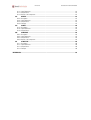
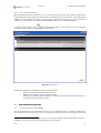
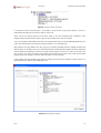
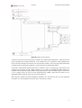
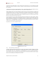
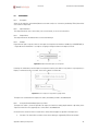
The main screen of the specifications generation tool is shown in Figure 2 and is divided into three main areas:
1. Menu: This saves wrappers, launches browsers to help generate wrappers and manages the display of
different task bars.
2. Browsing Area: This is where the projects created are displayed along with the wrappers for each project.
It also displays the list of components that can be used, including those provided by default by the tool and
those created by the user (see section 3.20 for further information). This area also allows for wrappers to
be exported to the ITPilot run server via the “Data Export Tool” tab. The “Tools” tab provides advanced
wrapper generation functions, as will be explained in section 3.17.
3. Workspace: This is the main area of the tool and is where the wrapper is graphically created by using,
configuring and relating the graphic components as a whole.
Figure 2 Specification Generation tool. Areas
Installation and Configuration
4
ITPilot 4.0
Generation Environment Manual
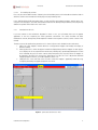
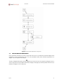
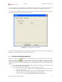
The browsing sequence generation tool can be seen in Figure 3. The function of each of the buttons and options will
be explained in detail in section 4, although the following areas can primarily be found:
Configuration: management and configuration of some of the ITPilot sequence generation commands.
Sequence Generation: These buttons allow for the graphic saving of the browsing sequence to be
used.
- Selection of Domain Values: A second bar appears, where the selection of values for a domain
previously created in ITPilot is necessary to complete specific fields in a browsing sequence (further
information on Domains can be found in section 4.7.2).
Figure 3 Sequence Generation tool
Below is a detailed description of both tools and how they complement each other. Firstly, a series of examples will
be given to explain the functions of the Specifications Generation tool (where an initial approach to sequence
generation is to be found). The second part of the manual will provide details on the Browsing Sequence Generation
tool.
Installation and Configuration
5
ITPilot 4.0
3
3.1
Generation Environment Manual
SPECIFICATION GENERATION MANUAL
INTRODUCTION
This section describes the Denodo ITPilot Specifications Generation tool that allows for Web wrappers to be created
in an easy and intuitive manner for non-technical users through a graphic application. The basic operation consists of
the use of graphic components to generate work flows for the automation of accesses to Web sources. These
components implement tasks such as the browsing of a certain page, the extracting of useful information based on
the provision of examples of user-tagged results, the iterating of results obtained for subsequent processing or the
describing of conditional flows.
The following pages explain the functions of this tool by generating an access wrapper for an e-mail Web source.
The first part of the example (as of section 3.2) will provide the basic and common capacities of almost any Web
wrapper, whereas the second (starting at section 3.15) focuses on more advanced matters that provide the tool with
greater power and versatility.
Specification Generation Manual
6
ITPilot 4.0
Generation Environment Manual
PART I
In this first part a complete and functional example is used to study the basic functions of the specification generator
tool.
3.2
PRESENTATION OF THE EXAMPLE
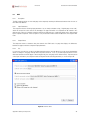
Figure 4 shows the home page of a Denodo Technologies e-mail Web site (accessed at
http://mail.demos.denodo.com). In this manual the specifications generator tool is used to obtain the list of incoming
e-mails (with an increasing level of detail) in a structured manner.
Figure 4 Denodo WebMail home page
Enter the UserName “demos” and the Password “DeMo.04” to access the Web e-mail application. The following
window will appear (Figure 5):
Part I
7
ITPilot 4.0
Generation Environment Manual
Figure 5 First message screen
The content of any e-mail can be accessed by clicking on the subject (Figure 6).
Figure 6 Content of a message
The Web application displays the messages 20 at a time, whereby to access the next messages you have to click on
the right arrow in
3.3
.
STARTING THE SPECIFICATION GENERATOR TOOL
After starting the tool (by executing the <DENODO_HOME>/bin/StartITPAdminTool.bat/.sh program or doubleclicking the “Start Wrapper Generator Tool” icon, if it was generated in the installation process), a window such as
that shown in Figure 2 appears.
Part I
8
ITPilot 4.0
Generation Environment Manual
An example is provided below to show how the application works. The objective is to obtain the e-mail list
automatically and in a structured manner.
3.4
CREATING A WRAPPER
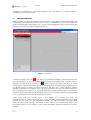
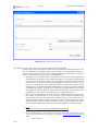
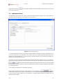
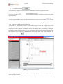
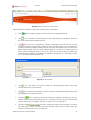
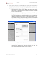
Wrapper programs must be created within the context of a project. These projects can be created, modified and
deleted from the ITPilot specifications generation tool. In this case, a “MAILWRAPPERS” project is to be created from
which the required wrapper will be created. To do so, click on “Project Management” in the tool’s Browsing Area and
the projects that currently exist will be displayed (see Figure 7).
Figure 7 Project creation
To create a new project, click on the
icon in “Projects”. The workspace will display a text field, where the project
name can be entered. In this case, call it “MAILWRAPPERS” and click on the OK button. Now see how the project is
symbol to the right of the project name allows for it to be
displayed in the Browsing Area (see Figure 8). The
deleted, where not required. Deleting a project involves eliminating all of its associated wrappers and, therefore, you
must be careful with your selection. On deleting a project the tool allows you to specify whether the wrappers
eliminated are deleted from the display tool only or also from the hard drive. If they are only deleted from the tool,
they will disappear from the project view. They can be retrieved by selecting the Refresh option from the project’s
contextual menu (by clicking with the right-hand button of the mouse on the specific project) or by selecting the Add
Processes option and then choosing the specific project to be retrieved.
Denodo ITPilot provides two templates, useful so that wrappers are not created from scratch. The
“StandardTemplate” one creates a wrapper to access a source and obtain structured information from the target
page and the “more results” ones. The “StandardDetailTemplate” ones adds the possibility of accessing a detail
page for every item from the main pages. Even though section 3.21 explains in more detail the maintenance issue, if
the wrapper requires no more components, these will be automatically maintained by ITPilot by using these
templates.
Part I
9
ITPilot 4.0
Generation Environment Manual
At last, these templates can be deleted by the user, if required.
The processes can be moved from one project to another using the “Copy to Project” or “Move to Project” options
from the contextual menu of each process. Besides, the processes can be migrated to different working environments
by
manually
copying
the
file
<DENODO_HOME>/metadata/itp-admintool/<project_name>/<process_name>.xml, where “project_name” is the name of the
Project where the process is stored, and “process_name” is the name of the project which will be migrated. It is
also possible to migrate a complete project, by copying the directory <DENODO_HOME>/metadata/itpadmin-tool/<project_name>
and
the
project
management
file,
<DENODO_HOME>/metadata/itp-admin-tool/<project_name>.xml.
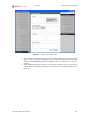
Figure 8 New project created
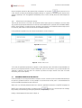
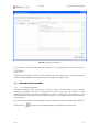
Once the project has been created, click on it to create a new process. This process will enable you to generate a
wrapper at the end of this example. Click on the
icon to give the process a name. In this case, the name will be
WEBMAIL. Figure 9 shows the result in the browsing area.
Part I
10
ITPilot 4.0
Generation Environment Manual
Figure 9 Creation of a new process
3.5
COMPONENTS IN ITPILOT
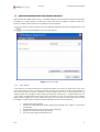
Once the project and the process have been created, you can start to develop them. To do so, click on the name of
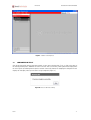
the recently-created process WEBMAIL to load it in the tool. After a short while, a dialog box will be displayed like
the one in Figure 10, indicating that the process has been successfully created. On accepting this dialog box the tool
displays the workspace, where you can start to assign components (Figure 11).
Figure 10 Success Load Process Dialog
Part I
11
ITPilot 4.0
Generation Environment Manual
Figure 11 Work area for Process Generation
In the browsing area you can see how the “Process Builder”->”Components” section has been automatically opened
with a list of general components that are distributed by ITPilot by default and an initially empty “Custom” list, where
the user-created components will be listed.
The more common general components will be explained in this manual. There is also a reference guide in section 6
of this manual. The reason why custom components are recommended and a description on how they are created are
explained in section 3.20.
The workspace is divided into three parts, as indicated below:
1. Components section: The general components are also graphically displayed at the top of the workspace. In
both cases, as indicated below, these components are used in the workspace by drag&drop.
2. Process generation section: This is the workspace itself, where users can drag components, relate them to
each other and configure them.
3. Component configuration section: This contextual area allows for the selected component to be configured.
The configuration of each component is divided into three parts: “Inputs”, where the input of data to the
specific component is indicated; “Wizard”, where each component with its specific characteristics is
configured, and “Details”, where its output (that may be collected as an input by another or other
components) is described along with other characteristics indicated below.
The workspace already displays two components as part of the current process. These components indicate the
process initialization and completion statuses. The initialization component is described in the following section,
although it is first necessary to explain the types of input and output parameters that can exist.
3.5.1
Input and Output Parameters
The following types of input and output parameters can be used by the components:
Part I
12
ITPilot 4.0
Generation Environment Manual
-
Pages: Some components such as the browsing sequence (Sequence) component return a page as the
-
Registers: Other components (e.g. the Record Constructor) return a structured group of information (in
result, which the other component will use to extract information, for example.
-
3.6
this example, this may be the structured representation of an information item).
Lists of registers: ITPilot allows for some components (e.g. the Extractor component) to return lists of
registers at their output or to accept them at their input.
Values: Other components return specific values at their output such as the Expression component.
PROCESS INITIALIZATION
The initialization component receives no parameters from any component, as it always starts the process. It is
responsible for storing the structure of the input data, which is the data that the wrapper will receive from the calling
application. For example, in this case, certain information is required by the e-mail application to access the
messages – more specifically, the user name and password values of the specific user. This data may be fixed or
variable so that different queries on the Web application use different values for these parameters. In this example,
it is to be variable and, therefore, must be defined.
The following steps are required to do so: First, select the initialization component using the left-hand button of the
mouse (see Figure 12).
Figure 12 Selection of the Initialization Component
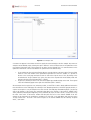
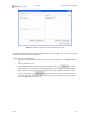
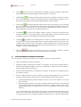
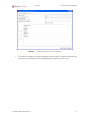
Click on the “Wizard” tab in the component configuration area and then on the “Open Init Editor” button to access
the Initialization Editor that will enable you to create an input register (see Figure 13). First, give this register a name
so that it is accessible to the rest of the process: MAILPARAMS. Then create the register elements by clicking on the
button next to the “Add New Field” section for each element and giving each one a name and data type. In this
case, two elements are created:
LOGIN, string-type and mandatory, which is obtained by ticking the “Mandatory” check box.
PASSWORD, string-type and mandatory.
Both elements are ticked as mandatory, as the Web application means that both fields must be completed.
Therefore, any time users wish to run on this wrapper, once generated it must contain values for both register
elements as input arguments.
The result of the action can be seen in Figure 13.
Part I
13
ITPilot 4.0
Generation Environment Manual
Figure 13 Initialization Editor
Now click on “OK” to return to the main window and you will see how the two recently-created fields appear in the
“Wizard” tab of the component configuration area (see Figure 14).
Figure 14 “Wizard” tab in the component configuration area with the initialization register already created
Part I
14
ITPilot 4.0
3.6.1
Generation Environment Manual
Use of the Catalog Explorer
Before continuing with process generation, this is a good time to insert a very useful tool to learn of the information
elements being processed at any given time in the process generation by any of its components. The Catalog explorer
enables you to see which registers, pages, views or lists exist at that time in a specific process in just one window.
Therefore, it is now possible to see whether the MAILPARAMS register has been created appropriately.
button appearing by default on the left-hand side of the component
To start the Explorer, click on the
configuration area1. A window will appear like the one in Figure 15.
Figure 15 Catalog Explorer
The following information is available for each type of catalog element:
Inputs: list of components with this element as input.
Outputs: list of components with this element as output.
Structure: Used in Register and List elements, this contains the description of the register structure (or
the inherent register in the case of the list).
3.7
3.7.1
WEB BROWSING AUTOMATION
Component Creation in the Workspace
Once the input parameters have been defined, the next step is to configure the process so that the wrapper knows
how to browse to the first user e-mails. To do so, the system must know how to access the main page of the e-mail
1 If you cannot find it, check that it is visible. To do so, go to the View->Toolbars menu and check that the “General”
check box is ticked. You can also press the combination of keys Ctrl+Shift+3.
Part I
15
ITPilot 4.0
Generation Environment Manual
application, enter the user Key and Password values and any other type of additional browsing until the first page of
results is accessed.
In ITPilot, the browsing tasks are primarily carried out by the Sequence component. This component is intrinsically
related to the Browsing Sequence Generation Tool, as it enables users to generate the sequence graphically, without
having to use the internal language NSEQL (see [NSEQL] for further information on this language) in most cases. The
wrapper generation tool is integrated into the Denodo ITPilot sequence generation tool so that browsing sequences
can be generated in this source description stage – of course, this sequence may have been previously saved and,
therefore, this step can be skipped. Even so, it is interesting to stop at this point to check how this tool integration
allows for domains to be automatically created in the browsing sequence tool -.
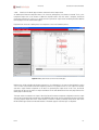
The process is as follows: First, drag the Sequence component either from the browsing area or from the workspace
icon. The Sequence component is displayed in the workspace. The default name can
component bar2 using the
be modified by double clicking on the component (in this example, it is called “InitialSeq”).
Now link the initial component to the sequence component to start creating the process flow. To do so, as indicated
in Figure 16, click with the left-hand button of the mouse on the initialization component connector and, without
releasing the mouse button, drag it to the sequence component input port (round in shape). Release the mouse to see
the connection between both components.
Figure 16 Relating components
3.7.2
Component Configuration
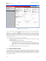
The sequence component can now be configured. To do so, once again select the component so that its configuration
area is loaded. In this case, the “Inputs” tab is enabled, as it can receive inputs from other parameters, more
specifically:
Input Values: input values to be used in Web browsing. In this case, it is necessary to select the
register created in section 3.6. To do so, click on the
the register “MAILPARAMS”.
icon of the “Input Values” element and select
2 If you cannot find it, check that it is visible. To do so, go to the View->Toolbars menu and check that the
“Components” check box is ticked. You can also press the combination of keys Ctrl+Shift+1.
Part I
16
ITPilot 4.0
-
Generation Environment Manual
Input Page: The Sequence component also allows for an input page from where browsing is to be done
to be indicated. This page must come from another component with a Web page as its output value,
such as another Sequence component or a Next Interval Iterator component. This is not necessary in
this example.
The Wizard tab enables you to access the Sequence Editor by clicking on the “Open Sequence Editor” button. This is
where the expected browsing sequence must be loaded. A browsing sequence is a set of NSEQL commands (see
[NSEQL] for further information) that describes different events on a Web browser (ITPilot 4.0 uses Microsoft Internet
Explorer 6.x in the generation environment). The browsing sequence can be created in two different ways:
Using the browsing sequence generation tool included in ITPilot. This tool (described in detail in
section 4 of this manual), integrated as a task bar in the Internet Explorer browser, allows for the
NSEQL program to be saved through user operations in the browser. This is the recommended way, as
it is more effective and fast.
Entering the sequence by hand in NSEQL. NSEQL is a relatively simple language to use and advanced
users may prefer this option. There are also Web pages that require advanced commands that are not
provided graphically by the sequence generation tool.
In this example, the sequence generation tool is used. To do so, open an Internet Explorer browser (either directly via
the Browser->New Browser option in the main menu or by pressing the combination of keys Ctrl-B). An Internet
Explorer browser window will appear with the browsing sequence saving bar (see Figure 17). If the bar does not
appear, check that the menu option “View -> Tool Bars -> Sequence Generator” is marked. Although this section does
not intend to give details as to how this tool works, the different steps will be shown in graphic form. For further
information, read section 4, which explains the way in which the sequence generation tool works, and [NSEQL].
Figure 17 Denodo Toolbar
Start saving by clicking on the
button and entering the browsing sequence home address (Figure 18):
Figure 18 Initial URL
The “Converter” selection list indicates whether the resource to be accessed via the URL is a Word or a PDF
document (it is left blank by default, which means that an HTML resource is expected). ITPilot is capable of
processing documents of this type through automatic HTML conversion.
After clicking on OK, the browser will display the home page (Figure 19):
Part I
17
ITPilot 4.0
Generation Environment Manual
Figure 19 Home Page
If you now enter the “UserName” and “Password” field values directly, the sequence generation tool will save them
as they are. However, the sequence saved is to be as general as possible, i.e. dependent on the input parameter
values. To do so, create a “Domain” in ITPilot (a domain is a set of key/value pairs), so that the sequence generation
tool can assign variables to Web page input elements (e.g. forms). Thus, the wrapper generated is able to accept
different values for different runs.
It is very simple to create domains graphically from the main window of the ITPilot wrapper generation tool. On the
left-hand side of the component configuration area, click on the “Domain Editor”
button that will open the
Domain Editor window (see ). Then click on the
button to add an example to the domain. As many examples as
required can be added, although in this case only one is needed. The name of the example (MAILPARAMS) will be
displayed on screen from the initialization data created in section 3.6. Underneath, specific example values for each
parameter will be entered. In this case, the input values of the e-mail Web application will be used, as indicated in
section 3.2:
LOGIN: demos
PASSWORD: DeMo.04
See Figure 20 to check it.
Part I
18
ITPilot 4.0
Generation Environment Manual
Figure 20 Domain Editor
Once the examples have been added, the domain must be exported so that the sequence generation tool can use it.
To do so, click on
(“Export Domain”) and select the name with which it is to be saved (by default:
MAILPARAMS.xml). Close the Domain Editor by clicking on “Close”.
Now use the recently exported Search Domain. Click on the
a dialog box will appear as shown in Figure 21:
button in the sequence generation tool and
Figure 21 Selection of the Search Domain
The list shows the existing domains. Click on the “MAILPARAMS” domain on the right side of the toolbar. A second
taskbar will appear under the original, where the data of the Search Domain exported from the specification
generator tool appear (Figure 22).
Part I
19
ITPilot 4.0
Generation Environment Manual
Figure 22 Search Domain Data toolbar
Now, instead of writing the data directly in the search fields “Username” and “Password” of the form on the home
page of the e-mail tool, a “Drag&Drop” operation transfers the values on the bar to the specific fields (text or
selection areas) of the form. The result can be seen in Figure 23.
Figure 23 Drag&Drop operation on the Main Page
In this way, the tool is capable of generating the necessary relations from the input parameters and the fields on the
HTML form.
Navigation continues until the results page is reached (Figure 5):
After checking that the semaphore icon is green, the sequence can be recorded so that it can be loaded into the
sequence component wizard, or by importing the sequence directly by clicking on the “Import from Browser” button.
It is recommended to save the sequence if it is going to be used in other processes. This is achieved by clicking on
the
button (calling it, for example, webMail.nsq) and stopping the recording process (
); once
the sequence has been recorded, it is loaded in the tool by pressing the “Load from File” button and selecting the
generated file. Figure 24 shows the result of the action.
Once loaded, the sequence can be altered, where necessary – which also implies that the navigation sequence can
also be handwritten, although in this case we recommend that you first read [NSEQL]. To do it, the altered sequence
can be modified in the area where the sequence resides.
Part I
20
ITPilot 4.0
Generation Environment Manual
Figure 24 Sequence editor with loaded sequence
This same figure shows how there are some configuration parameters. More specifically:
Sequence Type: ITPilot provides access to Web resources via different communication protocols. The
main ones are browser pool and http, whereas it is also possible to use the ftp protocol and access a
resource saved in the local file system. In this example, the browser pool type has been used, given
that this is a Web source with status. Each one is described below:
o browser pool: This is the default option. In this case, the sequence will be run using the browser
pool configured in the execution server in which the wrapper is run (see [USE]). The browser pool
uses browsers to run the NSEQL sequence. These browsers can be based on Microsoft Internet
Explorer, Firefox or on the use of a mini http client-based browser. In the first two cases, users do
not have to worry about tasks such as JavaScript treatment, etc. When the source does not use
JavaScript, the use of the http client-based implementation is normally just as effective, although
considerably more efficient. The browser pool included in the wrapper generation environment
uses minibrowsers based on Microsoft Internet Explorer and, therefore, if this option is chosen,
the wrapper tests (see section 3.14.2) will be carried out using these minibrowsers.
o http: This option uses the http client included in ITPilot for browsing sequences without using the
pool concept. As indicated, the use of an http client is more efficient and normally works
correctly, if the source does not use JavaScript. Through this option, it is also possible to use an
alternative syntax to NSEQL to specify the browsing sequences, simply indicating the request
mode (GET|POST) and the access pattern. In general, the access pattern will be the access URL,
which may include variables in the same form as the NSEQL programs (see [NSEQL]). Example:
POST
http://server.acme.com/login.jsp?login=@LOGIN&&pass=@PASSWORD
o
Part I
ftp: This provides access to the resource via ftp protocol. The format in which access to the
resource must be entered in the write area is as follows: ftp://login:password@domain:port,
where:
login: user name
21
ITPilot 4.0
-
-
-
Generation Environment Manual
password: password to access the ftp server
domain: specific address of the ftp server
port: port where the server is run (this is port 21 by default)
o local: Likewise, ITPilot provides access to resources in the local file system. The format to use is:
file://address3, where:
address: access path and resource name
Reuse Connection: Marked by default, this indicates whether the browser used to date is reused or
whether a new browser is launched, maintaining the session data. This option is generally marked,
although in some cases (such as when the Iterator component is used, as explained in section 3.12) it
may not be useful.
Maximum retries: As indicated in the next section, where the processing of errors of some type for this
component is configured to ON_ERROR_RETRY, this parameter determines the number of retries to be
made.
Time between retries: This indicates the time between one retry and the next in the event of the first
failing. The time is defined in milliseconds.
Figure 25 Result of the Sequence Editor
3.7.3
Output Data Configuration and Error Processing
To complete the configuration of this parameter, the “Details” tab determines the output name and the error
conditions:
Output Name: The output of a Sequence component is a page. The choice of name is important, as it
must be easily accessible by subsequent components using it as input. In this example,
INITSEQOUTPUT has been chosen.
Error conditions: This section configures the behavior of this component regarding certain error types:
o RUNTIME_ERROR: In light of a runtime error of the component, you can choose to ignore, retry or
publish and propagate the error.
o CONNECTION_ERROR: This error occurs when there is some kind of connection problem with the
source.
o SEQUENCE_ERROR: Error produced when there is some problem with the sequence (the
sequence is not correctly written, some command could not be run, etc.).
o HTTP_ERROR: Produced by an http error.
o TIMEOUT_ERROR: This error is produced if the Web source takes a long time to respond. The
waiting time is configurable. If the wrapper is used in the run environment, this parameter is
configured in the browser pool used (see [USE]). In the generation environment in question, this
value is configured in the ITPAdminConfiguration.properties file available in
<DENODO_HOME>/conf/itp-admin-tool,
with
the
property
IEBrowser.MAX_DOWNLOAD_TIME.
For this example, all of the values will be kept as ON_ERROR_RAISE, indicating that any error is reported and the run
completed.
3
Please note that the path can start with a “/” symbol. For example, Windows paths start by “/”, so in order to
access a specific directory, ftp:///c:/directory should be written.
Part I
22
ITPilot 4.0
3.8
Generation Environment Manual
STRUCTURE DEFINITION OF THE DATA TO BE EXTRACTED
Initially, the aim is to obtain the list of e-mails as they appear in the main page without worrying about obtaining
further details just yet (such as those obtained by clicking with the left-hand button of the mouse on each of the
messages). From the target page that the Sequence component obtained as a result, it is therefore necessary to carry
out a process to structure its relevant information after browsing.
. This
To do so, use another of the main ITPilot components known as Extractor, which has the following icon:
component generates an HTML page data extraction specification through the provision of examples by the user. This
means that the user does not have to use the internal language DEXTL (see [DEXTL] for further information), but by
merely providing the tool with some examples it is able to automatically generate the DEXTL program.
As usually, drag it to the workspace. It will use the information provided by the Sequence component and, therefore,
this must be interrelated. Lastly, the component is renamed “MainPageExtractor”. The expected result is shown in
Figure 26.
Figure 26 Using an Extraction Component
The first step in the component configuration process is the selection of the input page from where the component is
to extract structured data. This page is from the Sequence component (i.e. its output value INITSEQOUTPUT) and is
therefore found in the selection list (see Figure 27).
Once chosen, the Wizard tab generates the specification for this page based on examples provided by the user. This
matter is covered in further detail in the next subsection.
Part I
23
ITPilot 4.0
Generation Environment Manual
Figure 27 Input page of the Extractor component
3.8.1
Data Extraction Specification Generation
By clicking on the “Open Extractor Configuration” button, ITPilot opens a new window, the Specifications Generator,
as indicated in Figure 28.
Figure 28 Specification Generation Tool
The first step involves defining the output structure for the data extracted from the page (i.e. the type of data these
items have). The structure of an element may contain simple fields or hierarchically defined, nested subelements.
Part I
24
ITPilot 4.0
Generation Environment Manual
The user carries out this action on the first tab of the window, which is accessed directly when it is started for the
first time, known as “Structure”. In this step, using the options provided by the graphic interface, a tree is created
that represents the structure of the elements.
With Figure 5 in mind once again, the information of interest from each e-mail is as follows:
-
SENDER: the person to have sent the e-mail
SUBJECT: title of the message
MESSAGEDATE: e-mail reception date
SIZE: size of the message in KB
NOTE: there exists a set of ITPilot reserved words which can not be used as element names of the generated
structure. These keywords are shown in Table 1.
ADD, ADD_OBJECT_TO_LIST, ADMIN, ALL, ALTER, AND, ANY, ARRAY, AS, ASC, BASE,
CACHE, CATCH, CLEAR, CONDITION, CONNECT, CONSTRAINTS, CONTEXT, CREATE,
CREATE_LIST, CROSS, DATABASE, DATABASES, DATASOURCE, DATASOURCES, DESC, DF,
DISTINCT, DROP, ENCODED, ENUMERATED, EXCEL, EXISTS, EXPRESSION, EXTRACTOR,
FALSE, FETCH, FIELD, FILTER, FLATTEN, FOR, FORM_ITERATOR, FROM, FULL, GENERIC,
GRANT, HASH, HELP, HTML, I18N, I18NS, IF, INIT, INNER, INPUT, INPUTREWRITE,
INVALIDATE, IS, ITEM, ITERATOR, JDBC, JOIN, LEFT, LIST, MAP, MAPS, MERGE, MY,
NATURAL, NESTED, NEXT_INTERVAL_ITERATOR, NOS, NOT, NULL, OBL, ODBC, OF, OFF,
ON, ONE, OPERATOR, OPERATORS, OPT, OR, ORDERED, OUTER, OUTPUT, OUTPUTLIST,
OUTPUTREWRITE, PAGE, PATTERNS, POST, PRIVILEGES, QUERY, QUERYPLAN, RAW,
RAWPATTERNS,
READ,
RECORD,
RECORD_CONSTRUCTOR,
RECORD_SEQUENCE,
RECORD_STRUCTURE, REGISTER, REVERSEORDER, REVOKE, RIGHT, SEARCHMETHOD, SELECT,
SEQUENCE, SESSION, SIMPLE, STOREFILE, SWAP, TABLE, TRACE, TRUE, TRY, TTL,
TYPE, TYPES, UNION, USER, USERS, USING, VAR, VDB, VIEW, VIEWS, VQL, WHERE,
WHILE, WRAPPER, WRAPPERS, WRITE, WS, XML, XML2BIN, ZERO
Table 1
List of Reserved Words
These elements form the Web source data extraction structure. How to represent this in the specification generator
tool is shown below: when positioning ourselves in the structure tab, we must use the StandardHTMLLexer; if it does
not appear by default (under the “Current Scanner” text), we must select it and press the button
to set it up.
Even though it is not necessary for this example, for more information about scanners the user should read [DEXTL]
and section 3.17 of this Guide.
Once this step is completed, the structure can be created. First, give the type of record to be created a name by
double clicking on the text “(record name not set)” and entering “WEBMAIL”. The record type name is updated along
with the name of the specific structure. This name can be changed by double clicking on it (in this case on
“WEBMAIL_LIST”): In this example, it is called WEBMAILINSTANCE. Then, placing the cursor over each item and
clicking with the right-hand button of the mouse, it is possible to invoke the “AddChild” action that allows a new
item to be created. The “Change name” option or double clicking allows each item to be named as required. The data
type of each element can be defined using the “Change type” option. Create a structure like the one seen in Figure
29.
Part I
25
ITPilot 4.0
Generation Environment Manual
Figure 29 Extraction Structure
As can be seen in the advanced example, this hierarchic structure may be as complete as required by adding new
hierarchic levels depending on how the wrapper output structure is to be modeled.
The required “Tag Set” can be selected in each level. A tag represents a regular expression defined using HTML tags.
Usually, the tags are used to specify in the same manner basic representation primitives that can be expressed in
different ways in HTML. For example, we can define an ENDOFLINE separator as follows: EOL = ("<br>"| "</p>"|
"</tr>" | ”</td>” ([ \n\r\t])* </tr>”). A tag set is simply a group of tags. The “Standard” tag language is used by default,
which is valid for the vast majority of Web source extractions and is used in this first example. For more information
see [DEXTL] and section 3.17.
Click with the right-hand button of the mouse on the structure elements to view a contextual menu with the options
to change the name, add a new child node, delete the node and three other options described below:
- Aliases: Some types of wrappers can be automatically maintained by ITPilot (see [USE] for further
information). In these cases, the field enables users to assign words as synonyms or tags that can describe
this field in different environments to help the automatic maintenance system regenerate the specification,
if the Web source changes.
- Options: This modal dialog box provides two specific options:
o Regular Expression: This allows for a regular expression defining the representation format for
this element to be added. This is useful when the wrapper to be generated is to be maintained by
the ITPilot maintenance server and the value obtained is known to vary very frequently
(continuously, e.g. a stock exchange value). For further information on maintenance, read [USE].
The regular expression is defined in [REGEX]. This option is not used in this example.
o Date Pattern: Where the data type is Date, the specific pattern can be represented here using the
format defined in [DATEFORMAT]. In this example and in the case of the MESSAGEDATE field,
the DatePattern is defined as dd/MM/yyyy.
- Flat Level: When a record is multilevel (see section 3.8.2 for an explanation of this issue), it is possible to
indicate that you want the values of a certain level to be flattened, i.e. the attributes of lower levels to
appear in upper levels.
Part I
26
ITPilot 4.0
Generation Environment Manual
on the main menu to set
Once the complete structure has been created, click on the button “Set Structure”
it (the structure can always be modified by going back, although it is important to remember that this deletes all the
examples created up to now. The application automatically moves on to the next tab, where the Search Examples are
defined.
3.8.2
Nested Levels in the Component Structure
There may be nested levels in the data to be extracted schema. Figure 30 shows an example of an on-line music
shop, the data of which can be modeled in line with the schema ALBUM={TITLE, AUTHOR, DATE, EDITION:{FORMAT,
PRICE}}, where EDITION is a composed element. According to this definition, an EDITION value will be composed of a
list of records, where each one has two fields known as FORMAT and PRICE.
In the specifications generator tool, the structure would remain as shown in Figure 31.
Figure 30 Music bookstore
Figure 31 Structure of Music store
To this end, the specification generation tool provides a “level flattening” option. Click with the right-hand button of
the mouse on a compound element to view the “Flatten level” option. In cases like this one, you may want data to be
“flattened” to belong to the same level. The selection only affects the output structure of the data. For further
information, please consult [DEXTL].
3.9
ASSIGNING EXAMPLES OF THE RESULTS
In the second tab, the user may provide different examples of results so that the system can extract data according to
the previously generated structure. As many examples as desired can be inserted, and it is recommended that at
least two examples be provided for each of the levels.
Where users are sufficiently advanced and wish to write the specification themselves using DEXTL language (see
button to go to the next tab. In this example,
[DEXTL]), the system can be informed of such by pressing the
the possibility of automatically generating the specification through examples is used.
Initially, a window appears like that shown in Figure 32.
Part I
27
ITPilot 4.0
Generation Environment Manual
Figure 32 Result Examples Tab
A structure now appears in the window in which to specify the values belonging to the first example. Any amount of
examples can be added by simply selecting the option “Add Item” on the contextual menu of the right button on the
root element. Each atomic item of the structure has an option “Assign Selected Text” in its contextual menu on the
right button which allows a value to be added to this specific field in two different ways:
1.
2.
By associating text from an Internet Explorer browser, open by clicking on the menu option “Browser->New
Browser” in the main window of the specifications generation tool. From this window, it is possible to
browse to the results page and mark the text for each value using the mouse. Then, by clicking on the
aforementioned “Assign Selected Text” option, the value of the required field will be added, which will
appear to the right of the field name (FIELD = ‘VALUE’).
By previously entering the value in the text area displayed upon double clicking on the field. The assigned
value will immediately appear to the right of the field name (FIELD = ‘VALUE’).
We recommend the first option be used, wherever possible, so that ITPilot is able to obtain additional information
from the DOM tree of the HTML page, thus allowing a more adequate generation of the DEXTL program; besides, if
only the second option is used, all examples must come from the same web page. Remembering Figure 5, we can tag
each of the elements of the listing’s first email and relate them to the elements of the structure: SENDER (John
Smith), SUBJECT (Data Integration Approach), SIZE (1) and DATE (01/31/07). In order to do this, use the mouse to tag
the value “John Smith” in the browser window and then place the cursor on the element SENDER in the first
example of the third tab in the specifications generator tool, then click on the right button and select the option
“Assign Selected Text”. The result is that shown in Figure 33: the element SENDER has the following “Assigned
Value”, “John Smith”.
Part I
28
ITPilot 4.0
Generation Environment Manual
Figure 33 Assigning a Value to an Element
It is important to take into account that it is not possible to assign the text of any browser selection, since this is
determined by the tagset chosen in the first tab (see section 3.4).
Values can also be removed with the “Unset Value” option on the same contextual menu. Furthermore, entire
examples can be removed with the “Delete” option on the contextual menu of the root element.
Just as new examples can be added, occurrences from the hierarchical levels can also be added by placing the cursor
on the node which represents the level and selecting “Add Item” in its contextual menu.
New examples are always added in the same way, but it is generally advisable that these examples be taken from
different queries to the Web source (e.g. in electronic bookshops search by different subjects) and always taking care
that the specification generated (as will be seen later) correctly extracts all results out of each one of them; if this
does not occur, the system will require new examples which represent those query results which cannot extract
properly (giving more examples of elements that it can obtain is not of much help).
In this example, and after providing the first email as example, proceed with more examples to make the process for
generating the access pattern more reliable (Figure 34).
Figure 34 Assigning Various Examples
Part I
29
ITPilot 4.0
Finally, click on the button
phase: pattern generation.
3.10
Generation Environment Manual
to check that the examples have been properly inserted and move on to the next
GENERATING PATTERNS
Entering example results allows the system to generate the required extraction patterns. This is performed in the
“Generation” tab. The initial view of this window is shown in Figure 35.
Figure 35 Pattern Generation Window
It is presumed that by this time the user will have a suitable number of examples (see section 3.9). Where the user
has entered all the values of the examples, the tool will ask the user to specify the document from where these
examples are to be extracted (to do so, select some text in the frame with the mouse containing the examples in a
browser opened from the generation tool).
If, however, users do not provide any example for the generation tool having selected the “Do not use examples”
option from the examples tab, they will be responsible for generating the specification manually by clicking on the
button and writing the DEXTL program in the main window (this action is only recommended
for advanced users and/or in situations in which the advanced DEXTL functions not directly available from the graphic
tool must be accessed).
In this example, the specification is automatically generated.
Having already selected the element for which a pattern is to be generated, the
button
invokes the processing of those examples corresponding to this level and the documents that contain these examples
to return a group of DEXTL programs (for more information, see [DEXTL]). Before clicking on the button, the user
should consider two options:
Part I
30
ITPilot 4.0
Generation Environment Manual
-
Deleting false examples (by clicking on the checkbox:
[Delete false
examples]): when this option is selected, the system automatically attempts to detect false examples, i.e.
examples the user has accidentally entered (examples where data from several source examples have been
combined). This detection process can in some cases delete all examples, even those entered correctly,
whereby we recommend that you avoid selecting this option unless you suspect that the examples could
have been entered incorrectly.
-
): if this option is selected, the system tries to
Strict Patterns (clicking on the checkbox:
generate the most restrictive patterns possible. Specifically, the patterns will contain the bigger possible
number of text separators, instead of replacing them with elements of the type IRRELEVANT. If the user
does not select it, the system minimizes the number of IRRELEVANT elements and maximizes the use of
text separators. See [DEXTL] for more information. When should this option be used? In similar
circumstances than in the “Disambiguate” option: when more results than expected are being received.
-
): when the user selects this
Elimination of ambiguities (clicking on the checkbox:
option, the analyzer modifies the patterns of the DEXTL program generated by adding elements at the
beginning and end of each in order to recognize only those elements that most accurately correspond to the
selected examples –that is, the patterns are generated with more restrictions in order to avoid incorrect
extraction of data that do not match the provided examples-. When should this option be used? When the
generated specification has been checked and is seen to be getting more results than required. Other
alternatives are the use of the following option (“Strict Patterns”), and to manually introduce the elements
FROM and TO, which delimit the beginning and end of the extraction area (for more information on these
elements and their syntax, see [DEXTL] and section 3.18).
-
Pattern combination (clicking on the check box:
): This option is marked by default.
This option is extremely useful, when the source page requires the generation of a large number of optional
data elements, as it can reduce the necessary number of examples to be entered to a minimum.
Furthermore, the DEXTL program resulting from using this option is more compact.
When the Generation button is pressed, the DEXTL program text corresponding to this specific level appears on the
screen. See Figure 36 for a specific example on the home page of the Web e-mail application.
Figure 36 Generating a DEXTL Program
Part I
31
ITPilot 4.0
Generation Environment Manual
To check that the system properly recognizes all the DETAIL examples entered into the Result Example Definition tab,
once the Generation button has been pressed, the
button can be clicked. Figure 37 shows
the correct result of this test. It can be observer how the total number of obtained elements matches the number of
messages of the first page, and also, how there are no wrong elements; the window also shows the number of
recognized examples, matching the number of generated examples. The numbers between parenthesis point out
which of the generated examples have been found (in this case, the three of them: 0, 1 and 2).
Figure 37 Specification Execution test
If the retrieved results are not the desired ones, we have different options to evaluate:
• If fewer results than expected are obtained, new examples can be added from the examples that the
system has not extracted. It is also feasible to modify the existing examples.
• If more results than expected are retrieved, the options “Disambiguate” and “Strict Patterns” may be used
as explained previously.
• Alternatively, the generated DEXTL program can be modified manually (if doing this, we recommend users
to carefully read [DEXTL]); this option is selected by clicking on the
automatically generated program can now be modified.
Once the DEXTL programs of each of the levels have been satisfactorily generated, click on the
skip the “Marks” tabs which will be explained in detail in the advanced example available in PART II.
3.11
button. The
button and
GENERATING THE SPECIFICATION
In the Specification tab (Figure 38) the DEXTL programs of each level are generated together.
Part I
32
ITPilot 4.0
Generation Environment Manual
Figure 38 Specification Generation tab
In our example, as we have already tested the specification in the Generation tab, we just have to press the
button.
Configuration of the extraction component is now complete. Now simply change the name of the component output
element to EXTRACTIONOUTPUT from the Details tab of the component configuration area.
3.12
3.12.1
ITERATION OF RESULTS OBTAINED
Use of the Iterator component
The Extractor component returns a list of records as the result, each one of which contains one of the elements
obtained. In this example, each record is a message with its sender, message, date and size fields. In order to
manage them appropriately, each one must be obtained to set filters on specific fields, records, conditions, etc. The
Iterator component is used to iterate on each record in the input list. For each iteration, the component will return a
record from the list.
As usual, the iteration component can be dragged from the browsing area or from the workspace component bar. The
component icon is
Part I
. Figure 39 shows the graphic appearance of the component in the workspace.
33
ITPilot 4.0
Generation Environment Manual
Figure 39 Use of the Iterator Component
Configuration of this component is very simple. First, select the input list to feed the iteration process. In this case, as
can be seen in the above figure, the list corresponds to the extraction component output described in section 3.11,
EXTRACTIONOUTPUT. Then, from the Wizard tab, the iterator run mode can be configured. A parallel run can be
chosen in which each iterated element is propagated concurrently with the subsequent components. The other option
is the sequential run.
In the Details tab, it can be seen how the name of the output record corresponds to the name assigned by users in
the extraction component, as explained in section 3.8.1.
3.12.2
Individual record management
After configuring this component, the component receiving this iteration results record is added. In this specific case,
only each of the results is to be obtained to return them asynchronously to the application (i.e. as they become
available, without waiting for wrapper processing to have finished). To do so, another of the most important ITPilot
components is the so-called “Record Constructor” that, after receiving a set of records, is responsible for generating
an output record that may be the simple combination of those received or a modified version following the editing
and transforming/deleting of the fields of each one4. In this simple example, the data of interest concerning the only
input record is returned: sender, subject, date and size of message, although adding new attributes based on which
the date is returned so that the day, month and year values are returned separately.
4 Where no modification is to be made to the records returned by the Iterator component, the Record Constructor
component does not have to be used and the Iterator output can be linked directly to the input of the Output
component, which is explained below.
Part I
34
ITPilot 4.0
Generation Environment Manual
As usual, drag the component (the icon on the component bar is
) and add it to the process, as indicated in
Figure 40. Thus, the output records that the iterator returns after each iteration will be taken as input elements in the
Record Constructor component.
Figure 40 Use of the Record Constructor component
The component is configured as follows: Select the set of records that can be combined in this component from the
Inputs tab. In this case, only one will be used, the so-called WEBMAIL. Click on the
Values” to view a selection list from where “WEBMAIL” is chosen.
icon to the right of “Input
Once this has been done, access the Record Editor from the “Wizard” tab to build the component output record. In
this case, the WEBMAIL fields SENDER, SUBJECT, and SIZE are to be returned and three new fields, MESSAGEDAY
(that will return the day on which the message was delivered), MESSAGEMONTH (the month), and MESSAGEYEAR
(the year), created. All fields are disabled by default. In order to use them in the output record, simply click once with
the left-hand button of the mouse on the
again.
icon for each one. By clicking on the
icon, the field is disabled
icon to the right of the “Add new field” message to create new derived attributes. Click it three
Click on the
times and name each one as MESSAGEDAY, MESSAGEMONTH and MESSAGEYEAR, respectively.
Figure 41 shows the result of the operation after naming the output record.
Part I
35
ITPilot 4.0
Generation Environment Manual
Figure 41 Record editor
As can be seen, at the top of the window is an error indicating that some attributes have not yet been defined. New
fields created from existing ones can be added from the record editor. To do so, click on the
(e.g. MESSAGEDAY) to edit.
3.12.2.1
icon of any of them
Editing New Record Fields
icon and a new window will be displayed, as shown in Figure 42. In this window, it is possible to use
Click on the
the functions defined in ITPilot to apply them to the fields accessible from the Record Constructor component to
generate new derived attributes. Chapter 5 describes each of the functions available in ITPilot. In these cases, the
date treatment function GETDAY will be used, which accepts a DATE-type parameter as input and returns an integer
that indicates the day.
On the left of the screen are menus to create different values that can appear as operands in the expressions:
•
•
•
Constants. This menu allows constants of the different data types supported by Virtual DataPort to be
created.
Derived attribute functions. This menu allows for an invocation to one of the derived attribute functions
permitted by Virtual DataPort to be created. The functions can receive constants, attributes or the result of
evaluating other functions as parameters. They return one result. The list of available functions and use of
each one can be consulted in chapter 6.
Input Values. This corresponds to the list of attributes of the view to which the projection is applied. The
attributes can act as function parameters.
The central area of the screen (Values) allows for expressions to be constructed. The box on the left is a workspace
for creating new expressions, while the box on the right displays the expressions already created.
Finally, the “Expression” box contains the expression eventually created.
Part I
36
ITPilot 4.0
Generation Environment Manual
The following actions are required to create a new constant expression:
1.
2.
3.
Select the data type from the constant in the ‘Constants’ drop-down menu on the left of the screen and
click or drag&drop to the workspace, where expressions are created (left-hand box).
The type selected will appear in the workspace together with a text area to fill in the value of the constant.
The value required can be entered directly in the text area.
On clicking the ‘>’ button, the new constant will appear in the list of values created (upper right-hand box).
The following actions are required to create a new function-type expression:
1.
2.
Select the required function in the ‘Functions’ drop-down menu on the left of the screen and click or
drag&drop to the workspace for creating expressions (left-hand box). Place the cursor over the name of the
function to view its syntax.
The selected function will appear in the workspace together with an area to fill in the value of the
parameters of the function. The values of the parameters should be expressions present in the list of
created values (right-hand box) or attributes. To assign an expression already created as a parameter of a
function, drag&drop the expression created to the parameter area. By clicking on the ‘>’ button beside the
function, it will appear in the list of expressions created (right-hand box).
Figure 42 New record field editor
In this case, select the GETDAY function from the Functions area and drag&drop the MESSAGEDATE attribute from
the WEBMAIL record to the GETDAY function in the “Values” box. The result can be seen in Figure 43.
Part I
37
ITPilot 4.0
Generation Environment Manual
Figure 43 Creation of a derived attribute from the GETDAY function
Now simply click on the
button to move to the right-hand box. Given that no more are required, drag&drop the
result to the “Expression Value” field and click on OK. By carrying out this same operation with the other two record
attributes but using the GETMONTH and GETYEAR functions, the three new attributes of the output record will have
been generated. The result will be similar to that shown in Figure 44. Click on OK to return to the main window of the
Generation Environment.
Figure 44 Final result of the Output record
Part I
38
ITPilot 4.0
3.12.3
Generation Environment Manual
Returning of results
The operation is almost complete. Once the output record has been generated, the only thing left to do is use the
component to place the record in the process output. This “Output” component (
icon) is very simple to use, as
you merely have to indicate which record it has to place. In this case, the MAILMESSAGEOUT record returned by the
RecordConstructor component or, where no transformation was necessary, the record returned by the Iterator
component. Figure 45 shows the use and configuration of the component.
Figure 45 Use of the Output component
Figure 46 shows the complete process.
Part I
39
ITPilot 4.0
Generation Environment Manual
Figure 46 Complete process of the first part of the example
Part I
40
ITPilot 4.0
3.13
Generation Environment Manual
WRAPPER ADVANCED OPTIONS: BACK SEQUENCE AND LOCALE
Before finishing the wrapper creation process, some added capacities can be configured. Specifically, ITPilot allows
the addition of a “Back Sequence” to optimize the response time when the wrapper is executed several times;
besides, the default locale information of the wrapper can also be configured.
To do so, we use the last option of the left side of the component configuration area, called “Wrapper Options”, with
the
icon. A new window will appear such as the one at Figure 47.
Figure 47 Opciones del Wrapper
3.13.1
Back Sequence
In this window it is possible to define a browse sequence that enables you to return to a specific status of this source
in this search tab. This action is used when you define a browser reuse strategy to increase system efficiency. It
often occurs that browse sequences executed by a specific wrapper share a series of initial common steps. For
example, imagine that a wrapper has been created to automate the search process in a specific Web source. The
source requires an authentication process that involves the entering of a login and a password. In this example,
imagine that the wrapper uses the same key/password pair for all source accesses. Using Denodo ITPilot to create
this wrapper, an initial Sequence component would be created that would run the following steps:
1.
2.
3.
4.
5.
Part I
Connect to the source homepage.
Complete the authentication form with the login/password and click on the “Submit” or “Enter” button
to authenticate.
Once authenticated, click on the link accessing the search page.
Complete the search form with the required query.
The server returns a page with the query results.
41
ITPilot 4.0
Generation Environment Manual
The first three steps are common to all queries made to the wrapper. The difference between one query and the next
only arises in step four, when the search form is completed according to the specific query to be made at any given
time.
It would be nice to save time on these first three steps in each query: ideally, when a new query is received, one
browser is already authenticated and located in the search page of the source to which the new request could be
allocated. The browser searches immediately (step 4) and returns the results (step 5), thus avoiding time loss in steps
1-3.
A back browse sequence is responsible for returning a browser to a status in which it can be reused in future
requests by the same wrapper. Thus, when the wrapper in this example has made a query to the source, the browser
used to run the browse sequence remains on the query results page (step 5). For the browser to be used for a new
wrapper query, it must return to the search page (step 4). The sequence responsible for achieving this is the
aforementioned back sequence. A wrapper can obtain a back sequence in two ways:
•
•
Explicitly: the wrapper creator can specify a back browse sequence for a wrapper in the “Wrapper
Options” window, in the text field “Back Sequence”.
Implicitly: if the allocation strategy has been enabled in the STATE browser pool
(ASSIGNMENT_STRATEGY=STATE, see [USE]) and a wrapper does not have an explicitly defined back
sequence, then Denodo ITPilot will try to obtain a suitable back sequence for the wrapper by itself,
depending on the previous runs made. Normally Denodo ITPilot requires at least two wrapper runs before
being able to determine whether there is a back sequence suitable for the wrapper.
This back sequence will be taken by ITPilot as the first Sequence component of the wrapper. It is important to take it
into account when building the wrapper. Besides, the browser type used in this back sequence is implicitly chosen as
that selected by the first Sequence component of the wrapper.
Consult the Denodo ITPilot User Manual [USE] for further information on the reuse of browsers.
3.13.2
Locale
This area is used to configure the locale information of the wrapper. It incorporates support for the integration of
information from different countries or geographic areas, expressing the output data in the formats expected by the
country in question.
Besides, each Extractor component may contain its own locale configuration, taken into account even if it is different
to the default one.
There is an internationalization configuration for each of the countries/locations from which data can come. There
are several configuration parameters for each of the existing localizations. Some of the configuration parameters are:
coin, decimal and thousands separator symbols, date format, etc. ITPilot includes internationalization configurations
for the most common zones. The zone names correspond with the codes defined in standard ISO-639 [ISO639].
Examples: ES_EURO (Spain), GB (Great Britain),…
In the $DENODO_HOME/setup/vdp/metadata/properties/i18n path there is a file with the
configured parameters for every zone, used by the Generation tool. The internationalization parameters of a location
can be divided into various groups. The different groups are mentioned below, and each of the parameters
comprising same are described in detail:
NOTE: The internationalization parameters are case-insensitive. For instance, “timeZone” and “timezone”
correspond to the same key.
•
Generic parameters
•
Part I
language – Indicates the language used in this location. It is a valid ISO language code. These codes
contain two letters in lower case as defined in ISO-639 [ISO639]. Examples: es (Spanish), en
(English), fr (French).
42
ITPilot 4.0
•
•
•
country – Specifies the country associated with this location. It is a valid ISO country code. These
codes contain two letters in upper case, as defined by ISO-3166 [ISO3166]. Examples: ES (Spain),
ES_EURO (Spain with EURO currency), GB (England), FR (France), FR_EURO (France with
EURO currency), US (United States).
•
timeZone – Indicates the time zone of the location (e.g. Europe/Madrid for Spain = GMT+01:00
= MET = CET).
Currency configuration: Allows different properties to be configured for the money-type values.
•
currencyDecimalPosition – Number of decimals acknowledged by the currency in the location. For
example, for the euro this value is 2.
•
currencyDecimalSeparator – Character used as a decimal separator in the currency. For example,
the decimal separator for the euro is the comma.
•
currencyGroupSeparator – Group separator in the currency used for the location. For example, for
the euro the group separator is the full stop.
•
currency – Name of the currency. Example: EURO, POUND, FRANC.
•
moneyPattern – Specifies the currency format. In currency formats the comma is always used as a
separator for thousands and the full stop as a separator for decimal numbers. The character ‘¤’
represents the currency symbol and indicates in which place the character or characters that represent
it should be positioned. Example: ###,###,###.## ¤. The patterns defined by the
java.text.DecimalFormat class in the API standard Java Developer Kit are used to
analyze the currencies (see Javadoc documentation [JAVADOC] for more information).
Configuration of time-type data:
•
•
timePattern – Unit of time in which the values of this type are expressed in this location. The
possible values are: SECOND, MINUTE, HOUR, DAY, WEEK, MONTH and YEAR.
Configuration of dates: Configuration of data type date.
•
Part I
Generation Environment Manual
datePattern – Indicates the format for dates. To specify the format for dates ASCII characters are
used to indicate the different units of time. Table 1 shows the meaning of each of the reserved
characters used in a date format, their arrangement and an example of use. Example of a date format:
d-MMM-yyyy H'h' m'm'. For more information, please read [DATEFORMAT], classes
java.text.DateFormat and/or java.text.SimpleDateFormat.
43
ITPilot 4.0
Symbol
G
y
M
d
h
H
m
s
S
E
D
F
w
W
a
k
K
z
'
''
Meaning
Specifies an Era
Year
Month in year
Day in month
Time in a.m./p.m. (1~12)
Time in day (0~23)
Minute in hour
Second in minute
Millisecond
Day of the week
Day of the year
Day of the week in the month
Week of the year
Week in month
a.m./p.m. tag
Time in the day (1~24)
Time in a.m./p.m. (0~11)
Time zone
Escape character for text
Single inverted comma
Table 2
Generation Environment Manual
Arrangement
(Text)
(Number)
(Text & Number)
(Number)
(Number)
(Number)
(Number)
(Number)
(Number)
(Text)
(Number)
(Number)
(Number)
(Number)
(Text)
(Number)
(Number)
(Text)
(Demarcator)
(Literal)
Example
AD
1996
July & 07
10
12
0
30
55
978
Tuesday
189
2(2nd Web in July)
27
2
PM
24
0
Pacific Standard Time
‘
Reserved Characters for Date Format
In Table 2 different values are used to indicate the arrangement of reserved characters. The specific
output format depends on the number of times the different elements are repeated:
o
Text: with 4 or more characters to use complete form; less than 4 characters to use the
abbreviated form.
o
Number: uses the minimum number of digits possible. The 0s are added to the left of the
shortest numbers. The year is a special case: if the number of ‘y’ is 2, the year is shortened to 2
digits.
o
Text & Number: 3 or more characters to represent it as text; otherwise a number is used.
In a date format the characters that are not found in the ranges ['a'..'z'] or ['A'..'Z'] are
considered text in inverted commas, i.e. characters such as ':', '.', ' ', '#' and '@' appear in
the resulting date, although they are not in inverted commas in the format text.
•
3.14
3.14.1
Configuration of real numbers: Facilitates the configuration of the data types float and double.
•
doubleDecimalPosition – Indicates the number of decimal positions to be used to represent a
double-type or float-type value (real numbers).
•
doubleDecimalSeparator – Represents the decimal separator used in a real number.
•
doubleGroupSeparator – Specifies the group separator for real numbers.
WRAPPER GENERATION, TESTS AND EXPORTING
Wrapper Generation
Once the graphic creation of the process is complete, it can be tested. To do so, the wrapper must have been
generated. ITPilot compiles the flows defining the wrappers to programs expressed in JavaScript [JS] language. This
(“JavaScript”) button on the General bar to the left of the component
is generated by clicking on the
configuration area. If everything is correct, a modal window will be displayed indicating that the JavaScript code has
been generated successfully. Click OK on this window and another will be displayed containing the code, as shown in
Figure 48. The code can be edited from this window, should any modification have to be made, or it can be
Part I
44
ITPilot 4.0
Generation Environment Manual
regenerated. However, bear in mind that the changes made to the Javascript code will have no effect on the
component flow. If you decide to regenerate the JavaScript associated to the flow, any changes made to the code
will be lost. Read [JSDENODO] for further information on the code generated by ITPilot.
Figure 48 JavaScript code of the generated wrapper
3.14.2
Wrapper Execution
With the wrapper generated, it can now be tested. To do so, click on the
(“Test Wrapper”) button in the main
window. A window like the one shown in Figure 49 will be displayed. This test tool consists of three tabs. The first,
“Input Values”, enables users to enter example values for each of the wrapper input parameters (as defined in the
initialization component in section 3.6).
Part I
45
ITPilot 4.0
Generation Environment Manual
Figure 49 Wrapper testing tool
Furthermore, it also allows for the trace level of the wrapper run to be selected. You can choose from among FATAL,
ERROR, WARN, INFO, DEBUG and TRACE. The use of the DEBUG level is recommended when testing the wrapper for
the first time.
button, the editor goes to the “Execution Trace” tab and launches a
By clicking on the
browser (as the browsing type was defined as ‘browser pool’ in section 3.7.2 and the generation tool uses a browser
pool based on Microsoft Internet Explorer), which starts to browse through the pages defined in the Sequence
component (section 3.7). On reaching the message page, the Extractor component (section 3.8) obtains the list of
records, after which the iterator (section 3.12) passes the individual records to the RecordConstructor (section 3.12.2)
and this, in turn, to the Output (section 3.12.3). The tab displays the different trace messages that the specific flow
can follow. During the execution, the button is transformed to
stopped at any moment.
, thus allowing the running to be
Lastly, following wrapper execution, the “Results” tab displays the results it has returned. In this case (Figure 50), it
can be seen how the wrapper returns the results on the e-mail message Web page. Wrapper generation has been
successful.
The values of the input parameters of the wrapper are maintained from one execution to the following. Besides, it is
possible to import values from the domain editor, by dragging the field name in the editor and dropping it in the
wrapper execution dialog field name.
Part I
46
ITPilot 4.0
Generation Environment Manual
Figure 50 Results returned by the wrapper
Before continuing, save the process (File->Save) to avoid the loss of valuable information and to be able to modify or
add functions in the future.
3.14.3
Wrapper Exporting
With everything operating correctly, the last step consists of preparing the wrapper for operations in the ITPilot run
environment. There are two alternatives for this: direct exporting from the generation environment to the run
environment (which means that the run environment must be started at the time of exporting) or the saving of the
wrapper to the local file system in VQL format (which is the ITPilot wrapper run format) for subsequent loading in the
run environment.
3.14.3.1
Deployment in the run server
From the main window of the ITPilot wrapper generation environment, click on “Data Export Tool” in the browsing
area. This opens two more elements in this same area, “VQL Generator” and “Server Deploy”. Click on the second
option and configuration data will appear in the workspace, as shown in Figure 51).
Part I
47
ITPilot 4.0
Generation Environment Manual
Figure 51 Wrapper deployment in an ITPilot execution server
Now enter the server access data and its URL (//localhost:9999/itpilot by default), login and password. The server
data may correspond to that of a Denodo Virtual DataPort server [VDP], so that the wrapper can be used as another
source in any data integration process. To do so, click on the “Create Base Relation” option and complete the field
called “Base View Name” with the name of the base view that will now reference the recently created wrapper in
Virtual DataPort. For further information, consult the Denodo Virtual DataPort documentation [VDP]. Besides, ITPilot
allows to configure whether the user wants it to be maintained or not. Click on OK and, on the premise that the
execution server is started, the wrapper will be deployed. For further information on the ITPilot execution server, read
[USE].
3.14.3.2
VQL generation for subsequent loading
From the main window of the ITPilot wrapper generation environment, click on “Data Export Tool” in the browsing
area. This opens two more elements in this same area, “VQL Generator” and “Server Deploy”. Click on the first
option and configuration data will appear in the workspace, as shown in Figure 52.
Part I
48
ITPilot 4.0
Generation Environment Manual
Figure 52 Wrapper storage in a local file system
Now enter the name to be given to the wrapper (e.g. WEBMAIL). The wrappers can then be loaded in the ITPilot run
server using the ‘Load VQL File’ option in the ITPilot Web administration tool. See [USE] for further details.
The wrapper can be used as another source in any data integration process in Denodo Virtual DataPort [VDP]; to do
so, the option “Create Base Relation” must be clicked, and the “Base View Name” field must be filled with the name
of the base view that, from that moment on, will point out to the wrapper in DataPort. For more information, it is
recommended to read the Denodo Virtual DataPort documentation [VDP], Besides, the user can configure whether the
wrapper is going to be maintained or not. Pressing OK, ITPilot will store the file anywhere in the local file system.
This is the file to be used to deploy the wrapper in the execution server. For more information about ITPilot execution
server, please see [USE].
Part I
49
ITPilot 4.0
Generation Environment Manual
PART II
This second part shows how to make optimum use of the tool to obtain more complex wrappers.
3.15
EXTRACTING MULTIPAGINATED DATA
Most Web sources present results in various consecutive pages, all with the same format. Any electronic shop or
Internet search engine can return hundreds or thousands of results in this manner, whereby in order to obtain an
ample subgroup of data from a specific source, you have to browse through this sequence of “more results” pages.
To do so, the ITPilot specifications generation tool provides a browsing component known as “Next Interval Iterator”
that iterates on different pages with a similar structure. Therefore, instead of browsing to a certain page using the
Sequence component and running the Extractor component on it, you browse to this page using the Sequence
component, and a loop is started in which, every time the Extractor component has extracted data from a page, the
next interval iteration component will access the next page of results using a browsing sequence defined in this
component. Below is a description of these steps in the generation tool.
Drag&drop the Next Interval Iterator (
) component to the workspace and connect it to the previously created
process in the way shown in Figure 53. The changes made are as follows:
1. The Sequence component sends its output to the starting element (“Next_Interval_Iterator”) of the Next
Interval Iterator component.
2. This starting element is related to the Extractor component that, in the previous example, was directly
connected to the Sequence component.
3. The ending component is no longer connected to the Iterator ending component, but to the Next Interval
Iterator ending component (“Begin_Next_Interval_Iterator”).
Part II
50
ITPilot 4.0
Generation Environment Manual
Figure 53 Use of the Next Interval Iterator component to browse more pages of results
The component can now therefore be configured. In the Inputs tab of the component’s “Next_Interval_Iterator”
element configuration area, the input page from which browsing for more intervals is to be carried out can be
indicated. Furthermore, input records can be assigned to the component. These records are used when the browsing
sequence has variables. ITPilot will use the values of the record attributes with names that match the name of the
variable used in the sequence.
The Wizard tab enables users to access the next interval editor. This editor is very similar to the sequence editor
described in section 3.7.2, although with certain distinguishing features described below. First, let us see how to
generate a browsing sequence to obtain further information on messages not residing in the main page but in the
following pages of results. Figure 54 shows the home page of results. At the bottom right, you can see a series of
links that enable you to browse to the following pages of results. Therefore, save a browsing sequence and click on
the next page button. This sequence will be used by the component at the end of each iteration to access the next
page, so that the Extractor component continues to obtain results.
We will therefore open a Microsoft Internet Explorer browser. Click on the button
and when the dialog in
which the start navigation sequence address has to be written appears, close it by clicking on
or by leaving
the URL blank and clicking on OK. We are now recording on the current page. In the navigation panel
(
Part II
) click on the arrow
“Next Page”, which brings us to the next results page. Click on the
51
ITPilot 4.0
Generation Environment Manual
button to record the sequence (e.g. correoWeb.next.nsq) and stop the recording process with
.
Figure 54 Webmail result page
Now, we can go back to the Next Results Sequence editor and load the new sequence by pressing the
button.
The rest of the editor has the following configuration capacities:
- Sequence Type: As with the Sequence component, this can determine the type of access to be made,
whether via a browser, an http client, the FTP protocol or a resource residing in the local file system.
- Repeated Sequence/Different Sequences: Although Web sources in general often replicate the way of
accessing the following results from one page to another, this does not have to be the case. To do so,
ITPilot allows for a set of different browsing sequences to be generated, one for each iteration made. This
is not necessary in this example and, therefore, the “Repeated Sequence” option will remain marked.
- Sequence Repetitions: This parameter determines the number of times the browsing sequence is to be run
(i.e. the number of pages of results to be covered as of the main page). For example, if “2” is entered,
ITPilot will try to click twice (and the wrapper would extract data from three pages of results in total).
- Reuse connection: Marked by default, this indicates whether the browser used to date is reused or whether
a new browser is launched, maintaining the session data. This option is generally marked, although in
some cases (such as when the Iterator component is used, as explained in section 3.12) it may not be
useful.
- Maximum Retries: This parameter determines the number of retries to be made.
- Time between retries: This indicates the time between one retry and the next in the event of the first
failing. The time is defined in milliseconds.
The effect of these last actions can now be seen retesting the wrapper, as was the case in section 3.13. The result –
once the system has accessed the next pages of results – is shown in section 3.13.
Part II
52
ITPilot 4.0
3.16
Generation Environment Manual
ACCESS TO DETAILS PAGES
3.16.1
Introduction
Until now, we have developed a specification that allows the list of messages that appear on a page of a Web e-mail
application to be obtained in a structured manner. However, we already know that on this page only a sub-group of
data for each message appears. Elements such as the message body, the absolute date, carbon-copied senders or
attached data appear in the detail page of each of the messages.
In this section we commence the modifications that need to be made to the example already used in order to make
all these data available.
The structure now required is the following:
- MESSAGEDATE: date the e-mail was received
- SENDER: who sent the e-mail
- SUBJECT: message title
- SIZE: size of the message
- MESSAGE: content of the e-mail
As can be seen, the elements SENDER, SUBJECT and SIZE are maintained. However, new fields are added such as
MESSAGE (that is obtained from the detail pages). Likewise, the MESSAGEDATE field is maintained, but it will also
be obtained from the detail page.
We must, therefore, modify the process in order to add those components that allow the browsing to each one of the
detail pages; besides, we will have to modify some of the already existing ones.
3.16.2
Field Modification in the Extractor component: DATE field
The Extractor component created in section 3.8 obtained the values of the SENDER, SUBJECT, MESSAGEDATE and
SIZE fields for the message. This component is now modified to delete the MESSAGEDATE field (that will be
obtained from the details page).
The DEXTL program must then be regenerated by providing examples. ITPilot requires as such, as the adding or
deleting of fields may modify some of the specification patterns. Luckily, the process remains as simple as in section
3.8:
1. Open a browser from the Browser->New Browser option (or pressing Ctrl-B) in the main page menu of the
wrapper generation tool.
2. Browse to the page of results (that shown in Figure 5).
3. Drag&drop the example values to the specific fields of the structure displayed in the “Examples” tab of the
Extractor component editor.
4. Generate as many examples as required. In this case, three examples are generated, as the structure of all
the results is similar.
5.
Go to the next tab by clicking on the
button.
Figure 55 shows how the examples are assigned in the new structure before going to the next tab.
Part II
53
ITPilot 4.0
Generation Environment Manual
Figure 55 Assigning examples in the new structure of the Extractor component
The DEXTL program is generated in the same way and is tested as in section 3.8.
3.16.2.1
Assigning Tag Attribute Values
Until now, the specification generator tool has allowed us to extract data that could be directly obtained by viewing
the Web page in the browser. However, on some occasions, we may wish to extract values from HTML tag
attributes. For example, you may want to include the “href” tag value of a link in a simple field (remember that if the
value of this tag is a relative link, the corresponding level will have to store the base URL from which it sets out).
In this case, it may be wise to save the URL accessing the message detail data. To do so, use the Tags tab in the
Extractor component wizard (see Figure 56).
Part II
54
ITPilot 4.0
Generation Environment Manual
Figure 56 Tab for Assigning Tag Attribute Values
At this stage, the values of the tag attributes required are assigned to simple fields for the extracted elements. Users
carry out the following steps:
1.
2.
3.
4.
Select the pattern in which the tag attribute is to be found (DEXTL allows for different patterns to be used
within the same specification to provide options, for example. See [DEXTL] ).
Select the tag for which the attribute is to be included in the workspace.
From all those possible, select the attribute required for this type of tag (e.g. only the URL attribute is
defined for ANCHORs).
Lastly, choose the field in which the value of the tag is to be included.
For the example of the Web mail application, the specific actions to be carried out are those described below. As a
previous step, a new attribute must be created in the record of the extractor component. This can be called
SUBJECT_URL5:
1.
2.
3.
list, select the only
In the
example.
As can be seen in Figure 56, the main window of the tab shows the different
selected pattern, whereby the tag from which the attribute is to be collected
mouse.
In
this
case,
click
on
the
ANCHOR()
tokens that make up the
can be tagged using the
that
appears
in
(it changes color)
The required attribute in this case is “URL” – the only option –, and this is selected in the
list
4.
pattern available in this
In
included (in this case, SUBJECT_URL).
.
select the field in which the tag value is to be
5
The update of the structure of an Extractor component implies the repetition of all previous steps (example
assignment, specification generation and mark assignment).
Part II
55
ITPilot 4.0
5.
To end click on the button
Generation Environment Manual
.
The assignment result appears in the main window as a modification of the DEXTL program shown earlier.
By selecting the option
tag can be deleted.
the attributes assigned to the selected
As always, once the attribute values of the required tags have been assigned, click on the button
on to the Specification tab.
3.16.3
to move
Access to the Details Page from the Main Page
The aim now is to build the browsing relation between the main page of results and the details page for each
message. Once the Sequence component has obtained the page of results, it is sent to the Extractor component to
generate a list of records, each one of which represents one of the e-mail messages on that page. A new component
known as Record Sequence can now be used, which provides access to pages related to others or pages with access
provided by previously extracted records. In this case, the component input will be the Sequence component output
page created in section 3.7 (known as INITSEQOUTPUT) and the output record of the iterator (WEBMAIL). This
component, represented by the
icon, is displayed in the workspace of Figure 57.
Figure 57 Use of Record Sequence component
Using the Wizard tab, configure the access sequence to details pages by means of the record sequence editor. This
editor is divided into two tabs:
Part II
56
ITPilot 4.0
1.
2.
Generation Environment Manual
Commands: This tab configures the command or commands required for browsing from the source page or
record to the required details page.
Sequences: This tab is responsible for characteristic configuration tasks such as the back sequence or what
is known as “global form management sequences” in ITPilot, which will be explained later on.
In the area at the top of the window, the Commands tab displays the DEXTL specification of a record obtained from
the main page using the data provided by the Extractor specification (to do so, the Record Sequence must be directly
or indirectly connected to the Iterator providing each of the records for that extractor). Although you should read
[DEXTL] for a full understanding of this language, it is intuitive enough for the meaning of the following tags to be
understood, observing Figure 58: The first, known as ANCHOR(), indicates that the SENDER attribute (identified as an
attribute by the character “:” as a prefix) has a link (which can be seen in Figure 5, where the sender data contains a
link to the message details page). The ENDANCHOR() tag indicates the end of that link. There is also the TAB() tag
that indicates the existence of some kind of tab in the HTML page. The SUBJECT attribute saves the message subject
and is wrapped by a link to also access the details page for this message. Finally, there is another tab tag known as
the SIZE attribute and a fixed text “kb”.
ITPilot allows for a graphic indication to access a new page by clicking on one of the links displayed in the
specification. The way in which the Record Sequence component is indicated the manner of accessing the details
page from the main page is as follows: Double click on one of the ANCHOR tags (on the second in Figure 58), so that
ITPilot assigns the value corresponding to the URL of the link to a dynamically generated attribute.
Figure 58 Record Sequence editor
By double clicking on one of the ANCHOR tags, a line known as ANCHOR is added in the lower workspace (known as
“Current Commands”). The sequence editor allows for further processing commands to be added, although in this
case it is not necessary, as the link simply has to be followed. In other occasions, it may be necessary to carry out an
additional action (e.g. selecting a check box before following the link).
Where the ANCHOR is selected at the bottom and the
button clicked, a new window will be opened, as
indicated in Figure 59. Here it is possible to modify the NSEQL program generated by ITPilot by default in the event of
Part II
57
ITPilot 4.0
Generation Environment Manual
alternative behavior being required. To do so, please read [NSEQL]. This will not be necessary in this example, as the
Web application will access the details page by merely clicking on this link. It is also possible to configure the
number of retries that this sequence can run in the case of access error on this page.
Figure 59 Record Sequence component Command Editor
The Sequences tab of the record sequence editor allows for advanced configurations on the browsing sequence
defined in the previous tab:
1. Sequence type: As explained in section 3.7.2, different access protocols to the HTML resources to be
browsed can be defined. It is important to note that the access types for one sequence or another or in the
use of a Record Sequence may be different.
2. Reuse connection: By ticking this check box, ITPilot is informed to use the same browser used until now in
the process. This is basically for efficiency purposes. Where it is not marked, ITPilot will launch a new
browser and export the session data of the browser used until then to the recently created (this is useful
and necessary when, for example, parallel runs are made in an iteration).
3. Use of the Back Sequence: There are two boxes and a workspace related to this function. ITPilot enables
users to decide whether to transfer the responsibility of going back to the previous page after each
iteration on details pages to ITPilot or whether the users themselves will provide a specific browsing
sequence or, what is more, whether to go back to the main page or not. The following graphic elements are
used:
a. “Use Custom Back Sequence” check box. This is marked when a back sequence is to be used to
go back to the previous page. If it is not marked, ITPilot will generate a navigation to the previous
page with the same browser through an HTTP POST or GET method. This action is usually slower
than the navigation by means of a sequence. It is important to emphasize that the back sequence
will be performed at the beginning of the following iteration, not at the end of the current one.
b. “Default Sequence” check box. This is only enabled when the previous box has been marked. It
informs ITPilot that the default sequence will be used, which consists of carrying out a “Back”
action (as if the “Back” button on the browser had been clicked).
c. Where the previous box is not marked, the user may load a specific browsing sequence using the
“Load from File” or “Import from Browser” buttons, as indicated above in the Sequence
component (see section 3.7).
4. Global Form Sequences: Sometimes, the actions carried out on each result from a Web page to access
other pages (e.g. the details pages of this example) all belong to a single form. This means that, before
being able to click on these links, ITPilot must find the form to which they belong in order to identify it and
to know, where necessary, how to run it (e.g. by clicking a “Submit” button or that of a specific link). In
Part II
58
ITPilot 4.0
Generation Environment Manual
these cases, ITPilot allows for browsing sequences to be added for the actions prior to running the
sequence in the “Global Form pre Sequence” area and for subsequent actions in the “Global Form post
Sequence” area. The sequences can be entered by hand, although the “Load from File” and “Import from
Browser” buttons mean that a browsing sequence can be imported. ITPilot will search the first
“FindFormByXXX”-type command (see [NSEQL]. for further information) and will copy everything above this
command, FindFormByXXX including, to the “Global Form pre Sequence” area and everything after it to
“Global Form post Sequence”. See [NSEQL] for further details on NSEQL commands.
3.16.4
Back Sequence in the Browsing Components
The possibility of defining the behaviour of the back sequence exists in every browsing component, specifically:
Sequence –see section 6.20-, Next Interval Iterator – see section 6.14-, Form Iterator – see section 6.10- and Fetch –
see section 6.8-). This option is useful to control the browser behaviour in cases such as retries, page refresh actions,
and so on. Figure 60 shows the “Advanced” tab in this components’ configuration wizard. The Record Sequence
component, now being explained, has this option fully integrated in the “Sequences” tab, as it has been described in
the previous section.
Figure 60 Advanced Tab for Back Sequence definition
3.16.5
Individual Test of the Record Sequence Component
Figure 61 shows the results of the sequence configuration of the Record Sequence component in our example.
browserpool shall be used as the sequence type and ITPilot will be left to generate the back sequence. The browser
connection will be reused and the use of pre- and post-sequences will not be required, as there is no global form in
the page of results.
Part II
59
ITPilot 4.0
Generation Environment Manual
Figure 61 Configuration of Sequences with the Record Sequence component
This component can be tested without having to compile and test the entire wrapper. This is also the case with the
FormIterator and Next Interval Iterator components.
The following steps are required to do so:
1. Open a browser from the Browser->New Browser option in the main page menu of the wrapper generation
tool.
2. Browse to the page of results.
3.
In the configuration window of the Record Sequence component, click on the
button. ITPilot
will transfer the session data from the Internet Explorer browser to an ITPilot browser, loading the same
page. It will also launch a component test window like the one shown in Figure 62.. From here, it can be
button, the ITPilot browser accesses the details page for
seen how, by clicking on the
each result, as required. The window displays the trace of the run, as would occur in the run test window
of the full wrapper shown in section 3.14.2.
Part II
60
ITPilot 4.0
Generation Environment Manual
Figure 62 Test window of the Record Sequence component
3.16.6
Extracting data from the details page
Once ITPilot is able to access the details page for each message, it is now time to obtain the data of interest from
this page. To do so, use an Extractor component once again, as when data was to be obtained from the first page of
results (see section 3.8). Use of the component in the process is shown in Figure 63. The component input is the
output of the Record Sequence component known as DETAILPAGE.
Part II
61
ITPilot 4.0
Generation Environment Manual
Figure 63 Use of the Extractor component to obtain information of the detail pages
In our example, the Extractor component responsible for extracting information from the detail page will contain at
least one element (“MESSAGE”) that may contain “<BR>”-type HTML tags as well as links. Therefore, the
“STANDARD” tag set of the StandardHTMLexer scanner, used by default in the Extractor, is of no use, as it would
find patterns within the message, so we would not be able to extract the complete message into a single attribute.
Therefore, the detail level must have a different tag set. Section 3.17 shows how the graphic tool can generate a
new tag set associated with a specific scanner6. Read [DEXTL] for a better understanding of the scanner and tag set
concepts.
3.16.7
Generating the Access Specification to the Details Page
Once the new scanner and the tag set have been generated and the new structure is established, go to the Examples
tab by clicking on the
button, where the examples are assigned. It can be seen how in this case the text of
the message can be assigned to the MESSAGE attribute on using the new tag set. Where a message contains HTML
tags belonging to EOLLINEBREAK, the existing text may only be assigned to that tag. Where necessary,
EOLLINEBREAK may be modified so that it can also be accepted.
Once the examples have been assigned, go to the generation tab. This tab contains a function that has not yet been
indicated and that is quite useful: FROM/UNTIL pattern generation.
6
This tag set really already exists in the ITPilot distribution. It is the “STANDARD_TEXTFRAGMENT” tag set that
belongs to the “StandardLexerJS” scanner.
Part II
62
ITPilot 4.0
3.16.8
Generation Environment Manual
Iteration on the details page structures and creation of the output record
As indicated, the Extractor component returns a list of records, although only one element is returned. To do so, the
component output must use an Iterator to obtain the required records. Once this action is complete, the Record
Constructor component of section 3.12.2 can be reused to generate an output record containing the data obtained
from the pages of results and the details pages.
Figure 64 shows the result of adding these last components to the e-mail extraction process.
Figure 64 Adding a data Iterator comino from the detail pages
Nothing more will be said about the Iterator component, as its configuration is the same as that indicated in section
3.12.1. In terms of the Record Constructor component, section 3.12.2 explains how to use it as output of an iterator
and with a single Extractor component as the basis for generating the output record. In this case, the Record
Constructor will be used to create an output record based on the data obtained from the main page and from the
details page of each message.
Two input values are created in the “Inputs” tab of the Record Constructor component configuration area: the output
value of the first iterator (that returned each of the WEBMAIL-type records from the information extractor of the page
of results) and the output value of the second iterator, to which it is directly connected, which returns each of the
DETAILSTRUCT-type records from the data extractor of the details page for each message. See Figure 65.
Part II
63
ITPilot 4.0
Generation Environment Manual
Figure 65 Configuration of input values of the Record Constructor component
The “Wizard” tab provides access to the component editor, where the fields to form part of the
button of the attributes available to
wrapper output record can be chosen. As in section 3.12.3, click on the
enable them, with a similar result to that shown in Figure 66.
Figure 66 Output record of the Record Constructor component
Part II
64
ITPilot 4.0
Generation Environment Manual
The process is now prepared. Now generate the wrapper and test it. The generated wrapper returns the expected
results asynchronously (it does not wait until the end of the process to return results).
3.17
TAGSETS AND SCANNERS
The ITPilot generation tool allows the creation of as many scanners and tagsets as required by the different levels of
our wrappers. In the browsing area we can click on the Tools->Scanner & TagSet configuration link, which will open
a new window in the work area, such as the one shown in Figure 67.
Figure 67 Scanner and Tag Set Generation Tool
This tool is divided into three vertical areas, where each one contains information on the scanners, tag sets and
specific tags that currently exist in the ITPilot installation you are working with. In a recently installed standard
distribution, as shown in the figure, there are three scanners: StandardHTMLexer, StandardLexer and
StandarLexerJS. By clicking on either of them with the left-hand button of the mouse you will be able to see their
internal characteristics: “lexer” type and, most importantly, the tag sets included. The central area shows all the
existing tag sets and the tags in each one. Lastly, the right-hand area indicates the tags created to date.
In the example proposed in this guide, you must create a new tag set belonging to the StandardHTMLLexer scanner
that does not contain tags that may prevent suitable access to the “MESSAGE” field for the details page of the Web
mail application to be accessed correctly. To do so, the tag set will only contain EOL (without the tags HTML “<P>”
and “<BR>”) and TAB tags.
Therefore, the first step will be to create a new tag, EOLNOLINEBREAK, which will be defined with the same HTML
button in the right-hand area of the scanner
tags as EOL but without <BR> and <P>. Click on the
configuration window (that corresponding to tags) and create the required tag, EOLLINEBREAK, which will appear in
the list of existing tags. This new tag can be defined in the bottom field known as the “Tag Value”. In this case, as
Part II
65
ITPilot 4.0
Generation Environment Manual
indicated above, the EOL tag, although without the HTML tags, will basically be responsible for defining the line
breaks and new paragraphs:
</TD" [^>]* ">" [\n\r\t ]* "</TR" [^>]* ">"|"<BR"~">"|"<LI"~">"|"</TR" [^>]* ">"|"</OPTION" [^>]*
">"|"<DD"~">"|"<DT"~">"|"<DL"~">"|"</UL" [^>]* ">"|"</H1" [^>]* ">"|"</H2" [^>]* ">"|"</H3" [^>]* ">"|"</H4" [^>]*
">"|"</H5" [^>]* ">"|"</H6" [^>]* ">"|"</TH" [^>]* ">"
NOTE: when creating tags in ITPilot, the HTML opening tags must be written with the following syntax: “<TAG”~”>”.
For example, the paragraph tag, “<P>” should be written as “<P”~”>”. This is required because of the internal
functioning of the ITPilot automatic maintenance system (see [USE] for more information about this tool).
The central section, “Nested Tag Values”, is used to define attributes of the tag being created. For example, a URL
attribute is defined for the ANCHOR tag, to which the value ^CompleteURL(href,@URLBASE) is
allocated, which is the function that receives a relative URL (e.g. /products?id=3025) and a base URL (e.g.
http:///www.bookshop.com) as parameters and combines them to return an absolute URL (e.g.
http://www.bookshop.com/products?id=3025). In this case, URL=^CompleteURL(href,@URLBASE)
would be written in the “Nested Tag Values” section.
The tag is saved by clicking on the
button. In the event of updating a tag, should you wish to reject the
change made and return to the previous version, simply click on the
“Revert to Saved” button.
Once this tag has been defined, a new tag set, “myTextTagSet”, must be created that contains TAB and
EOLNOLINEBREAK. To do so, click on the
option in the central “TagSets” area and create the new set.
To link the tags to the tag sets, select and edit (by clicking on
) the new tag set. You will see how the
arrows between the “tag sets” and “tags” areas are enabled. You can then select any tags to be included in the tag
set and click on
. The “myTextTagSet” tag set will display the referenced tags in the “Included Tags” field. To
complete the stage, save the tag set by clicking on
. In the event of updating a tag set, should you wish to
reject the change made and return to the previous version, simply click on the
“Revert to Saved” button.
Lastly, create a new scanner and link it to the recently created tag set. The operation is similar to the step indicated
above, clicking on
in the left-hand part of the scanner generation window and creating a new scanner,
“MyLexer”. Then, with the recently created scanner marked, select the “myTextTagSet” tag set by clicking on the
button and then click on the arrow
between both areas to allocate them. The scanner generation
window will be similar in appearance to that in Figure 68, where the “Included TagSets” field of the scanner area
displays the “myTextTagSet” tag set. The “Standard” tag set is also added, as a structure can only use one scanner
and the main level requires this tag set.
Part II
66
ITPilot 4.0
Generation Environment Manual
Figure 68 Generated Scanner and Tag Set
The last step of this process involves saving and generating the scanner so that it can be used by any ITPilot
in the scanner area, checking that it is correctly generated. The
application. To do so, simply click on
application must be restarted in order for the changes to take effect. Please do not forget to save the process before
performing this action. Besides, if the execution server is not installed in the same location as the wrapper
generation tool, it will be necessary to install the scanner in the remote machine. Please see [DEXTL] for more
information about how to do it.
The scanner and tag set for the Extractor component can now be updated:
- In the Structure tab of the extraction wizard, select the root node known as “DETAILSTRUCT” and modify
the scanner to “MyLexer”.
- The new data structure is created with two attributes:
o MESSAGE, String type, which will save the data on the message received.
o MESSAGEDATE, Date type. In the contextual menu (clicking with the right-hand button of the
mouse), select the “Options” option and enter the following in the “Date Pattern” field: d, ddMMM-yyyy HH:mm:ss . This informs ITPilot of the pattern to be followed by the MESSAGEDATE
field.
- Click on the “Change TagSet” button and select the “MYTAGSET” tag set.
3.18
GENERATING FROM/UNTIL PATTERNS
It is sometimes difficult to determine the part of the page at which the information extraction process is to begin and
the part at which it is to end. This situation can normally be avoided by extending the specification of the pattern to
be recognized using parts that, although they are not to be extracted, avoid ambiguity. However, this is often not all
that easy. A typical example is shown below. Figure 69 shows the graphic format used by an on-line bookshop to
show information on its products.
Part II
67
ITPilot 4.0
Generation Environment Manual
Figure 69 Tabulated Results of a BookshopResult of the DEXTL Program Test on DETAIL
A DEXTL program generated carelessly would return the heading row as yet another result. Although in almost all
cases and particularly in this one, a careful definition of format tags or other alternatives (see [DEXTL]) allows an
unambiguous pattern to be defined, it is clear that it would be faster and easier to be able to define it in a more
intuitive manner without using additional format tags defined specifically for each document and almost certainly not
reusable.
To solve this type of problem, the system offers the possibility of limiting the part of a document, where concordance
with a certain pattern is sought. This, which in DEXTL language is obtained using the FROM clause of an element,
specified using the constructions ‘FROM-END_FROM’ and the TO tag, can be graphically generated as follows: The
results page is accessed from a browser launched from the specification generation tool and the text forming the
limitation prior to the pattern to be extracted is selected (the table heading in the example of Figure 69). Once this
. The system will
action has been completed, return to the generation tool and click on
extend the specification to include the search limitation. You can also include the limitation for the end of the search
by using the
button.
In the WEBMAIL example, you will see that this limitation is not necessary, although you can still try to implement a
“FROM” by marking the heading of the table on the homepage showing the mails received (see Figure 70) from a
browser launched from the generation tool. Once this area has been selected, click on
ITPilot will increase the specification with the limitation information.
and
Figure 70 Delimiting the Beginning of the Extraction
3.19
GENERATING THE DATA EXTRACTION SPECIFICATIONS MANUALLY
In some cases you may wish to generate the specification manually without having to enter examples. These cases
can arise, when the source has a very clear structure for the user or simply when the user has already acquired a
certain skill in managing the DEXTL language. The specification generator tool has a utility that simplifies this task.
This function can be accessed through the “Utility” tab
look at a small example.
Part II
shown in Figure 71. To see how it works let us take a
68
ITPilot 4.0
Generation Environment Manual
Figure 71 Utility tab
Imagine that we want to create the DEXTL data extraction program for the main results page of the Web mail
application. An alternative option to that which we have been looking at up to now is to start the browser from
access this page and, for example, tag the first line that contains a message (see Figure 72).
,
Figure 72 Selecting Data to be Extracted
Now return to the specifications generator tool and after having properly selected the scanner and the desired tag
set, click on the
button. The result is that shown in Figure 73.
The system takes the text tagged by the user and analyzes it, extracting those tags that can be recognized from the
scanner and tag set. Those that have not been recognized are maintained in their literal form, so that the user can
leave it as it is, if it really is a constant value, or change it with an element value.
Part II
69
ITPilot 4.0
Generation Environment Manual
Figure 73 Obtaining data from tokens
3.20
EXPORTING A FLOW AS A CUSTOM COMPONENT
Denodo ITPilot enables users to create custom components. These components can be programmed directly in
Javascript (see [JSDENODO] for further information). It is also possible to create CUSTOM components using
previously created processes so that they can be reused in other processes. In this section, the custom “WebMail”
component will be created using a recently generated process.
The first step is the creation of a copy of the “WebMail” process, renamed to “WebMailAsCustom”, where the
changes required so that this process works as a customized component are made. In this specific case, the
component is to return the list of results obtained following data extraction. To do so, a list of records containing all
the elements must be created so that it can be returned as the component result. Figure 74 shows the required
process flow.
Part II
70
ITPilot 4.0
Generation Environment Manual
Figure 74 Creating a custom component
It can be seen how, at the start of the process, an empty list is created, called “CCReturnList”, which will store the
records returned by the customized component. A new “Add Record to List” component has been added after the
Record Constructor that adds the information from the information extractors on the main page and the detail pages
so that the response record for this component is stored in the new list following each iteration.
Lastly, bear in mind that the component will return no element, if there is an internal error, and, therefore, each
component error parameter must be suitably configured. In this example, the CONNECTION_ERROR parameter is
configured with the value ON_ERROR_IGNORE to avoid undesired errors, when the number of pages of more results
is not as expected. ITPilot also offers the value ON_ERROR_RETRY_IGNORE, which retries the action for a predetermined number of times and, if the error is persistent, it ignores it.
With the process loaded in the ITPilot specifications generation tool, select the File->Save as custom component
menu option (or use the combination of keys Ctrl+Alt-S). The steps are as follows:
Part II
71
ITPilot 4.0
1.
Generation Environment Manual
Assign a name to the custom component (see Figure 75): WebMailCustomComponent
Figure 75 Assigning a name to a custom component
2.
Select the output of the process component which will be used as the custom component output (see
Figure 76.): in this case, the list just created is chosen, known as CCReturnList.
Figure 76 Selecting the output type of the custom component
Once these steps are complete, a new component will appear under the “Custom” area in the tool’s browsing area.
To test it, a small test process can be created that uses this component. Figure 77 shows this small example. It can
be seen how, as a list, the customized component output is processed by an Iterator component. Data is input
through two Expression components that turn the initialization component record fields into input values. The
remaining process is similar to that shown previously in this manual.
This same exercise could have been directly done by checking the option “Use OutputComponent as Output”, which
uses the Output component’s output record.
Part II
72
ITPilot 4.0
Generation Environment Manual
Figure 77 Using a custom component in a new process
3.21
CHECKING WRAPPER MAINTENANCE
ITPilot Specification Generation tool offers an option that informs the user of whether the generated wrapper can be
maintained or not by the maintenance Server. This server, described in [USE], allows automatic re-generation of a
wrapper in case the original source changes.
The option “Wrapper Maintenance Check”
can be found in the left side of the component configuration area, as
shown in Figure 78. Pressing the button with an active wrapper, a dialog pops up informing whether ITPilot can try to
maintain the wrapper or not (see Figure 79).
Part II
73
ITPilot 4.0
Generation Environment Manual
Figure 78 Component Configuration Area
Figure 79 Wrapper Maintenance Check Dialog
Part II
74
ITPilot 4.0
4
Generation Environment Manual
NAVIGATIONAL SEQUENCE SPECIFICATION MANUAL
4.1
INTRODUCTION
Denodo ITPilot facilitates trouble-free generation of programs (also called “wrappers”) that carry out automation and
data extraction tasks on semi-structured web sources. These tasks normally imply the automatic creation of complex
navigation sequences through Web sites, involving authentication processes, form filling, frame selecting, etc.
Denodo ITPilot includes a command language called NSEQL (Navigation SEQuence Language) for defining complex
browsing sequences that are run using a pool of instances from automated browsers. There can be three types of
browsers:
•
•
•
Instances from Microsoft Internet Explorer (MSIE) [MSIE]
Instances from Mozilla Firefox [FRFX].
Instances from a mini http client-based browser embedded in ITPilot.
In the first two cases, this language allows the browser event model to be managed and exactly replicates the
behavior of a human user of MSIE or Firefox carrying out any browsing sequence. Thus, to implement complex
browsing, the developer does not need to worry about low-level aspects such as the use of JavaScript code, session
maintenance systems, the use of HTTPS, etc. In the third case, the browsing sequences will be run normally in a
more efficient manner, but the system will not deal with browsing involving JavaScript code.
Although the NSEQL navigation sequences are simple to write [NSEQL], for added comfort and speed Denodo ITPilot
also incorporates the Navigation Sequences Generator module dealt with in this manual.
The Navigation Sequences Generator takes the form of a taskbar that is installed in an MSIE browser. Once installed,
it can be used to generate any navigation sequence on the user’s browser. The generator records the events
generated by the user whilst navigating and automatically translates them into an NSEQL program that replicates
these actions.
The Navigation Sequences Generator takes the form of a taskbar that is installed in an MSIE browser. Once installed,
it can be used to generate any navigation sequence on the user’s browser. The generator records the events
generated by the user whilst navigating and automatically translates them into an NSEQL program that replicates the
actions.
NOTE: It is important to note that the necessary events for running a browsing sequence in a minibrowser type do
not always match those necessary in another type. This means that the NSEQL programs produced by the Browsing
Sequence Generator may have to be adapted before being run with a browser pool configured to use Firefox
browsers or mini http client-based browsers.
This generator can also optionally generate browse sequences using pattern http requests, the characteristics and
differences of which in relation to NSEQL are explained in section 4.8.3.
4.2
DESCRIPTION OF THE NAVIGATION SEQUENCES GENERATOR INTERFACE
Figure 80 shows what the Navigation Sequences Generator taskbar looks like when the browser starts up and the bar
is selected.
Navigational Sequence Specification Manual
75
ITPilot 4.0
Generation Environment Manual
Figure 80 Navigation Sequences Generator taskbar
A brief description of the function of each of the interface elements is given below:
•
Open
•
Save
•
Rec
. Allows a navigation sequence saved on a disk file to be opened and executed.
. This is only active in record mode (which is accessed by clicking on the Rec button). This allows
the current sequence to be recorded in a disk file.
. Starts the process of generating a sequence, requesting the initial URL from the user and
changing the Generator to record mode, whereby the events generated by the user are recorded by the
system and translated to NSEQL commands. Figure 81 shows how, when adding a URL, the user can also
decide whether that URL contains an HTML page (by default) or if it accesses a resource stored with
Microsoft Word or Adobe PDF format. In these cases, ITPilot will turn these formats into HTML (using
format transformers included in the distribution or dependent on third-party tools, as described in section
2.1.2) so that the generation tool can be used.
Figure 81 URL Initial Selection
•
Stop
•
Play
•
SelectFrame
•
Transpose Table
. This is only active in record mode. It allows the sequence generation process to be ended,
returning the browser to the normal mode.
. This is only active in record mode. It allows the sequence recorded to the current moment in time
to be reproduced in a new browser window.
. This is only active in record mode. Whilst frame handling is normally clear to the user,
when the system is used for data extraction tasks, it is sometimes necessary for the user to directly specify
a frame in the last step of a navigation sequence. See section 4.4 for more information.
. This allows a table to be transposed, transforming its row vectors
into column vectors, which is extremely useful when wishing to obtain results from ITPilot, where each
register is a column instead of a row. See section 4.5
.
Navigational Sequence Specification Manual
76
ITPilot 4.0
Generation Environment Manual
•
Domain
. It may be necessary to parameterize the navigation sequences according to certain values
received during execution through a wrapper created using ITPilot. See section 4.7.
•
Enabled PopUps
•
Select Anchor
. The sequence generator indicates that the link to be followed next in the recording
process is not an HTML resource but a PDF or Microsoft Word. By clicking on this button, when a link is
later clicked, ITPilot will convert this resource into HTML using Word-HTML and Word-PDF converters so
that the specifications generation tool can subsequently process it.
•
CloseWindow
. If, as part of the navigation sequence, a pop-up is to be closed, simply click on the
CloseWindow button ( X ) on the bar and drag it over the pop-up window to be closed. The event will be
recorded by the generator and incorporated into the NSEQL program generated.
•
Semaphore
•
Properties
4.3
. The sequence generator supports the creation of navigation sequences that involve
actions on pop-up windows. For this, the “Allow pop-ups” button should be activated on the bar. If it is not
activated, no pop-up window will be allowed to appear during the sequence recording.
. Only appears in the recording mode. This element is not a button, but an indicator for the
user. Each time the browser changes page during the sequence generation process the red disk on the
semaphore lights up until the system is ready again to continue recording events, at which time the green
disk lights up. Thus, after accessing a new page during sequence generation the user should wait for the
semaphore to turn green before proceeding.
. By clicking on the Denodo logo on the left of the bar it is possible to configure
various aspects of the Navigation Sequences Generator functions (see section 4.8).
STEPS FOR GENERATING A NAVIGATION SEQUENCE
This section provides a step-by-step description of how a navigation sequence is normally generated.
1.
Click on the Rec button to enter the record mode.
2.
A dialog box appears requesting the initial URL of the sequence. This can either be written directly or
pasted from the clipboard (right button on the mouse, Copy option). For example, the Denodo example site
can be used http://mail.demos.denodo.com.
3.
The browser automatically loads the initial page of the sequence. The red light on the semaphore lights up
until loading is complete.
4.
Once the semaphore changes to green, the navigation sequence can be generated. For this, the browser
should be used to generate the required sequence, simply remembering the following two points:
•
•
At each page change during sequence generation you have to wait for the semaphore to turn green
before continuing.
When generating the sequence, all the events should be executed using the mouse. Events generated
using the keyboard will not be registered by the Generator. For example, execution of form sending
should always be carried out using the mouse to click on the send button and not by pressing the
ENTER key.
In our TestMail example, the system could be used to generate a sequence that automatically accesses the
content of a user’s Inbox folder and sorts the messages by date. To do this, it enters the user identification
(e.g. demos) and password (e.g. DeMo.04), changing the language selection, if required, and pressing the
Navigational Sequence Specification Manual
77
ITPilot 4.0
Generation Environment Manual
send button on the form. Once the semaphore turns green, the ‘Date’ link is clicked to sort the messages by
date.
5.
At any point during the generation of the sequence, the Play button can be used to reproduce the portion of
the sequence generated to date. The system launches a browser window in which automatic execution of
the generated sequence can be viewed. A dialog box also displays the execution tracing of the NSEQL
commands.
NOTE: Some Web sites use cookie-based session authentication and maintenance techniques with cookies
that can cause immediate reproduction of the sequence to function poorly, even though, in fact, the
sequence is being generated correctly. See section 4.8.2 for more information.
6.
Once the desired sequence has been completed, and before clicking on the Stop button, the NSEQL
command program generated can be recorded on disk by pressing the Save button and selecting the folder
and file name as required. Said file will contain the sequence of NSEQL commands corresponding to the
generated navigation sequence in text format.
7.
Once the sequence has ended and has been saved on disk, the Stop button should be pressed to end the
record mode and return to the normal mode.
8.
The sequence can be executed at any time by clicking on Open and selecting the file in which it was saved.
It is important to take into account that if the navigation sequence contains any domain variable, the
execution will not be satisfactory, since it will not perform the variable sustitution
4.3.1
Checking Navigation Sequences in Systems with Cookie-Based Session Authentication and Maintenance
Some Web sites use session authentication and maintenance techniques based on cookies that can cause immediate
reproduction of a sequence using the Play button to function poorly, even though, in fact, the sequence is being
generated correctly.
In particular, some Web sites only present users with authentication forms when they are accessing the system for
the first time after starting up the browser (or after a certain session expiry time lapses).
Thus, if during the generation of a sequence that requires login/password authentication an attempt is made to
reproduce said sequence in a new browser window, it may happen that the reproduction fails due to the fact that the
session in the Web site is still open (and, thus, it is not possible to locate the login/password form that did appear,
however, when it was being generated).
A similar situation can arise when, in a Web site, the effects of any other navigation event vary according to whether
or not a session has been established.
The solution to this problem is very simple: the sequence is being generated correctly and the only difficulty arises
when checking it to ensure that it is functioning correctly. To overcome this difficulty simply follow the steps below:
1.
2.
3.
4.
4.4
In order to check the sequence generated save same on disk using the Save button.
Press the Stop button to end the sequence.
Close the active session on the Web site on which the sequence has been generated.
Use the Open button to execute the sequence generated and check that it is functioning correctly.
THE SELECTFRAME BUTTON
When the sequence generated is going to be used to access a multi-frame page from which data is going to be
extracted using the Denodo IT Pilot extraction tools (see section 3.8 and [DEXTL]), one final step must be followed
before ending the sequence. This step consists in selecting the frame in which the data to be extracted are found.
Navigational Sequence Specification Manual
78
ITPilot 4.0
Generation Environment Manual
To do this, after completing the navigation sequence and before saving it on disk and returning to normal mode, the
user should follow the steps below:
1.
2.
3.
4.5
Use the mouse to highlight any text from the frame to be selected.
Press the SelectFrame button.
Now save and end the sequence in the usual manner.
THE TRANSPOSETABLE BUTTON
The process for extracting data saved in tables followed by ITPilot means that the resulting tuples are organized
based on the rows of the table and the fields based on the columns. Hence, a DEXTL program would obtain from a
table with n rows and m columns, n registers, each one with m fields or attributes. This is normally sufficient, as it is
the logical structure of a table. However, it is sometimes interesting for each ITPilot register to take its data from
each column (e.g. in tables with columns providing information on different time sections and where information is to
be obtained per period of time). Although a possible solution involves extracting the information row by row to
subsequently restructure it from the client application, the NSEQL sequence generation tool provides an option
known as “Transpose Table”, which transposes any table selected by the mouse on the page.
The transpose process flips the table over, transforming row vectors into column vectors. Here is an example shown
in Figure 82. There is a table with two rows and three columns ({A, B, C}, {D, E, F}) and you want to obtain its results
as three registers with two values each ({A, D}, {B, E}, {C, F}). Select the table (all its elements) and click on the
Denodo task bar button
. The result will be as shown in Figure 83. Any subsequent data
extraction process will use the modified table.
Figure 82 Using the “Transpose Table” Button
Figure 83 Result of the “TransposeTable” Command Execution
4.6
THE SELECTANCHOR BUTTON
Denodo ITPilot allows for data to be extracted not only from HTML pages but also from resources saved in Microsoft
Word and Adobe PDF format. To do so, as mentioned above, it can be indicated that the initial browsing URL
references a Word or PDF resource. If the resource is accessed via a link, this button must be used before clicking on
the link itself to inform ITPilot that transforming will be required. As can be seen in Figure 84, the type of
transforming required – whether to Word or PDF - must be selected before clicking this button.
Navigational Sequence Specification Manual
79
ITPilot 4.0
Generation Environment Manual
Figure 84 Selection of the transformation type in the Select Anchor command
4.7
CONFIGURING AND USING DOMAINS
Sometimes it is advisable to parameterize the NSEQL navigation sequences according to the values received when
the ITPilot user applications are executed. For example, if a sequence is being constructed for a wrapper generated
using ITPilot, the sequence can include variables that tell the system how the sequence parameters relate to the
attributes received as input in the wrapper queries (see section 3.6).
To handle these situations visually the Navigation Sequences Generator incorporates the Domain concept. In this
context, a domain is a list of parameters grouped logically, together with a list of examples for said parameters. The
following sections deal with the definition of domains and the use of same within the generator.
4.7.1
Creating Domains
Normally domains are created directly using the Denodo ITPilot generation environment (see section 3.7).
If using the Navigation Sequences Generator without the rest of the ITPilot generation environment, then the
domains can be defined using XML files that should be located in the path
DENODO_HOME\metadata\seqgenerator\domains. Figure 85 shows the definition of a BOOK domain with
searchable parameters TITLE and AUTHOR, and containing two examples for the domain, each of which gives values
to the parameters TITLE and AUTHOR.
<?xml version="1.0" encoding="ISO-8859-1"?>
<DOMAIN name="BOOK">
<SCHEMA>
<FIELD name="TITLE" />
<FIELD name="AUTHOR" />
<FIELD name="PUBLISHING_HOUSE" />
<FIELD name="PRICE" />
</SCHEMA>
<EXAMPLES>
<EXAMPLE alias="Java-Norton">
<PAIR name="TITLE" value="Java"/>
<PAIR name="AUTHOR" value="Patrick Naughton" />
</EXAMPLE>
<EXAMPLE alias="Flanders-Panel-Reverte">
<PAIR name="TITLE" value="The Flanders Panel"/>
<PAIR name="AUTHOR" value="Arturo Pérez-Reverte" />
</EXAMPLE>
</EXAMPLES>
</DOMAIN>
Figure 85 Definition of the domain BOOK
As can be seen, definition of the domain commences by specifying its name with the label DOMAIN. Then a list of
associated searchable parameters is specified through a list of FIELD labels grouped into a SCHEMA label. Finally,
the EXAMPLE labels allow examples to be defined that provide values for one or several of the domain parameters.
Each example also has an associated name.
4.7.2
Use of Domains
To use the domains defined via the bar follow the steps below:
1.
Click on the DOMAIN button.
Navigational Sequence Specification Manual
80
ITPilot 4.0
2.
3.
4.
5.
6.
Generation Environment Manual
A pop-up window containing a drop-down menu will appear from which one of the available domains can
be selected.
Once the required domain has been selected, a drop-down menu will appear on the taskbar (beside or
under the DOMAIN button) which allows the name of one of the examples associated with the domain to
be selected.
Once the example has been selected, the values provided by same for the parameters that make up the
domain will appear on the bar. Figure 86 shows the taskbar with the domain BOOK and the example
“Flanders Panel – Reverte” selected.
When in one step of the sequence you wish to associate the value of a field on one form with one of the
domain parameters, just use the drag-and-drop function to bring the value associated with the parameter
to the required field on the form. Figure 87 depicts a graphic representation of this process. As a result of
this action, the NSEQL code created by the generator will associate a variable with the name of the
parameter used, prefixed by the character ‘@’ (e.g. @TITLE) to said field. In this way, the sequence can be
used directly when defining a wrapper that allows the input of attributes with the same names as the
parameters of the selected domain.
The other steps involved in generating the sequence remain unchanged.
Figure 86 Taskbar with an Example Selected
Figure 87 Assigning Example Values to Form Fields
4.8
PROPERTIES OF THE NAVIGATION BAR
By clicking on the Denodo icon on the left of the bar a dialog opens which allows various generation process
properties to be configured. The dialog consists of two panels that allow the preferences for the criteria followed to
generate NSEQL commands and the preferences for authenticated proxies, respectively, to be configured.
4.8.1
Generating Sequences Using an Authenticated Proxy
If the Internet is going to be accessed through a proxy with authentication, it may be necessary to provide a value for
the following parameters:
Navigational Sequence Specification Manual
81
ITPilot 4.0
•
•
•
Generation Environment Manual
PROXY_LOGIN: user in the proxy.
PROXY_PASSWORD: user password in the proxy.
DOMAIN (Windows 2000): Windows domain.
Figure 88 shows this window.
Figure 88 Proxy Options Window
4.8.2
Criteria for Selecting NSEQL Commands
NSEQL [NSEQL] provides various alternatives for performing certain actions. For example, selecting a link on which a
click event will be executed can be carried out either through the command CLICKONANCHORBYTEXT, which
identifies a link in accordance with the text contained in same, or through the command CLICKONANCHORBYHREF,
which identifies a link according to the value of its attribute href.
Whereas in most situations it does not matter whether one or the other criteria are used, certain situations may arise
in which this is not the case. For example, criteria based on text can be inadequate when said text varies dynamically
each time the web is accessed (e.g. consider the case of a link that provides access to the list of new messages in a
webmail system, where the text indicates the number of new messages and, thus, it can differ each time the service
is accessed).
This panel allows the criteria to be varied using the family of commands that refer to the identification of links, maps,
forms and frames. The options that exist for each family are:
•
•
•
•
Links: link text, value of the href attribute and relative position on the page.
Maps: value of the href attribute and relative position on the page.
Forms: value of the attribute name, value of the attribute action and relative position on the page.
Frames: value of the attribute name, value of the attribute source and relative position on the page.
Navigational Sequence Specification Manual
82
ITPilot 4.0
Generation Environment Manual
In general, the least suitable criterion is that of relative position on the page, as it is more vulnerable to possible
changes in the structure of the Web site. However, sometimes it can be a good option, when the other alternatives
prove inadequate.
If a value that does not exist for a specific element is set (e.g. a frame without a value for the attribute name), the
system will try to select by itself another criterion that is more suited to this specific element.
Another important aspect to take into consideration is that the criteria set for forms and frames are global to the
entire page. What this means is that within a specific page of the navigation sequence the same selection criteria
should be used for all the events on elements of the same type (frames or forms) contained in it. If during the
generation of the navigation sequence different criteria are specified for elements of the same type within the same
page, the system will always take the last criterion set.
Lastly, this tab allows the type of NSEQL default page download wait command to be selected. “Normal” indicates
that the “WaitPages” command will be used that enables the browser to wait until a certain number of pages have
been downloaded before continuing to run the remaining commands of the NSEQL program. The “Extended” option
indicates the use of “extendedWaitPages”, which enables this same operation but allowing the system to check the
number of pages remaining before continuing to browse.
Figure 89 shows a view of this configuration window.
Figure 89 NSEQL Options Window
4.8.3
Choosing the Browse Sequence Type
The browse sequence generation tool allows browse sequences to be saved in two different languages. In general,
the suitable option (and also the default option) is to generate NSEQL programs. However, if the Web source to be
accessed complies with a series of characteristics (as described below), it is faster to use pattern http sequences.
These sequences are based on http requests (the underlying protocol in all Web communications) without using any
browser as an intermediary, hence making them more efficient.
Navigational Sequence Specification Manual
83
ITPilot 4.0
Generation Environment Manual
Of course, the direct use of http sequences is not possible in any Web processing. In general, Web sources using
session variables and javascript code for processing forms, links or pop-ups, etc. are unable to use this option.
To select it, select the “Advanced” tab from the “Options” menu of the Denodo task bar and choose the “http” option
from the “Sequences Type” section, as indicated in Figure 90.
Figure 90 Browser Sequence Type Selection Window
From this screen, the maximum waiting time for browsers when executing a sequence can also be configured. This
parameter is used, when the browser is to be run from the task bar.
4.9
SELECTION OF PDF AND HTML CONVERTERS
When the user presses the Rec
button in the sequence generation tool, or when he/she selects the “Anchor”
type with the Select Anchor
button, he/she can decide if an Adobe PDF or a Microsoft Word converter must be
used to extract structured information from those resources. The user has the possibility of configuring the specific
extractor to be used out of the list provided by ITPilot. The selectable values of the Select Anchor button are the
following:
1. Word: use of the Microsoft Word-to-HTML converter. Currently, ITPilot provides one conversion tool, that
uses the Open Office conversion capabilities.
2. PDF: use of the PDF-to-HTML converter. Currently, ITPilot provides three converters:
a. Acrobat HTML: uses the HTML converter of the Adobe Acrobat Professional software (this
product must be installed).
b. Acrobat Text: uses the plain text converter of the Adobe Acrobat Professional software,
from which ITPilot generates an HTML file (this product must be installed).
c. PdfBox HTML: uses the PDFBox library [PDFBOX] to generate the HTML file.
Navigational Sequence Specification Manual
84
ITPilot 4.0
Generation Environment Manual
In order for the PDF-to-HTML conversion to work, the PDF converter server must be running. This server can be found
at <DENODO_HOME>/bin/:
- PdfConversionsServer.exe: PDF conversion server.
Navigational Sequence Specification Manual
85
ITPilot 4.0
5
Generation Environment Manual
APPENDIX A: ITPILOT FUNCTIONS
This appendix describes the functions foreseen by ITPilot to create attributes derived from other existing ones.
Derived attribute functions are used to generate new attributes, applying a process to the values of the other
attributes of the view, the constants and/or the result of assessing other functions.
A function is defined as an identifier and a list of arguments that can, in turn, be constants, fields or new functions.
In some cases, the parameters received by a function and the value returned by them should all belong to the same
data type. For example, the SUM function can add two or more integer values, two or more floating values or two or
more double-type values, but it will not add an integer value to a floating value. In addition, some functions only
operate with elements belonging to a specific data type.
ITPilot provides a series of predefined functions that can be grouped into different types, based on the data type to
which they are applied:
Arithmetic functions
Functions for text processing
List-handling functions
Functions for date processing
Functions for URL processing
Functions for page handling
The functions supported by the system are described in the following paragraphs.
NOTE: Functions are generally represented in prefix notation, i.e. an identifier is indicated followed by a list of
parameters in brackets and separated by commas.
5.1
ARITHMETIC FUNCTIONS
Arithmetic functions are applied to numeric-type attributes and literals, int, long, float and double,
with the constraint that all the parameters should have the same type. These allow mathematic calculations to be
made on attributes and literals.
The supported arithmetic functions are:
•
SUM: The sum function receives a variable number of arguments (greater than or equal to two) and returns
as a result a new element of the same type containing the sum of those preceding.
•
SUBSTRACT: The substract function receives two arguments and returns a new element of the same
type with the result of subtracting the value of the second argument from that of the first.
•
MULT: The mult function receives a variable number of arguments (greater than or equal to two) and
returns a new element of the same type with the result of multiplying the different arguments.
•
DIV: The div function receives two numeric-type arguments and returns a new element of the same type
with the result of dividing the first argument by the second. If the arguments are integers, the result of the
division will also be an integer.
•
ABS: The abs function receives one sole numeric-type argument and returns as a result its absolute value.
•
MOD: The mod function receives two non-decimal numeric-type arguments and returns the result of the
module operation between the first argument and the second (the remainder of the full division of the first
and second arguments).
Appendix A: ITPilot Functions
86
ITPilot 4.0
Generation Environment Manual
•
CEIL: This function receives a numeric argument and returns the smallest integer, greater than or equal
to the argument, closest to the argument.
•
FLOOR: This function receives a numeric argument and returns the biggest integer, less than or equal to
the argument, closest to the argument.
•
ROUND: This function receives a numeric argument and returns as a result the integer number closest to
the argument.
•
POWER: This function is given two numeric arguments, the second of which must be an integer. It returns
a double-type value result obtained through the exponentiation of the first argument with the second as
the exponent.
•
SQRT: This function is given a numeric argument and returns a double-type value with the result of
the square root of the argument.
•
LOG: This function is given a numeric argument and returns a double-type value with the result of the
base 10 logarithm of the argument.
5.2
TEXT PROCESSING FUNCTIONS
Text processing functions have the objective of executing a transformation or calculation on a text-type attribute or
literal.
•
CONCAT: The concatenation function receives a variable number of arguments and allows a text-type
element to be obtained as a result of concatenating its parameters. The infix version of this function
receives 2 arguments and is represented by the symbol ‘||’.
•
ISNOTNULL: The function receives an integer-, string-, date-, url- or boolean-type parameter, or a record
list as input argument, returning “true” if the value is not null, and “false” otherwise.
•
ISNULL: The function receives an integer-, string-, date-, url- or boolean-type parameter, or a record list
as input argument, returning “true” if the value is null, and “false” otherwise.
•
LEN: The LEN function receives as a parameter a text-type argument and returns the number of characters
that form it.
•
REPLACE: This function receives 3 text-type arguments and returns the result of replacing the
occurrences of the second in the first by those of the third.
•
LOWER: This function receives a text-type argument and returns it to the output with all the characters it
comprises changed to lower case.
•
UPPER: This function receives a text-type argument and returns it to the output with all the characters it
comprises changed to upper case.
•
SUBSTRING: The substring function receives as parameters a text-type argument and two integer
numbers. It returns as output the part of the substring of the first argument that corresponds to the
positions indicated by the second (beginning) and third (end) arguments.
•
REGEXP: This function allows for transformations on character strings based on regular expressions. It
is given three arguments: one text-type element, one input regular expression and one output regular
expression. The regular expressions must be expressed using the regular expression syntax in JAVA
language [REGEX]. The function behaves in the following manner: The input regular expression is assessed
against the text from the first argument and the output regular expression may include the “groups”
defined in the input regular expression. The portions of text matching them will be replaced in the output
expression. For example, the result of evaluating:
Appendix A: ITPilot Functions
87
ITPilot 4.0
Generation Environment Manual
REGEXP(‘Shakespeare,William’,‘(\w+),(\w+)’,‘$2 $1’)
will be the value of text type ‘William Shakespeare’.
•
REMOVEACCENTS: This function receives a text-type argument and returns that same argument value
but with no accents.
•
REMOVEWHITESPACES: This function receives a text-type argument and returns that same argument
value but with no blanks.
•
SIMILARITY(value1: text, value2: text, algorithm:text): This function
receives two character strings and returns a value of between 0 and 1, which is an estimated measurement
of similarity between the strings. The third parameter (optional) specifies the algorithm to use to calculate
the similarity measurement. ITPilot includes the following algorithms (if no algorithm is specified, ITPilot
chooses the one to apply):
•
5.3
1.
Based on the editing distance between the text strings: ScaledLevenshtein,
JaroWinkler, Jaro, Level2Jaro, MongeElkan, Level2MongeElkan.
2.
Based on the appearance of common terms in the texts: TFIDF, Jaccard, UnsmoothedJS.
3.
Combinations of both: JaroWinklerTFIDF.
TRIM: This function receives a text-type argument and returns the same argument with all the spaces and
beginning and end carriage returns removed.
LIST-HANDLING FUNCTIONS
•
SIZE: This function accepts a list as an argument and returns the number of elements comprising it.
•
ELEMENTAT: This function accepts a list and an integer as input arguments and returns the record in
the position expressed by the integer value in the list. The first position of the list is accessed by the value
0.
5.4
DATE PROCESSING FUNCTIONS
Date functions allow to manipulate date values:
•
NOW: This function creates a new data value containing the actual date.
•
GETDAY: Receives a date-type argument and returns a long-type object that represents the day of the
date received. If arguments are not received, a long-type object is created that represents the current day.
•
GETHOUR: Receives a date-type argument and returns a long-type object that represents the time of the
date received. If no arguments are received, a long-type object is created that represents the current time.
•
GETMINUTE: Receives a date-type argument and returns a long-type object that represents the minutes
of the date received. If no arguments are received, a long-type object is created that represents the
current minutes.
•
GETSECOND: Receives a date-type argument and returns a long-type object that represents the seconds
of the date received. If no arguments are received, a long-type object is created that represents the current
seconds.
Appendix A: ITPilot Functions
88
ITPilot 4.0
Generation Environment Manual
•
GETMONTH: Receives a date-type argument and returns a long-type object that represents the month of
the date received. If no arguments are received, a long-type object is created that represents the current
month.
•
GETYEAR: Receives a date-type argument and returns a long-type object that represents the year of the
date received. If no arguments are received, a long-type object is created that represents the current year.
•
TODATE: This allows for text strings representing dates to be converted into date-type elements. Three
text-type arguments are given. The first represents a pattern to express dates (following the standard
syntax in JAVA language specified in [DATEFORMAT]), whereas the second will be a date expressed
according to said pattern. The third one is a text-type parameter which indicates the internationalization
configuration that representes the “locale” of the date to process. As a result, a date-type element
equivalent to the specified date is returned.
5.5
FUNCTIONS FOR URL PROCESSING
•
ENCODE: This function receives a URL-type value as an argument and carries out its encoding. This is
necessary when different characters to those accepted by URLs are to be used [RFC1738]. This function
automatically transforms invalid characters into their corresponding encoding.
•
URLTOSTRING: This function receives a URL-type value as an argument and obtains its content as a
string value.
•
TOURL: This function receives a string-type value representing a URL, and returns that same value, but
as a URL-data type one.
5.6
FUNCTIONS FOR PAGE HANDLING
•
GETLASTURL: This function receives a Page-type object as input argument and returns its URL as a
character string.
•
GETLASTURLMETHOD: This function receives a Page-type object as input argument and returns its
access method (GET or POST) as a character string.
•
GETLASTURLPOSTPARAMETERS: This function receives a Page-type object as input argument and
returns a character string which represents the POST parameters that have been used to access that page.
•
GETCOOKIES: This function receives a Page-type object as input argument and returns a character
string with the current “cookies”.
•
GETPAGETYPE: This function receives a Page-type object as input argument and returns a character
string with the access type (pool or http).
•
TOPAGE(String
connection_type,
String
url,
String
url_method,String post_parameters, String cookies): This function
receives the connection type, URL, access method, POST parameters and cookies of a page as input
arguments, and returns a Page-type object that represents that specific page state.
Appendix A: ITPilot Functions
89
ITPilot 4.0
6
Generation Environment Manual
APPENDIX B: CATALOG OF COMPONENTS
This appendix lists and defines each of the components available in Denodo ITPilot for use in the wrapper generation
environment.
6.1
ADD RECORD TO LIST
6.1.1
Description
Adds a record to a list. This component must be used, when there is a previous list (e.g. created using the CreateList
component, section 6.3) to which new records are to be added.
6.1.2
Input Parameters
6.1.3
Record: record to be added to the list. The number and type of record fields must be consistent with those
existing in the list (if it were not this case, an error will appear on screen with the description “Input List
has a different record type than the selected one”.
Target list: name of the list to which the new record is added.
Output Values
This component returns no element.
Appendix B: Catalog of Components
90
ITPilot 4.0
6.2
6.2.1
Generation Environment Manual
CONDITION
Description
Allows for a condition to be defined. Two output connections determine the process flow, depending on whether the
condition is met or not.
6.2.2
Input Parameters
Zero or more values, zero or more records.
6.2.3
Output Values
This component returns no element.
6.2.4
Example
Take the case presented in Figure 91. Following the extraction of information from a Web resource by an Extractor
component, the process iterates on each of the results obtained. Suppose that only the group of results is to be
displayed so that one of its parameters matches the input parameter foreseen by the user (using the Init component).
To do so, as can be seen, a Condition component is used. Depending on the result of running the condition expression
described (“true” or “false”), the process will access the Record Constructor component to generate the final output
record or will simply go to the end of iteration to continue iterating, where applicable. A condition expression can be
created using the component creation wizard.
Appendix B: Catalog of Components
91
ITPilot 4.0
Generation Environment Manual
Figure 91 Use of the Condition component
6.2.5
Using the Conditions Editor
The conditions editor (see Figure 92) allows selection conditions to be created. The condition can be written directly
in VQL format in the ‘Selection Condition’ box or can be created completely graphically. This last process is described
below.
On the left side of the screen, we will find menus for creating various values that can appear as operands in the
conditions:
•
•
•
Constants. This menu allows constants of the various data types supported by ITPilot to be created.
Functions. This menu allows an invocation to one of the functions permitted by ITPilot to be created. The
functions can receive attributes or the result of evaluating other functions as constant parameters. They
return one result. The list of available functions and use of each of them can be seen in the appendix A 5.
Attributes. This corresponds to the list of attributes to which the condition is applied.
Appendix B: Catalog of Components
92
ITPilot 4.0
Generation Environment Manual
Figure 92 Conditions Editor
On the right of the screen, we will find menus to select the various operators that can appear in the conditions:
•
•
Condition operators
Logical operators (AND, OR, NOT). These are used to combine the different simple conditions in a Boolean
expression.
The center boxes of the screen allow three types of elements to be constructed from top to bottom: values that
appear in the conditions, simple conditions and compound Boolean conditions. The box on the left of each group is a
workspace for creating new elements, while the box on the right displays the elements already created. The
following subsections describe in more detail how each of these types of elements is created.
Finally, the “Result condition” box contains the condition eventually created.
6.2.5.1
Creating values for the conditions
To create a new constant value the following actions are required:
1.
2.
3.
Select the data type of the constant in the ‘Constants’ drop-down menu on the left side of the screen and
click on or drag&drop to the workspace, where values are created (box on top left).
The type selected will appear in the workspace together with a text area to fill in the value of the constant.
The value required can be written directly in the text area.
On clicking the ‘>’ button, the new constant will appear in the list of values created (upper right-hand box).
To create a new function-type value the following actions are required:
1.
Select the required function in the ‘Functions’ drop-down menu on the left side of the screen and click on or
drag&drop to the workspace for creating values (box on top left).
Appendix B: Catalog of Components
93
ITPilot 4.0
2.
6.2.5.2
Generation Environment Manual
The function selected will appear in the workspace together with an area to fill in the value of each
parameter of the function. The values of the parameters should be present in the list of created values (box
on top right). To assign a value already created as a parameter of a function drag&drop the value created to
the parameter area. Press the ‘>’ button that appears beside the function, and this will appear in the list of
values created (box on top right).
Creating simple conditions
To create a new simple condition the following actions are required:
1.
2.
6.2.5.3
Select the required simple condition operator in the drop-down menus on the right side of the screen and
click on or drag&drop it to the workspace, where the simple conditions are created (left center box).
The operator selected will appear in the workspace together with an area to fill in its operands. The
operands can be either attributes of the input view (present in the “Fields” drop-down menu of the left side
of the screen) or values already created (the list of which is displayed in the box on the top right). To assign
an attribute or a value already created as an operand of the condition drag&drop the element to the
parameter area. Press the ‘>’ button that appears beside the condition, and this will appear in the list of
conditions created (box center right).
Creating Boolean conditions
To create a new Boolean condition the following actions are required:
1.
2.
Select the required Boolean operator (AND, OR, or NOT) in the drop-down menus on the right side of the
screen and click on or drag&drop it to the workspace, where the Boolean conditions are created (left lower
box).
The operator selected will appear in the workspace together with an area to specify its operands. The
operands can be simple conditions already created (the list of which is shown in the right center box) and
other Boolean conditions created beforehand. To assign a condition already created as an operand of the
new Boolean condition drag&drop the condition to the operand area. Press the ‘>’ button that appears
beside the Boolean condition, and this will appear in the list of Boolean conditions created (box bottom
right).
Finally, drag&drop the condition to be added to the selection to the “Result Condition” box. On clicking ‘ok’, you will
return to the process creation screen with the condition already created.
Appendix B: Catalog of Components
94
ITPilot 4.0
6.3
6.3.1
Generation Environment Manual
CREATE LIST
Description
Creates an empty list. Some components require a list of records as their input field. In other cases, the results list
for a component needs to be enriched with information from other parts of the process.
6.3.2
Input Parameters
This component requires no input parameters.
6.3.3
Output Values
This component returns an empty list.
Appendix B: Catalog of Components
95
ITPilot 4.0
6.4
6.4.1
Generation Environment Manual
DIFF
Description
The Diff component allows for two web pages to be compared, returning the differences between them in terms of
the HTML code obtained.
6.4.2
Input Parameters
This component has the following input parameters. On one hand, a character string, “Original page source code",
which will contain the source code of the homepage. The page with which it is compared can be entered in two
different ways: Either as a character string that contains the page code or as a page-type object such as that returned
by the Sequence component. If this last option is used, its base URL will be used as the base URL of the output HTML
code.
6.4.3
Output Values
The component returns a character string that contains the HTML code of a page that displays the differences
between the pages entered as component input parameters.
6.4.4
Use
In some cases, the decisions to take in the Web automation process must be based not on the records obtained but
rather on changes to the pages through which the process browses. To do so, the Diff component allows for the
difference between two HTML pages to be found (generally, the same page at two different times). Therefore, based
on the input information, the component can be configured with the following parameters, as shown in Figure 93.
Figure 93 Conditions Editor
Appendix B: Catalog of Components
96
ITPilot 4.0
•
Generation Environment Manual
Prefix for new content: This text box indicates the prefix to use on generating the results page for the new
contents (green HTML tag by default).
•
Suffix for new content: This text box indicates the suffix to use on generating the results page for the new
contents (green HTML tag by default).
•
Show removed content: This checkbox indicates whether the prefix and suffix configuration for the deleted
contents is required. This means that, if this option is not marked, the deleted parts will not be displayed.
Depending on this option, the following two options may or may not be enabled.
•
Prefix for removed content: This text box indicates the prefix to use on generating the results page for the
deleted contents (red HTML tag by default).
•
Suffix for removed content: This text box indicates the suffix to use on generating the results page for the
new contents (red HTML tag by default).
•
Case sensitive: This indicates whether the marking of changes is upper case sensitive. This is not marked
by default.
•
Ignore tag attributes: This checkbox configures whether, when the pages are compared, the HTML tag
attributes are to be ignored. This does not affect the results HTML page generation process. This option is
not selected by default.
•
Return null if page has not changed: This checkbox (marked by default) indicates that, if the results page is
equal to any of the two input pages, the component returns “null” instead of the page itself.
Appendix B: Catalog of Components
97
ITPilot 4.0
6.5
6.5.1
Generation Environment Manual
EXECUTE JAVASCRIPT
Description
This component allows the addition of JavaScrpt code, which will be executed on the current page in the browser.
6.5.2
Input parameters
The Execute JavaScript component accepts an input page (mandatory).
6.5.3
Output Values
The output value of the component will be a page which is the result of the JavaScript code execution.
Appendix B: Catalog of Components
98
ITPilot 4.0
6.6
Generation Environment Manual
EXPRESSION
6.6.1
Description
Allows for an expression to be defined (based on constants and/or use of functions provided by ITPilot) that will be
assessed at an output value.
6.6.2
Input Parameters
This component returns zero or more values, zero or more records, or zero or more record lists.
6.6.3
Output Values
This component returns the defined value or a record containing it.
6.6.4
Example
Figure 94 shows part of a process that uses the expression component to initialize a variable (e.g. CURRENTPAGE) to
1. Figure 96 shows initialization is as simple as assigning an integer constant as the expression result
.
Figure 94 Variable initialization Expression component
Following this initialization, another Expression component can be used within a loop (either a Loop component, a
Repeat, or an Iterator) to act as a counter, in this case of pages (see Figure 95):
Figure 95 Use of an Expression component as a page counter
The expression is defined from the expressions editor, the handling of which is described below.
6.6.5
Using the Derived Attribute Expressions Editor
The expressions editor is shown in Figure 96. The expression is built in a totally graphic manner or by writing in the
“Expression Value” box. This graphic process of the editor is described below.
On the left of the screen are menus to create various values that can appear as operands in the expressions:
•
Constants. This menu allows constants of the various data types supported by ITPilot to be created.
Appendix B: Catalog of Components
99
ITPilot 4.0
•
•
Generation Environment Manual
Functions. This menu allows an invocation to one of the functions permitted by ITPilot to be created, as
described in appendix A 5. The functions can receive attributes or the result of evaluating other functions
as constant parameters. They return one result.
Attributes. This corresponds to the list of attributes of the wrapper program. The attributes can act as
function parameters.
Figure 96 Creation of a constant value in the Expressions Editor
The center boxes on the screen allow expressions to be constructed. The box on the left is a workspace for creating
new expressions, while the box on the right displays the expressions already created.
Finally, the “Expression value” box contains the expression eventually created.
To create a new constant expression the following actions are required:
1.
2.
3.
Select the data type of the constant in the ‘Constants’ drop-down menu on the left side of the screen and
click on or drag&drop to the workspace, where expressions are created (box on left).
The type selected will appear in the workspace together with a text area to fill in the value of the constant.
The value required can be written directly in the text area.
On clicking the ‘>’ button, the new constant will appear in the list of values created (upper right-hand box).
Appendix B: Catalog of Components
100
ITPilot 4.0
Generation Environment Manual
Figure 97 Creation of a constant value in the Expressions Editor
To create a new function-type expression the following actions are required:
1.
2.
Select the required function in the ‘Functions’ drop-down menu on the left side of the screen and click on or
drag&drop to the workspace for creating expressions (box on left).
The function selected will appear in the workspace together with an area to fill in the value of the function
parameters. The values of the parameters should be expressions present in the list of created values (right
box) or attributes. To assign an expression already created as a parameter of a function drag&drop the
expression created to the parameter area. Press the ‘>’ button that appears beside the function, and this
will appear in the list of expressions created (box on right).
Figure 97 shows an example in which an expression is used as a page counter.
Appendix B: Catalog of Components
101
ITPilot 4.0
6.7
6.7.1
Generation Environment Manual
EXTRACTOR
Description
This is responsible for extracting structured data from an HTML page, thus generating a DEXTL program ([DEXTL]).
6.7.2
Input Parameters
This component accepts a Page-type element as input (e.g. like that returned by a Sequence component), which is
used as a base for information extraction.
6.7.3
Output Values
The Extractor component returns a list of records with the results obtained following the information extraction
process from the HTML page.
6.7.4
Details of the component
See section 3.8 for a more in-depth explanation of the component.
Appendix B: Catalog of Components
102
ITPilot 4.0
6.8
Generation Environment Manual
FETCH
6.8.1
Description
This component obtains the contents of the URL or page used as the input argument and returns them either in binary
or text format.
6.8.2
Input Parameters
•
Optionally, a URL-type value.
•
Optionally, a page.
Hence, the behavior of the component is as follows:
6.8.3
•
If a URL-type value is assigned, the Fetch component will access this URL and download the contents of
the resource accessed in the format configured in the wizard (binary or text). This allows for a disc file to be
loaded using the LOCAL path in the wizard’s “Connection Type”.
•
If an input page is also used, the URL value is used by the component as a resource to locally obtain this
page (e.g. URL could have the value “image.jpg” assigned, and, therefore, it would try to access the
image.jpg resource on the input page.
•
If only one value is assigned for the “Input Page” field, the Fetch component will obtain the contents of the
resource to which this element points.
Output Values
String- or binary-type value.
Appendix B: Catalog of Components
103
ITPilot 4.0
6.9
6.9.1
Generation Environment Manual
FILTER
Description
This component carries out a filtering operation on a list of records, returning those meeting a given condition.
6.9.2
Input Parameters
The component expects a list of records as input and, optionally, one or more records and one or more values (the
records and the values can be used to build the filter condition).
6.9.3
Output Values
The Filter component returns the filtered list of records (empty list, if there are none).
6.9.4
Example
Figure 98 shows part of an ITPilot process that filters the results obtained by an Extractor component before iterating
on them.
Figure 98 Use of the Filter component
The Extractor component has extracted the structured list of e-mail messages, as explained in section 3.8. Before the
list of results is iterated by the Iterator component, it should be filtered by the DATE field (String type) so that the
iteration is only carried out by messages prior to a certain date (e.g. February 1, 2007). To do so, the following steps
are taken:
1. Create a Filter component and position it in the process, as shown in the previous figure.
2. The component input will be the list of records returned by the Extractor component.
Appendix B: Catalog of Components
104
ITPilot 4.0
3.
Generation Environment Manual
The Filter component wizard allows for a conditions editor to be opened to create a condition expression
that will be assessed for each element in the list of records of the input argument. If the condition is met,
this element will be one of the ones to survive. This editor is explained in detail in section 6.2.5 of this
manual. The specific actions to filter by date are indicated below:
a. A simple condition is created that basically establishes that the value of the record “DATE”
attribute must be before a specific date (e.g. February 1, 2007). Hence, to begin with the
condition operator “<” is dragged&dropped from the right-hand side of the editor to the left-hand
panel of the “Simple Conditions” area.
b. Given that two dates are to be compared, but that the DATE attribute is of the character string
type, it has to be converted into a date type for comparison. To do so, use the TODATE function
by dragging&dropping it from the functions list (“Functions” area to the left of the editor). The
TODATE function, as explained in section 5 (Appendix A). The first determines the date format,
and the second is the character string representing the specific date. In this case, the date format
is MM/dd/yyyy (two characters for the month, one slash, two characters for the day, one slash,
and four characters for the year), and, therefore, a string-type constant must be created and
assigned the value “MM/dd/yyyy”. Then, another string-type constant is created to which the
comparison date is assigned (02/01/2007). Figure 99 shows the status of the process to date.
Figure 99 Creation of string-type constants
c.
Now the functions that will turn the string-type values into dates must be created. Therefore,
drag&drop the TODATE function to the left-hand panel of the “Values” area so that it can then be
assigned the constant “MM/dd/yyyy” and “02/01/2007” as parameters, in this order. These
actions create the right-hand operand of the filter condition. See Figure 100.
Appendix B: Catalog of Components
105
ITPilot 4.0
Figure 100
d.
e.
Generation Environment Manual
Creation of the comparison date
Now create the left-hand operand of this condition. Drag&drop another instance of the TODATE
function, which is fed with the “MM/dd/yyyy” string as the first argument and with the DATE
attribute of the WMAILDEMO record that is originally in the list of “Input Values” to the left of
the editor.
Finally, drag&drop both TODATE functions to the condition created in step (a). First the function
created in (d) as the left-hand operand and then that created in (c) as the right-hand operand. See
Figure 101.
.
Appendix B: Catalog of Components
106
ITPilot 4.0
Figure 101
f.
Generation Environment Manual
Creation of the filtering condition
To complete the process, simply drag&drop the condition to the “Result Condition” area and
press “Ok”. See Figure 102.
Figure 102
Appendix B: Catalog of Components
Generating the results condition
107
ITPilot 4.0
6.10
Generation Environment Manual
FORM ITERATOR
6.10.1
Description
This component allows for a run loop to be generated for a specific form, where different values for each of the fields
included are used in each iteration.
6.10.2
Input Parameters
The Form Iterator requires the following elements as input parameter:
•
The input page, where the form on which to iterate is located.
•
Zero or more lists of records, zero or more values, zero or more records that can be used to generate the
search and run sequences of the specific form.
6.10.3
Output Values
As a return value, this component returns the page generated after running the form in each iteration.
6.10.4
Example
Information is required on vacations in the US through a source of real estate offers. This source offers a search form,
where a group of search terms can be entered in a text box. There is also a selectable, where the type of complex
required for the summer season can be chosen (apartment, summerhouse, sublet, sale, etc.). With ITPilot, it is
possible to create a process that accepts the type of complex on which to make the search as the input argument.
However, if the search is to be made on several complexes, an input list provided by the user must be created. In a
simpler manner, the FormIterator component configures the input values of a form so that those on which iteration is
required is indicated dynamically. In each iteration, the component will assign one of the possible combinations of
form input arguments and will run it.
Figure 103 shows part of the described process. A Sequence component positions a browser on the information input
page of a form. A FormIterator component is then added, the result of which in each iteration is a page used by an
Extractor to obtain the data required.
The steps to follow to configure the FormIterator component are as given below:
1. As input information, the component receives the results page of the Sequence component. It may also
receive lists, records, or values that may be used as input values on the required form.
Appendix B: Catalog of Components
108
ITPilot 4.0
Figure 103
2.
Generation Environment Manual
Use of the FormIterator component
The component wizard is divided into three tabs:
a. “Values”: This assigns the different iteration values to each of the form fields. To do so, ITP must
first be informed of the form on which iteration is to be made. For this, the following steps are
taken:
i. Open a browser from the Browser->New Browser menu option and browse to the form
page.
ii. Mark the form required on the page. To do so, simply select part of the text associated
with that form (see Figure 104).
Figure 104
Marking part of the form
iii. Click on the “Import Selected Form” button. The wizard editor will display information
on each of the form fields, and their values and the input values are displayed on the
left (see Figure 105).
Appendix B: Catalog of Components
109
ITPilot 4.0
Figure 105
Generation Environment Manual
Importing information from the form
iv. It is now possible to choose the different values to be used in the iterations for
markable fields (selection lists, checkboxes, etc.). For text fields, constant values can
be typed or attribute values can be drag&dropped (see Figure 106). Through these
steps, ITPilot is informed of the values to be used in the different iterations. The
number of iterations corresponds to the total combinations of this data (e.g. if two
possible values are entered in a drop-down and two values in a text field, the
component will iterate 4 times).
Figure 106
Appendix B: Catalog of Components
Selecting values in the form fields
110
ITPilot 4.0
b.
On the next tab, “Navigation”, the search and submission sequences for the form on the page are
configured (this is generally already defined, when the form is imported on the previous tab). In
this case, the sequence can be loaded from file or imported from the browser, as explained in
section 3.7, or ITPilot can automatically generate the sequence using the “Suggest” button (see
Figure 107). On this tab it is also possible to configure the number of retries that can be run in the
case of error in the browsing sequence.
Figure 107
c.
Generation Environment Manual
Selecting values in the form fields
Lastly, the “Configuration” tab is used for different actions such as limiting the total number of
iterations, running parallel iterations and the maximum number of parallel iterations that can be
run and reusing the current connection so that the same browser is used for each iteration
(which, as explained in section 3.16.3, may be inadequate for parallel iterations). The order in
which the attributes are used is also configured, which affects the order of the combinations.
Appendix B: Catalog of Components
111
ITPilot 4.0
Figure 108
3.
Generation Environment Manual
Configuration tab for the Form Iterator component
This completes the component. It can be independently tested using the “Test” button (for which a browser
must be set to the form page) and using the debugging editor, as explained in section 3.14.2).
Appendix B: Catalog of Components
112
ITPilot 4.0
6.11
6.11.1
Generation Environment Manual
ITERATOR
Description
This component iterates on a list of records, one by one.
6.11.2
Input Parameters
The component waits for the list of records on which to iterate as input.
6.11.3
Output Values
For each iteration, the component returns the corresponding record from the input list. The order is that in which the
data is entered in the list.
6.11.4
Details of the component
See section 3.12 for a more in-depth explanation of the component.
Appendix B: Catalog of Components
113
ITPilot 4.0
6.12
6.12.1
Generation Environment Manual
JDBCEXTRACTOR
Description
This component sends a query to any source available through the JDBC protocol, returning a record list which
contains the retrieved results.
6.12.2
Input Parameters
The JDBCExtractor component accepts cero or more records, cero or more values as input arguments. These
elements are used to assign variables to the component configuration parameters.
6.12.3
Output Values
A record list, where the record structure is defined by the query performed on the database.
6.12.4
Example
In many cases the web applications from which retrieve data, require input parameters that are actually stored in
other repositories. For example, the employee’ identifications in a financial institutions, which are going to be used
by these same entities to access to its intranet and therefore perform service quality control of its internal
applications. With ITPilot, performing this action is simplified by using the JDBCExtractor component. Figure 109
shows part of the process. The component ejecutes a query to a relational database, from which an employee list is
obtained. Then, an iterator is used so that the internal web application is accessed, one employee id at a time, to
extract the data which allow the validation process to work.
Appendix B: Catalog of Components
114
ITPilot 4.0
Figure 109
Generation Environment Manual
Access to Information from a Relational Database
The component configuration can be divided in the following sections:
•
The Inputs tab allows adding values or records that are going to be used as variables in the configuration
parameters.
•
In the component wizard, we will find three configuration tabs. The first one is sued to configure the
connection to the JDBC repository:
o
Driver Jar File: Path and name of the .jar file that contains the implementation of the JDBC driver.
o
Driver Class: The driver class to use for connecting the data source (it can use variables that are
obtained from the component input values and records).
o
Driver Properties: important to consider the specific characteristics of the databases used as
information sources, these fields are optional. If not specified, the general configuration to
access the database is used.
Appendix B: Catalog of Components
115
ITPilot 4.0
•
•
Generation Environment Manual
o
Database URI: The database connection URL (it may use variables that are obtained from the
component input values and records).
o
Login: User name (it may use variables that are obtained from the component inpout values and
records).
o
Password: The user keyword (it may use variables that are obtained from the component inpout
values and records).
o
Locale: source locale information (more information about internationalization and localization in
section 3.13.2).
The second tab of the component is used to configure the connection pool that manages the access to the
repository:
o
Use Pool: in this checkbox it can be decided whether a connection pool will be used or not.
o
Initial Size: Number of connections for pool initialization. These connections are established in
“idle” state, ready to be used.
o
Maximum Size: Maximum number of connections that the pool may manage at the same time.
o
Ping Query: SQL query used by the pool to verify the status of the connections to be cached. It is
required that the query is simple and that the table already exists.
The third tab is used to execute a SQL query that allows ITPilot to determine the output record structure
(the query may use variables which have been attained from the input records and values of the
component). Figure 110 shows how the “billing” table is accessed in the example to obtain the
“Customer_Id” field as client’s unique identifier. Thus, the JDBCExtractor will return a list of
“Customer_Id”.
Figure 110
Appendix B: Catalog of Components
Obtaining an output record structure in the JDBCExtractor component
116
ITPilot 4.0
6.13
6.13.1
Generation Environment Manual
LOOP
Description
This component allows for loops to be made in the flow. The loop will be repeated, as long as the given condition is
met (WHILE… DO).
6.13.2
Input Parameters
Loop accepts zero or more values, zero or more records. These elements are used to assign variables to the loop
output condition expression.
6.13.3
Output Values
None.
6.13.4
Example
After an Extractor component has received information, where one of the attributes is a value indicating the birth
date of the specific person referred to in the record, information is to be obtained on each of the years in which this
person has been alive. This is done by accessing another resource that accepts the specific year from which
information is to be obtained as input and returns the most relevant events from that year.
Using ITPilot, it is possible to construct a loop, where each iteration accesses each of the specific years. The
components acting in this part of the process are shown in Figure 111.
For each record obtained by the Extractor component and after some kind of conversion in the RecordConstructor
component, an Expression component is created that obtains the age of this person, applying the expression:
SUBTRACT(2007,GETYEAR(TODATE('MM/dd/yyyy',Record_Constructor_1_output.
DATE)))
, where the date of birth appearing in the record is subtracted from the current date to check the age of this person
(to simplify the example, only the date of birth is taken into account). With this, the output condition of the loop can
be created, simply:
AGE = 0
, where AGE is the expression resulting from the previous subtraction.
Within the loop, the only thing remaining is to create another expression that subtracts 1 from the AGE expression for
each iteration.
SUBTRACT(AGE, 1)
Appendix B: Catalog of Components
117
ITPilot 4.0
Figure 111
Appendix B: Catalog of Components
Generation Environment Manual
Example of Loop component operation
118
ITPilot 4.0
6.14
Generation Environment Manual
NEXT INTERVAL ITERATOR
6.14.1
Description
This component allows for iteration by different inter-related pages by one or by different browsing sequences.
6.14.2
Input Parameters
The Next Interval Iterator accepts the following as input:
•
An input page that is used as a base from which the remainder is accessed.
•
Zero or more input records used as input variables in subsequent browses.
6.14.3
Output Values
The component returns the results page for each iteration.
6.14.4
Details of the component
See section 3.15 for a more in-depth explanation of the component.
Appendix B: Catalog of Components
119
ITPilot 4.0
6.15
6.15.1
Generation Environment Manual
OUTPUT
Description
This component places a record in the wrapper output.
6.15.2
Input Parameters
Output accepts a record as input that asynchronously returns the wrapper as the result.
6.15.3
Output Values
None.
6.15.4
Details of the component
See section 3.12.3 for a more in-depth explanation of the component.
Appendix B: Catalog of Components
120
ITPilot 4.0
6.16
6.16.1
Generation Environment Manual
RECORD CONSTRUCTOR
Description
This component allows for a record to be constructed using other records generated in the flow as well as generating
attributes derived from existing ones.
6.16.2
Input Parameters
Record Constructor accepts zero or more records and zero or more lists of records as input, which it uses as variables
to build the output record either by linking records or elements from the lists or by constructing derived fields.
6.16.3
Output Values
The component returns one record.
6.16.4
Details of the component
See section 3.12.2 for a more in-depth explanation of the component.
Appendix B: Catalog of Components
121
ITPilot 4.0
6.17
Generation Environment Manual
RECORD SEQUENCE
6.17.1
Description
This component creates a browsing sequence created from the results of a record. It allows for sequences to be
created for access to other pages from pages processed by the Extractor component.
6.17.2
Input Parameters
The Record Sequence accepts the following as input:
•
One record from the extractor, from which the necessary information is obtained to create the new
browsing sequence.
•
Zero or more input records from other components used as assignment variables for the new sequence.
•
Page: Page from which browsing is started.
6.17.3
Output Values
The component returns a page resulting from browsing.
6.17.4
Details of the component
See section 3.16.3 for a more in-depth explanation of the component.
Appendix B: Catalog of Components
122
ITPilot 4.0
6.18
6.18.1
Generation Environment Manual
REPEAT
Description
This component allows for loops to be made in the flow. The loop is repeated until the given condition is met
(REPEAT… UNTIL).
6.18.2
Input Parameters
Repeat accepts zero or more values and zero or more records as input. These elements are used to assign variables
to the loop output condition expression.
6.18.3
Output Values
None.
6.18.4
Example
This component works in a very similar manner to Loop; therefore, please see the example described in section
6.13.3.
Appendix B: Catalog of Components
123
ITPilot 4.0
6.19
6.19.1
Generation Environment Manual
SCRIPT
Description
The component allows for a program to be written in Javascript (see [JSDENODO]).
This is a very useful option to add small scriptlets to the process flow, when it is not possible or not worth it, to
create a customized component.
6.19.2
Input Parameters
Zero or more elements of any type.
6.19.3
Output Values
None.
Appendix B: Catalog of Components
124
ITPilot 4.0
6.20
Generation Environment Manual
SEQUENCE
6.20.1
Description
This component creates a browsing sequence in NSEQL language (see [NSEQL]).
6.20.2
Input Parameters
Sequence accepts the following as input arguments:
•
Zero or more records. These elements are used to assign variables to the browsing sequence.
•
Optionally, a page from which browsing is made.
6.20.3
Output Values
This returns an element that represents the results page of browsing.
6.20.4
Details of the component
See section 3.7 for a more in-depth explanation of the component.
Appendix B: Catalog of Components
125
ITPilot 4.0
6.21
Generation Environment Manual
STORE FILE
6.21.1
Description
This component stores the contents entered as the input parameter in a file.
6.21.2
Input Parameters
Store File accepts the following as input arguments:
•
Value (string- or binary-type) to be stored.
•
String-type value with the name of the file, where the contents are to be stored.
6.21.3
Output Values
None.
6.21.4
Example
Following the example given in this guide, the group of results is to be stored in a text file. To do so, the Store File
component is used. Figure 113 shows the basic structure of the steps to take for the process. After the Extractor
component has obtained the list of results from a specific page, it iterates on each one. During each iteration, a
Record Constructor component constructs the results to be sent asynchronously as the result of running the wrapper
program. An expression is then created that contains all the output record data stored under the name
RECORDCONTENT. Immediately afterwards, this expression is used to link its value to another initially created
expression known as RECORDLISTCONCAT that contains the values of each record obtained.
After iteration, it can be seen how the StoreFile component is used (at the end of the figure below) to take the
contents of the RECORDLISTCONCAT expression and write it to the file, the name of which is described in the
OutputFileName value. This can be seen in Figure 112.
Figure 112
Appendix B: Catalog of Components
Input parameters of the StoreFile component
126
ITPilot 4.0
Figure 113
Appendix B: Catalog of Components
Generation Environment Manual
Example of Store File component operation
127
ITPilot 4.0
Generation Environment Manual
REFERENCES
[ADOBE] Adobe Acrobat Professional. http://www.adobe.com
[DATEFORMAT] Java format representation of date formats.
http://java.sun.com/j2se/1.5.0/docs/api/java/text/SimpleDateFormat.html
[DEXTL] DEXTL Manual. Denodo Technologies, 2007
[FRFX] Mozilla Firefox. http://www.mozilla.com/en-US/firefox/
[ISO3166] ISO-3166 country code (http://www.chemie.fu-berlin.de/diverse/doc/ISO_3166.html)
[ISO639] ISO-639 language code (http://www.ics.uci.edu/pub/ietf/http/related/iso639.txt)
[JAVADOC] Java Developer Kit Standard API Javadoc Documentation
[JSDENODO] Denodo ITPilot Developer Guide. Denodo Technologies, 2007.
[MSIE] Microsoft Internet Explorer. http://www.microsoft.com/windows/ie/
[NSEQL] NSEQL (Navigation SEQuence Language) manual. Denodo Technologies, 2007.
[OO] OpenOffice Office Suite. http://www.openoffice.org
[PDF] Adobe Portable Document Format. http://www.adobe.com/products/acrobat/adobepdf.html
[PDFBOX] PDF Java Library. http://www.pdfbox.org/
[REGEX] Java Format for Regular Expression Pattern representation.
http://java.sun.com/j2se/1.5.0/docs/api/java/util/regex/Pattern.html
[RFC1738] Request For Comments 1738: Uniform Resource Locators (URL). http://www.rfc-editor.org/rfc/rfc1738.txt
[USE] Denodo ITPilot User Guide. Denodo Technologies, 2007
[VDP] Denodo Virtual DataPort Administration Guide. Denodo Technologies, 2007
[WORD] Microsoft Word. http://office.microsoft.com
References
128