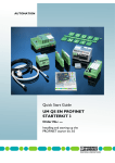
1
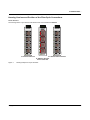
FL SWITCH SFN 6TX/2FX
Ord.-No.: 2891314
US
FL SWITCH SFN ...
K/
LN
T
AC
FL SWITCH SFN 5TX
Ord.-No.: 2891152
K/
LN
T
AC
X1
100
Five and Eight Port Standard Function Ethernet
Switches with Narrow Housings –
Gigabit as an Option
K/
LN
T
AC
X2
100
K/
LN
T
AC
Data Sheet
7267_en_01
X2
100
K/
LN
T
AC
K/
LN
T
AC
X3
X4
100
100
K/
LN
T
AC
K/
LN
T
AC
X5
X6
100
LNK/
T
AC
100
AUTOMATIONWORX
X1
100
100
X3
K/
LN
T
AC
X7
100
100
LNK/
T
AC
X8
K/
LN
T
AC
X4
100
© PHOENIX CONTACT - 02/2007
Description
The FL SWITCH SFN ... range of Factory Line switches with
standard functions in numerous versions can be used for
quick and cost-effective Ethernet network expansion to the
field level. Due to their narrow housing design, the components are suitable for universal remote use in control cabinets and junction boxes. The switches have five or eight
ports, up to two of which are glass fiber ports provided in SC
or ST format. The switches support the auto negotiation
function at the twisted pair ports and offer transmission
speeds of 10/100/1000 Mbps depending on the switch version. Mixed operation for the connection of segments with
different data transmission speeds is also supported. The
glass fiber ports only support 100 Mbps or 1000 Mbps (Gigabit version).
The RJ45 ports offer an auto crossing function, which
means it is not necessary to make a distinction between 1:1
and crossover cables.
The fiber optic ports can be used to extend the segment
length up to 20 km. Unused RJ45 ports can be fitted with
security caps to provide mechanical protection against unauthorized use.
LNK/ACT
100
X5
Features and Fields of Application
–
–
–
Increased network performance
- Switched Ethernet reduces traffic and non predictable
timing
- Quality of Service: Pretagged high priority messages
are forwarded before lower priority messages during
periods of high network traffic loading
- Gigabit options for data intensive applications
Easy network expansion
- No configuration of the switch
- Autonegotiation and autocross simplify cabeling
- Coupling copper network segments with different bit
rates with automatic detection of the data
transmission speed of 10 Mbps, 100 Mbps or
1000 Mbps depending on the switch version.
Fiber optic options extend distance and electrical noise
immunity
- 1 or 2 ports option
- SC or ST connector options
- Multimode or singlemode option
Low cost, low complexity security (optional)
- Connect Layer 1 security elements at the RJ45 port to
restrict access or tampering
- No software setup needed
Please note the different connection directions of the transmission media for five-port switches: copper cables
are connected at the front, glass fiber cables at the bottom.
Make sure you always use the latest documentation.
It can be downloaded at www.download.phoenixcontact.com.
A conversion table is available on the Internet at
www.download.phoenixcontact.com/general/7000_en_00.pdf.
This data sheet is valid for all products listed on the following page:
FL SWITCH SFN ...
Ordering Data
Ethernet Switches with 10/100 Mbps
Description
Type
Order No.
Ethernet switch with 5 RJ45 ports for 10/100 Mbps
FL SWITCH SFN 5TX
2891152
Pcs./Pkt.
1
Ethernet switch with 4 RJ45 ports and
1 fiber optic port in SC format for 10/100 Mbps
FL SWITCH SFN 4TX/FX
2891851
1
Ethernet switch with 4 RJ45 ports and
1 fiber optic port in ST format for 10/100 Mbps
FL SWITCH SFN 4TX/FX ST
2891453
1
Ethernet switch with 8 RJ45 ports for 10/100 Mbps
FL SWITCH SFN 8TX
2891929
1
Ethernet switch with 7 RJ45 ports and
1 fiber optic port in SC format for 10/100 Mbps
FL SWITCH SFN 7TX/FX
2891097
1
Ethernet switch with 7 RJ45 ports and
1 fiber optic port in ST format for 10/100 Mbps
FL SWITCH SFN 7TX/FX ST
2891110
1
Ethernet switch with 6 RJ45 ports and 2 fiber optic ports in SC format
FL SWITCH SFN 6TX/2FX
2891314
1
Ethernet switch with 6 RJ45 ports and
2 fiber optic ports in ST format for 10/100 Mbps
FL SWITCH SFN 6TX/2FX ST
2891411
1
Description
Type
Order No.
Pcs./Pkt.
Ethernet switch with 8 RJ45 ports for 10/100/1000 Mbps
FL SWITCH SFN 8GT
2891673
1
Ethernet switch with 7 RJ45 ports for 10/100/1000 Mbps and 1 fiber optic port
in SC format (multi-mode), 850 nm up to 550 m distance
FL SWITCH SFN 7GT/SX
2891518
1
Ethernet switch with 6 RJ45 ports for 10/100/1000 Mbps and 2 fiber optic
ports in SC format (multi-mode), 850 nm up to 550 m distance
FL SWITCH SFN 6GT/2SX
2891398
1
Ethernet switch with 6 RJ45 ports for 10/100/1000 Mbps and 2 fiber optic
ports in SC format (single mode), 1310 nm up to 10 km distance
FL SWITCH SFN 6GT/2LX
2891987
1
Ethernet switch with 6 RJ45 ports for 10/100/1000 Mbps and 2 fiber optic
ports in SC format (single mode), 1310 nm up to 20 km distance
FL SWITCH SFN 6GT/2LX-20
2891563
1
Accessories
Description
Type
Order No.
Pcs./Pkt
Universal end clamp
E/NS 35 N
0800886
50
Dust protection caps for RJ45 female connectors
FL RJ45 PROTECT CAP
2832991
10
Ethernet Switches with 10/100/1000 Mbps (Gigabit)
Security set for 4 RJ45 ports
FL SEC PAC 4TX
2832865
4
Patch angle with 2 ports in CAT 5e
FL PF 2TX CAT5E
2891165
1
Patch angle with 8 ports in CAT 5e
FL PF 8TX CAT5E
2891178
1
Patch angle with 2 ports in CAT 6
FL PF 2TX CAT6
2891068
1
Patch angle with 8 ports in CAT 6
FL PF 8TX CAT6
2891071
1
1
Patch angle with security elements for 2 ports in CAT 5e
FL PF SEC 2TX
2832687
Patch angle with security elements for 8 ports in CAT 5e
FL PF SEC 8TX
2832690
1
Patchbox 8 x RJ45 CAT 5e, pre-assembled, can be retrofitted
FL PBX 8TX
2832496
1
Patchbox 6 x RJ45 CAT 5e and 4 SC-RJ, glass pre-assembled, can be retrofitted
FL PBX 6TX/4FX
2832506
1
Patch cable, CAT 5, pre-assembled, 0.3 m long
FL CAT5 PATCH 0,3
2832250
10
Patch cable, CAT 5, pre-assembled, 0.5 m long
FL CAT5 PATCH 0,5
2832263
10
Patch cable, CAT 5, pre-assembled, 1.0 m long
FL CAT5 PATCH 1,0
2832276
10
Patch cable, CAT 5, pre-assembled, 1.5 m long
FL CAT5 PATCH 1,5
2832221
10
Patch cable, CAT 5, pre-assembled, 2.0 m long
FL CAT5 PATCH 2,0
2832289
10
Patch cable, CAT 5, pre-assembled, 3.0 m long
FL CAT5 PATCH 3,0
2832292
10
Patch cable, CAT 5, pre-assembled, 5.0 m long
FL CAT5 PATCH 5,0
2832580
10
Patch cable, CAT 5, pre-assembled, 7.5 m long
FL CAT5 PATCH 7,5
2832616
10
Patch cable, CAT 5, pre-assembled, 10.0 m long
FL CAT5 PATCH 10
2832629
10
7267_en_01
PHOENIX CONTACT
2
FL SWITCH SFN ...
Technical Data
General Data
Function
Switch/repeater; conforms to standard IEEE 802.3
Latency of the communication processor
8 µs plus frame time
Housing dimensions (width x height x depth) in mm
5-port switch (RJ45)
30 x 120 x 70 (without COMBICON/without fiber optics)
8-port switch (RJ45)
50 x 120 x 70 (without COMBICON/without fiber optics)
Operating temperature (10/100 Mbit/s switch) and
FL SWITCH SFN 6GT/2LX-20
0°C to 60°C
Operating temperature (10/100/1000 Mbit/s switch),
not FL SWITCH SFN 6GT/2LX-20
-25°C to 60°C
Storage temperature (10/100 Mbit/s switch) and
FL SWITCH SFN 6GT/2LX-20
-20°C to 70°C
Operating temperature (10/100/1000 Mbit/s switch),
not FL SWITCH SFN 6GT/2LX-20
-35°C to 85°C
Degree of protection
IP20, DIN 40050, IEC 60529
Protection class
Class 3 VDE 0106; IEC 60536
Humidity (operation and storage)
10% to 95%, no condensation
Air pressure (operation)
86 kPa to 108 kPa, 1500 m above sea level
Air pressure (storage)
66 kPa to 108 kPa, 3500 m above sea level
Preferred mounting position
Perpendicular to a standard DIN rail
Connection to protective earth ground
Snapped onto a grounded DIN rail
Weight
5-port switch
265 g, approximately
8-port switch
440 g, approximately
Supply Voltage (US)
Connection
Via COMBICON;
conductor cross section = 2.5 mm2, maximum
Nominal value (10/100 Mbit/s switch)
24 V DC
Nominal value (10/100/1000 Mbit/s switch)
12 V DC to 24V DC
Permissible ripple
3.6 Vpp within the permissible voltage range
Permissible voltage range (10/100 Mbit/s switch)
18.5 V DC to 30.2 V DC
Permissible voltage range (10/100/1000 Mbit/s switch)
9 V DC to 30.2 V DC
Inrush current
Depends on the device - see the following table
Test voltage
500 V DC for one minute
Protection against polarity reversal
Present
Current consumption
Depends on the device - see the following table
Current Consumption and Inrush Current
Current Consumption (max)
Power up Inrush Current
FL SWITCH SFN 5TX
2.3 A for 3 ms
90 mA (24 V DC)
FL SWITCH SFN 4TX/FX
140 mA (24 V DC)
2.4 A for 2 ms
FL SWITCH SFN 4TX/FX ST
140 mA (24 V DC)
2.9 A for 2 ms
FL SWITCH SFN 8TX
140 mA (24 V DC)
3.1 A for 2 ms
FL SWITCH SFN 7TX/FX
190 mA (24 V DC)
3.4 A for 2 ms
FL SWITCH SFN 7TX/FX ST
190 mA (24 V DC)
3.4 A for 2 ms
FL SWITCH SFN 6TX/2FX
230 mA (24 V DC)
3.6 A for 2 ms
FL SWITCH SFN 6TX/2FX ST
230 mA (24 V DC)
3.3 A for 2 ms
FL SWITCH SFN 8GT
430 mA (24 V DC) / 1010 mA (9 V DC)
3.1 A for 3 ms
FL SWITCH SFN 7GT/SX
320 mA (24 V DC) / 900 mA (9 V DC)
4.2 A for 3 ms
FL SWITCH SFN 6GT/2SX
350 mA (24 V DC) / 960 mA (9 V DC)
4.4 A for 3 ms
FL SWITCH SFN 6GT/2LX
360 mA (24 V DC) / 950 mA (9 V DC)
4.4 A for 3 ms
FL SWITCH SFN 6GT/2LX-20
360 mA (24 V DC) / 990 mA (9 V DC)
4.4 A for 3 ms
7267_en_01
PHOENIX CONTACT
3
FL SWITCH SFN ...
Interfaces
Total number of Ethernet interfaces
5/8
Mac Address Table Size (Entries)
1 K (4, 5, 8 TX versions), 8 K (all others)
Properties of RJ45 Ports
Number
4, 5, 6, 7 or 8 depending on the device version
Connection format
8-pos. RJ45 female connector on the switch
Connection medium
Twisted pair cable with a conductor cross section of 0.14 mm2 to 0.22 mm2
Cable impedance
100 ohms
Transmission speed
10/100 Mbps or 10/10/1000 Mbps
Maximum network segment expansion
100 m
General Properties of Fiber Optic Ports
Number
0, 1 or 2 depending on the device version
Connection format 100 Mbit/s
SC duplex or ST female connector on the switch
Connection format 1000 Mbit/s
SC duplex connector on the switch
Laser protection
Class 1 according to DIN EN 60825-1:2001-11
Properties of 100 Mbit/s Multimode
Transmission rate
100 Mbit/s Full duplex
Wavelength
1300/1310 nm
Max. transmission length
2 km Fiber optic 50/125
2 km Fiber optic 62.5/125
Transmission power (Medium type) dynamic (average)
Minimum
-23.5 dBm (50/125 µm) / -20 dBm (62.5/125 µm)
Maximum
-14 dBm (50/125 µm) / -14 dBm (62.5/125 µm)
Transmission power (Medium type) static
Minimum
-22.5 dBm (50/125 µm) / -19 dBm (62.5/125 µm)
Maximum
-14 dBm (50/125 µm) / -14 dBm (62.5/125 µm)
Receiver sensitivity
Minimum
-31 dBm (dynamic) / -31 dBm (static)
Maximum
-14 dBm (dynamic) / -14 dBm (static)
Properties of 1000 Mbit/s Multimode
Transmission rate
1.25 Gbit/s Full duplex
Wavelength
850 nm
Max. transmission length
260 m Fiber optic 50/125
550 m Fiber optic 62.5/125
Transmission power
Minimum
-9.5 dBm
Maximum
-4 dBm
Receiver sensitivity
Minimum
-17 dBm
Maximum
-3 dBm
Properties of 1000 Mbit/s Singlemode
Transmission rate
1.25 Gbit/s Full duplex
Wavelength
1310 nm
Max. transmission length FL SWITCH 6GT/2LX
Max. transmission length FL SWITCH 6GT/2LX-20
10 km Fiber optic 9/125
20 km Fiber optic 9/125
Transmission power
Minimum
-10 dBm
Maximum
-3 dBm
Receiver sensitivity
Minimum
-0 dBm
Maximum
-20 dBm
7267_en_01
PHOENIX CONTACT
4
FL SWITCH SFN ...
Interfaces (Continued)
Alarm Contact for Gigabit Version
Voltage
24 V DC, typical
Current carrying capacity
100 mA maximum including inrush
Mechanical Tests
Shock test according to IEC 60068-2-27
Operation: 25g, 11 ms period, half-sine shock pulse
Storage/transport: 50g, 11 ms period, half-sine shock pulse
Vibration resistance according to IEC 60068-2-6
Operation/storage/transport: 5g, 150 Hz, Criterion 3
Free fall according to IEC 60068-2-32
1m
Conformance With EMC Directives
Developed according to IEC 61000-6-2
IEC 61000-4-2 (ESD)
Criterion B
IEC 61000-4-3 (radiated-noise immunity)
Criterion A
IEC 61000-4-4 (burst)
Criterion A
IEC 61000-4-5 (surge)
Criterion B
IEC 61000-4-6 (conducted noise immunity)
Criterion A
IEC 61000-4-8 (noise immunity against magnetic fields)
Criterion A
EN 55022 (noise emission)
Class A
Approvals
10/100 Mbit/s switch
CE, cURUS, ROHS EEE 2002/95/EC, WEEE 2002/96/EC, UL 1604 hazardous locations: Class I, Division 2, Groups A, B, C, D; Temp Code T5;
0C< Tamb < 60C, Installed in minimum IP54 enclosure
10/100/1000 Mbit/s switch
CE, cURUS, ROHS EEE 2002/95/EC, WEEE 2002/96/EC, UL 1604 hazardous locations: In preparation
Differences Compared to Previous Versions
Version 00 - First version
Version 01 - Update Gigabit, supply voltage, current consumption, surge and approvals
7267_en_01
PHOENIX CONTACT
5
FL SWITCH SFN ...
Housing Versions and Position of the Fiber Optic Connections
5 Port Versions
The housings of the 5-port versions are identical. Port 5 is located at the bottom.
FL SWITCH SFN 4TX/FX ST
Ord.-No.: 2891453
FL SWITCH SFN 5TX
Ord.-No.: 2891152
K/
LN
T
AC
X1
X1
100
100
K/
LN
T
AC
K/
LN
T
AC
X2
X2
100
100
K/
LN
T
AC
K/
LN
T
AC
X3
X3
100
100
K/
LN
T
AC
K/
LN
T
AC
X4
X4
100
100
LNK/ACT
100
X5
LNK/ACT
FL SWITCH SFN 5TX
100
X5
LNK/ACT
X5
72671000
K/
LN
T
AC
FL SWITCH SFN 4TX/FX ST
FL SWITCH SFN 5TX
with FL SEC PAC
Figure 1
7267_en_01
Housing example for 5-port switches
PHOENIX CONTACT
6
FL SWITCH SFN ...
8 Port Versions
The housings of the 8-port versions are identical. On the fiber optic versions, the connections for the fiber optic ports are at
the front. The physical location of the ports on the 10/100 and 10/100/1000 (Gigabit) switches are the same.
FL SWITCH SFN 8GT
Ord.No.2891673
Link 10
Act 10
1
US
FL SWITCH SFN 8TX
Ord.No.2891929
US
FL SWITCH SFN 6TX/2FX
Ord.No.2891314
US
/
100
T
AC
/
100
T
AC
X1
X2
0/
100
T
AC
0/
100
T
AC
/
100
T
AC
K/
LN
T
AC
K/
LN
T
AC
K/
LN
T
AC
K/
LN
T
AC
K/
LN
T
AC
K/
LN
T
AC
X2
X1
X2
X1
X2
100
100
100
100
100
/
100
T
AC
K/
LN
T
AC
K/
LN
T
AC
K/
LN
T
AC
K/
LN
T
AC
K/
LN
T
AC
K/
LN
T
AC
X3
X4
X3
X4
X3
X4
X3
X4
100
100
100
100
100
100
0/
100
T
AC
0/
100
T
AC
/
100
T
AC
/
100
T
AC
K/
LN
T
AC
K/
LN
T
AC
K/
LN
T
AC
K/
LN
T
AC
K/
LN
T
AC
K/
LN
T
AC
X5
X6
X5
X6
X5
X6
X5
X6
100
100
100
100
100
100
0/
100
T
AC
0/
100
T
AC
/
100
T
AC
/
100
T
AC
K/
LN
T
AC
K/
LN
T
AC
100 /
K
LN
T
AC
100 /
K
LN
T
AC
K/
LN
T
AC
100 /
K
LN
T
AC
X7
X8
X7
X8
X7
X8
X7
X8
100
100
0/
100
T
AC
0/
100
T
AC
100
72671001
X1
100
FL SWITCH SFN 6TX/2FX
FL SWITCH SFN 8GT
FL SWITCH SFN 8TX
with FL SEC PAC
Figure 2
FL SWITCH SFN 7TX/FX
Ord.No.2891097
US
2
US
FL SWITCH SFN 7TX/FX
Housing example for 8-port switches
Local Diagnostic and Status Indicators for 10/100 or 10/100/1000 Mbps Versions
Des.
Color
Status
US
or
US1/2
Green
ON
Supply voltage US in the tolerance range
Meaning
OFF
Supply voltage US too low
LEDs on 10/100 Mbps Versions for the Data Transmission Speed (2 LEDs/Port)
10 Mbps
100 Mbps
LNK/ACT
ON/blinking
ON/blinking
100
OFF
ON
LNK/ACT LED:
ON: indicates an electrical Link
Blinking: indicates network traffic (at high data rates the blinking is in a constant rate)
7267_en_01
PHOENIX CONTACT
7
FL SWITCH SFN ...
LEDs on 10/100/1000 Mbps Versions for the Data Transmission Speed (2 LEDs/Port)
10 Mbps
100 Mbps
1000 Mbps
100/ACT
ON/blinking
ON/blinking
OFF
1000/ACT
ON/blinking
OFF
ON/blinking
One LED/port ON or blinking:
ON: indicates an electrical Link
Blinking: indicates network traffic at the data rate (x Mbit/s)
Both LEDs/port ON or blinking:
Both ON: indicates a 10 Mbit/s electrical Link
Both Blinking: indicates 10 Mbit/s network traffic
General Information
Warning
Disregarding this warning may result in damage to equipment and/or serious personal injury. Only qualified personnel may start up and operate these devices. According to the safety instructions in this text, qualified personnel are persons who are authorized to start up, to ground, and to mark devices, systems, and equipment
according to the standards of safety technology. In addition, these persons must be familiar with all warning
instructions and maintenance measures in this text.
Warning
The FL SWITCH SFN ... module is designed exclusively for SELV operation according to
IEC 950/EN 60950/VDE 0805.
Using the FL SEC PAC Kit for Port Security
Layer 1 Port security for up to 4 ports, is provided by purchasing the FL SEC PAC kit. The kit contains 4 red security frames,
4 grey port blocking security caps, unlocking key and instructions. The red security frame must first be attached to each
port that is to be secured.
– First orient the red security frame, so that the cable
– Then, insert the 4 mounting feet of the security frame
locking tabs of both the frame and the switch are
into the pre-punched holes around the switch port and
aligned.
push until the frame snaps into place with an audible
click.
Once attached, the security frames are permanently mounted and can not be removed.
Inserted cables or grey port blocking security caps will now be locked into place. Instructions for using the key to unlock the
cables or security caps are included in the kit.
7267_en_01
PHOENIX CONTACT
8
FL SWITCH SFN ...
Installation and Assembly/Removal
Install the FL SWITCH SFN ... on a clean DIN rail. To avoid contact resistance only use clean, corrosion-free DIN rails. End
clamps can be mounted on both sides of the module to stop the modules from slipping on the DIN rail.
Connect the DIN rail to protective earth ground using a grounding terminal block. The modules are grounded
when they are snapped onto the DIN rail. Connect protective earth ground with low impedance. Gigabit components have a functional earth ground connecting screw on the top.
Assembly:
1.
2.
3.
Once the module has been snapped on properly,
check that it is fixed securely on the DIN rail.
3.
Lift the module from the DIN rail.
Place the module onto the DIN rail from above. The upper holding keyway must be hooked onto the top edge
of the DIN rail.
Push the module from the front towards the mounting
surface.
Removal:
1.
2.
Insert a suitable tool (e.g., needle-nose pliers) into the
arresting latch and pull it down.
Pull the module slightly away from the mounting surface.
Terminal Assignment for 10/100 Mbps Versions
US
GND
Terminal
1
2
3
4
Meaning
Supply voltage +US
GND US
Functional earth ground
Functional earth ground
Terminal
1
2
3
4
5
6
Meaning
Supply voltage +US 1
GND US 1
Supply voltage +US 2
GND US 2
Alarm contact R1
Alarm contact R2
1 2 3 4
Figure 3
Terminal assignment
Terminal Assignment for 10/100/1000 Mbps Versions
US1 GND US2 GND R1
R2
1 2 3 4 5 6
Figure 4
7267_en_01
Terminal assignment
PHOENIX CONTACT
9
FL SWITCH SFN ...
Supply Voltage Connection and Grounding for 10/100 Mbps Versions
Supply Voltage
+ -
The switch is designed for SELV operation at +24 V DC according to IEC 950/EN 60950/VDE 0805. Only SELV according to the defined standards may be used for supply
purposes.
24 V DC
Connection to Functional Earth Ground
Snapping the switch onto a grounded DIN rail connects it to
the ground potential. In an environment particularly prone
to EMI, noise immunity can be increased by an additional
low-impedance connection to functional earth ground via
terminal 3 or 4.
US
GND
1 2 3 4
Figure 5
Example for supply of a 10/100 Mbps module
Supply Voltage Connection and Grounding for 10/100/1000 Mbps Versions
Supply Voltage
The switch is designed for SELV operation at 24 V DC according to IEC 950/EN 60950/VDE 0805. Only SELV according
to the defined standards may be used for supply purposes.
Operate the module using a +24 V DC SELV. The module is fully operational even with only one supply voltage
(without jumpering it to other supply voltage terminal blocks) and/or without wiring the alarm contact
(see Figure 6, A).
A
B
24 V DC
US1 GND US2 GND R1
24 V DC
+ -
R2
1 2 3 4 5 6
+ -
US1 GND US2 GND R1
R2
1 2 3 4 5 6
72670008
Figure 6
Supply of a 10/100/1000 Mbps module from one or two voltage sources
Alarm Contact Operation
–
–
One or more power supplies failed -> the contact closes
Power OK -> the contact opens
The maximum current, include inrush, is 100 mA.
7267_en_01
PHOENIX CONTACT
10
FL SWITCH SFN ...
Connection to Functional Earth Ground
Snapping the switch onto a grounded DIN rail connects it to
the ground potential. In an environment particularly prone
to EMI, the switch can be grounded by an additional low-im-
pedance connection to functional earth ground via an eyelet ring on the upper part of the housing.
FL SWITCH SFN 6GT/2SX
Ord.-No.: 2891398
US
K/
LN
T
AC
X1
100
K/
LN
T
AC
X2
K/
LN
T
AC
X3
100
100
K/
LN
T
AC
X4
K/
LN
T
AC
K/
LN 100
T
AC
X5
X6
100
100
K/
LN
T
AC
K/
LN
T
AC
X7
X8
100
100
72670009
Figure 7
Grounding via an eyelet ring
Ethernet Interface
The FL SWITCH SFN ... has up to 8 Ethernet ports on the front in RJ45 format, to which only twisted pair cables with an
impedance of 100 Ω can be connected. The data transmission speed is 10 Mbps/100 Mbps or
10 Mbps/100 Mbps/1000 Mbps. In addition, every port has an auto crossing function: it is not necessary to make a distinction between 1:1 or crossover Ethernet cables.
10/100 Mbps
10/100/1000 Mbps
RJ45
RJ45
8 7 6 5
4 3 2 1
n.c. TDn.c. RDn.c. n.c.
TD+ RD+
Figure 8
7267_en_01
8 7 6 5
4 3 2 1
DD- DBDC+ DADD+ DCDB+ DA+
Pin assignment of the Ethernet ports in RJ45 format
PHOENIX CONTACT
11
FL SWITCH SFN ...
Switching Characteristics of the FL SWITCH SFN ...
–
–
Store and Forward
All data telegrams that are received by the switch are
saved and their validity checked. Invalid or faulty data
packets (> 1522 bytes or CRC errors) and fragments
(< 64 bytes) are rejected. Valid data telegrams are forwarded by the switch. The switch always forwards the
data using the data transmission speed that is used in
the destination network segment.
Multi-Address Function
The switch independently learns the addresses for termination devices, which are connected via a port, by
evaluating the source addresses in the data telegrams.
Only packets with unknown addresses, with a source
address of this port or with a multicast/broadcast address in the destination address field are forwarded via
–
the corresponding port. The switch can store addresses in its address table with an aging time of 5 minutes.
This is important when more than one termination device is connected to one or more ports. In this way, several independent subnetworks can be connected to
one switch.
Quality of Service (QoS): IEEE 802.1P/Q
The SFN switches are capable of reading Ethernet
packets that have already been assignent a priority level by a managed switch or other. In cases of heavy traffic, packets with a priority 4-7 are considered high
priority and processed before packets with 0-3 priority
level. After prioritization the packets are forwarded
without modification.
A restart deletes the entire address table.
Housing Dimensions
14 mm
FL SWITCH SFN 8TX
Ord.-No.: 2891929
US
FL SWITCH SFN 5TX
Ord.-No.: 2891152
K/
LN
T
AC
K/
LN
T
AC
K/
LN
T
AC
X1
X1
X2
100
100
100
K/
LN
T
AC
K/
LN
T
AC
K/
LN
T
AC
X2
X3
X4
100
100
100
K/
LN
T
AC
K/
LN
T
AC
K/
LN
T
AC
X3
X5
X6
100
100
100
K/
LN
T
AC
K/
LN
T
AC
K/
LN
T
AC
X4
X7
X8
100
100
100
LNK/ACT
100
X5
30 mm
Figure 9
72671004
120 mm
50 mm
Housing dimensions for the FL SWITCH SFN ...
The housing depth is 70 mm for all housing versions.
© PHOENIX CONTACT 02/2007
7267_en_01
PHOENIX CONTACT GmbH & Co. KG • 32823 Blomberg • Germany
Phone: +49-(0) 5235-3-00 • Fax: +49-(0) 5235-3-4 12 00
www.phoenixcontact.com
12