1
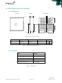
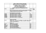
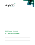
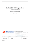
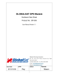
SPIDER’S ANTENNAS (ORG18-4T GNSS)
ANTENNA ELEMENT
Datasheet
OriginGPS.com
ORG18-4T GNSS Antenna Datasheet
Revision 3.0
Page 1 of 8
March 15, 2015
INDEX
1.
2.
3.
4.
5.
6.
7.
8.
9.
10.
11.
12.
12.1.
12.2.
13.
13.1.
13.2.
14.
15.
16.
17.
SCOPE ................................................................................................................................................................... 3
DISCLAIMER .......................................................................................................................................................... 3
SAFETY INFORMATION ......................................................................................................................................... 3
ESD SENSITIVITY .................................................................................................................................................... 3
CONTACT INFORMATION...................................................................................................................................... 3
RELATED DOCUMENTATION ................................................................................................................................. 3
REVISION HISTORY ................................................................................................................................................ 3
GLOSSARY ............................................................................................................................................................. 4
ABOUT SPIDER FAMILY ......................................................................................................................................... 5
ABOUT SPIDER'S ANTENNAS................................................................................................................................. 5
ABOUT ORIGINGPS ............................................................................................................................................... 5
SPECIFICATIONS .................................................................................................................................................... 6
ELECTRICAL CHARACTERISTICS ............................................................................................................................. 6
TYPICAL S11 .......................................................................................................................................................... 6
MECHANICAL SPECIFICATIONS ............................................................................................................................. 7
DIMENSIONS ......................................................................................................................................................... 7
MATERIALS............................................................................................................................................................ 7
SOLDERING CONDITION........................................................................................................................................ 8
STORAGE ............................................................................................................................................................... 8
COMPLIANCE ........................................................................................................................................................ 8
RELIABILITY ........................................................................................................................................................... 8
TABLE INDEX
TABLE 1 – RELATED DOCUMENTATION ................................................................................................................................ 3
TABLE 2 – REVISION HISTORY ............................................................................................................................................... 4
TABLE 3 – .............................................................................................................................................................................. 6
TABLE 4 – MECHANICAL INFORMATION ............................................................................................................................... 7
TABLE 5 – MATERIALS ........................................................................................................................................................... 7
TABLE 6 – RELIABILITY DATA ................................................................................................................................................. 8
FIGURE INDEX
FIGURE 1 – S11 SMITH CHART .............................................................................................................................................. 6
FIGURE 2 – MECHANICAL OUTLINE ...................................................................................................................................... 7
1. SCOPE
This document describes the features and specifications of Spider’s Antennas ORG18-4T GNSS Antenna.
2. DISCLAIMER
All trademarks are properties of their respective owners.
Performance characteristics listed in this document do not constitute a warranty or guarantee of product
performance. OriginGPS assumes no liability or responsibility for any claims or damages arising out of the
use of this document, or from the use of integrated circuits based on this document.
OriginGPS assumes no liability or responsibility for unintentional inaccuracies or omissions in this document.
OriginGPS reserves the right to make changes in its products, specifications and other information at any
time without notice.
OriginGPS reserves the right to conduct, from time to time, and at its sole discretion, firmware upgrades.
As long as those FW improvements have no material change on end customers, PCN may not be issued.
OriginGPS navigation products are not recommended to use in life saving or life sustaining applications.
ORG18-4T GNSS Antenna Datasheet
Revision 4.0
Page 2 of 9
March 15, 2015
3. SAFETY INFORMATION
Improper handling and use can cause permanent damage to the product.
4. ESD SENSITIVITY
This product is ESD sensitive device and must be handled with care.
5. CONTACT INFORMATION
Support - [email protected] or Online Form
Marketing and sales - [email protected]
Web – www.origingps.com
6. RELATED DOCUMENTATION
№
DOCUMENT NAME
1
Micro Spider – ORG4475 Evaluation Kit Datasheet
2
Micro Spider – ORG4475 Product Change Notification
3
Spider and Hornet - Software User Manual for CSR® based receivers
4
Spider and Hornet - NMEA Protocol Reference Manual for CSR® based receivers
5
Spider and Hornet - One Socket Protocol Reference Manual for CSR® based receivers
6
Spider and Hornet - Host Interface Application Note
7
Spider and Hornet - Low Power Modes Application Note
8
Spider and Hornet - Jammer Detector and Remover Application Note
9
Spider and Hornet - Client Generated Extended Ephemeris Application Note
10
Spider and Hornet - Server Generated Extended Ephemeris Application Note
11
Spider and Hornet - Ephemeris Push Application Note
TABLE 1 – RELATED DOCUMENTATION
7. REVISION HISTORY
REVISION
DATE
CHANGE DESCRIPTION
A00
December 1, 2011
First release
2.0
January 14, 2015
Format update
3.0
March 15, 2015
Updated GNSS Support
4.0
August 10, 2015
Updated GNSS data and S11
TABLE 2 – REVISION HISTORY
ORG18-4T GNSS Antenna Datasheet
Revision 4.0
Page 3 of 9
March 15, 2015
8. GLOSSARY
A-GNSS Assisted GNSS
BPF Band Pass Filter
CE European Community conformity mark
CGEE™ Client Generated Extended Ephemeris
CMOS Complementary Metal-Oxide Semiconductor
COMPASS PRC GNSS (same as BDS BeiDou-2 Navigation Satellite System)
EGNOS European Geostationary Navigation Overlay Service
EMC Electro-Magnetic Compatibility
ESD Electro-Static Discharge
EVB Evaluation Board
EVK Evaluation Kit
FCC Federal Communications Commission
GALILEO EU GNSS
GLONASS Global Navigation Satellite System
GNSS Global Navigation Satellite System
GPS Global Positioning System
I²C Inter-Integrated Circuit
IC Integrated Circuit
ISO International Organization for Standardization
LDO Low Dropout regulator
LGA Land Grid Array
LNA Low Noise Amplifier
MSAS Multi-functional Satellite Augmentation System
MSL Moisture Sensitivity Level
NFZ™ Noise-Free Zones System
NMEA National Marine Electronics Association
MEMS MicroElectroMechanical Systems
PCB Printed Circuit Board
PPS Pulse Per Second
QZSS Quasi-Zenith Satellite System
REACH Registration, Evaluation, Authorisation and Restriction of Chemical substances
RF Radio Frequiency
RHCP Right-Hand Circular Polarized
RoHS Restriction of Hazardous Substances directive
ROM Read-Only Memory
RTC Real-Time Clock
SAW Surface Acoustic Wave
SBAS Satellite-Based Augmentation Systems
SGEE™ Server Generated Extended Ephemeris
SIP System In Package
SMD Surface Mounted Device
SMT Surface-Mount Technology
SOC System On Chip
SPI Serial Peripheral Interface
TCXO Temperature-Compensated Crystal Oscillator
TTFF Time To First Fix
TTL Transistor-Transistor Logic
UART Universal Asynchronous Receiver/Transmitter
WAAS Wide Area Augmentation System
ORG18-4T GNSS Antenna Datasheet
Revision 4.0
Page 4 of 9
March 15, 2015
9. ABOUT SPIDER FAMILY
OriginGPS GNSS receiver modules have been designed to address markets where size, weight, stand-alone
operation, highest level of integration, power consumption and design flexibility - all are very important.
OriginGPS’ Spider family breaks size barrier, offering the industry’s smallest fully-integrated, highly-sensitive
GPS and GNSS modules.
Spider family features OriginGPS' proprietary NFZ™ technology for high sensitivity and noise immunity even
under marginal signal condition, commonly found in urban canyons, under dense foliage or when the
receiver’s position in space rapidly changes.
Spider family enables the shortest TTM (Time-To-Market) with minimal design risks.
Just connect an antenna and power supply on a 2-layer PCB.
10. ABOUT SPIDER'S ANTENNAS
L1 Ceramic Patch Antennas – For ultimate compatibility and best-in-class performance use our Spider’s
modules together with Spider’s Antennas.
11. ABOUT ORIGINGPS
OriginGPS is a world leading designer, manufacturer and supplier of miniature positioning modules, antenna
modules and antenna solutions.
OriginGPS modules introduce unparalleled sensitivity and noise immunity by incorporating Noise Free Zone
system (NFZ™) proprietary technology for faster position fix and navigation stability even under challenging
satellite signal conditions.
Founded in 2006, OriginGPS is specializing in development of unique technologies that miniaturize RF
Modules, thereby addressing the market need for smaller wireless solutions.
ORG18-4T GNSS Antenna Datasheet
Revision 4.0
Page 5 of 9
March 15, 2015
12. SPECIFICATIONS
12.1. ELECTRICAL CHARACTERISTICS
Parameter
Value
Frequency
1575.42-1612
Unit
Notes
MHz
18mm x 18mm GP
Return Loss (S11)
10 (min)
dB
@fC
Bandwidth (BW)
11 (min)
MHz
@ f(S11=-9dB)
VSWR
1.5 (max)
Impedance (ZA)
50
Ω
Axial Ratio (AR)
GPS- Typ. 18.5
GLO- Typ. 15
dB
GPS- Typ. -3.5
GLO- Typ. -4
dBic
18mm x 18mm GP
ppm/°C
-40°C to +85°C
Gain @ fC
@ zenith
Polarization
R.H.C.P
Temperature Factor (tF)
0±20
TABLE 3 – ELECTRICAL CHARACTERISTICS
ORG18-4T GNSS Antenna Datasheet
Revision 4.0
Page 6 of 9
March 15, 2015
12.2. TYPICAL S11
FIGURE 1 – S11 SMITH CHART
Note: Measured on 18x18mm FR4 based ground plane with adhesive tape
ORG18-4T GNSS Antenna Datasheet
Revision 4.0
Page 7 of 9
March 15, 2015
13. MECHANICAL SPECIFICATIONS
13.1. DIMENSIONS
SIDE VIEW
TOP VIEW
BOTTOM VIEW
4.0±0.2
C 1.5
1.10
Ø3.00
18.0±0.2
Ø5.00
Max 0.8
2.8±0.3
18.0±0.2
Adhesive tape
All dimensions are in mm
FIGURE 2 – MECHANICAL OUTLINE
Dimensions
Length
Width
Thickness
Weight
mm
18.0 ± 0.2
18.0 ± 0.2
4.0 ± 0.2
gr
7.6
inch
0.709 ± 0.008
0.709 ± 0.008
0.157 ± 0.008
oz
0.32
TABLE 4 – MECHANICAL INFORMATION
13.2. MATERIALS
Item
Material
Electrode (Top and Bottom)
Silver
Probe
Silver Plated Brass
Probe pin solder material
Stannum
Dielectric constant
Adhesive tape thickness
0.125mm (typ.)
TABLE 5 – MATERIALS
ORG18-4T GNSS Antenna Datasheet
Revision 4.0
Page 8 of 9
March 15, 2015
14. SOLDERING CONDITION
Compatibility to IEC 68-2-58: ≥ 75% (after aging)
Manual iron soldering (Solder Sn/Ag/Cu 96.5/3.0/0.5)
Note: Soldering conditions must comply to prevent degradation of antenna performance.
15. STORAGE
Electrode metallization is unprotected silver and will tarnish after opening.
Elevated temperature and humidity will accelerate tarnishing process.
Typical floor life should not exceed 6 months after package has been opened.
Bulk antennas older than 6 months should be tested for solder ability before use.
Avoid intentional shock or drop to prevent cracking of antenna.
16. COMPLIANCE
Antennas are designed and being manufactured and handled to comply with and according to
Pb-Free/RoHS Directive 2002/95/EC on the restriction of the use of certain hazardous substances
in electrical and electronic equipment.
Antennas are manufactured in ISO 9001:2000 accredited facilities.
Antennas are manufactured in ISO 14001:2004 accredited facilities.
17. RELIABILITY
Parameter
Description
Pass Criteria
Drop Test
Place antenna on set 1.5m height
Drop 5 times
1. No visible damage
2. S11 is acceptable (Δfc < 0.2%)
Vibration Test
Sine sweep 5Hz – 55Hz – 5Hz, 1 octave/min
Amplitude = 1.5mm
Acceleration = 2g
Crossover frequency = 18Hz
Hold time = 2hr.
1. No visible damage
2. S11 is acceptable (Δfc < 0.2%)
Humidity
60°C, 95% RH, 96hr.
1. No visible damage
2. S11 is acceptable (Δfc < 0.2%)
Thermal Shock
+80°C (30 min) → 5 min → -40°C (30 min)
10 cycles
1. No visible damage
2. S11 is acceptable (Δfc < 0.2%)
High Temperature Resistance
+90°C, 96hr.
1. No visible damage
2. S11 is acceptable (Δfc < 0.2%)
Low Temperature Resistance
- 40°C, 96hr.
1. No visible damage
2. S11 is acceptable (Δfc < 0.2%)
Adhesion Strength of Soldering
Use of pull-push gauge
Spec (min. 5kgf)
IEC Climatic Category (IEC88-1)
-40°C / +90°C / 56hr.
TABLE 6 – RELIABILITY DATA
Notes:
Sample must satisfy the requirement after 24 hours of test
Based on IEC climatic category (IEC68-1) -40°C / +85°C / 56hr.
ORG18-4T GNSS Antenna Datasheet
Revision 4.0
Page 9 of 9
March 15, 2015