1
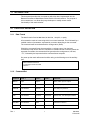
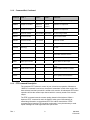
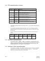
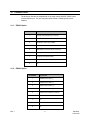
Auxiliary Control Interface Protocol Definition
for VideoBlox Rev. III
User Manual
900.0401 - June 2005 - Rev. 1
ISSUE
DATE
1
June 2005
Rev. 1
REVISIONS
Initial Release
ii
900.0401
17-June-05
LIST OF ABBREVIATIONS
Rev. 1
LED
Light Emitting Diode – i.e. status indication
MVT
Multi-channel Video Titling unit
PCK
Programmable Control Keyboard
PTZ
Pan/Tilt/Zoom equipped camera
iii
900.0401
17-June-05
TABLE OF CONTENTS
1.1 INTRODUCTION.................................................................................................................................. 1
2.1 PROTOCOL DEFINITION .................................................................................................................... 1
2.1.1 Data Format ..................................................................................................................... 1
2.1.2 Command Set .................................................................................................................. 1
2.1.3 PTZ Command Description ............................................................................................. 2
2.1.4 Read Status Command Description ................................................................................ 3
2.1.5 Read Alarms / Videos Command Description ................................................................. 3
3.1 CONNECTIONS .................................................................................................................................. 4
3.1.1 RS232 Option................................................................................................................... 4
3.1.2 RS422 Option................................................................................................................... 4
4.1 EXAMPLES.......................................................................................................................................... 5
Rev. 1
iv
900.0401
17-June-05
1.1 INTRODUCTION
This document describes the command set which has been implemented into the
Betatech Surveillance Mate Master Series Revision III matrix switcher. The purpose of
this command set, is to allow third party developers to readily access certain
functionality of the matrix switcher.
2.1 PROTOCOL DEFINITION
2.1.1
Data Format
The data format is fixed at 9600 baud, 8 data bits, 1 stop bit, no parity.
All commands consist of a text string which is not case insensitive. This is followed by a
variable number of parameters, separated by commas, depending on the command.
The command must be terminated with a carriage return (0x0D).
Should the command format be acceptable, a carriage return, line feed and
command prompt will be returned. Should the command format not exactly match the
expected commands, the command will be ignored and a carriage return, line feed,
“???”, followed by the response had the command been accepted.
On power up the matrix will transmit a similar string to the following out of the auxiliary
port:
Betatech SoftCPU Revision
3.17a All rights reserved 1998
SoftCPU>
2.1.2
Command Set
Command
Parm 1
Parm 2
SWITCH
Input
Output
Switch video input to output
PTZRCL
PTZ Address
Position
Recall PTZ pre-positions
PTZSTOR
PTZ Address
Position
Store PTZ pre-positions
PTZAUX
PTZ Address
Aux number
State
Set / Clear PTZ Auxiliary outputs
PTZC
PTZ Address
Function
Parameter
Operate PTZ, see description below
PTZ
Function
Parameter
Operate PTZ, see description below
KBALARM
PCK Address
State
PCK alarm indication
KBLED
PCK Address
LED number
Rev. 1
Parm 3
State
1
Comments
PCK LED indications
900.0401
17-June-05
2.1.2
Command Set, Continued
Command
Parm 1
Parm 2
Parm 3
Comments
KBTEXT
PCK Address
ASCII text
RUNSEQ
Sequence number
Sequence
parameter
STOPSEQ
Sequence number
DISPLAY
Channel number
CLRSCR
Channel number
CLRLINE
Channel number
OUTPUT
System output number State
Operation of system outputs
SETDATE
dd/mm/yy
Set date
SETTIME
hh/mm/ss
Set time
Put text string on PCK display
Default
monitor
Operation of sequences
Operation of sequences
Line number
Text string
Put text string on MVT
Clear screen on MVT
Line number
Clear line on MVT
REV
Read matrix software revision
ALARM?
Alarm number
Return status of alarm input
VIDEO?
Video input number
Return status of video input
MATRIX?
Video output number
ALARMS?
Read all alarm inputs
Return input channel routed to this
output
Return number & status of alarms
VIDEOS?
Return number & status of video
SIZING?
Return system size information
HELP
Display a list of available commands
2.1.3
PTZ Command Description
The command “PTZ” allows for control of pan / tilt and zoom operation. Whenever a
“SWITCH” command is carried out, the system “remembers” which video monitor has
been selected, and the input which is routed to this monitor. All subsequent PTZ control
operation will use the camera input channel which is currently routed to this monitor
output.
The PTZC command uses the camera number instead of the keyboard. When a
keyboard “PTZ” command is used, the SoftCPU takes care of automatically retransmitting information to the selected PTZ. This is NOT done with the “PTZC”
command and to keep the PTZ operating continuously, it may be necessary to send
repeat messages at a rate higher than once per second.
Rev. 1
2
900.0401
17-June-05
2.1.3
PTZ Command Description, Continued
Parm 1
Parm 2
Comments
0
Don’t care
1
Speed
Set Pan speed (right for speed > 0)
2
Speed
Set Tilt speed (up for speed > 0)
3
Direction
Set zoom (zoom in for direction > 0)
4
Direction
Set focus (focus near for direction > 0)
5
Direction
Set Iris (iris open for direction > 0)
6
Lens
Stop pan and tilt operation (no change to lens drive)
Lens packed as described below (only for PTZC)
The “Speed” parameter must be in the range –127 to + 127. A value of 0 stops the pan
or tilt drive.
The “Direction” parameter must be in the range –127 to +127. Currently only fixed
speed commands are implemented, so only the sign is relevant. A value of zero stops
the lens drive.
For the “packed” lens control function, the functions of the lens control byte are as
follows:
2.1.4
Bit 5
Bit 4
Bit 3
Bit 2
Bit 1
Bit 0
Iris Close
Iris Open
Zoom Out
Zoom In
Focus Far
Focus
Near
Read Status Command Description
The commands “REV”, “ALARM?”, “VIDEO”, and “MATRIX?” all request data from the
matrix. In all cases a carriage return, line feed, followed by the requested information,
another carriage return, line feed and the command prompt will be returned. If the
requested parameter is out of range a “0” will be returned.
2.1.5
Read Alarms / Videos Command Description
The commands “ALARMS?” and “VIDEOS?” return the number of channels configured,
followed by cr/lf and a block of data representing the status, a ‘^’ and then the
exclusive-or checksum of the video / alarm status.
Rev. 1
3
900.0401
17-June-05
3.1 CONNECTIONS
The third party interface is implemented on the video matrix SoftCPU “COM4” serial
communications port. This port may have either RS232 or RS422 option boards
installed.
3.1.1
RS232 Option
Pin Number
3.1.2
Pin Function
1
Internally Connected to pins 4 and 6
2
RXD (data from slave device TXD)
3
TXD (data to slave device RXD)
4
Internally Connected to pins 1 and 6
5
GND (RS232 Communications common)
6
Internally Connected to pins 1 and 4
7
CTS (from slave device RTS)
8
RTS (to slave device CTS)
9
N/C
RS422 Option
Pin Number
Rev. 1
Pin Function
1
RS422 Receive data [-]
2
RS422 Receive data [+]
3
RS422 Transmit data [+]
4
RS422 Transmit data [-]
5
RS422 Communications common
6
N/C
7
N/C
8
N/C
9
N/C
4
900.0401
17-June-05
4.1 EXAMPLES
Note that in the following examples “\r”, denotes a carriage return representing 0x0D.
Example 1: Switch video matrix input 15 to video output 7:
SWITCH 15,7\r
Example 2: Cause the PTZ camera connected to input 15 to move to preset position 1:
PTZRCL 15,1 \r
Example 3: Store the current position of the PTZ camera connected to input 12 as
preset position 5:
PTZSTOR 12,5\r
Example 4: Operate the pan function of the PTZ camera routed to output 7 (because
of example 1, this is the currently “active” monitor, which currently has PTZ camera 15
routed to it). The PTZ will move at full speed to the left.
PTZ 1,-127\r
Example 5: Display the text string “Hello World” on line 5 on the titler connected to
video input 15.
DISPLAY 15,5,Hello World\r
Example 6: Turn off system output 1:
OUTPUT 1,0\r
Example 7: Start sequence 5. The parameter which is passed to the sequence is 100
and the default monitor for the sequence is 1.
RUNSEQ 5,100,1\r
Example 8: Stop the above sequence.
STOPSEQ 5\r
Example 9: Set the system date and time to 3:22 pm on 15 January 1998:
DATE 15/01/98\r
TIME 15:22:00\r
Rev. 1
5
900.0401
17-June-05
Example 10: Read the software revision in the matrix.
REV\r
The matrix switcher will return something like:
\n\r
3.17a
\n\r
SoftCPU>
Example 11: Read the current alarm status for alarm input 200.
ALARM? 200\r
The matrix switcher will return something like:
\n\r
1
\n\r SoftCPU>
The “1” indicates that this alarm contact is closed
Example 12: Read the video input status for input 321.
VIDEO? 321\r
The matrix switcher will return something like:
\n\r
1
\n\r
SoftCPU>
The “1” indicates that video is present on this input.
Example 13: Read alarm status.
ALARMS?
The matrix switcher will return something like:
\n\r
32\n\r
01000000^01 \n\r
The 32 is the number of alarms configured. Note that the length of the reply packet will
vary dependant on the configuration. The first two bytes of the alarm status “01”, show
that only alarm input 1 is active. “02” would be alarm 2 active, “03” both alarm 1 and 2.
The block of data is similar to a hexadecimal dump of the alarm status. The “^”
character indicates the end of data and the fact that the checksum will follow. The
last 2 bytes are the exclusive-or checksum of the data portion of the reply.
Rev. 1
6
900.0401
17-June-05
Example 14: Read system sizing.
SIZING?
The matrix switcher will return something like:
\n\r
128 Cameras\n\r
032 Monitors\n\r
128 Alarms\n\r
Rev. 1
7
900.0401
17-June-05
Honeywell Video Systems (Head Office)
2700 Blankenbaker Pkwy, Suite 150
Louisville, KY 40299
www.honeywellvideo.com
TEL+1-800-796–2288
Honeywell Security Australia Pty Ltd.
Unit 5, Riverside Centre, 24-28 River Road West
Parramatta, NSW 2150, Australia
www.ademco.com.au
TEL +61-2-8837-9300
Honeywell Video Systems UK Ltd.
Aston Fields Road, Whitehouse Ind Est
Runcorn, Cheshire, WA7 3DL, UK
www.security.honeywell.com
TEL +44-1928-754-000
Honeywell Security Asia Pacific
Flat A, 16/F, CDW Building, 388 Castle Peak Road
Tsuen Wan, N.T., Hong Kong
www.security.honeywell.com/hk
TEL +852-2405-2323
Honeywell Security South Africa
Unit 6 Galaxy Park, Galaxy Avenue, Linbro
Business Park
P.O. Box 59904, Kengray, 2100, South Africa
www.honeywell.co.za
TEL +27-11-574-2500
Honeywell Security France
Parc Gutenberg, 13, Voie La Cardon
91120, Palaiseau, France
www.ademco.fr
TEL +33-1-6932-1090
Honeywell Security Germany
Großenbaumer Weg 8
40472 Düsseldorf, Germany
www.honeywell-security.de
TEL +49-211-415-090
Honeywell Security Italia SpA
Via della Resistenza 53/59, 20090 Buccinasco
Milan, Italy
www.ademco.it
TEL +39-02-457-1791
Honeywell Security Poland
Chmielewskiego 22a, 70-028
Szczecin, Polska
www.ultrak.pl
TEL +48-91-485-40-60
Honeywell Security Espana
Calle Vivero, 5, 28040
Madrid, Spain
www.ademco.es
TEL +34-91-533-4706
Honeywell Security Czech Republic
Havránkova 33, Brno
Dolní Heršpice, 619 00, Czech Republic
www.olympo.cz
TEL +420-543-558-111
Honeywell Security House (Netherlands)
Amperestraat 41
1446 TR Purmerend, Netherlands
www.SecurityHouse.nl
TEL +31-299-419-000
Honeywell Security Slovakia Republic
Vajnorskà 142, 83104 Bratislava
Slovakia
www.olympo.sk
TEL +421-2-444-54-660
Video Systems
www.honeywellvideo.com
1-800-796-CCTV (North America only)
© 2005 Honeywell International Inc.
All rights reserved. No part of this publication may be reproduced by any means without written permission from
Honeywell Video Systems. The information in this publication is believed to be accurate in all respects. However,
Honeywell Video Systems cannot assume responsibility for any consequences resulting from the use thereof. The
information contained herein is subject to change without notice. Revisions or new editions to this publication may
be issued to incorporate such changes.