1
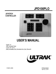
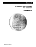
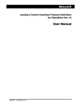
HVBGPIO Version 1.2 User Guide Document 800-02530 – Rev B – 03/10 User Guide Revisions Issue Date Revisions A 03/10 New document B 03/10 Brought into Honeywell template; Updated back cover; minor wording changes 4 HVBGPIO V1.2 User Guide Contents About This Document . . . . . . Overview of Contents. . . . Warranty and Service. . . . Typographical Conventions 1 . . . . . . . . . . . . . . . . . . . . . . . . . . . . . . . . . . . . . . . . . . . . . . . . . . . . . . . . . . . . . . . . . . . . . . . . . . . . . . . . . . . . . . . . . . . . . . . . . . . . . . . . . . . . . . . . . . . . . . . . . . . . . . . . . . . . . . . . . . . . . . . . . . . . . . . . . . . . . . . . . . . . . . . . . . . . . . . . . . . . . . . . . . . . . . . . . . . . . . . . . . . . . . . . . . . . . . . . . . . . . . . . . . . . . . . . . . . . . . . . . . . . . . . . . . . . . . . . . . . . . . . . . . . . . . . . . . . . . . . . . . . . . . . . . . . . . . . . . . . . . . . . . . . . . . . 11 . . . . 11 . . . . 11 . . . . . 12 . . . . . . . . . . . . . . . . . . . . . . . . . . . . . . . . . . . . . . . . . . . . . . . . . . . . . . . . . . . . . . . . . . . . . . . . . . . . . . . . . . . . . . . . . . . . . . . . . . . . . . . . . . . . . . . . . . . . 13 . 14 . 15 . 15 . 16 . . . . . . . . . . . . . . . . . . . . . . . . . . . . . . . . . . . . . . . . . . . . . . . . . . . . . . . . . . . . . . . . . . . . . . . . . . . . . . . . . . . . . . . . . . . . . . . . . . . . . . . . . . . . . . . . . . . . . . . . . . . . . . . . . . . . . . . . . . . . . . . . . . . . . . . . . . . . . . . . . . . . . . . . . . . . . . . . . . . . . . . . . . . . . . . . . . . . . . . . . . . . . . . . . . . . . . . . . . . . . . . . . . . . . . . . . . . . . . . . . . . . . . . . . . . . . . . . . . . . . . . . . . . . . . . . . . . . . 19 . 19 . 21 . 21 . 21 . 21 . 22 . 23 . 24 . 25 . 26 . 27 . . . . . . . . . . . . . . . . . . . . . . . . . . . . . . . . . . . . . . . . . . . . . . . . . . . . . . . . . . . . . . . . . . . . . . . . . . . . . . . . . . . . . . . . . . . . . . . . . . . . . . . . . . . . . . . . . . . . . . . . . . . . . . . . . . . . . . . . . . . . . . . . . . . . . . . . . . . . . . . . . . 29 . 29 . 29 . 29 . 30 . 30 . 30 Relay Outputs . . . . . . . . . . . . . . . . . . . . . . . . . . . . . . . . . . . . . . . . . . . . . 33 Constantly and Pulsed . . . . . . . . . . . . . . . . . . Relay Type Setting . . . . . . . . . . . . . . . . . . . . Setting the Relay Type on the DIP Switch . . . Setting the Relay Type Using the Web Browser 5 . . . . Alarm Inputs . . . . . . . . . . . . . . . . . . . . . . . . . . . . . . . . . . . . . . . . . . . . . . 29 Contact Closure or End-of-Line Resistor Modes. . . . . . CC Mode . . . . . . . . . . . . . . . . . . . . . EOL Mode. . . . . . . . . . . . . . . . . . . . . Sensing . . . . . . . . . . . . . . . . . . . . . . . . . . . Alarm Type Settings . . . . . . . . . . . . . . . . . . . . Setting the Alarm Type on the DIP Switch . . . . Setting the Alarm Type Using the Web Browser . 4 . . . . Web Browser . . . . . . . . . . . . . . . . . . . . . . . . . . . . . . . . . . . . . . . . . . . . . 19 General Operation . . . . . . . . . . . . . . Logging On . . . . . . . . . . . . . Changing the Password . . . . . . Logging Off . . . . . . . . . . . . . Configuration . . . . . . . . . . . . . . . . . Configuring the System. . . . . . . Modifying IP Configuration Settings Setting a User-Defined Protocol . . Importing a Configuration File . . . Exporting a Configuration File . . . Setting the Date and Time Format . Firmware Upgrade . . . . . . . . . . . . . . 3 . . . . Introduction . . . . . . . . . . . . . . . . . . . . . . . . . . . . . . . . . . . . . . . . . . . . . . 13 Overview . . . . . . Layout. . . . . . . . Features . . . . . . LED Indicators . . . DIP Switch Settings. 2 . . . . . . . . . . . . . . . . . . . . . . . . . . . . . . . . . . . . . . . . . . . . . . . . . . . . . . . . . . . . . . . . . . . . . . . . . . . . . . . . . . . . . . . . . . . . . . . . . . . . . 33 . 34 . 34 . 34 UART Ports . . . . . . . . . . . . . . . . . . . . . . . . . . . . . . . . . . . . . . . . . . . . . . 35 Setting the UART Port Mode . . . . . . . . . . . . . . . . . . . . . . . . . . . . . . . . . . . . . . . . 36 Document 800-02530 Rev B 03/10 5 Contents Selecting the UART Stop Bit Length . . . . . . Selecting the UART Data Bit Length . . . . . . Selecting the UART Parity Check Mode . . . . Selecting the UART Baud Rate . . . . . . . . . Selecting the UART Interface Standard . . . . Configuring the UART Settings Using the Web Browser Terminator Resistor. . . . . . . . . . . . . . . . . . . . 6 . . . . . . . . . . . . . . . . . . . . . . . . . . . . . . . . . . . . . . . . . . . . . . . . . . . . . . . . . . . . . . . . . . . . . . . . . . . . . . . . . . . . . . . . . . . . . . . . . . . . . . . . . . . . . . . . . . . . . . . . . . . . . . . . . . . . . . . . . . . . . . . . . . . . . . . . . . . . . . . . . . . . . . . . . 36 . 36 . 37 . 37 . 37 . 38 . 39 Device Control Mode . . . . . . . . . . . . . . . . . . . . . . . . . . . . . . . . . . . . . . . . . 41 Device Control Settings . . . . . . . . . . . . . . . . . . . . . . . . . . . . . . . . . . . . . . . . . . 41 7 PTZ Operation . . . . . . . . . . . . . . . . . . . . . . . . . . . . . . . . . . . . . . . . . . . . . 43 PTZ Protocol Selection . . . . PTZ Aux Function Usage . . . Operation Method . User Define Protocol Format . Appendix A . . . . . . . . . . . . . . . . . . . . . . . . . . . . . . . . . . . . . . . . . . . . . . . . . . . . . . . . . . . . . . . . . . . . . . . . . . . . . . . . . . . . . . . . . . . . . . . . . . . . . . . . . . . . . . . . . . . . . . . . . . . . . . . . . . . . . . . . . . . . . . . . . . . . . . . . . 43 . 44 . 45 . 47 Typical Applications . . . . . . . . . . . . . . . . . . . . . . . . . . . . . . . . . . . 53 VideoBloX System Application . . . . . . . . . . . . . . . . . . . . . . . . . . . . . . . . . . . . . . . 53 MAXPRO-Net Application. . . . . . . . . . . . . . . . . . . . . . . . . . . . . . . . . . . . . . . . . . 54 Appendix B Sample Configuration . . . . . . . . . . . . . . . . . . . . . . . . . . . . . . . . . . 57 System Requirements Connections . . . . . Configuration . . . . . Device Settings . . . . Alarm Configuration . Relay Configuration. . 6 . . . . . . . . . . . . . . . . . . . . . . . . . . . . . . . . . . . . . . . . . . . . . . . . . . . . . . . . . . . . . . . . . . . . . . . . . . . . . . . . . . . . . . . . . . . . . . . . . . . . . . . . . . . . . . . . . . . . . . . . . . . . . . . . . . . . . . . . . . . . . . . . . . . . . . . . . . . . . . . . . . . . . . . . . . . . . . . . . . . . . . . . . . . . . . . . . . . . . . . . . . . . . . . . . . . . . . . . . . . . . . . . . . . . . . . . . . . . . . . . . . . . . . . . . . . . . 57 . 57 . 58 58 . 59 . 60 HVBGPIO V1.2 User Guide Figures Figure 1-1 Front Panel. . . . . . . . . . . . . . . . . . . . . . . . . . . . . . . . . . . . . . . . . . . 14 Figure 1-2 Rear Panel . . . . . . . . . . . . . . . . . . . . . . . . . . . . . . . . . . . . . . . . . . . 14 Figure 1-3 Front Panel Diagnostic LEDs . . . . . . . . . . . . . . . . . . . . . . . . . . . . . . . . . 15 Figure 1-4 DIP Switch Settings on Front Panel . . . . . . . . . . . . . . . . . . . . . . . . . . . . . . 16 Figure 2-1 HVBGPIO User Login . . . . . . . . . . . . . . . . . . . . . . . . . . . . . . . . . . . . . 20 Figure 2-2 Welcome Screen. . . . . . . . . . . . . . . . . . . . . . . . . . . . . . . . . . . . . . . . 20 Figure 2-3 Change Password Window . . . . . . . . . . . . . . . . . . . . . . . . . . . . . . . . . . 21 Figure 2-4 System Configuration Window . . . . . . . . . . . . . . . . . . . . . . . . . . . . . . . . 22 Figure 2-5 IP Configurations Window . . . . . . . . . . . . . . . . . . . . . . . . . . . . . . . . . . . 23 Figure 2-6 User Define Protocol File . . . . . . . . . . . . . . . . . . . . . . . . . . . . . . . . . . . 24 Figure 2-7 Manage Configuration File Window . . . . . . . . . . . . . . . . . . . . . . . . . . . . . . 24 Figure 2-8 Choose File Dialog Box . . . . . . . . . . . . . . . . . . . . . . . . . . . . . . . . . . . . 25 Figure 2-9 Configuration File Successfully Imported . . . . . . . . . . . . . . . . . . . . . . . . . . . 25 Figure 2-10 Configuration File Export . . . . . . . . . . . . . . . . . . . . . . . . . . . . . . . . . . . 26 Figure 2-11 Date Time Format Configurations Window . . . . . . . . . . . . . . . . . . . . . . . . . . 27 Figure 2-12 Software Upgrade Dialog Box . . . . . . . . . . . . . . . . . . . . . . . . . . . . . . . . . 28 Figure 2-13 Software Upgrade Choose File Dialog Box . . . . . . . . . . . . . . . . . . . . . . . . . . 28 Figure 3-1 Alarm Input Connectors . . . . . . . . . . . . . . . . . . . . . . . . . . . . . . . . . . . . 30 Figure 3-2 Alarm Input Type Setting . . . . . . . . . . . . . . . . . . . . . . . . . . . . . . . . . . . 31 Figure 4-1 Relay Output Connectors . . . . . . . . . . . . . . . . . . . . . . . . . . . . . . . . . . . 33 Figure 4-2 Relay Output Type Setting. . . . . . . . . . . . . . . . . . . . . . . . . . . . . . . . . . . 34 Figure 5-1 UART—PTZ Port Connectors . . . . . . . . . . . . . . . . . . . . . . . . . . . . . . . . . 35 Figure 5-2 UART Port Setting Window . . . . . . . . . . . . . . . . . . . . . . . . . . . . . . . . . . 38 Figure 6-1 Device Type Setting (VideoBloX) . . . . . . . . . . . . . . . . . . . . . . . . . . . . . . . 42 Figure A-1 HVBGPIO Typical Application with VideoBloX . . . . . . . . . . . . . . . . . . . . . . . . 53 Figure A-2 HVBGPIO Typical Application with MAXPRO-Net . . . . . . . . . . . . . . . . . . . . . . . 54 Figure A-3 HVBGPIO RJ45 UART Pin-Outs . . . . . . . . . . . . . . . . . . . . . . . . . . . . . . . . 55 Figure B-1 PTZ Settings in NETCFG . . . . . . . . . . . . . . . . . . . . . . . . . . . . . . . . . . . 58 Figure B-2 Device Settings in NETCFG . . . . . . . . . . . . . . . . . . . . . . . . . . . . . . . . . . 59 Figure B-3 Alarm Settings in NETCFG . . . . . . . . . . . . . . . . . . . . . . . . . . . . . . . . . . 60 Figure B-4 Relay Settings in NETCFG. . . . . . . . . . . . . . . . . . . . . . . . . . . . . . . . . . . 61 Document 800-02530 Rev B 03/10 7 Figures 8 HVBGPIO V1.2 User Guide Tables Table 1-1 Front Panel LED Function . . . . . . . . . . . . . . . . . . . . . . . . . . . . . . . . . . . 16 Table 1-2 S1—HVBGPIO Address Setting . . . . . . . . . . . . . . . . . . . . . . . . . . . . . . . . 17 Table 1-3 S2—HBGPIO System Status Parameter Settings . . . . . . . . . . . . . . . . . . . . . . . 17 Table 3-1 Alarm Type Setting . . . . . . . . . . . . . . . . . . . . . . . . . . . . . . . . . . . . . . . 30 Table 4-1 Relay Type Setting . . . . . . . . . . . . . . . . . . . . . . . . . . . . . . . . . . . . . . . 34 Table 5-1 UART Mode Setting. . . . . . . . . . . . . . . . . . . . . . . . . . . . . . . . . . . . . . . 36 Table 5-2 UART Stop Bit Length Setting . . . . . . . . . . . . . . . . . . . . . . . . . . . . . . . . . 36 Table 5-3 UART Data Bit Length Setting . . . . . . . . . . . . . . . . . . . . . . . . . . . . . . . . . 36 Table 5-4 UART Parity Check Setting . . . . . . . . . . . . . . . . . . . . . . . . . . . . . . . . . . . 37 Table 5-5 UART Baud Rate Setting . . . . . . . . . . . . . . . . . . . . . . . . . . . . . . . . . . . . 37 Table 5-6 UART Interface Standard Setting . . . . . . . . . . . . . . . . . . . . . . . . . . . . . . . . 37 Table 5-7 Terminating Resistor Setting . . . . . . . . . . . . . . . . . . . . . . . . . . . . . . . . . . 39 Table 7-1 PTZ Protocol Setting . . . . . . . . . . . . . . . . . . . . . . . . . . . . . . . . . . . . . . 43 Table 7-2 Common Preshot Mapping . . . . . . . . . . . . . . . . . . . . . . . . . . . . . . . . . . . 44 Table 7-3 Pelco D PTZ Preshot Mapping . . . . . . . . . . . . . . . . . . . . . . . . . . . . . . . . . 46 Table 7-4 Diamond PTZ Preshot Mapping . . . . . . . . . . . . . . . . . . . . . . . . . . . . . . . . 46 Table 7-5 VCL PTZ Preshot Mapping . . . . . . . . . . . . . . . . . . . . . . . . . . . . . . . . . . . 46 Table 7-6 IntelliBus PTZ Preshot Mapping . . . . . . . . . . . . . . . . . . . . . . . . . . . . . . . . 47 Table A-1 RJ45 COM1 Pin-Out Definitions . . . . . . . . . . . . . . . . . . . . . . . . . . . . . . . . 54 Document 800-02530 Rev B 03/10 9 Tables 10 HVBGPIO V1.2 User Guide About This Document This document introduces the HVBGPIO, a module that can be mounted in a standard VideoBloX chassis to provide the functions of PTZ control, alarm input, and relay output. Overview of Contents This document contains the following chapters and appendixes: • • • • • • • • • Chapter 1, Introduction, provides an overview of the HVBGPIO and describes the features. It also describes the layout and function of the LEDs and DIP switch settings. Chapter 2, Web Browser, provides procedures for configuring and upgrading the HVBGPIO through a web browser. Chapter 3, Alarm Inputs, describes the two working modes for the 24 alarm inputs and how to configure alarm type settings. Chapter 4, Relay Outputs, covers how to configure the relay outputs. Chapter 5, UART Ports, describes how to configure the UART ports. Chapter 6, Device Control Mode, details how to configure the HVBGPIO to control another device, such as a DVR or multiplexer. Chapter 7, PTZ Operation, covers how to configure the HVBGPIO to control PTZ devices. Appendix A, Typical Applications, describes two typical HVBGPIO applications. Appendix B, Sample Configuration, gives an example of how to operate the HVBGPIO in the VideoBloX system. Warranty and Service Subject to the terms and conditions listed on the Product warranty, during the warranty period Honeywell will repair or replace, at its sole option, free of charge, any defective products returned prepaid. In the event you have a problem with any Honeywell product, please call Customer Service at 1.800.796.CCTV for assistance or to request a Return Merchandise Authorization (RMA) number. Document 800-02530 Rev B 03/10 11 Be sure to have the model number, serial number, and the nature of the problem available for the technical service representative. Prior authorization must be obtained for all returns, exchanges, or credits. Items shipped to Honeywell without a clearly identified Return Merchandise Authorization (RMA) number may be refused. Typographical Conventions This document uses the following typographical conventions: Font What it represents Example Helvetica Keys on the keyboard Press Ctrl+C Lucida Text strings displayed on the screen The message Unauthorized displays. Syntax (object) entered Swiss721 BT Bold Words or characters that you must type. The word “enter” is used if you must type text and then press the Enter or Return key. Italic 12 Enter the password. Menu titles and other items you select Double-click Open from the File menu. Buttons you click to perform actions Click Exit to close the program. Placeholders: words that vary depending on the situation user name Cross-reference to an external source Cross-reference within the document Refer to the VideoBloX User Guide. See Chapter 1, Introduction. 1 Introduction This chapter provides an overview of the HVBGPIO and lists the features. It also shows the front and rear panels and describes the LED indicators and DIP switch settings. Overview The HVBGPIO is a module that can be mounted in a standard VideoBloX chassis, providing the functions of PTZ control, alarm input, and relay output. It can also provide a one-box solution for PTZ control, alarm input, and relay output connectivity. The HVBGPIO has four PTZ ports, four relay outputs, 24 alarm inputs, one serial port, and one Ethernet port. Up to nine protocols can be supported, including Pelco D, Pelco P, Diamond, JVC, and VCL. For extra flexibility, the HVBGPIO also supports a user-defined protocol that allows a user to operate a PTZ device with a protocol that is not one of the product protocols. RS485 can be supported by all four PTZ ports, but RS232 and RS422 is only supported by the PTZ4 port. 24 alarm inputs support two alarm types—Contact Closure (CC) and End of Line (EOL) resistor with two options—Normally Closed (NC) and Normally Open (NO). In EOL mode, a 2.2K Ohm external resistor is required. The COM1 RJ45 port on the rear panel supports both RS232 and RS422. This port is used to receive control commands from MAXPRO-Net. Document 800-02530 Rev B 03/10 13 Introduction Layout The front and rear views are shown below. Figure 1-1 Front Panel LED indicators DIP switch cover plate DIP switches HVB GPIO ETHERNET PWR PTZ1 PTZ2 PTZ3 PTZ4 ALARM RELAY COM1 LNK PTZ1 PTZ2 PTZ3 PTZ4 ALARM RELAY COM1 LNK Remove Cover to Access DIP Switch Settings ACT HVB GPIO ETHERNET PWR Remove Cover to Access DIP Switch Settings S1 ACT Figure 1-2 S2 Rear Panel RELAY 1 A LAR M INPUT ETHERNET COM1 10/100 baseT RJ45 Ethernet LAN COM port port 14 1 2 3 4 5 6 7 8 9 10 11 12 13 14 15 Alarm Input 5.08 mm terminal 16 17 18 19 20 21 22 23 24 RELAY 2 RELAY 3 RELAY 4 NO NC COM NO NO COM NO NC COM NO NC COM Relay Output 5.08 mm terminal PT Z PO R T 1 + 1- 2+ 2- 3+ 3- TX R X 4 + 4 - R X+RX- PTZ ports 5.08 mm terminal HVBGPIO V1.2 User Guide Features The HVBGPIO has the following features: • • • • • • • • • • • • • • 24 alarm inputs, support two kinds of alarm types—CC and EOL resistor—with two options—NC and NO. In EOL mode, a 2.2K Ohm external resistor is required. Four relay outputs, working at up to 1A @ 50V Four Universal Asynchronous Receiver/Transmitter (UART) control ports, supporting up to nine PTZ protocols 10/100 baseT Ethernet LAN connectivity One serial port for communication and control DIP switches for Alarm/Relay/PTZ/COM settings 66.7 MHz processor core Motorola® ColdFire®, 32-bit RISC CPU 16 MB Flash memory for the system firmware uClinux™ embedded operating system Firmware is upgradable using the web browser Non-volatile RAM memory to store downloadable system variables, configuration, and system code extensions Lithium batteries to back up memory Recoverable over current protection Interface protection compliance meets FCC, CE LED Indicators The LEDs on the front panel are used to indicate power, alarm/relay status changes, and communication activities. Figure 1-3 shows the LEDs and Table 1-1 describes their functions. Figure 1-3 Front Panel Diagnostic LEDs HVB GPIO ETHERNET PWR Document 800-02530 Rev B 03/10 PTZ1 PTZ2 PTZ3 PTZ4 ALARM RELAY COM1 LNK ACT 15 Introduction Table 1-1 Front Panel LED Function LED Function PWR Lit when the chassis is powered on. Flickers when the DIP switch status changes. PTZ1 Flickers when valid data passes through the PTZ1 port. PTZ2 Flickers when valid data passes through the PTZ2 port. PTZ3 Flickers when valid data passes through the PTZ3 port. PTZ4 Flickers when valid data passes through the PTZ4 port. ALARM Flickers when status changes on any of the alarm inputs. RELAY Flickers when any of the relays take action. COM1 Flickers when valid data passes through the COM1 port. Ethernet LINK Flickers when data transfer is detected by the Ethernet. Ethernet ACT Flickers when connection is detected by the Ethernet. DIP Switch Settings The HVBGPIO has two DIP switches—S1 and S2—which are used to set up various operational parameters. These switches are accessible by removing the cover plate on the front panel (see Figure 1-1). Figure 1-4 NO NO 16 1 DIP Switch Settings on Front Panel 1 Remove Cover to Access DIP Switch Settings HVBGPIO V1.2 User Guide DIP Switch S1 Use S1 to set the address of the HVBGPIO. Table 1-2 S1—HVBGPIO Address Setting Position Function Description B1-B8 Board Address Valid range is 00000001–11111111(1–255). B1 is the LSB and B8 is the MSB. Note In VideoBloX mode, the valid range for the board address is 1 to 250. The top five addresses are reserved for the alarm concentrator. In MAXPRO-Net mode, the valid range is 1 to 255. DIP Switch S2 Use S2 to set various system parameters for the HVBGPIO. Table 1-3 S2—HBGPIO System Status Parameter Settings Position Function Description B1 Work mode 0 = Slave mode 1 = Master mode B2 IP Address reset 0->1 reset IP Address to the default value B3 COM1 Baud rate setting B4 B3 B4 Baud rate 0 0 9600 1 0 19200 0 1 57600 1 1 115200 B5 COM1 UART mode 0 = RS422 1 = RS232 B6 Configuration mode 0 = DIP Switch setting 1 = Web browser setting B7 Cascade mode 0 = Cascade mode disable 1 = Cascade mode enable. Note This function is reserved. Please set to 0. B8 Document 800-02530 Rev B 03/10 Extended mode 0 = Extended mode disable 1 = Extended mode enable 17 Introduction 18 2 Web Browser This chapter describes how to use the web browser provided to configure and upgrade the HVBGPIO through Ethernet. This method provides more powerful functions than simply configuring the DIP switches as described in Chapter 1. General Operation Logging On To log on to the web browser: 1. In the Internet Explorer (IE) address bar, type in the HVBGPIO URL, then press Enter. The Login window displays (see Figure 2-1). Note The default IP address is 192.168.1.9. You must be running Internet Explorer 6.0.0 or later on your PC. Document 800-02530 Rev B 03/10 19 Web Browser Figure 2-1 2. On the top right corner of the Login window, type in the user name and password, then click Login. The welcome page displays (see Figure 2-2). Note The default user name is Administrator and the default password is 1234, both case sensitive. Figure 2-2 20 HVBGPIO User Login Welcome Window HVBGPIO V1.2 User Guide Changing the Password To change the password: 1. On the top right corner of the Welcome window, click Change Password. The Change Password window displays (see Figure 2-3). Figure 2-3 Change Password Window 2. Type in the current password in the Old Password field. 3. Type in the new password in the New Password field, then retype the new password in the Confirm New Password field. 4. Click Apply to enable the new password. Click Cancel to continue using the old password. Logging Off To exit the system and return to the Login window, click Logout at the top right corner. Document 800-02530 Rev B 03/10 21 Web Browser Configuration Configuring the System To configure various parameters of the HVBGPIO, alarm inputs, and PTZ control: 1. If you have not already done so, log on (see Logging On, page 19). 2. On the CONFIGURATION tab, click System Configurations on the left pane. The System Configurations window displays (see Figure 2-4). Figure 2-4 Note System Configurations Window This page shows the firmware version. If you operate the HVBGPIO in Slave mode, only the version of the board itself displays. In Master mode, you can select other board addresses to get the information of corresponding slave boards, and to configure their settings. 3. Change the values in the fields, as desired. 4. Click Apply to save the changes. Click Default to return the settings to the default values without saving your changes. 22 HVBGPIO V1.2 User Guide Modifying IP Configuration Settings To change the IP configuration settings: 1. On the CONFIGURATION tab, click IP Configurations on the left pane. The IP Configurations window displays (see Figure 2-5). Figure 2-5 2. IP Configurations Window Modify the values of the IP Address, Subnet Mask, and Gateway fields, as desired. Note The default network settings are: IP Address: 192.168.1.9 Subnet Mask: 255.255.255.0 Gateway: 192.168.1.1 3. Click Apply to save the changes. Click Cancel to cancel the current changes. Click Default to return the settings to the default values without saving your changes. Note In the event you have forgotten the IP address, change switch S2.2 from OFF to ON. This resets the IP address to the default value. Setting a User-Defined Protocol If you wish to operate a PTZ device that uses a protocol that is not included, HVBGPIO provides an interface where you can define a protocol file. Follow the specific format provided in Importing a Configuration File, page 24 and Figure 2-6 (they work similarly) to write out the PTZ protocols and upload the files. Then you can select your user-defined protocols in the relevant PTZ fields to operate your PTZ device(s). Document 800-02530 Rev B 03/10 23 Web Browser Each PTZ port should have its own user-defined protocol file. The file used by port 1 will not be used by port 2. If you want this file to be used by both ports, it is recommended that you make two copies of the file and change the port value to 1 or 2, then upload the files. Similarly, if all four ports need the same file, then four separate user-defined protocol files need to be uploaded. Note The Master board can NOT configure the file of Slave boards. Figure 2-6 User Define Protocol File Importing a Configuration File To import a configuration file: 1. On the CONFIGURATION tab, click Config File on the left pane. The Manage Configuration File window opens (see Figure 2-7). Figure 2-7 24 Manage Configuration File Window HVBGPIO V1.2 User Guide 2. Click Browse…. The Choose File dialog opens (see Figure 2-8). 3. Select the configuration file, and then click Open. The address and the name of the file populate. Figure 2-8 4. Click Send to import the configuration file. The message Import Configuration file success indicates the file has been successfully imported. Figure 2-9 Document 800-02530 Rev B 03/10 Choose File Dialog Box Configuration File Successfully Imported 25 Web Browser Exporting a Configuration File To export a configuration file: 1. On the CONFIGURATION tab, in the Export Configuration File area, right-click config.HVBGPIOASCIICONFIG. See Figure 2-8. 2. Select Save target as from the drop-down list. Figure 2-10 Configuration File Export 3. On the Save As dialog, navigate to the desired folder where you wish to save the configuration file. 4. Click Save. The configuration file is exported to your local computer. Setting the Date and Time Format Note This function is only valid for the Master board. To set the date and time format: 1. 26 On the CONFIGURATION tab, click Date Time Format on the left panel. The Date Time Format Configurations window displays (see Figure 2-11). HVBGPIO V1.2 User Guide Figure 2-11 Date Time Format Configurations Window 2. In the Date Time Format drop-down list, select the desired format (for example, DDMMYY). 3. Click Apply to save the changes. Click Default to return the settings to the default values without saving your changes. Firmware Upgrade The HVBGPIO board contains a Flash memory that provides the convenience of upgrading firmware through the Internet. To upgrade the firmware: 1. In the Internet Explorer address bar, type in the HVBGPIO URL, then press Enter. 2. Type in the user name and password, then click Login. 3. Select the UPGRADE tab. The Software Upgrade dialog box appears (see Figure 2-12). Document 800-02530 Rev B 03/10 27 Web Browser Figure 2-12 4. In the Select Folder drop-down list, select one item: Application, FPGA, or KERNEL. Click Browse. A Choose File dialog box prompts you to select the relevant file. 5. Click Open. Figure 2-13 6. Software Upgrade Choose File Dialog Box Click Send to upgrade the file. A success message indicates the firmware has been successfully upgraded. Note 28 Software Upgrade Dialog Box The system reboots automatically after the firmware upgrade has completed. 3 Alarm Inputs This chapter explains the 24 alarm inputs. The alarm inputs can work in either CC or EOL modes. These modes can be configured on DIP switch SW3 or using the web browser. Contact Closure or End-of-Line Resistor Modes HVBGPIO can be set to either open/short circuit sensing or 2.2 kilohm EOL resistor sensing by either DIP switch or through the web browser. CC Mode When configured in CC mode, the HVBGPIO detects contact state changes according to the NO/NC setting (defined in the Alarm Input table in SETMAX or NETCFG). EOL Mode In the EOL mode, setting NC to SETMAX or NETCFG causes an alarm active when the alarm loop becomes either open or shirt circuit (unsealed). Conversely, in the NO mode, the alarm becomes active when the loop is in the sealed position. Sensing Each input can be checked in approximately 1 ms. This means that even with all input circuits enabled, an alarm condition can be recognized in less than 24 ms. There is an alarm de-bounce period of 30 ms, so an alarm input has to stay unchanged for this period Document 800-02530 Rev B 03/10 29 Alarm Inputs before the alarm condition is reported. The LED indicator on the front panel (see Figure 1-1) indicates an alarm state change. The LED indicator shows an alarm state change, regardless of whether the input circuits are enabled or not. Alarm Type Settings Figure 3-1 Alarm Input Connectors A LAR M IN PUT 1 2 3 4 5 6 7 8 9 10 11 12 13 14 15 16 17 18 19 20 21 22 23 24 Setting the Alarm Type on the DIP Switch Alarm type can be set through DIP switches by setting SW2.6 to OFF. Set to OFF Table 3-1 NO NO 1 1 Remove Cover to Access DIP Switch Settings Alarm Type Setting SW3 Description ON OFF 2 CC, EOL of Input 1 to 8 EOL CC 3 CC, EOL of Input 9 to 16 EOL CC 4 CC, EOL of Input 17 to 24 EOL CC Setting the Alarm Type Using the Web Browser To set the alarm type using the web browser: 30 1. After logging on, click the CONFIGURATION tab, then click System Configurations on the left pane. The System Configuration window displays (see Figure 2-4). 2. In the Alarm Input field at the bottom (see Figure 3-2), select EOL or CC from the drop-down lists for each alarm input range (1 to 8, 9 to 16, and 17 to 24). HVBGPIO V1.2 User Guide 3. Click Apply to save the changes. Click Default to return the settings to the default values without saving your changes. Figure 3-2 Document 800-02530 Rev B 03/10 Alarm Input Type Setting 31 Alarm Inputs 32 4 Relay Outputs This chapter covers the four general-purpose relay outputs on the HVBGPIO. Each output circuit provides two kinds of relay contact closures: normally open and normally closed. All output circuits are isolated from each other. The relay contact is completely floating with respect to earth. An output circuit tolerates an applied open-circuit voltage of 50 volts and a closed-circuit loop current not exceeding 1 Amp. As it is a true switch contact, the HVBGPIO is suitable for switching AC supplies. Since all four output circuits are isolated from each other, every polarity and/or reference supply rail can be used by all of the output circuits on the same HVBGPIO. One LED indicator on the front panel (see Figure 1-1) shows all of the output status changes. Figure 4-1 RELAY 1 Relay Output Connectors RELAY 2 RELAY 3 RELAY 4 NO NC COM NO NO COM NO NC COM NO NC COM Constantly and Pulsed You can set the relay outputs to be either energized Constantly or Pulsed. In Pulsed mode, the output energizes momentarily. In Constantly mode, the output does not energize unless it is set to de-energize by the MAXPRO-Net/NETCFG. Document 800-02530 Rev B 03/10 33 Relay Outputs Relay Type Setting Setting the Relay Type on the DIP Switch Relay type can be set on DIP switches by setting S2.6 to OFF. Set to OFF NO NO 1 Table 4-1 Remove Cover to Access DIP Switch Settings 1 Relay Type Setting SW3 Description ON OFF 5 Type of Relay 1 Constantly Pulsed 6 Type of Relay 2 Constantly Pulsed 7 Type of Relay 3 Constantly Pulsed 8 Type of Relay 4 Constantly Pulsed Setting the Relay Type Using the Web Browser To set the relay type using the web browser: 1. After logging on, click the CONFIGURATION tab, then click System Configurations on the left pane. The System Configurations window displays (see Figure 2-4). 2. In the Relay Output field at the bottom (see Figure 4-2), select either Pulsed or Constantly from the drop-down lists for each of the four relays. 3. Click Apply to save the changes. Click Default to return the settings to the default values without saving your changes. Figure 4-2 34 Relay Output Type Setting 5 UART Ports This chapter covers the four UART ports which can send/receive serial command protocols to various protocols compatible with equipment from manufacturers other than Honeywell. For ports 1 to 3, only RS485 is currently implemented. Port 4 can support RS232, RS422, and RS485. Manchester encoding is reserved for SW12, which should be left at the bottom side. HVBGPIO UART ports can be configured to operate in two modes: • • Pan/Tilt/Zoom (PTZ) mode: The PTZ control messages are received on the communications port. Depending on the DIP switch settings, these commands are then translated to serial data packets, which are compatible with other manufacturer’s PTZ telemetry receivers or integrated domes. Device Control mode: Generic device control commands are received and translated into data packets, which are compatible with other manufacturer’s digital video recorders (DVRs), multiplexers, and so on. Figure 5-1 UART—PTZ Port Connectors PT Z PO R T 1+ Document 800-02530 Rev B 03/10 1- 2+ 2- 3+ 3- TX RX 4+ 4- RX+R X- 35 UART Ports Setting the UART Port Mode Table 5-1 lists the HVBGPIO UART mode settings. Table 5-1 UART Mode Setting Position Description ON OFF SW4.2 Port 1 Work Mode Device Control PTZ SW6.2 Port 2 Work Mode Device Control PTZ SW8.2 Port 3 Work Mode Device Control PTZ SW10.2 Port 4 Work Mode Device Control PTZ There is one bit for each port to select the UART setting, including Stop Bit Length, Data Bit Length, Parity Check mode, Baud Rate, and Interface Standard. The detailed settings are listed below. Selecting the UART Stop Bit Length Table 5-2 lists the HVBGPIO UART Stop Bit Length settings. Table 5-2 UART Stop Bit Length Setting Position Description ON OFF SW5.1 Port 1 Stop Bit Length 2 bit 1 bit SW7.1 Port 2 Stop Bit Length 2 bit 1 bit SW9.1 Port 3 Stop Bit Length 2 bit 1 bit SW11.1 Port 4 Stop Bit Length 2 bit 1 bit Selecting the UART Data Bit Length Table 5-3 lists the HVBGPIO UART Data Bit Length settings. Table 5-3 36 UART Data Bit Length Setting Position Description ON OFF SW5.2 Port 1 Data Bit Length 7 bit 8 bit SW7.2 Port 2 Data Bit Length 7 bit 8 bit SW9.2 Port 3 Data Bit Length 7 bit 8 bit SW11.2 Port 4 Data Bit Length 7 bit 8 bit HVBGPIO V1.2 User Guide Selecting the UART Parity Check Mode Table 5-4 lists the HVBGPIO UART Parity Check settings. Table 5-4 Position UART Parity Check Setting None Even Odd B3=0, B4=0 B3=1, B4=0 B3=0, B4=1 Port 1 SW5 Port 2 SW7 Port 3 SW9 Port 4 SW11 Selecting the UART Baud Rate Table 5-5 lists the HVBGPIO UART Baud Rate settings. Table 5-5 Position UART Baud Rate Setting 9600 19200 2400 4800 B5=0, B6=0 B5=1, B6=0 B5=0, B6=1 B5=1, B6=1 Port 1 SW5 Port 2 SW7 Port 3 SW9 Port 4 SW11 Selecting the UART Interface Standard Table 5-6 lists the HVBGPIO UART Interface Standard settings. Table 5-6 Document 800-02530 Rev B 03/10 UART Interface Standard Setting Protocol RS485 RS422 RS232 Port 1 SW5.7=0, SW5.8=0 X X Port 2 SW7.7=0, SW7.8=0 X X Port 3 SW9.7=0, SW9.8=0 X X Port 4 SW11.7=0, SW11.8=0 SW11.7=1, SW11.8=0 SW11.7=1, SW11.8=1 37 UART Ports Configuring the UART Settings Using the Web Browser To change the UART settings using the web browser: 1. After logging on, click the CONFIGURATION tab, then click System Configurations on the left pane. The System Configurations window displays (see Figure 2-4). 2. Select PTZ Control. The PTZ Control window displays (see Figure 5-2). Figure 5-2 3. Modify the parameters according to your requirements. Note 4. UART Port Setting Window For ports 1 to 3, only RS485 is currently implemented. Port 4 can support RS232, RS422, and RS485. Click Apply to save the changes. Click Default to return the settings to the default values without saving your changes. 38 HVBGPIO V1.2 User Guide Terminator Resistor The HVBGPIO provides 120 Ohm terminating resistor selection on the board. Users can simply plug in 120 Ohm jumpers. Table 5-7 Document 800-02530 Rev B 03/10 Terminating Resistor Setting Position Description 120 Ohm NO 120 Ohm P1 For Port 1 RS485 ON OFF P2 For Port 2 RS485 ON OFF P3 For Port 3 RS485 ON OFF P4 For Port 4 RS485/RS422 TxD ON OFF P5 For Port 4 RS422 RxD ON OFF 39 UART Ports 40 6 Device Control Mode This chapter explains Device Control mode. In Device Control mode, generic device control commands are received and translated into data packets compatible with non-Honeywell manufacturers’ DVRs, multiplexers, and so on. Device Control Settings To control your device through the HVBGPIO: 1. From your device CPU, select Device Control mode, Figure 6-1 shows an example of setting HVBGPIO control from a VideoBloX matrix switcher. 2. Set the Device Type according to your CFG / NETCFG PC software. The range of device type is 1 to 32 which responds to setting S5-S4-S3-S2-S1 (SW4, 6, 8, 10) from 00000 to 11111. Example: To set device type 1 in CFG software, change S5-S4-S3-S2-S1 to 00000. In MAXPRONET mode, the usage of device control is straightforward. All the commands received from MAXPRO-Net are passed to all the four output ports. In NETCFG mode, the GPIO card filters out the commands when the device type is different than the device type set on the card. Figure 6-1 shows an example in NETCFG mode. On the HVBGPIO, set port 1 to type 1 and port 2 to type 2. If a type 1 command is received by the GPIO card, the GPIO card transfers the command to port 1; not port 2. Document 800-02530 Rev B 03/10 41 Device Control Mode Figure 6-1 42 Device Type Setting (VideoBloX) 7 PTZ Operation This chapter covers Pan/Tilt/Zoom (PTZ) operation. In PTZ mode, the PTZ control messages are received on the communications port. Depending on the DIP switch settings, these commands are then translated to serial data packets which are compatible with non-Honeywell manufacturer’s PTZ telemetry receivers or integrated domes. Note IntelliBus™ protocol in RS485 mode is not supported by Port 4. JVC protocol is reserved. PTZ Protocol Selection DIP switches S4 to 10 are used to set the protocol for PTZs 1 to 4. Table 7-1 PTZ Protocol Setting PTZ Protocol S4, S6, S8, S10 B8 B7 B6 B5 B4 B3 Pelco D OFF OFF OFF OFF OFF OFF Pelco P OFF OFF OFF OFF OFF ON Diamond OFF OFF OFF OFF ON OFF OFF OFF OFF OFF ON ON OFF OFF OFF ON OFF OFF OFF OFF OFF ON OFF ON AD OFF OFF OFF ON ON OFF IntelliBus™ OFF OFF OFF ON ON ON User-defined OFF OFF ON OFF OFF OFF JVC VCL Panasonic Document 800-02530 Rev B 03/10 S4 for PTZ1 S6 for PTZ2 S8 for PTZ3 S10 for PTZ4 43 PTZ Operation PTZ Aux Function Usage Using the extended Preshot mapping concept, HVBGPIO has the ability to control PTZ devices. Currently we support nine different PTZ protocols. These PTZ protocols have some special functions such as Tour Programming and Menu Call. However, the special functions can vary between different systems and protocols. The extended Preshot mapping concept uses one standard method to map these functions so that it is the same from any system or any protocol. The new method maps Preshot Calls or Sets to call these functions. The Preshot range is from 101 to 198. Table 7-2 shows a brief overview of the Preshot mapping. It defines the united Preshot Call function and Set function. Table 7-2 Common Preshot Mapping Common PTZ Call / Set Function Preshot Mapping 44 No. Call Function Set Function No. Call Function Set Function 101 Menu On Digit or letter input 131 Aux 1 On Aux 1 Off 102 Enter Escape 132 Aux 2 On Aux 2 Off 103 Left Right 133 Aux 3 On Aux 3 Off 104 Down Up 141 Run Learning Tour 1 Program Learning Tour 1 109 Camera Reset Power Reset 142 Run Learning Tour 2 Program Learning Tour 2 110 Error Display On Error Display Off 143 Run Learning Tour 3 Program Learning Tour 3 111 Auto Iris On Auto Iris Off 144 Run Learning Tour 4 Program Learning Tour 4 112 Auto Focus On Auto Focus Off 145 End Learning Tour Function Off 45 113 Digital Zoom On Digital Zoom Off 146 Run Preshot Tour 1 Program Preshot Tour 1 114 BW Mode Color Mode 147 Run Preshot Tour 2 Program Preshot Tour 2 115 Auto BW/Color Function Off 15 148 Run Preshot Tour 3 Program Preshot Tour 3 116 BLC On BLC Off 149 Run Preshot Tour 4 Program Preshot Tour 4 117 Freeze On Freeze Off 150 Function On 50 Program Tour Speed 119 Flashback 180 Flip 151 Function On 51 Program Tour Dwell 120 Store Alarm Pos 1 Recall Alarm Pos 1 152 Function On 52 Program Tour Point 121 Store Alarm Pos 2 Recall Alarm Pos 2 154 Function On 53 Program Autopan Start 122 Sync Early Sync Later 155 Function On 55 Program Autopan End 125 Function On 25 Program Camera Home Pos 161 Clear Privacy Zone Program Privacy Zone 126 Function On 26 Program Camera Home Tour (mimic) 1xx Function On xx Function Off xx 127 Function On 27 Program Camera Home Tour (Preshot) HVBGPIO V1.2 User Guide Operation Method The operation method is as listed below. <MAX system> The user sends a recall Preshot 99 command; then shortly afterwards sends a Recall Preshot XX command which in turn will represent Recall 1XX. The user sends a Recall Preshot 99 command; then shortly afterwards sends a Store Preshot XX command which in turn will represent Store 1XX. When options are selected using a digit or letter, the user sends a Recall Preshot 99; then shortly afterwards sends a Store Preshot 1 and then sends a recall preshot corresponding digit (0–9) or ASCII code (decimal). <VB system> The user sends a Recall Preshot 1XX command which in turn represents Recall 1XX command. The user sends a Store Preshot 1XX commandwhich in turn represents Store 1XX command. The user sends a Store Preshot 101 command; and then shortly afterwards sends a Recall Preshot commandcorresponding digit (0–9) or ASCII code (decimal). Example: To enable MenuOn in a VideoBloX system, simply press these keys on the keyboard: recall-1-0-1-enter. In a MAXPRO-Net system, press recall-9-9-recall-1-enter. To clear the menu in a VideoBloX system, use the ESCAPE command (store 102): press store-1-0-2-enter. In a MAXPRO-Net system, press recall-9-9-store-2-enter. Note In a MAXPRO-Net system, the series of keys should be pressed in sequence fairly quickly. If there is a long delay between keystrokes, the command will be resolved to Recall 99 and Store 1. In some applications, you need to type a digit (0 to 9) or letter. For example, if you should type S to save your setting, you can press Store 101, then Recall 83 (83 is the ASCII code of S). As different PTZs could be implemented by different functions, the following tables list the supported function charts for each supported PTZ protocol. Document 800-02530 Rev B 03/10 45 PTZ Operation Table 7-3 Pelco D PTZ Preshot Mapping Pelco D PTZ Call / Set Function Preshot Mapping No. Call Function Set Function No. Call Function Set Function 109 Camera Reset Power Reset 132 Aux 2 On Aux 2 Off 111 Auto Iris On Auto Iris Off 133 Aux 3 On Aux 3 Off 112 Auto Focus On Auto Focus Off 141 Run Learning Tour 1 Program Learning Tour 1 116 BLC On BLC Off 142 Run Learning Tour 2 Program Learning Tour 2 180 Flip 143 Run Learning Tour 3 Program Learning Tour 3 Aux 1 Off 145 End Learning Tour 119 131 Aux 1 On Table 7-4 Diamond PTZ Preshot Mapping Diamond PTZ Call / Set Function Preshot Mapping No. Call Function Set Function No. Call Function Set Function 101 Menu On Digit or letter input 141 Run Learning Tour 1 Program Learning Tour 1 102 Enter Escape 142 Run Learning Tour 2 Program Learning Tour 2 103 143 Run Learning Tour 3 Program Learning Tour 3 104 146 Run Preshot Tour 1 Program Preshot Tour 1 147 Run Preshot Tour 2 109 Camera reset 116 BLC On BLC Off 148 Run Preshot Tour 3 117 Freeze On Freeze Off 149 Run Preshot Tour 4 119 Flashback Table 7-5 VCL PTZ Preshot Mapping VCL PTZ Call / Set Function Preshot Mapping No. Call Function Set Function No. Call Function Set Function 109 Camera Reset Power Reset 132 Aux 2 On Aux 2 Off 111 Auto Iris On Auto Iris Off 133 Aux 3 On Aux 3 Off 112 Auto Focus On Auto Focus Off 146 Run Preshot Tour 1 113 Digital Zoom On Digital Zoom Off 147 Run Preshot Tour 2 180 Flip 148 Run Preshot Tour 3 119 46 HVBGPIO V1.2 User Guide Table 7-5 VCL PTZ Preshot Mapping VCL PTZ Call / Set Function Preshot Mapping No. Call Function Set Function No. Call Function 122 Sync Early Sync Later 149 Run Preshot Tour 4 Program Camera Home Postion 161 Clear Privacy Zone 125 131 Aux 1 On Set Function Program Privacy Zone Aux 1 Off Table 7-6 IntelliBus PTZ Preshot Mapping IntelliBus PTZ Call / Set Function Preshot Mapping No. Call Func Set Func No. Call Func Set Func 109 Camera Reset Power Reset 141 Run Learning Tour 1 Program Learning Tour 1 111 Auto Iris On Auto Iris Off 142 Run Learning Tour 2 Program Learning Tour 2 112 Auto Focus On Auto Focus Off 143 Run Learning Tour 3 Program Learning Tour 3 113 Digital Zoom On Digital Zoom Off 144 Run Learning Tour 4 Program Learning Tour 4 114 BW Mode Color Mode 145 End Learning Tour 116 BLC On BLC Off 117 Freeze On Freeze Off User-Defined Protocol Format HVBGPIO provides a user-defined protocol format. This allows a user to operate some other third-party protocol PTZs. This section provides an introduction to the user-defined protocol format. = Is an evaluation symbol; the expression or value should follow it in turn. No blank space is allowed between = and the expression/value. <> Is used to mark a system parameter. The parameter must immediately follow the identifier. Both lowercase and capital letters are acceptable. The configuration file should use .udp as the file extension (for example, PelcoD.udp or Diamond.udp). The maximum file size for the configuration file size is 90 kB so be careful not to add too many comments to the file. Document 800-02530 Rev B 03/10 47 PTZ Operation The identifier list is as follows: A. PTZ port setting. This item is required to locate the PTZ port. <Port>=1.2.3.4 Example: If this protocol is desired to be used on PTZ port 3, then write the identifier as <Port>=3 : B. Common command. These items are also required to define the common command format. 1. Move command <MoveRight>,<MoveLeft>,<MoveUp>,<MoveDown> 2. Zoom command <ZoomIn>,<ZoomOut> 3. Focus command <FocusFar>,<FocusNear> 4. Iris command <IrisOpen>,<IrisClose> 5. Preset command <ProgramPreset>,<GotoPreset> 6. Stop command <StopMoveX>,<StopMoveY> <FocusStop>,<ZoomStop>,<IrisStop> Example: If we are coding Move Left command, follow this format: <MoveLeft>=/x00/xII/xSS/x80/x80/xKK : C. 48 Special command. These items are optional to define the special command format. 1. <Init> 2. <SetCamerid> 3. <ProgramPreset100>,<GotoPreset100> to <ProgramPreset198>,<GotoPreset198> HVBGPIO V1.2 User Guide : D. Environmental parameter. These items are also required to define environmental parameters. The default values are: 1. <MinCameraId> 1 2. <MaxCameraId> 255 3. <AllCameraId> 0 4. <MinPreset> 1 5. <MaxPreset> 255 6. <MinLeftSpeed> 1 7. <MaxLeftSpeed> 127 8. <MinRightSpeed> 1 9. <MaxRightSpeed> 127 10. <MinUpSpeed> 1 11. <MaxUpSpeed> 127 12. <MinDownSpeed> 1 13. <MaxDownSpeed> 127 14. <MinZoomInSpeed> 1 15. <MaxZoomInSpeed> 127 16. <MinZoomOutSpeed> 1 17. <MaxZoomOutSpeed> 127 Also you should use some element lists. The list should include some changeable elements as defined below and unchangeable values such as 00 to FF. Each element has a head "\x" (the x should be lowercase). The element should be a hex value. There are five special elements with specific meanings. 1. S The Camera Speed 2. N The Preset Number 3. i The Camera ID 4. K Will be replaced with a calculated checKsum 5. X Will be replaced with a calculated Xor checksum 6. U The AUX function parameter. This parameter can only appear in <ProgramPreset101><ProramPreset119>. It will be replaced with a digit and letter. 7. Y Will be replaced with a calculated checksum (not including the command head) 8. W Will be replaced with a calculated Xor checksum (not including the command head) Document 800-02530 Rev B 03/10 49 PTZ Operation Example: If the camera, speed, and checksum are involved in the command, then write: <MoveLeft>=\x00\xII\xSS\x80\x80\xKK Example of a Typical User-Defined Protocol One entire example is provided for reference. ;======================= Pelco D ;======================= <port>=1 <MinCameraId>=1 <MaxCameraId>=255 <AllCameraId>=255 <MinPreset>=1 <MaxPreset>=255 <MinLeftSpeed>=1 <MaxLeftSpeed>=255 <MinRightSpeed>=1 <MaxRightSpeed>=255 <MinUpSpeed>=1 <MaxUpSpeed>=255 <MinDownSpeed>=1 <MaxDownSpeed>=255 <MinZoomInSpeed>=1 <MaxZoomInSpeed>=255 <MinZoomOutSpeed>=1 <MaxZoomOutSpeed>=255 <MoveLeft>=\xFF\xII\x00\x04\xSS\x00\xYY <MoveRight>=\xFF\xII\x00\x02\xSS\x00\xYY <MoveDown>=\xFF\xII\x00\x10\x00\xSS\xYY <MoveUp>=\xFF\xII\x00\x08\x00\xSS\xYY <ZoomIn>=\xFF\xII\x00\x40\x00\x00\xYY <ZoomOut>=\xFF\xII\x00\x20\x00\x00\xYY <FocusFar>=\xFF\xII\x00\x80\x00\x00\xYY <FocusNear>=\xFF\xII\x01\x00\x00\x00\xYY <IrisOpen>=\xFF\xII\x02\x00\x00\x00\xYY <IrisClose>=\xFF\xII\x04\x00\x00\x00\xYY <ProgramPrest>=\xFF\xII\x00\x03/x00/xNN/xYY <GotoPreset>=\xFF\xII\x00\x07\x00\xNN\xYY <StopMoveX>=\xFF\xII\x00\x00\x00\x00\xYY <StopMoveY>=\xFF\xII\x00\x00\x00\x00\xYY <FocusStop>=\xFF\xII\x00\x00\x00\x00\xYY <ZoomStop>=\xFF\xII\x00\x00\x00\x00\xYY <IrisStop>=\xFF\xII\x00\x00\x00\x00\xYY 50 HVBGPIO V1.2 User Guide <programPreset109>=\xFF\xII\x00\x0F\x00\x00\xYY <gotopreset109>=\xFF\xII\x00\x29\x00\x00\xYY <programPreset111>=\xFF\xII\x00\x2D\x00\x02\xYY <gotopreset111>=\xFF\xII\x00\x2D\x00\x01\xYY <programPreset112>=\xFF\xII\x00\x2B\x00\x02\xYY <gotopreset112>=\xFF\xII\x00\x2Bx00\x01\xYY <programPreset116>=\xFF\xII\x00\x31\x00\x02\xYY <gotopreset116>=\xFF\xII\x00\x31\x00\x01\xYY <programPreset119>=\xFF\xII\x00\x07\x00\x21\xYY <programPreset131>=\xFF\xII\x00\x0B\x00\x01\xYY <gotopreset131>=\xFF\xII\x00\x09\x00\x01\xYY <programPreset132>=\xFF\xII\x00\x0B\x00\x02\xYY <gotopreset132>=\xFF\xII\x00\x09\x00\x02\xYY <programPreset133>=\xFF\xII\x00\x0B\x00\x03\xYY <gotopreset133>=\xFF\xII\x00\x09\x00\x03\xYY <programPreset141>=\xFF\xII\x00\x1F\x00\x01\xYY <gotopreset141>=\xFF\xII\x00\x23\x00\x01\xYY <programPreset142>=\xFF\xII\x00\x1F\x00\x02\xYY <gotopreset142>=\xFF\xII\x00\x23\x00\x02\xYY <programPreset143>=\xFF\xII\x00\x1F\x00\x03\xYY <gotopreset143>=\xFF\xII\x00\x23\x00\x03\xYY <gotopreset145>=\xFF\xII\x00\x21\x00\x00\xYY Document 800-02530 Rev B 03/10 51 PTZ Operation 52 A Typical Applications This appendix provides examples of two typical system applications: when HVBGPIO is used in VideoBloX mode and when it is used with a MAXPRO-Net system. VideoBloX System Application When used in VideoBloX mode, the HVBGPIO should be set to Slave mode. It can receive Bossware protocol from the VideoBloX chassis backplane. One HVBNET16CPU is required as the Master controller. A typical application is shown in Figure A-1. Users can operate a keyboard to control PTZ and DVR devices, and to set alarm sequences to control alarm inputs and relay outputs. Users can also upgrade and configure the VideoBloXx system using the web browser. COM1 COM2 15 14 13 12 11 10 9 8 ALARM INPUT ETHERNET 16 COM1 7 6 RELAY2 RELAY3 5 4 3 2 1 COM3 1 2 3 4 5 6 7 8 9 10 11 12 RELAY1 13 14 15 16 17 18 19 20 21 22 23 24 RELAY4 PTZ PORT NO NCCOMNO NO COM NO NC COMNO NCCOM 1+ 1- 2+ 2- 3+ 3- TX RX 4+ 4- RX+RX- 15 14 13 12 11 10 9 8 7 6 5 4 3 2 1 15 14 13 12 11 10 9 8 7 6 5 4 3 2 1 15 14 13 12 11 10 9 8 7 6 5 4 3 2 1 15 14 13 12 11 10 9 8 7 6 5 4 3 2 1 INPUT 16 PTZ Domes CONTROL 16 ETHERNET HVBGPIO Typical Application with VideoBloX CONTROL Figure A-1 OUTPUT FUSE 20A 16 OUTPUT 16 OUTPUT 16 15 14 13 12 11 10 9 8 7 6 5 4 3 2 1 FUSE PTZ Domes Web Browser DVR Relay Outputs (for example, Sirens) Alarm Sensors Document 800-02530 Rev B 03/10 53 Typical Applications MAXPRO-Net Application The HVBGPIO can also be used with the MAXPRO-Net system. You can either connect the MAXPRO-Net RS232 serial port directly to the HVBGPIO RJ45 serial port, or use an HVB422FT16 extender to extend the serial port to multiple chassis. In this mode, the principal HVBGPIO connected to the MAXPRO-Net should be set to Master mode and other HVBGPIO boards, which get commands from the VideoBloX chassis backplane, should be set to Slave mode. Figure A-2 HVBGPIO Typical Application with MAXPRO-Net MAXPRO-Net / MAX1000 Server H V B 42 2FT 16 8 - 2 0 V AC DC 8 - 30 V D C + 9 10 11 12 13 14 15 1 6 1 2 3 4 5 6 7 8 - Alarm In/Out - GPIO Slave Alarm In/Out - GPIO Master + MATPIT PTZ Ports 1 - 4 E T H E R NE T C O M1 PTZ Ports 1 - 4 Alarm In/Out - GPIO Slave E T H ER N E T C O M1 C O N T RO L C O M1 Video Input Video Input Video Input PTZ Ports 1 - 4 C O N T RO L C O M1 C O N TR O L Alarm In/Out - GPIO Master + MATPIT PTZ Ports 1 - 4 E T H E R NE T E T H ER N E T C O N TR O L T o M a tr ix S la v e C h a n n e l Video Input FU SE 2 0 A F U SE 2 0 A Video Input Video Input Video Input Video Input Video Input Video Input F U SE F U SE The RJ45 COM1 port on the rear panel (p/n 200-0186-E) is defined in Table A-1. Table A-1 54 RJ45 COM1 Pin-Out Definitions Pin Set P1 Jumper for MegaPit Set P1 Jumper for MAX1000 1 RS422 RX[+] RS422 RX[+] 2 RS422 RX[-] RS422 RX[-] 3 NC RS232TX 4 RS232 RX GND 5 GND RS232 RX HVBGPIO V1.2 User Guide Table A-1 RJ45 COM1 Pin-Out Definitions Pin Set P1 Jumper for MegaPit Set P1 Jumper for MAX1000 6 RS232 TX NC 7 RS422 TX[-] / RS485[-] RS422 TX[-] / RS485[-] 8 RS422 TX[+] / RS485[+] RS422 TX[+] / RS485[+] Figure A-3 HVBGPIO RJ45 UART Pin-Outs P1 Jumper for MegaPIT Document 800-02530 Rev B 03/10 P1 Jumper for MAX1000 1 RS422 RX[+] 1 RS422 RX[+] 2 RS422 RX[-] 2 RS422 RX[-] 3 N/C 3 RS232 TX 4 RS232 RX 4 GND 5 GND 5 RS232 TX 6 RS232 TX 7 RS422 TX[-] / RS485[-] 8 RS422 TX[+] / RS485[+] 6 N/C 7 RS422 TX[-] / RS485[-] 8 RS422 TX[+] / RS485[+] 55 Typical Applications 56 B Sample Configuration This appendix provides a sample configuration of how to operate the HVBGPIO in a VideoBloX system. System Requirements For this system, you should have the following requirements: • • • • • • • A PC with HVBNETCFG software installed An HVBNET16CPU connection board An HVBM64 card An HVBGPIO board A PTZ dome A keyboard Appropriate cabling Connections Make the system connections as follows: Document 800-02530 Rev B 03/10 1. Connect the UTP wire from the HVBNET16CPU to the PC. 2. Install the NETCFG software on the PC. 3. Connect the PTZ dome to one of the PTZ ports on the HVBGPIO through RS485. 4. Set the PTZ protocol setting using DIP switch S4 (see PTZ Protocol Selection, page 43). 57 Sample Configuration Configuration In this example, the PTZ dome is connected to UART Port 2 of the HVBGPIO, Address 1 and the PTZ address is 3. The video signal of the PTZ dome is connected to Input 1. Next, configure the corresponding settings in NETCFG: 1. Launch NETCFG. 2. Select the Inputs tab. Figure B-1 PTZ Settings in NETCFG 3. In the Input Number field, select 1. 4. In the Pan / Tilt / Zoom area: a. From the BoardAddr drop-down list, select 1. b. From the Type drop-down list, select PTZ2. c. From the Address field, select 3. Now you can use the keyboard to operate the PTZ. Device Settings To configure device control: 58 1. Launch NETCFG. 2. Select the Devices tab. 3. In the Device Type field, select the device type. HVBGPIO V1.2 User Guide 4. Select the definition files and device addresses appropriate to your installation. Figure B-2 shows typical device settings for a VideoBloX system. Figure B-2 Device Settings in NETCFG Alarm Configuration This section describes how to use alarm sequences where the alarm input (outside) is connected to the alarm input 1 of the HVBGPIO (addressed 1). (The alarm number = alarm input + (HVBGPIO address -1) x 24 = 1). 1. In a practical application, you should select Correct normal status in the Alarm Status, Normal State drop-down list. 2. To enable alarm sequence, select the Enabled checkbox. 3. NETCFG provides two alarm sequences: one for an incoming alarm and one for an outgoing alarm. Document 800-02530 Rev B 03/10 59 Sample Configuration Figure B-3 Alarm Settings in NETCFG Relay Configuration To set relay output 1 on the HVBGPIO board: 1. Select the Sequences tab. 2. Select the OUTPUT command. 3. Parameter 1 of OUTPUT is the HVBGPIO board address. Parameter 2 is the Relay output port Parameter 3 is the state (enabled/disabled) of the relay output. 60 HVBGPIO V1.2 User Guide Figure B-4 Document 800-02530 Rev B 03/10 Relay Settings in NETCFG 61 Sample Configuration 62 Honeywell Security Group (Head Office) 2700 Blankenbaker Pkwy, Suite 150 Louisville, KY 40299, USA www.honeywellvideo.com +1.800.796.2288 Honeywell Security Group Northern Europe Ampèrestraat 41 1446 TR Purmerend, The Netherlands www.honeywell.com/security/nl +31.299.410.200 Honeywell Security Group Europe/South Africa Aston Fields Road, Whitehouse Industrial Estate Runcorn, Cheshire, WA7 3DL, UK www.honeywell.com/security/uk +44.01928.754028 Honeywell Security Group Deutschland Johannes-Mauthe-Straße 14 D-72458 Albstadt, Germany www.honeywell.com/security/de +49.74 31.8 01.0 Honeywell Security Group Caribbean/Latin America 9315 NW 112th Ave. Miami, FL 33178, USA www.honeywellvideo.com +1.305.805.8188 Honeywell Security Group Pacific Level 3, 2 Richardson Place North Ryde, NSW 2113, Australia www.honeywellsecurity.com.au +61.2.9353.7000 Honeywell Security Group Asia 35F Tower A, City Center, 100 Zun Yi Road Shanghai 200051, China www.asia.security.honeywell.com +86 21.5257.4568 Honeywell Security Group Middle East/N. Africa Post Office Box 18530 LOB Building 08, Office 199 Jebel Ali, Dubai, United Arab Emirates www.honeywell.com/security/me +971.04.881.5506 Honeywell Security Group France Immeuble Lavoisier Parc de Haute Technologie 3-7 rue Georges Besse 92160 Antony, France www.honeywell.com/security/fr +33.(0).1.40.96.20.50 Honeywell Security Group Italia SpA Via della Resistenza 53/59 20090 Buccinasco Milan, Italy www.honeywell.com/security/it +39.02.4888.051 Honeywell Security Group España Mijancas 1. 3a planta P.Ind. Las Mercedes 28022 Madrid, Spain www.honeywell.com/security/es +34.902.667.800 www.honeywellvideo.com +1.800.796.CCTV (North America only) [email protected] Document 800-02530 – Rev B – 03/10 © 2010 Honeywell International Inc. All rights reserved. No part of this publication may be reproduced by any means without written permission from Honeywell. The information in this publication is believed to be accurate in all respects. However, Honeywell cannot assume responsibility for any consequences resulting from the use thereof. The information contained herein is subject to change without notice. Revisions or new editions to this publication may be issued to incorporate such changes.