1
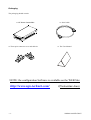
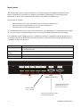
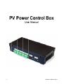
PV Pow P werr Co ontrrol Box Useer Mannual -1- 00MNA0164A ANE-GB 0X X Thank you for choosing a product from our range. The accessories described in this manual are high quality products that have been carefully designed and manufactured to ensure the highest performance. This manual provided detailed instructions on how to use and install the accessory. Please READ THE MANUAL CAREFULLY BEFORE YOU USE THE DEVICE and keep it handy near the device for consultation on how to take full advantage of the features of your new purchase. RPS S.p.A Via Somalia, 20 200032 Cormano (MI) – Italy Tel. +39 02 66327.1 Fax +039 02 66327.231 © No part of this publication may be reproduced without the prior written permission of the manufacturer. The manufacturer reserves the right to make improvements to the equipment described in this manual at any time and without prior notice. -2- 0MNA0164ANE-GB 0X S SA AF FE ET TY Y This part of the manual contains SAFETY instructions that should be followed scrupulously. ¾ The equipment must not be used without a ground connection if it is powered at high voltage. ¾ Ensure that the connectors subjected to high voltages are correctly isolated. ¾ All the models in this range have been built for professional purposes and are therefore not suitable for use in a domestic environment. ¾ The equipment has been designed for use in closed environments. It should not be installed near inflammable liquids, gas or any other toxic substances. ¾ Ensure that water or any other liquid and/or objects do not fall into the equipment. ¾ Do not attempt to repair any failures and/or abnormal operation, but contact the nearest technical support centre. ¾ The equipment must be used only for the purpose for which it was designed. Any other use is considered improper and therefore dangerous. The manufacturer is not liable for any damage caused by improper, incorrect or unreasonable usage of the equipment. -3- 0MNA0164ANE-GB 0X Packaging The packaging should contain: PV Power Control Box Three-pole connector cover and cable tie Serial cable The User Manual NOTE: the configuration Software is available on the WEB Site: http://www.ups-technet.com/ -4- (Photovoltaic Area) 0MNA0164ANE-GB 0X How it works The Photovoltaic Power Control monitors a set of 8 inputs and if a configured condition on the inputs is matched (it is possible to configure a maximum of 24 patterns), it sends appropriate commands to the inverter connected to the Serial 2 port (RS232 or RS485 bus). It is possible to control: - The maximum active power generation (in % of inverter rated power) The reactive power production (in % of inverter rated power) The Power Factor of the generated current. To confirm that all the inverters have received the new set of parameters or commands, it can output on a set of 8 relays a configured single relay or can copy the input pattern on the relais output. It’s compatible with PVSER protocol, so it allows the software compatible with this protocol to act as a bridge towards the RS485 bus where the inverters are connected. In the following table there is a summary of the serial port use. Serial port Serial 1 Serial 2 (RS232 or RS485) Serial 3 UPS Serial RESET Use This serial can be used to update the Photovoltaic Power Control board or for the PVSER protocol where inverters are connected Not used Configuration software serial port. 5V IN1 IN2 GND 5V IN3 IN4 GND 5V IN5 IN6 GND INPUT 1÷ 8 RS232 or RS485 to the inverters 5V IN7 IN8 GND SERIAL 2 5V R/- T/+ GND SERIAL 1 SERIAL 3 UPS SERIAL SERIAL COMMUNICATION PORTS Configuration Serial Port (with the Software PV Power Control Setup) RS232 for monitoring systems and firmware upgrade -5- 0MNA0164ANE-GB 0X Hardwarre configuration: jum mpers RISK OF ELECTRIC C SHOCK. MAK KE SURE TH HAT THE DEVICE D IS SWITCHE ED OFF BEF FORE TOUCHIING THE JU UMPERS. -- PV Power P Contro ol Box -• Remove the cover, by unscrew wing the screews that hoold it in placce, to accesss the jumperss. • Do not switch s on th he device without w the cover, c as soome parts of the circuitt remain pow wered with high h voltage • For safeety, the covver must sccrewed bacck in place using the screws and d washers proovided. In the folloowing figuree we have thhe default jumper settin ngs, positioons highlighhted in red. Hardwarre configuration: DIIP switchees The DIP Sw witch 1 MU UST be set to t on, the otthers to 0. Terminattion resisttance of th he RS‐485 5 bus The devicee is suppliedd with the teermination resistance r already a mouunted inside (Rt=120Ω)). Change the positionn of DIP-sw witch 6 to innsert this ressistance: • • -6- P-switch n° 6 ON → DIP DIP P-switch n° 6 OFF → Rt inserrted Rt not inserted i [DE EFAULT vaalue] 00MNA0164A ANE-GB 0X X Connectors Front view: 230Va L 9Vd N OUT OUT C NC NO C NC NO OUT C NC NO POWER SUPPLY 9Vdc POWER SUPPLY 230Vac OUT OUT C NC NO C NC NO OUT C NC NO OUT OUT C NC NO C NC NO OUTPUT 1÷8 Rear view: RESET 5V IN1 IN2 GND 5V IN3 IN4 GND 5V IN5 IN6 GND INPUT 1÷ 8 5V IN7 IN8 GND SERIAL 2 5V R/- T/+ GND SERIAL 1 SERIAL 3 UPS SERIAL SERIAL COMMUNICATION PORTS STANDARD INPUT CONFIGURATION +5V IN1 IN2 GND OPEN Æ IN1 NOT ACTIVE CLOSED Æ IN1 ACTIVE OPEN Æ IN2 NOT ACTIVE CLOSED Æ IN2 ACTIVE SCHEMATIC DIAGRAM FOR THE INPUT CONNECTION SCHEMATIC DIAGRAM FOR THE OUTPUT -7- 0MNA0164ANE-GB 0X The connectors ALL CONNECTIONS SUBJECTED TO VOLTAGE OF MORE THAN 50V MUST COMPLY WITH SAFETY REGULATIONS 230 Vac Power supply 9 Vdc Power supply PIN # SYMBOL DESCRIPTION PIN # SYMBOL DESCRIPTION 1 L PHASE 1 + + 9 Vdc GROUND 2 - GROUND 2 3 N NEUTRAL OUTPUT 1 - OUTPUT 8 Terminal board NOTE: PIN # SYMBOL DESCRIPTION 1 C COMMON 2 NC NORMALLY CLOSED 3 NO NORMALLY OPEN The “COMMON” contacts of the eight relays are all separate. All the output contacts are at zero potential. -8- 0MNA0164ANE-GB 0X INPUT 1 - INPUT 8 Terminal board STANDARD INPUT CONFIGURATION +5V IN1 IN2 GND PIN SYMBOL # 1 5V 2 IN1 (2) 3 IN2 (3) 4 GND (1) (2) (3) OPEN Æ IN1 NOT ACTIVE CLOSED Æ IN1 ACTIVE DESCRIPTION POWER SUPPLY INPUT 1 INPUT 2 GROUND OPEN Æ IN2 NOT ACTIVE CLOSED Æ IN2 ACTIVE (1) See the “TECHNICAL SPECIFICATIONS” for the maximum loads supported. Depending on the terminal board IN1 (INPUT 1) becomes IN3 (INPUT 3), IN5 (INPUT 5), IN7 (INPUT 7) Depending on the terminal board IN2 (INPUT 2) becomes IN4 (INPUT 4), IN6 (INPUT 6), IN8 (INPUT 8) SERIAL 2 Terminal board SERIAL 1 – SERIAL 3 Connector PIN # SYMBOL 1 5V SIGNAL RS485 RS232 POWER SUPPLY 2 R/- RXTX- 3 T/+ RXTX+ 4 GND PIN # SIGNAL 1 n.c. RXD 2 SERIAL 1 RXD TXD 3 SERIAL 1TXD 4 SERIAL 3 TXD 5 GROUND 6 SERIAL 3 RXD 7 RTS 8 n.c. 9 n.c. GROUND n.c. -9- → not connected 0MNA0164ANE-GB 0X Configuration software In order to configure the Photovoltaic Power Control a configuration software is needed. Download the software from http://www.aros-solar.com To install the software, double-click on PowerControlSetup.exe and follow instructions. The software is installed into C:\Program Files\RPS\PowerControlSetup. Double click on the PowerControlSetup.exe icon. Description The software can configure the Photovoltaic Power Control using a serial connection. Choose the correct serial port, connect the cross serial cable to the “UPS Serial” connector and press the Connect button. The software reads and shows the configuration in a few seconds. - 10 - 0MNA0164ANE-GB 0X The picture shows the “default configuration” and four pattern are configured: Relay 1 closed: no power reduction, no reactive power setting, no power factor setting. Relay 2 closed: active power reduction at 60% , no reactive power setting, no power factor setting. Relay 3 closed: active power reduction at 30% , no reactive power setting, no power factor setting. Relay 4 closed: active power reduction at 0% , no reactive power setting, no power factor setting. With this software is possible: 1. 2. 3. 4. 5. 6. 7. To configure all the parameters needed by Photovoltaic Power Control to operate with at most 16 inverters at the same time To choose any pattern made by 8 inputs and store them on the Photovoltaic Power Control, and configure the appropriate parameters. The pattern “00000000” (all inputs open) is not usable and means inverter default. The maximum number of patterns is 24. To edit any stored input pattern configuration and modify it. To trim the Photovoltaic Power Control parameters To send the modified configuration to the Photovoltaic Power Control To send to the Photovoltaic Power Control a Scan command to automatically report all the connected inverters To restore the parameters to default values, if needed. The main window of the software is divided into sections. The main window sections Input Configuration section This section allows the user to add a specific configuration to the existing list of Active Commands; clicking on a single button on the left side of the section, the user can toggle each button from 0 to 1 and back from 1 to 0. This can be done for each of the 8 buttons (Input1 .. Input8). The chosen pattern can be associated to the P (Active Power), Q (Reactive Power) and COSPHI (Power Factor) parameters. These parameters will be sent to the configured inverters. It’s possible to send also a Power Off or a Power On command. To add the chosen configuration, click on the Add This Configuration button. When the user inputs an invalid configuration an error message informs the user and the configuration is not added. In order to save the added configuration, click on the Save button. Active Commands section The active commands section lists all the valid configurations stored on the Photovoltaic Power Control. Within this section can be set also the number of seconds between commands repetition. Each configured command can be selected. When selected the user can click on the Delete Selected or on the Edit Selected buttons. - 11 - 0MNA0164ANE-GB 0X The first button deletes the selected configuration, while the second one allows the user to review parameters and also to change the input pattern. After the user has done the modifications, the button Save must be clicked to transfer the configuration to the Photovoltaic Power Control. Inverters Configuration section Up to 16 inverters can be added in this section. For each inverter the user can input a serial number (up to 10 chars) and can activate/deactivate the sending of the command. When the Photovoltaic Power Control is connected to the 485 bus, inverters side, clicking on the Scan button activates an automated procedure to acquire the identification number. No inverter are configured Once the procedure ends, the Save button must be clicked to save the configuration on the Photovoltaic Power Control. Five inverter are connected to the PV Power Control Box NOTE: each inverter must have a different IDENT NUMBER (see the inverter manual in order to change this number) Other Parameters section In this section the user can change the following parameters: ¾ ¾ ¾ ¾ ¾ Delay: this time, expressed in seconds, is the time between the acquisition of the input configuration and the effective recognition of the valid input configuration Filter: this time, expressed in seconds, is the time an input configuration must be stable to be acquired. Output Relays for confirm: this is the output relay that will be used in case ALL the inverters have accepted the input configuration Output Relays for denial: this is the output relay that will be used in all other cases. Copy Inputs on Outputs: if the user chooses this option, in case of ALL the inverters have accepted the input configuration, the input configuration itself will be copied on the outputs. In all other cases the output will be NULL. It’s possible also to invert the input logic for each input. - 12 - 0MNA0164ANE-GB 0X Communication Status section In this section the communication status is reported. When the Photovoltaic Power Control is connected, it reports also the firmware release of the equipment. Serial Port section This section allows the user to choose the serial port to use to connect the Photovoltaic Power Control. Board Status section This section is updated in real time while the software is connected. It shows the status of the inputs and of the outputs, the current Photovoltaic Power Control status. Selecting the Log checkbox is possible also to send all to a log file placed in the installation path. Actions section This section contains the following buttons: ¾ ¾ ¾ ¾ ¾ - 13 - Connect: pressing this button the software tries to connect with the Photovoltaic Power Control equipment; when connected it changes to Disconnect. Defaults: pressing this button the software restore to defaults all the parameters. Save: this button sends the current displayed configuration to the Photovoltaic Power Control equipment Scan: this button makes the Photovoltaic Power Control equipment to initiate a scan of the 485 bus to discover automatically the inverters connected. The button changes to Stop. When the scan is complete or interrupted, the found inverters can be saved with the Save button. Quit: exits the application. 0MNA0164ANE-GB 0X Updating the Photovoltaic Power Control firmware To update the firmware of the equipment is necessary: ¾ ¾ ¾ The software to update the firmware, FlashSta.exe The firmware files (ppc.mot and ppc.id) A serial cable, connected between the PC and the PV Power Control Box equipment. The serial cable must be connected on the Serial 1/Serial 3 connector The procedure is as the following: 1. 2. 3. 4. 5. Power the equipment off and shorten pin 1 and 2 of JP13/JP14/JP15 and JP16 Connect the serial cable to the Serial 1/Serial 3 connector and to the PC Power on the equipment. Only the PWR green led should be on Start Flashsta.exe Select the correct serial port and press Ok 6. Into the new window press the Refer… button and browse to the ppc.mot and ppc.id files 7. Select the file Ppc.mot and press Open. - 14 - 0MNA0164ANE-GB 0X 8. Press Ok. A new window appears: 9. Press Erase, confirm and wait until finished . Press Ok once more: 10. Press Program button and confirm the default values, pressing Ok. 11. Presso Ok again - 15 - 0MNA0164ANE-GB 0X 12. The software now is programming the board: 13. Wait until the programming ends: 14. Exit the FlashSta.exe software, remove the jumpers on JP13/JP14/JP15 ad J16, power down the equipment and power it up again or reset. - 16 - 0MNA0164ANE-GB 0X Technical data PV Power Control Box Input voltage 170 - 260 Vac (50 - 60 Hz) OR 9 ± 0.5 Vdc (max. current 600 mA) Operating temperature Storage temperature Relative operating humidity Relative storage humidity Dimensions 0 – 40 °C -5 – 50 °C max.80% max. 90% 265 x 128 x 57 mm (“BOX” version) 1.4 Kg (“BOX” version) Weight 4A @ 250Vac 4A @ 30Vdc Maximum load on each output (OUTPUT 1 - 8) Maximum load per power supply Vdc = 5V 100 mA Vdc = 4.9V @ 20mA Vdc = 4.5V @ 100mA Serial cable specifications (Cross Cable – Female Female) 6 7 8 9 1 2 3 4 5 5 4 3 2 9 8 7 6 1 SERIAL1 - 17 - 0MNA0164ANE-GB 0X Example of schematic diagram connection with Central Inverters at "PV POWER CONTROL BOX" 2 3 6 2 3 PIN 1 2 3 4 5 6 7 8 2 3 2 3 6 JUMPER CONFIGURATION ON THE LAST RS 485 BOARD TERMINATED 2 wires N.C. N.C. N.C. T/+ R/N.C. GND N.C. 2 3 6 2 3 6 6 6 JUMPER CONFIGURATION ON THE RS 485 BOARD NOT TERMINATED JUMPER CONFIGURATION ON THE RS 485 BOARD NOT TERMINATED PV POWER CONTROL BOX 2 3 2 3 6 6 JUMPER CONFIGURATION ON THE RS 485 BOARD NOT TERMINATED PIN 3 2 6 - 18 - 0MNA0164ANE-GB 0X