1
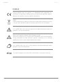
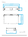
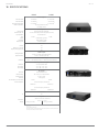
Ver. 1.2
KA24 - KA84
USER GUIDE
English
KA24/KA84
TABLE of CONTENTS
SYMBOLS ................................................................................. 3
1. INTRODUCTION...................................................................... 4
2. KEY features....................................................................... 4
3. APPLICATIONS........................................................................ 4
4. SAFETY information............................................................. 5
5. UNPACKING .......................................................................... 6
6. INCLUDED accessories.......................................................... 6
7. physical.............................................................................. 7
8. INSTALLATION........................................................................ 8
9. ac power............................................................................ 9
10. FRONT PANEL....................................................................... 9
11. BACK PANEL......................................................................... 9
11.1 POWER SUPPLY.................................................................................10
11.2 AUDIO CONNECTIONS.........................................................................10
11.3 REMOTE CONTROL............................................................................. 11
11.4 BRIDGE MODE................................................................................... 13
12. touch screen functions................................................... 14
13. remote control software................................................ 16
14. KA-POT1 ACCESSORY............................................................ 17
14.1 channel levels assignment............................................................. 17
14.2 assembling and wiring................................................................... 18
15. SERVICE ............................................................................ 20
16. Specifications................................................................... 21
2
Ver. 1.2
KA24/KA84
Ver. 1.2
SYMBOLS
K-array declares that this device is in compliance with applicable CE
standards and regulations. Before putting the device into operation, please
observe the respective country-specific regulations!
WEEE
Please dispose of this product at the end of its operational lifetime by bringing
it to your local collection point or recycling center for such equipment.
This symbol alerts the user to the presence of recommendations about the
product’s use and maintenance.
Warning! Dangerous voltages: RISK of electric shock.
Terminals marked with this symbol are HAZARDOUS LIVE and the external
wiring connected to these terminals requires installation by a qualified
professional or the use of ready-made leads or cords.
This symbol alerts the user to the presence of recommendations about
product’s use and maintenance.
This device complies with Restriction of Hazardous Substances Directive.
3
KA24/KA84
Ver. 1.2
1. INTRODUCTION
The K-array KA line of power amplifiers are comprised of KA24 and KA84. The KA24 has 4 channels
per 500W on 4Ω and the KA84 has 4 channels per 2000W on 4Ω. Each model has 4 fully independent
and configurable channels. The integrated DSP offers EQ, Matrix, Levels, Delays and Limiter functions
on every channel, to avoid the need of external additional processors. The front panel has an
easy-to-use touchscreen that gives access to all the basic functions for quick setup and corrections.
The KA24 and KA84 can be used as a mixer for fixed installations thanks to the microphone and
Phantom power options available on every analog IN. 2 GPIO ports give easy external analog controls
using K-array accessories.
An on-board K-array speaker preset library gives an optimal and easy configuration for endless
combinations. All DSP functions are remote controlled via the K-framework software over RS485 (3-pin
XLR) or integrated USB connector.
Both amplifiers are built into a 2U light weight aluminium chassis and come with a kit of removable
rack adapters and four rubber pads for flat surfaces.
KA amplifiers feature optical limiters, and protection against over heating, over current and short
circuits.
All KA components are designed by the K-array R&D department and custom made under the K-array
quality control system.
2. KEY features
3. APPLICATIONS
• 2000 W or 8000 W in just 2 rack units
• 4 analog IN and 2 AES-EBU IN to 4 fully
configurable OUT
• 2 GPIO for external analog controls
• Mix sensitivity and phantom power is available in all 4 analogue inputs.
• Integrated DSP with processing, matrix and
delays
• On-board touch screen for easy access functions
• K-array loudspeakers presets already on-board
• RS485 and USB connectivity for remote control
•
•
•
•
•
4
Theatrical sound reinforcement
Concert halls, clubs, house of worship
Exhibit audio for museum displays
Cinema and installed AV systems
Touring PA and Monitoring
KA24/KA84
Ver. 1.2
4. SAFETY information
Read these instructions - Keep these instructions - Heed all warnings
Warning. Failure to follow these safety instructions could result in fire,
shock or other injury or damage to the device or other property.
This symbol alerts the user to the presence of
recommendations about the product’s use and
maintenance.
The lighting flash with arrowhead symbol within
an equilateral triangle is intended to alert the
user to the presence of uninsulated, dangerous
voltage within the product enclosure that may
be of magnitude to constitute a risk of electrical
shock.
IMPORTANT SAFETY INSTRUCTIONS
• Read these instructions.
• Keep this instructions.
• Heed all warnings.
• Follow all instructions.
• Do not use this apparatus near water.
• Clean only with dry cloth.
• Do not block any ventilation openings. Install in accordance with the manufacturer’s instructions.
• Do not install near any heat sources such as radiators, heat registers, stoves, or other apparatus
(including amplifiers) that produce heat.
• Do not defeat the safety purpose of the polarized or grounding-type plug. A polarized plug has two
blades with one wider than the other. A grounding type plug has two blades and a third grounding prong.
The wide blade or the third prong are provided for your safety. If the provided plug does not fit into your
outlet, consult an electrician for replacement of the obsolete outlet.
• Protect the power cord from being walked on or pinched particularly at plugs, convenience receptacles,
and the point where they exit from the apparatus.
• Only use attachments/accessories specified by the manufacturer.
• Use only with the cart, stand, tripod, bracket, or table specified by the manufacturer, or sold with the
apparatus.
• When a cart is used, use caution when moving the cart/apparatus combination to avoid
injury from tip-over.
• Unplug this apparatus during lightning storms or when unused for long periods of time.
• Refer all servicing to qualified service personnel. Servicing is required when the apparatus has been
damaged in any way, such as power-supply cord or plug is damaged, liquid has been spilled or objects
have fallen into the apparatus, the apparatus has been exposed to rain or moisture, does not operate
normally, or has been dropped.
5
KA24/KA84
Ver. 1.2
WARNING
• S
ince the device is a CLASS I apparatus, it must be only connected to an AC three-wire grounding outlet.
If your outlet isn’t grounded, contact a licensed electrician to replace it with a property grounded
outlet.
• To reduce the risk of electric shock, disconnect the amplifier from the AC mains before installing audio
cable. Reconnect the power cord only after making all signal connections. Do not use the product if
the power cord is broken or frayed. Protect the power cord from being walked upon or pinched.
• To completely disconnect this apparatus from the ac mains, disconnect the power supply cord plug
from the ac mains connector.
• Voltage requirement. Make sure that the supplied voltage stays within the specified range. Verify that
your mains connection satisfies the power ratings of the device.
• Only connect the power supply to an appropriate power outlet.
• Do not install the amplifier in wet or humid locations without using weather protection.
• TO REDUCE THE RISK OF FIRE OR ELECTRIC SHOCK, do not expose this apparatus to rain or moisture
and objects filled with liquids, such as vases, should not be placed on this apparatus.
• The main plug of the power supply cord shall remain readily accessible.
CAUTION
• C
hoking Hazards. This device contains small parts, which may present a choking hazard to small
children. Keep the device and its accessories away from small children.
• Temperature. Operate the device in a place where the temperature is between -20°C and 35°C (-4°F
to 95° F). Avoid dramatic changes in temperature or humidity when using it, as condensation may
form on or within the device.
• Do not make repairs yourself. Caution, risk of electric shock. Do not open the device, it contains
potentially hazardous voltage. Never attempt to disassemble, repair or modify the system yourself.
Disassembling the unit may cause damage that is not covered under the warranty. The device contains
no user-serviceable parts. Repairs should only be performed by factory trained service personnel. Do
not plug the power cord in if you suspect that your device needs service or repair.
5. UNPACKING
6. INCLUDED accessories
Each K-array amplifier is built to the highest
standard and thoroughly inspected before leaving
the factory. Upon arrival, carefully inspect the
shipping carton, then examine and test your new
amplifier. If you find any damage, immediately
notify the shipping company. Only the consignee
may institute a claim procedure regarding the
system’s electronic equipment.
•
•
•
•
6
Power cable 3 m
USB cable 1.8 m
Rubber pads for flat surfaces installation
Rack brackets
KA24/KA84
Ver. 1.2
7. physical
480 mm (18.9")
304.8 mm (12.0")
7
304.8 mm (12.0")
294.8mm (11.6")
94.9 mm (3.7")
430 mm (16.9")
Weight
KA24: 5.5 Kg (12.12 lb)
KA84: 6.1 Kg (13.45 lb)
KA24/KA84
Ver. 1.2
8. INSTALLATION
KA24 and KA84 are two rack units high (2U) and can be mounted in an EIA-standard 19’’ rack using
two rack adapters (included). In case of istallation on a flat surface, use the four rubber pads included.
To maintain a low and even operating temperature, the amplifier contains two fans on the right side.
The figure below shows the air flow:
WARNING
For effective cooling, do not obstruct the ventilation openings.
8
KA24/KA84
Ver. 1.2
9. ac power
KA24 and KA84 operate safely and without audio discontinuity if the AC voltage stays within an operating
range of 90 V to 264 V (nominal range: 100-240 V) at 50-60 Hz. Please verify that your AC main
connections are capable of satisfying the power rating for the device.
CAUTION. Do not connect the system to AC power mains exceeding 265 V. Doing
so will cause significant damage to the device and create serious risk for users!
10. FRONT PANEL
1
2
1. TOUCH SCREEN Control panel. Provides access to the main functions of the DSP on board (see Section 12)
2. POWER SWITCH. Turns the amplifier on and off.
11. BACK PANEL
13
3
24
20
14 12
9
8
11
10
7
6
22
16
15
23
CH 5 - 6
16
5
4
27
9
26
25
21
18 17
19
28
KA24/KA84
Ver. 1.2
11.1 POWER SUPPLY
3
4
5
CH 5 - 6
3. AC INPUT. PowerCon for AC power.
4. AC LINK. PowerCon ouput for feeding AC mains
power to additional K-array components with a
powercon AC input socket.
5. POWER ON LED. Indicates the amplifier is ON.
11.2 AUDIO CONNECTIONS
6. CH 1 MIC/LINE INPUT. XLR analog input, with
selectable sensitivity for Mic (-30 dBu) or Line (+4 dBu).
CH 5 - 6
7. CH 2 MIC/LINE INPUT. XLR analog input, with
selectable sensitivity for Mic (-30 dBu) or Line (+4 dBu).
8. CH 3 MIC/LINE INPUT. XLR analog input, with
selectable sensitivity for Mic (-30 dBu) or Line (+4 dBu).
9. CH 4 MIC/LINE INPUT. XLR analog input, with
selectable sensitivity for Mic (-30 dBu) or Line (+4 dBu).
21
19 18
17
10. CH 1 MIC/LINE SWITCH. Selects CH 1 input
sensitivity for Mic (pressed) or Line (depressed) level.
11. CH 2 MIC/LINE SWITCH. Selects CH 2 input sensitivity for Mic (pressed) or Line (depressed) level.
12. CH 3 MIC/LINE SWITCH. Selects CH 3 input sensitivity for Mic (pressed) or Line (depressed) level.
13. CH 4 MIC/LINE SWITCH. Selects CH 4 input sensitivity for Mic (pressed) or Line (depressed) level.
14. PHANTOM POWER SWITCH. Turns phantom power (48 V) on (pressed) / off (depressed) on CH 1,
CH 2, CH 3, CH 4 inputs (only for channels with MIC/LINE SWITCH pressed).
15. CH 1 PARALLEL OUT. XLR parallel output, providing a direct signal from the CH 1 Input. This output
cannot be processed or controlled via the K-Framework software.
16. CH 2 PARALLEL OUT. XLR parallel output, providing a direct signal from the CH 2 Input. This output
cannot be processed or controlled via the K-Framework software.
17. CH 3 PARALLEL OUT. XLR parallel output, providing a direct signal from the CH 3 Input. This output
cannot be processed or controlled via the K-Framework software.
18. CH 4 PARALLEL OUT OR DSP OUT. This XLR connector provides a direct signal from the CH 4 Input
when the switch 19 is depressed. In that case, this output cannot be processed or controlled via the
K-Framework software. Otherwise, when the switch 19 is pressed, this XLR acts as an auxiliary XLR
balanced output, controlled via the K-Framework software. Users can select the signal routed to this
output.
10
KA24/KA84
Ver. 1.2
19. CH 4 LINK OUT/DSP OUT SWITCH. Press the switch to use output 18 as an auxiliary XLR balanced output
controlled via the K-Framework software.
20. CH 5/6 AES/EBU INPUT. XLR input connector for two-channel AES/EBU digital audio, accepting sample
rates from 32 kHz – 96 kHz.
21. CH 5/6 AES/EBU OUTPUT. XLR output, providing two-channel digital audio from ch 5/6 AES/EBU input,
at a sample rate of 48 kHz.
22. POWER OUT A. Speakon output to drive passive speakers. 1+/1- provides OUT A1, 2+/2- provides OUT
A2.
23. POWER OUT B. Speakon output to power passive speakers. 1+/1- provides OUT B1, 2+/2- provides OUT B2.
SPEAKON OUT A
SPEAKON OUT B
2+
2+
1-
2-
1-
2-
1+
1+
Speakon wiring diagram
11.3 REMOTE CONTROL
24. REMOTE RS485 LINK INPUT. XLR input for
24
connecting the amplifier from another RS485
CH 5 - 6
device in a K-Framework network. RS485 Link
Input can also be used to connect a computer
running the K-Framework software (requires
K-USB USB-to-RS485 adapter).
25. REMOTE RS485 LINK OUTPUT. XLR output
for connecting additional RS485 devices in a
K-Framework network.
26. REMOTE USB Input. Connects a computer running the K-Framework software, for remote control of
the amplifier. Users can manage an entire network of RS485 devices with one PC connected via USB.
27. EXTENSION CONNECTOR. Multi-pin connector for various K-array extension modules, for wireless control and audio transmission, memory extension, digital signal encoding and audio reproduction.
28. K A-POT1 CONNECTOR. These two analog GPIO ports allow the user to control same amplifier’s
parameters using the K-POT1 accessory. See Section 14 for further information about these feature.
11
KA24/KA84
Ver. 1.2
USB connection from a PC
CH 5 - 6
RS485 XLR LINK
CH 5 - 6
RS485 XLR LINK
CH 5 - 6
Next device in the K-framework network
RS485 network
12
KA24/KA84
Ver. 1.2
11.4 BRIDGE MODE
The bridge configuration is optional for end users who want to drive third party loudspeakers using
K-array amplifiers. K-array speakers ARE NOT designed to use the bridge configuration if not specified
on the official user’s manual.
The extra power that the bridge configuration can deliver can damage K-array speakers if not used under
K-array specifications.
To use the bridge configuration, follow the instruction below:
1. In the Output Configuration Page (on the touch screen or via the K-framework software) select the
same preset on both channels (A1 and A2 or B1 and B2).
2. In the Matrix Page, send the same signal to both outputs.
3. O
n the KA24 take the signal from 2+ (positive) 1- (negative). On the KA84 take the signal from 1+
(positive) 2- (negative).
2+
2+
1-
21+
1+
KA84
KA24
- +
13
1-
2-
- +
Bridge mode will provide
KA24: 2 x 1000 W @ 8 Ω
KA84: 2 x 4000 W @ 8 Ω
KA24/KA84
Ver. 1.2
12. touch screen functions
The main functions of the onboard DSP can be managed with the integrated touch screen. Functions are
grouped into six pages, shown as icons on the Home page.
HOME PAGE
To reach the Home page from any other page,
touch the Home button.
LEVELS
The Levels page allows users to independently manage
the amplitude of all the four input channels and all the
four output channels.
Click the arrow button on the top right corner to switch
between Input levels page and Output levels page.
MATRIX
The Matrix page allow users to manage the routing of the
four input channels to the four output channels.
14
KA24/KA84
Ver. 1.2
DELAY
The Delay page allows users to independently set the
delays for the four output channels (up to 3.5 mt) and for
Channel 3 and Channel 4 input channels (up to 114 mt).
Pressing on a delay value, users can set the delay in ms
or in mt. Press the OK button to return to the Delay page.
CONFIGURATION
Before connecting the speakers to the amplifier, follow
the instructions below.
Warning. Failure to follow these instructions
could result in serious damage to the
speakers connected to the amplifier!
Go to the Configuration page and press the SETUP
button. Insert the model and the number of speakers
connected to Output A1. Press the arrow button on the
top right corner.
Insert the model and the number of speakers you want
to match to the previous ones. For example, if you
have two KP102 mid-high arrays connected to the A1
output and a KMT21P sub connected to another output
(or to another amplifier) select KMT21P to the A1 Out
Match page and the DSP will compute automatically the
crossover setting to obtain a perfect match between the
speakers. Press the arrow button on the top right corner.
Repeat step 2 and 3 for all other outputs. At the and
you will return to the main Configuration page. Press
APPLY to load all settings. The DSP will automatically
adjust the parameters on each output channel to match
the requirement for the speakers connected.
Warning. If you are using speakers with selectable impedance, pay
attention to set the value indicated in the Configuration page!
15
KA24/KA84
Ver. 1.2
PRESET
The Preset page allows users to load presets stored
on-board.
INFO
The Info page contains information about the
current software and firmware, and the Board ID
of the amplifier. When connecting the amplifier in
a K-framework network, please make sure that all
devices in the network have different ID numbers.
13. remote control software
All amplifier functions, including signal routing, output configuration, channel equalization and delay can
be controlled via K-Framework software.
To download your free K-Framework software and K-Framework User Guide, please navigate to the
K-array website http://www.k-array.com/software_download
16
KA24/KA84
Ver. 1.2
14. KA-POT1 ACCESSORY
KA-POT1 allows users to control input channels and output channels levels with a potentiometer installed
in a standard box for switches. It is possible to connect up to two independent KA-POT1 to each amplifier
in order to control two independent levels.
14.1 channel levels assignment
To assign each KA-POT1 an amplifier parameter, connect a computer running the K-framemork software
and follow the instruction you find in the K-framework manual. As shown in the window below, users can
assign each KA-POT1 one or more channel levels. In the example below, the first KA-POT1 controls all
input channel volumes and the second controls all output channel volumes.
17
KA24/KA84
Ver. 1.2
14.2 assembling and wiring
The KA-POT1 pack is composed of:
PCB with potentiometer
2 x screws M3X6
2 x 4-pin connector plugs
Ø4
Ø7
Ø4
Drilling jig
KA-POT1 UNPACKING
Position the drilling jig on an appropriate box and make the three holes. Install your cap in a box for
switches and insert the PCB with the potentiometer coming out from the center hole. Secure with the
two included screws. Cover the potentiometer with the gray knob.
18
KA24/KA84
Ver. 1.2
Follow the wiring scheme below to connect the 4-pin connector plugs. Follow the scheme on the top if
you own only one KA-POT1 and the one on the bottom if you own two KA-POT1. Then insert one plug
in the PCB and the other into the GPIO port on the amplifier.
KA-POT1 WIRING
19
KA24/KA84
Ver. 1.2
15. SERVICE
To obtain service:
1) Contact the official K-array distributor in your country. Your local distributor will direct you to the
appropriate service center.
2) If you are calling for service, please have the serial number(s) of the unit(s) available for reference. Ask
for Customer Service, and be prepared to describe the problem clearly and completely.
3) If the problem cannot be resolved over the phone, you may be required to send the unit in for service.
In this instance, you will be provided with an RA (Return Authorization) number which should be
included on all shipping documents and correspondence regarding the repair. Shipping charges are the
responsibility of the purchaser.
Any attempt to modify or replace components of the device will invalidate your warranty. Service must
be performed by an authorized K-array service center.
Cleaning:
Use only a soft, dry cloth to clean the housing. Do not use any solvents, chemicals, or
cleaning solutions containing alcohol, ammonia, or abrasives. Do not use any sprays near
the product or allow liquids to spill into any openings.
20
KA24/KA84
Ver. 1.2
16. Specifications
KA24
KA84
Power Output
Max Power @ 4Ω
4 x 600 W
Max Power @ 8Ω
4 x 300 W(1)
4 x 1000 W(1)
2 x 1200 W(1)
2 x 4000 W(1)
Max Power bridged @ 8Ω
4 x 2000 W(1)
(1)
4 Ω (single channel mode)
8 Ω (bridge mode)
Minimum impedance
Audio specs
50V/μS (input filter bypassed)
Slew rate 8 Ω
Distortion (THD + N)
< 0.09% 1W to full power @ 4Ω (typically <0.05%)
10 kΩ balanced
Input impedance
26 dB
Gain
32 dB
Unbalanced to ground
Output
20Hz 20KHz (+-1dB)
Bandwidth
> 10000 @ 100Hz
Damping factor
Protection
Thermal
Yes
Short circuit / over-load
Yes
Clip limit, Analog signal limit
Yes
Audio Input
Analog Connectors
4 male + 4 female 3-pin balanced XLR
Digital Connectors
1 male + 1 female 3-pin XLR
Remote control Input
Connectors
1 male + 1 female XLR parallel / 1 USB B Jack serial converter
Audio powered Output
2 x 4-pin Speakon NL4
Connectors
NL4 1 wiring
1+1- = A1 | 2+2- = A2
NL4 2 wiring
1+1- = B1 | 2+2- = B2
AC power
2 x PowerCon IN/OUT
Connector
Nominal voltage
100 - 240 V, 50 - 60Hz with PFC
Operating Range
AC 90V - 264V
>79%(typical)
Efficiency
220 W
1/8 rated power (pink noise)@ 8Ω
600 W
1/8 of max output power @ 4Ω
Thermal dissipation
180 BTU/h
621 BTU/h
1/4 of max output power @ 4Ω
396 BTU/h
1154 BTU/h
Certification
20
IP
Physical
426 mm x 304 mm x 88.2 mm
(19.1“ x 12” x 3.5 “)
Dimensions
Weight
5.5 Kg (12.12 lb)
6.1 Kg (13.45 lb)
Notes for data
1. EIAJ Test Standard, 1KHz, 1%THD
New materials and design are introduced into existing products without previous notice. Present systems may differ
in some respects from those presented in this catalogue.
21
KA24/KA84
Ver. 1.2
The contents of this manual are furnished for informational purposes only. K-array s.u.r.l. assumes no responsibility for any errors or inaccuracies that may appear
in this manual. K-array s.u.r.l. reserves the right to make modifications without prior notice.
22