1
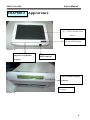
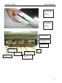
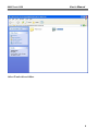
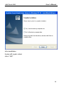
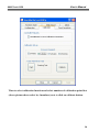
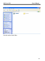
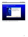
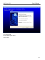
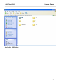
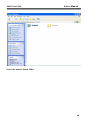
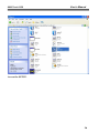
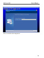
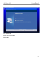
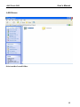
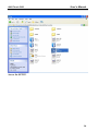
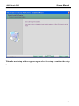
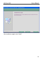
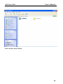
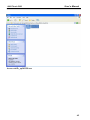
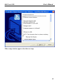
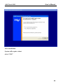
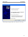
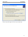
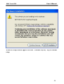
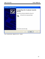
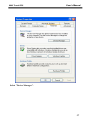
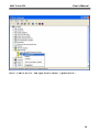
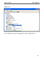
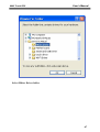
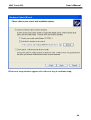
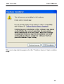
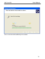
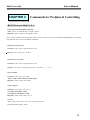
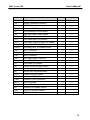
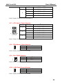
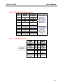
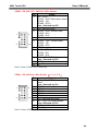
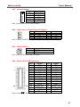
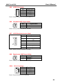
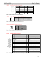
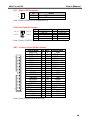
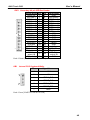
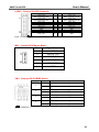
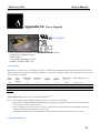
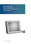
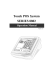
11/06/2007 JARLTECH ISO 9001 Certified Lead with technology Win customers with service Touch POS System SERIES 8802 OPERATION MANUAL 8802 Touch POS User’s Manual Table of Contents: Chapter 1 Specification introduction ........................................................................................... 3 Chapter 2 Appearance ......................................................................................................................... 4 Chapter 3 Installation .......................................................................................................................... 7 Chapter 4 Commands for Peripheral Controlling ................................................................. 72 Chapter 5 Hardware Configuration ............................................................................................. 75 Chapter 6 Hardware Specification ................................................................................................. 93 Appendix – Power supply .................................................................................................................... 95 2 User’s Manual 8802 Touch POS CHAPTER 1 Specification Introduction Preview Jarltech is defining the New Age of POS with its integrated TouchPOS. The 8802 is designed on NB base with Intel Celeron M processor 1.5 GHz, One slot of DDR DIMM memory max up to 1GB; 12.1” TFTLCD with resistive touch screen; built-in VGA, LAN chip, Internal IDE Hard disk (20GB or above); includes Magnetic card reader and 20X2 customer VFD display, XGA 1024 x 768 Resolution, wireless 802.11 b/g. Thus designation helps user easy and comfortable to handling. Its multi-functional capability makes it suitable for software developments under Windows XP, XP Embedded, XP professional for Embedded, WIN 2000 professional Embedded, WIN NT 4.0, Linux, Redhat 7.2, WIN98, ME. The brand new Touch POS 8802 has been designed with all advantages from JARLTECH POS series, but less cost to customer with its interactive transaction, RFID and smart card reader design provides multiple clerk access and customer database management, suitable and superior for super-market; hotel; convenience store; restaurants and any organization or store that needs point of service. Following description helps user understand what integrated part in 8802 TouchPOS. 3 User’s Manual 8802 Touch POS CHAPTER 2 Appearance 12.1” TFT-LCD with Touch Screen System LED indicator (Figure 1-1) Magnetic Strip Reader RFID (Option) (Option) 20X2 Customer Display (Option) I/O ports (Figure 1-2) 4 User’s Manual 8802 Touch POS Extend USB (Option) Extend IDE (Option) Cash draw port Printer port AC power COM1 COM2 VGA port PS2/KB port Fan AUDIO IN / OUT USB port 5 8802 Touch POS LCD Back light adjustment button User’s Manual AC power switch COM1/COM2: Standard DB9 PIN Serial port Mouse: PS2 mouse socket K/B: PS2 Keyboard socket USB: USB port X 2 VGA: 15 Pins VGA Connector LAN: Ethernet connector Multi-Media: Line Out / MIC / Line-In CD1/CD2: Cash Draw 1(beside SW) and Cash Draw 2 SW: Switch button – SW1 SW2; ↓ = ON, ↑= OFF (Default SW1=OFF , SW2=OFF) Power: Connect to ATX power supply 6 User’s Manual 8802 Touch POS CHAPTER 3 Driver Installation Touch Drivers Insert CD Rom and select driver & manual folder. 7 8802 Touch POS User’s Manual Select Touch driver folder. 8 8802 Touch POS User’s Manual Access setup of 519d2166xp2k.exe 9 8802 Touch POS User’s Manual Skip out the previous setup screen and select next step. 10 8802 Touch POS User’s Manual After installation System will require reboot select “YES” 11 8802 Touch POS User’s Manual When first time complete Touch installation, require processing the cursor accuracy calibration, Search for the Touchset utility shortcut on the desktop and select Touchset utility to set up. 12 8802 Touch POS User’s Manual When configuration window appear, select the language which you desire (As above selected picture explanation) 13 8802 Touch POS User’s Manual Than to select calibration function and select numbers of calibration point first (above picture shows select by 4 numbers) next to click on calibrate button. 14 8802 Touch POS User’s Manual The screen will shows as above picture, use the Touch pen to point on dot to align the cursor, if the actual alignment has too much difference than the system will skip back to previous screen and require calibration once again. 15 8802 Touch POS User’s Manual The numbers of the calibration point shows on the screen will depend on the number you have set previously, after complete system will skip back to desktop (if the cursor still not accurate please repeat the calibration again). 16 8802 Touch POS User’s Manual IDE Drivers Insert CD Rom and select driver & manual file folder. 17 8802 Touch POS User’s Manual Select the mother board folder. 18 8802 Touch POS User’s Manual And select IDE folder. 19 8802 Touch POS User’s Manual Access the infinst_autol.exe 20 8802 Touch POS User’s Manual When the setup screen appears than to select next step. 21 8802 Touch POS User’s Manual Select yes to accept authorization agreement. 22 8802 Touch POS User’s Manual Select next step to accept the software understanding agreement. 23 8802 Touch POS User’s Manual After installation System will require reboot select “YES” 24 8802 Touch POS User’s Manual And select IDE folder. 25 8802 Touch POS User’s Manual Select the mother board folder. 26 8802 Touch POS User’s Manual Select SOUND folder. 27 8802 Touch POS User’s Manual Access the SETUP. 28 8802 Touch POS User’s Manual When the setup screen appears click the next step. 29 8802 Touch POS User’s Manual Above screen shows the setup process. 30 8802 Touch POS User’s Manual After installation System will require reboot select “YES” 31 8802 Touch POS User’s Manual LAN Drivers Select mother board folder. 32 8802 Touch POS User’s Manual Select LAN folder. 33 8802 Touch POS User’s Manual Access the SETUP. 34 8802 Touch POS User’s Manual When the setup window appear than to select the next step. 35 8802 Touch POS User’s Manual When the next setup window appears again select the setup to continue the setup process. 36 8802 Touch POS User’s Manual Above screen shows the installation process window. 37 8802 Touch POS User’s Manual After installation complete select “finish”. 38 8802 Touch POS User’s Manual VGA Drivers Insert CD Rom and select driver & manuals file folder. 39 8802 Touch POS User’s Manual Select mother board folder. 40 8802 Touch POS User’s Manual Select VGA folder. 41 8802 Touch POS User’s Manual Access win2k_xp141950.exe 42 8802 Touch POS User’s Manual When setup window appear select the next step. 43 8802 Touch POS User’s Manual When next setup window appear select the next step to continue setup. 44 8802 Touch POS User’s Manual When setup window appear select the next step. 45 8802 Touch POS User’s Manual After installation System will require reboot select “YES” 46 8802 Touch POS User’s Manual SmartCard Reader Driver Right click "My Computer" and select the Properties. 47 8802 Touch POS User’s Manual Select "Device Manager". 48 8802 Touch POS User’s Manual Select "USB PC/SC SmartCard Reader" and right click to choose "Update Driver.." 49 8802 Touch POS User’s Manual When the setup screen appears than to select "Advanced" & "Next" step. 50 8802 Touch POS User’s Manual Select "Smartcard USB Driver" folder. 51 8802 Touch POS User’s Manual When next setup window appear select the next step to continue setup. 52 8802 Touch POS User’s Manual When next setup window appear select the "Continue Anyway" step to continue setup. 53 8802 Touch POS User’s Manual Above screen shows the installation process window. 54 8802 Touch POS User’s Manual After installation complete select “Finish”. 55 8802 Touch POS User’s Manual Wi-Fi Driver Right click "My Computer" and select the Properties. 56 8802 Touch POS User’s Manual Select "Device Manager". 57 8802 Touch POS User’s Manual Select "USB2.0 WLAN" and right click to choose "Update Driver.." 58 8802 Touch POS User’s Manual When the setup screen appears than to select "Advanced" & "Next" step. 59 8802 Touch POS User’s Manual Select Wi-Fi Driver folder. 60 8802 Touch POS User’s Manual When next setup window appear select the next step to continue setup. 61 8802 Touch POS User’s Manual When next setup window appear select the "Continue Anyway" step to continue setup. 62 8802 Touch POS User’s Manual Above screen shows the installation process window. 63 8802 Touch POS User’s Manual After installation complete select “Finish”. 64 8802 Touch POS User’s Manual Mifare Driver Select "USB-Serial Control" and right click to choose "Update Driver.." 65 8802 Touch POS User’s Manual When the setup screen appears than to select "Advanced" & "Next" step. 66 8802 Touch POS User’s Manual Select Mifare Driver folder. 67 8802 Touch POS User’s Manual When next setup window appear select the next step to continue setup. 68 8802 Touch POS User’s Manual When next setup window appear select the "Continue Anyway" step to continue setup. 69 8802 Touch POS User’s Manual Above screen shows the installation process window. 70 8802 Touch POS User’s Manual After installation complete select “Finish”. 71 User’s Manual 8802 Touch POS CHAPTER 4 Commands for Peripheral Controlling RS232 Protocol: 9600, N, 8, 1 Follow the Jarltech standard command: Send : <ESC> <Command code> <Length> <Data> Response: <ESC> <Status code><length><data> Note: 8802 controller return a beep after power on, delay about 3 sec then urn on the Main TFT Backlight, return another beep and then start to receive the RS232 commands. Read products Model Name Command : <ESC><00h> Length & Data don’t need. Response : <ESC><00h><07h><JP-8802> Read Products Version info Command : <ESC><01h> Length & Data don’t need. Response: <ESC><01h> <Length depends on data ><8802 POS ……… V1.0 ….> Beeps command: Command : <ESC><22h> <01h><data> <Data> = 00h ~ FFh , means how many beeps. Response: <ESC><22h><01h><data> Sound command: Command : <ESC><24h> <02h><m><n> m: tempo (ASCII DEC 1~255) n: Frequency (ASCII DEC 1~255) Response: <ESC><24h><02h><m><n> Example: <ESC><24h><02h><dec 2><dec 191> for play sound “Do“ Example Sound frequency Table: 72 User’s Manual 8802 Touch POS Do Re Mi Fa So La Si G- : 255 A- : 227 B- : 202 C : 191 D : 170 E : 151 F : 143 G : 127 A : 113 B : 101 C+: 95 D+: 85 E+: 75 F+: 71 G+: 63 A+: 57 B+: 50 Open Cash Drawer Command : Before send command, please confirm the SW1 for provides voltage: SW1=OFF: 24V (default) SW1=ON: 12V The SW2 is for setting auto response cash drawer sensor status after trigger cash drawer, or if someone manually to open the cash drawer or close the cash drawer Then controller will auto response status to software application. . SW2=OFF: disable (default) SW2=ON: Enable Open Cash Drawer 1 Command : <ESC> + 34h (dec 52) When SW2=ON response: <ESC> + 34h (dec 52) + N N = “A” (41h, dec 65) , means Cash Drawer 1 is close. N = “B” (42h, dec 66) , means Cash Drawer 1 is open. Open Cash Drawer 2 Command : <ESC> + 35h (dec 53) When SW2=ON response: <ESC> + 35h (dec 53) + N N = “A” (41h, dec 65), means Cash Drawer 2 is close. N = “B” (42h, dec 66), means Cash Drawer 2 is open. Detect Cash Drawer 1 Sensor Command : <ESC> + 3Ah (dec 58) 73 8802 Touch POS User’s Manual Response: <ESC> + 34h (dec 52) + N N = “A” (41h, dec 65) , means Cash Drawer 1 is close. N = “B” (42h, dec 66) , means Cash Drawer 1 is open. Detect Cash Drawer 2 Sensor Command : <ESC> + 3Bh (dec 59) Response: <ESC> + 35h (dec 53) + N N = “A” (41h, dec 65), means Cash Drawer 2 is close. N = “B” (42h, dec 66), means Cash Drawer 2 is open. Turn on the main TFT LCD backlight Command : <ESC> + 38h (dec 56) Turn off the main TFT LCD backlight Command : <ESC> + 39h (dec 57) Support Epson command to open the cash drawer: 1. 2. [ESC] p m t1 t2 DLE DC4 n m t 74 User’s Manual 8802 Touch POS CHAPTER 5 Hardware Configuration 5-1. COMPONENT LOCATIONS Placement Top View T 75 User’s Manual 8802 Touch POS Bottom View 76 User’s Manual 8802 Touch POS Jumper List: Location Function JP1 COM1 Signal / Power Selection JP2 COM2 Signal / Power Selection JP3 COM3 Signal / Power Selection JP4 COM4 Signal / Power Selection JP5 COM5 Signal / Power Selection JP6 COM6 Signal / Power Selection JP7 LPT1 Signal / Power Selection JP8 CFD1 Master / Slave Selection JP9 Clear CMOS Selection JP10 LVDS Panel Power Selection BIOS Result BIOS Result BIOS Result Rear Panel Connector List Location Function AUDIO1 Audio Phone Jack COM1 RS-232 Port-1 DB9 Connector CN9 RJ-45 + USB Port-0&1 Connector CN11 Mini-DIN PS/2 KB/MS Connector VGA1 CRT DB-15 Connector Connector List Location Function ATX1 ATX Power Connector CFD1 Compact Flash type I/II Connector COM2 RS-232 / 422 / 485 Port-2 Box Header COM3 RS-232 Port-3 Box Header COM4 RS-232 Port-4 Box Header COM5 RS-232 Port-5 Box Header COM6 RS-232 Port-6 Box Header CN1 IrDA Pin Header CN2 Digital Input / Digital Output Pin Header 77 User’s Manual 8802 Touch POS Location Function CN3 SM Bus Wafer CN4 Modem Card B2B Connector CN5 S/PDIF Pin Header CN6 Left Audio AMP Output Wafer CN7 LVDS Backlight Inverter Wafer CN8 Right Audio AMP Output Wafer CN10 CD-In Connector CN12 Front Panel Audio Pin Header CN13 Audio AMP Volume Control Pin Header DIMM1 Primary DDR SO-DIMM Socket DIMM2 Secondary DDR SO-DIMM Socket FAN1 FAN 1 Connector FAN2 FAN 2 Connector FAN3 FAN 3 Connector FDD1 Slim Type Floppy Connector FP1 Power LED Pin Header FP2 Front Panel Pin Header IDE1 Primary 44-pin IDE Box Header IDE2 Secondary 40-pin IDE Box Header KB1 Internal PS/2 Keyboard Wafer LPT1 Parallel Port Box Header LVDS1 Channel 1 LVDS Connector LVDS2 Channel 2 LVDS Connector MPCI1 Mini-PCI Socket MS1 Internal PS/2 Mouse Wafer SW1 External PS/2 KB/MS Switch USB1 USB Port-2&3 Box Header USB2 USB Port-4&5 Box Header BIOS Result 78 User’s Manual 8802 Touch POS Jumper Setting: JP1 1 9 COM1 Signal / Power Selection Jumper Setting 2 1 10 2 Function 1-3 Short Pin 1 of COM1 = +12V 3-5 Short Pin 1 of COM1 = +5V 5-7 Short Pin 1 of COM1 = +5V 7-9 Short Pin 1 of COM1 = DCD 2-4 Short Pin 9 of COM1 = +12V 4-6 Short Pin 9 of COM1 = +5V 6-8 Short Pin 9 of COM1 = +5V 8-10 Short Pin 9 of COM1 = RI Pitch:2.54mm [YIMTEX 3322*05SAGR(6T)] JP2 1 9 COM2 Signal / Power Selection Jumper Setting 2 1 10 2 Function 1-3 Short Pin 1 of COM2 = +12V 3-5 Short Pin 1 of COM2 = +5V 5-7 Short Pin 1 of COM2 = +5V 7-9 Short Pin 1 of COM2 = DCD@RS232, TX+@RS422, RTX+@RS485 2-4 Short Pin 8 of COM1 = +12V 4-6 Short Pin 8 of COM1 = +5V 6-8 Short Pin 8 of COM1 = +5V 8-10 Short Pin 8 of COM1 = RI Pitch:2.54mm [YIMTEX 3322*05SAGR(6T)] JPx 1 9 COMx Signal / Power Selection(x = 3, 4, 5, 6) Jumper Setting Function 2 1 1-3 Short Pin 1 of COMx = +12V 3-5 Short Pin 1 of COMx = +5V 5-7 Short Pin 1 of COMx = +5V 10 79 User’s Manual 8802 Touch POS 2 7-9 Short Pin 1 of COMx = DCD 2-4 Short Pin 8 of COMx = +12V 4-6 Short Pin 8 of COMx = +5V 6-8 Short Pin 8 of COMx = +5V 8-10 Short Pin 8 of COMx = RI Pitch:2.54mm [YIMTEX 3322*05SAGR(6T)] JP7 LPT1 Signal / Power Selection Jumper Setting Function 1-2 Short Pin 4 of LPT1 = ERR# 1-3 Short Pin 4 of LPT1 = +5V 4-6 Short Pin 6 of LPT1 = +5V 5-6 Short Pin 6 of LPT1 = INIT# 7-8 Short Pin 8 of LPT1 = SLIN# 7-9 Short Pin 8 of LPT1 = +5V 1 2 1 2 9 10 3 Pitch:2.54mm [YIMTEX 3322*05SAGR(6T)] JP8 CFD1 Master / Slave Selection Setting 1-2 Short Master 2-3 Short Slave 1 Status 2 3 Pitch:2.54mm [YIMTEX 3321*03SAGR] JP9 Clear CMOS Selection Setting Status 1 1-2 Open Normal Operation 2 1-2 Short Clear CMOS Pitch:2.54mm [YIMTEX 3321*02SAGR] JP10 LVDS Panel Power Selection Jumper 1-2 Short +3.3V 2-3 Short +5V 1 Status 2 3 Pitch:2.54mm [YIMTEX 3321*03SAGR] 80 User’s Manual 8802 Touch POS Rear Panel Pin Assignment: AUDIO1 Audio Phone Jack Signal Name BLUE GREEN PINK COM1 CN9 LINE IN LINE OUT MIC IN RS-232 Port-1 DB9 Connector Pin Signal 1 +5V / +12V / DCD, Data carrier detect Note:Selected by JP1 2 RXD, Receive data 3 TXD, Transmit data 4 DTR, Data terminal ready 5 GND, ground 6 DSR, Data set ready 7 RTS, Request to send 8 CTS, Clear to send 9 +5V / +12V / RI, Ring indicator Note:Selected by JP1 RJ-45 + USB Port-0&1 Connector Pin Signal Pin Signal 1 MDI[0]+ 9 +5V 2 MDI[0]- 10 USB0- 3 MDI[1]+ 11 USB0+ 4 MDI[1]- 12 GND 5 MDI[2]+ 13 +5V 6 MDI[2]- 14 USB1- 7 MDI[3]+ 15 USB1+ 8 MDI[3]- 16 GND 81 User’s Manual 8802 Touch POS CN11 VGA1 Mini-DIN PS/2 KB/MS Connector Pin Signal Function 1 KBDAT Keyboard Data 2 NC No Connect 3 GND Ground 4 KB5V Power 5 KBCLK Keyboard Clock 6 NC No Connect 7 MSDAT Mouse Data 8 NC No Connect 9 GND Ground 10 KB5V Power 11 MSCLK Mouse Clock 12 NC No Connect COMMENTS Keyboard Interface (Bottom connector) Mouse Interface (TOP connector) CRT DB-15 Connector Signal Name Red Blue GND GND VCC NC Pi n 1 3 5 7 9 11 Pi n 2 4 6 8 10 12 HSYNC DDC2B clock 13 15 14 Signal Name Green NC GND GND GND DDC2B data VSYNC 82 User’s Manual 8802 Touch POS Connector Pin Assignment: ATX1 ATX Power Connector Pin 1 2 3 4 5 6 7 8 9 10 Signal +3.3V +3.3V GND +5V GND +5V GND PWRGOOD +5VSB +12V Pin 11 12 13 14 15 16 17 18 19 20 Signal +3.3V NC GND PS_ON# GND GND GND NC +5V +5V [YIMTEX 576MWA2*10STR] CFD1 Compact Flash type I/II Connector Signal Name Pin Pin GND 1 26 SDD3 2 27 SDD4 3 28 SDD5 4 29 SDD6 5 30 SDD7 6 31 SDCS#1 7 32 GND 8 33 GND 9 34 GND 10 35 GND 11 36 GND 12 37 +5V 13 38 GND 14 39 GND 15 40 GND 16 41 GND 17 42 SDA2 18 43 SDA1 19 44 SDA0 20 45 SDD0 21 46 SDD1 22 47 SDD2 23 48 IOIS16# 24 49 GND 25 50 [晉祥 CF1A-71041-00E01] Signal Name GND SDD11 SDD12 SDD13 SDD14 SDD15 SDCS#3 GND SDIOR# SDIOW# +5V IDEIRQ15 +5V PCSEL NC SIDERST# SIORDY NC SDDACK# IDEACT# S66DECT SDD8 SDD9 SDD10 GND 83 8802 Touch POS User’s Manual COM2 RS-232 / 422 / 485 Port-2 Box Header Pin Signal 1 +5V / +12V / RS-232:DCD, Data carrier detect RS-422:TX+ RS-485:RTX+ Note:Selected by JP2 2 DSR, Data set ready 3 RS-232:RXD, Receive data RS-422:RX+ 1 2 RS-485:N/A 4 RTS, Request to send 5 RS-232:TXD, Transmit data RS-422:TX9 10 RS-485:RTX6 CTS, Clear to send 7 RS-232:DTR, Data terminal ready RS-422:RXRS-485:N/A 8 +5V / +12V / RI, Ring indicator Note:Selected by JP2 9 GND, ground 10 NC Pitch:2.54mm [YIMTEX 32510SAG1R] RS-232 Port-x Box Header(x = 3, 4, 5, 6) Pin Signal 1 +5V / +12V / DCD, Data carrier detect Note:Selected by JPx 2 DSR, Data set ready 1 2 3 RXD, Receive data 4 RTS, Request to send 5 TXD, Transmit data 6 CTS, Clear to send 9 10 7 DTR, Data terminal ready 8 +5V / +12V / RI, Ring indicator Note:Selected by JPx 9 GND, ground 10 NC Pitch:2.54mm [YIMTEX 32510SAG1R] COMx 84 User’s Manual 8802 Touch POS CN1 IrDA Pin Header Pin 1 1 2 3 4 5 5 Signal Name +5V NC IRRX GND IRTX Pitch:2.54mm [YIMTEX 3322*05SAGR] CN2 Digital Input / Digital Output Pin Header 1 2 9 10 Pin 1 3 5 7 9 Signal DO0 DO1 DO2 DO3 +5V Pin 2 4 6 8 10 Signal DI0 DI1 DI2 DI3 GND Pin 2 4 6 8 10 12 14 16 18 20 22 24 26 28 30 Signal NC NC NC GND +5V NC NC NC NC GND SYNC SDATA_INB SDATA_INA GND BITCLK Pitch:2.54mm [YIMTEX 3321*05SAGR(6T)-02] CN3 SM Bus Wafer Pin 1 2 Status SMDAT SMCLK Pitch:2.0mm [YIMTEX 503PW1*02STR] CN4 Modem Card B2B Connector Pin Signal 1 NC 3 GND 5 NC 7 NC 9 NC 11 NC 13 NC 15 GND 17 +3.3VSB 19 GND 21 +3.3V 23 SDATA_OUT 25 RESET# 27 GND 29 MSTRCLK Pitch:0.8mm [宏致 88018-30041] 85 User’s Manual 8802 Touch POS CN5 S/PDIF Pin Header Pin 1 1 2 3 4 4 Signal Name S/PDIF In GND S/PDIF Out GND Pitch:2.54mm [YIMTEX 3321*04SAGR(6T)] CN6 Left Audio AMP Output Wafer Pin Signal Name 1 Speaker+ 2 Speaker- Pitch:2.5mm [YIMTEX 510XW1*02STR] CN7 LVDS Backlight Inverter Wafer Pin Signal Name 1 +12V 2 +12V 3 +5V 4 GND 5 GND 6 Black Light Enable 7 Back Light Control Pitch:2.0mm [YIMTEX 503PW1*07STR] CN8 Right Audio AMP Output Wafer Pin Signal Name 1 Speaker+ 2 Speaker- Pitch:2.5mm [YIMTEX 510XW1*02STR] CN10 CD-In Connector Pin 1 1 2 2 3 4 3 4 Signal Name CD-IN-R GND GND CD-IN-L Pitch:2.5mm [YIMTEX 522CW4SGR] 86 User’s Manual 8802 Touch POS CN12 Front Panel Audio Pin Header 2 1 9 10 Pin Signal Pin Signal 1 MIC_L 2 Audio GND 3 MIC_R 4 HP_SENSE 5 Line-Out_R 6 MIC_JD 7 Audio GND 8 Key 9 Line-Out_L 10 Line-Out_JD Pitch:2.54mm [YIMTEX 3322*05SAGR-08] CN13 Audio AMP Volume Control Pin Header Pin Status 1 1 Adjustable Resistor ( 10KR ) + 2 2 Adjustable Resistor ( 10KR ) - Pitch:2.54mm [YIMTEX 3321*02RAGR (6T)] FAN1, FAN2, FAN3 FAN Connector Pin 1 2 3 1 2 3 Signal RPM +12V GND Pitch:2.54mm [YIMTEX 521AW1*03STR] FDD1 Slim Type FDD Connector Pin Signal Pin Signal 1 +5V 2 #INDEX 3 +5V 4 #DRIVE SELECT A(#DSA) 5 +5V 6 #DISK CHANGE(#DSKCHG) 7 N.C 8 N.C 9 N.C 10 #MOTOR A On(#MOA) 11 N.C 12 DIRECTION SELECT(#DIR) 13 #DRIVE DENSITY SEL(#DS0) 14 #STEP 15 GND 16 #WRITE DATA(#WD) 17 GND 18 #WRITE GATE(#WE) 19 GND 20 #TRACK0 21 GND 22 #WRITE PROTECT(#WP) 23 GND 24 #READ DATA(#RDATA) 25 GND 26 #SIDE ONE SELECT(#HEAD) Pitch 1.0mm [Wise Power BL106T-26S-TUND] 87 User’s Manual 8802 Touch POS FP1 Power LED Pin Header Pin Status 1 1 Power LED + 2 2 Power LED - Pitch:2.54mm [YIMTEX 3321*02RAGR (6T)] FP2 Front Panel Pin Header HDD_LED RST_SW + 1 2 + - - - + + 9 10 PWR_LED PWR_SW Pin 1 3 5 7 9 Signal HDD LED + HDD LED Reset Swatch Reset Swatch + NC Pin 2 4 6 8 10 Signal Power LED + Power LED Power Switch + Power Switch Key Pitch:2.54mm [YIMTEX 3322*05SAGR-10(6T)] IDE1 Primary 44-pin IDE Box Header Signal Name Pin Pin Signal Name Reset IDE 1 2 GND IDE Data 7 3 4 IDE Data 8 1 2 IDE Data 6 5 6 IDE Data 9 IDE Data 5 7 8 IDE Data 10 IDE Data 4 9 10 IDE Data 11 IDE Data 3 11 12 IDE Data 12 IDE Data 2 13 14 IDE Data 13 IDE Data 1 15 16 IDE Data 14 IDE Data 0 17 18 IDE Data 15 Ground 19 20 NC DREQ0 21 22 GND IDEIOW# 23 24 GND IDEIOR# 25 26 GND IDEIORDY 27 28 CBSEL DACK0# 29 30 GND IDEIRQ14 31 32 NC IDE Address 1 33 34 PDIAG# IDE Address 0 35 36 IDE Address 2 43 44 IDE Chip select 1# 37 38 IDE Chip select 3# IDE activity 39 40 GND +5V 41 42 +5V GND 43 44 NC Pitch:2.0mm [YIMTEX 324A441SAGSR] 88 User’s Manual 8802 Touch POS IDE2 Secondary 40-pin IDE Box Header Signal Name Pin Pin Signal Name Reset IDE 1 2 GND IDE Data 7 3 4 IDE Data 8 IDE Data 6 5 6 IDE Data 9 IDE Data 5 7 8 IDE Data 10 IDE Data 4 9 10 IDE Data 11 IDE Data 3 11 12 IDE Data 12 IDE Data 2 13 14 IDE Data 13 IDE Data 1 15 16 IDE Data 14 IDE Data 0 17 18 IDE Data 15 Ground 19 20 KEY DREQ0 21 22 GND IDEIOW# 23 24 GND IDEIOR# 25 26 GND IDEIORDY 27 28 CBSEL DACK0# 29 30 GND IDEIRQ14 31 32 NC IDE Address 1 33 34 PDIAG# IDE Address 0 35 36 IDE Address 2 IDE Chip IDE Chip 37 38 select 1# select 3# IDE activity 39 40 GND Pitch:2.54mm [YIMTEX 32540SAG3R-20] 1 39 KB1 2 40 Internal PS/2 Keyboard Wafer Pin Signal Name 1 +12V 2 +5V 3 KBCLK_SIO 4 KBDAT_SIO 5 KBCLK_PS2 6 KBDAT_PS2 7 GND Pitch:2.5mm [YIMTEX 510XW1*07STR] 89 User’s Manual 8802 Touch POS LPT1 Parallel Port Box Header Pin 1 3 1 2 5 7 9 25 26 Signal Pin Strob#, Line printer strobe Signal 2 AutoFeed 4 PD0, parallel data 0 Error / +5V Note:Selected by JP7 6 PD1, parallel data 1 Initialize / +5V Note:Selected by JP7 8 PD2, parallel data 2 Select In / +5V Note:Selected by JP7 PD3, parallel data 3 10 GND 11 PD4, parallel data 4 12 GND 13 PD5, parallel data 5 14 GND 15 PD6, parallel data 6 16 GND 17 PD7, parallel data 7 18 GND 19 ACK, acknowledge 20 GND 21 Busy 22 GND 23 Paper empty 24 GND 25 Select 26 NC Pitch:2.54mm [YIMTEX 32526SAG1R(6T)] LVDS1 Channel 1 LVDS Connector Signal Name +3.3V / +5V Note:Selected by JP10 +3.3V / +5V Note:Selected by JP10 LVDS_TX0LVDS_TX0+ GND LVDS_TX1LVDS_TX1+ GND LVDS_TX2LVDS_TX2+ Pin Pin 2 1 4 3 6 8 10 12 14 16 18 20 5 7 9 11 13 15 17 19 Signal Name +3.3V / +5V Note:Selected by JP10 +3.3V / +5V Note:Selected by JP10 LVDS_TX3LVDS_TX3+ GND LVDS_CLKLVDS_CLK+ GND GND GND Pitch:1.25mm [頻銳 712-76-20GWR2] 90 User’s Manual 8802 Touch POS LVDS2 Channel 2 LVDS Connector Signal Name +3.3V / +5V Note:Selected by JP10 +3.3V / +5V Note:Selected by JP10 LVDS_TX0LVDS_TX0+ GND LVDS_TX1LVDS_TX1+ GND LVDS_TX2- Pin Pin 2 1 4 3 6 8 10 12 14 16 18 5 7 9 11 13 15 17 Signal Name +3.3V / +5V Note:Selected by JP10 +3.3V / +5V Note:Selected by JP10 LVDS_TX3LVDS_TX3+ GND LVDS_CLKLVDS_CLK+ GND GND LVDS_TX2+ 20 19 GND Pitch:1.25mm [頻銳 712-76-20GWR2] MS1 Internal PS/2 Mouse Wafer Pin Signal Name 1 +5V 2 MSCLK_SIO 3 MSDAT_SIO 4 MSCLK_PS2 5 MSDAT_PS2 6 GND Pitch:2.5mm [YIMTEX 510XW1*06STR] SW1 External PS/2 KB/MS Switch Switch 1 2 3 4 Status Function ON KBCLK_SIO and KBCLK_PS2 are shorted. OFF KBCLK_SIO and KBCLK_PS2 are open. ON KBDAT_SIO and KBDAT_PS2 are shorted. OFF KBDAT_SIO and KBDAT_PS2 are open. ON MSCLK_SIO and MSCLK_PS2 are shorted. OFF MSCLK_SIO and MSCLK_PS2 are open. ON MSDAT_SIO and MSDAT_PS2 are shorted. OFF MSDAT_SIO and MSDAT_PS2 are open. [鴻琪 HDS404-E] 91 User’s Manual 8802 Touch POS USB1 1 9 USB Port-2&3 Box Header Pin Signal Name 2 10 Pin Signal Name 1 +5V 2 +5V 3 USB2- 4 USB3- 5 USB2+ 6 USB3+ 7 GND 8 GND 9 Key 10 GND Pitch:2.54mm [YIMTEX 32510SAG1R(6T)-09] USB2 1 9 USB Port-4&5 Box Header Pin Signal Name 2 10 Pin Signal Name 1 +5V 2 +5V 3 USB4- 4 USB5- 5 USB4+ 6 USB5+ 7 GND 8 GND 9 Key 10 GND Pitch:2.54mm [YIMTEX 32510SAG1R(6T)-09] 92 User’s Manual 8802 Touch POS CHAPTER 6 Hardware Specification Standard Configurations: 1. 2. 3. 4. 5. 6. 7. 8. 9. 10. Processor CPU Speed: Intel Celeron M processors with 1.5GHz . SDRAM Memory : 256M Flash Memory : 64M I/O: Serial COM : 2 with power out USB : 2 ports LAN: 1 Ethernet Wi-Fi: 802.11b/g Cash Drawer: 2 port MSR : 1 tracks Integrated Options: ‧ Smartcard reader ‧ Magnetic 3 tracks Head ‧ Wi-Fi ‧ Slim CDROM Physical: ‧ Demensions:27.5(W)x29.5(L)x13.5(H) ‧ Weight:6 Kg 93 User’s Manual 8802 Touch POS Appendix I: LAN Controller: REALTEK RTL8139/810x z Integrated Fast Ethernet MAC, Physical chip and transceiver in one chip. z 10 Mb/s and 100 Mb/s operation z PCI local bus single-chip Fast Ethernet controller Compliant to PCI Revision 2.2 Support PCI clock 16.75MHz-40MHz Provides PCI bus master data transfers and PCI memory space or I/O space mapped data transfers of RTL8100B’s operational registers Supports PCI VPD (Vital Product Data) Supports ACPI, PCI power management z Compliant to PC99/PC2001 standard z Supports Wake-On-LAN function and remote wake-up z 0.25um, 2.5/3.3V power, single chip, 100-pin PQFP. 94 User’s Manual 8802 Touch POS Appendix II: Power Supplely FEATURES 80W with 8.6CFM forced air- cooling, 60W convection cooling Compact size with ATX output PG/PF Signal +5V Stand by & Remote On/Off MTBF>130,000 hr. MIL-217F. 1. Description MPI-806H is a compact size, ATX output power supply for industrial and embedded system application. The device utilizes a thermally efficient U channel chassis design. Designed to be convection cooling but however provided with optional cover and fan for customers’ reference. Output Voltage Mini. Output Current Rated Output Current Max output Current (Note 1) Line Regulation Load Regulation Ripple & Noise p-p (Note 2) +5V +12V -12V +3.3V +5Vsb 1A 0A 0A 0A 0A 5A 1.5A 0.5A 4A 0.75A 8A 3A 1% 1% 1% 1% 1% 2% 4% 5% 4% 4% 50mV 120mV 120mV 50mV 120mV 6A Total Output Power: 80W at 50°C environment temperature Initial Setting Accuracy (Note 3) 5.08V to 5.13V 11.4V to 12.6V -11.4V to -12.6V 3.10V to 3.50V 4.80V to 5.20V (Note 4) . Note: 1) The maximum total combined output power on the +3.3V and +5V rails is 40W. 2) Measured by a 20MHz bandwidth limited oscilloscope and the each output is connected with a 10µF Electrolytic Capacitor and a 0.1µF Ceramic Capacitor. 3) The +5V output is set between 5.08V to 5.13V by variable resistor and all output at 60% rated load and the other Outputs are checked to be within the accuracy range. . 4) Total maximum load cannot exceed 80W with 8.6 CFM forced air-cooling and 60W convection cooling. 2. Input Specification 95 User’s Manual 8802 Touch POS Parameter Conditions/Description Input Voltage-AC Continuous input range. Input Frequency AC input. Hold Up Time Nominal AC Input Voltage (230VAC), rated load. Input Current Nominal AC Input Voltage (115VAC/230VAC), rated load. Inrush Current Nominal AC Input Voltage (115VAC/230VAC), one cycle at 25°C. Input Protect Non-user serviceable internally located AC input line fuse. Min. Nom. Max. Units 90 115/230 264 VAC 47 63 Hz 20 ms 2/1 A 30/60 A 3. Output Specification Parameter Conditions/Description Mi n. Efficiency Rated load, 115VAC. Varies with distribution of loads among output. Minimum load Ripple & Noise Rated load, 20MHz bandwidth Output Power Continuous output power. Line Regulation Less than ±1% at rated load with ±10% changing in input voltage. Load Regulation Measured from 60% to 100% rated load and from 60% to 20% rated load (60% ±40% rated load) for each output, and others Voltage setting at 60%. Turn-on Delay Time required for initial output voltage stabilization Nom. Max. Units 70 See Chart of Description See Chart of Description See Chart of Description See Chart of Description % See Chart of Description 0.3 4 Sec 4. Interface Signals and Internal Protection Parameter Conditions/Description Power On/Off The power supply will be turned on when the power On/Off pin is connected to secondary GND Power Good Signal When power is turned on, the power good signal will go high 100ms to 500ms after all output DC Voltages are within regulation limits. Power Fail Signal The power fail signal will go low at least 1 mS before any of the output voltages fall below the regulation Limits. Over Load Protection Fully protected against output overload and short circuit. Automatic recovery upon of overload condition. 5. Safety Approvals, EMI and EMS Specification Parameter Safety Approvals Hi-Pot Hold Up Time Conditions/Description UL, UL 60950, 3rd edition CB, IEC 60950-1 TUV, EN 60950-1: 2001 Input to output Nominal AC Input Voltage (230VAC), rated load. Min. Nom. Max. Units Approved 4242 20 VDC mS 96 User’s Manual 8802 Touch POS Radiation Conduction EMS EN 55022 / CISPR 22 & FCC Part 15 EN 55022 / CISPR 22 & FCC Part 15 IEC 61000-4-2, 8KV air discharge and 6KV contact discharge IEC 61000-4-3, 3V/M IEC 61000-4-4, 2KV line & PE IEC 61000-4-5, 2KV IEC 61000-4-6, 10V IEC 61000-4-8, 10A/M IEC 61000-4-11 B B 3 2 3 3 3 3 Class Level Copyright 2007 Jarltech International Inc. Printed in Taiwan Version 1.1 97