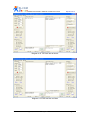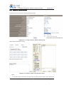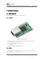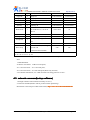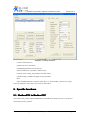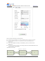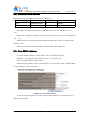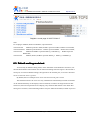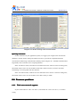
1
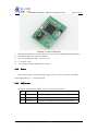
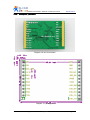
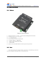
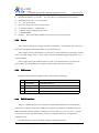
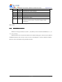
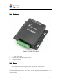
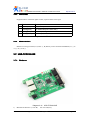
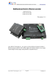
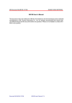
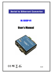
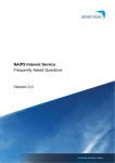
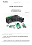
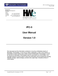
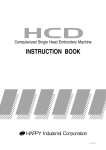
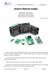
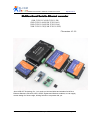
Multifunctional serial to Ethernet module user manual
http://en.usr.cn
Multifunctional Serial to Ethernet converter
(USR-TCP232-E)(USR-TCP232-ED)
(USR-TCP232-400)(USR-TCP232-401)
(USR-TCP232-500)(USR-TCP232-504)
(USR-TCP232-52E)(USR-TCP232-52PE)
File version: V1.3.2
Jinan USR IOT Technology Co., Ltd. works on LAN and WAN and wireless for MCU to
Ethernet Solutions, Ethernet, WIFI, GPRS, Zigbee and Wireless modules, we can supply
custom design for those usage, looking forward to cooperate with you.
Jinan USR IOT Technology Co., Ltd
Page1//9
[email protected]
Multifunctional serial to Ethernet module user manual
http://en.usr.cn
Contents
Multifunctional Serial to Ethernet converter..................................................................................... 1
1. Introduction...................................................................................................................................5
1.1. Overview........................................................................................................................... 5
1.2 Features............................................................................................................................... 5
1.2. Applications.......................................................................................................................6
1.3. Order information.............................................................................................................. 6
1.4. Electrical characteristics.................................................................................................... 7
2. Work Mode................................................................................................................................... 8
2.1. Block diagram....................................................................................................................8
2.2. UDP mode..........................................................................................................................8
2.3. TCP Client mode............................................................................................................... 9
2.4. UDP Server mode............................................................................................................ 10
2.5. TCP Server mode............................................................................................................. 11
2.6. Httpd Client mode............................................................................................................12
2.7. TCP Auto mode............................................................................................................... 14
2.8. WEB to Serial mode........................................................................................................ 16
3. Hardware interface:.....................................................................................................................17
3.1. USR-TCP232-E............................................................................................................... 17
3.1.1. Hardware............................................................................................................... 17
3.1.2. Power.....................................................................................................................17
3.1.3. LED status............................................................................................................. 18
3.1.4. Serial(TTL) interface.............................................................................................18
3.2. USR-TCP232-ED............................................................................................................ 18
3.2.1. Hardware............................................................................................................... 18
3.2.2. Power.....................................................................................................................19
3.2.3. LED status............................................................................................................. 19
3.2.4. Serial(TTL) interface.............................................................................................20
3.3. USR-TCP232-400............................................................................................................22
3.3.1. Hardware............................................................................................................... 22
3.3.2. Power.....................................................................................................................22
3.3.3. LED status............................................................................................................. 23
3.3.4. RS232 interface..................................................................................................... 23
3.3.5. RS485/RS422 interface.................................................................................... 24
3.4. USR-TCP232-401............................................................................................................24
3.4.1. Hardware............................................................................................................... 24
3.4.2. Power.....................................................................................................................25
3.4.3. LED status............................................................................................................. 25
3.4.4. RS232 interface..................................................................................................... 25
Jinan USR IOT Technology Co., Ltd
Page2//9
[email protected]
Multifunctional serial to Ethernet module user manual
http://en.usr.cn
3.4.5. RS485 interface................................................................................................. 26
3.5. USR-TCP232-500............................................................................................................26
3.5.1. Hardware............................................................................................................... 26
3.5.2. Power.....................................................................................................................27
3.5.3. LED status............................................................................................................. 27
3.5.4. RS232 interface..................................................................................................... 27
3.5.5. RS485/RS422 interface.................................................................................... 28
3.6. USR-TCP232-504............................................................................................................29
3.6.1. Hardware............................................................................................................... 29
3.6.2. Power.....................................................................................................................29
3.6.3. LED status............................................................................................................. 30
3.6.4. RS485 interface................................................................................................. 30
3.7. USR-TCP232-52E........................................................................................................... 30
3.7.1. Hardware............................................................................................................... 30
3.7.2. Power.....................................................................................................................31
3.7.3. LED status............................................................................................................. 33
3.7.4. RS232 interface..................................................................................................... 33
3.7.5. RS485 interface................................................................................................. 33
3.7.6. RJ45 interface.................................................................................................... 34
3.8. USR-TCP232-52PE.........................................................................................................34
3.8.1. Hardware............................................................................................................... 34
3.8.2. Power.....................................................................................................................34
3.8.3. LED status............................................................................................................. 34
3.8.4. RS232 interface..................................................................................................... 35
3.8.5. RS485 interface................................................................................................. 35
3.8.6. RJ45 interface.................................................................................................... 35
3.9. RJ45 interface.................................................................................................................. 35
3.10. Reload............................................................................................................................36
4. Paramters configuration.............................................................................................................. 36
4.1. Web page......................................................................................................................... 36
4.2. Serial port........................................................................................................................ 36
4.3. network command(setup software)..................................................................................37
5. Specific functions........................................................................................................................38
5.1. Hardware flow control..................................................................................................... 38
5.2. User MAC address...........................................................................................................39
5.3. Firmupdate.......................................................................................................................40
6. Module USES............................................................................................................................. 42
6.1. Hardware connection....................................................................................................... 42
6.2. Login................................................................................................................................43
6.3. Default working mode test...............................................................................................45
6.4. Common questions.......................................................................................................... 46
6.4.1. Work across network segment............................................................................... 46
6.4.2. Ping is OK but can not open web pages................................................................ 47
Jinan USR IOT Technology Co., Ltd
Page3//9
[email protected]
Multifunctional serial to Ethernet module user manual
http://en.usr.cn
6.4.3. After firm update, can not open web page............................................................. 47
6.4.4. When connection established, server received serval chars.................................. 47
6.4.5. Every serval seconds, module reconnect............................................................... 48
7. Contact us....................................................................................................................................49
8. Modified history..........................................................................................................................50
Jinan USR IOT Technology Co., Ltd
Page4//9
[email protected]
Multifunctional serial to Ethernet module user manual
http://en.usr.cn
1. Introduction
1.1. Overview
The USR-TCP232-E45 is an intelligent plug-and-play RS232 to Ethernet adapter that
enables any device or machine with a serial port, to become Ethernet network and
Internet enabled. Go from Ethernet to serial with the USR-TCP232-E45. It features a
powerful built-in device server, so you can access your serial device from anywhere in the
world over internet! The USR-TCP232-E45 is easily configured via Ethernet, and can
also be set up through the serial port and web pages.
We Provide Network products and the best service to our customers.
• Chips • Modules • Software • Products
1.2 Features
1.
New Cortex-M3 kernel, industrial working temperature range, elaborate optimization
TCPIP protocol stack, stable and reliable.
2.
A RS232 port, can set COM port and working mode independently, work
independently, support RTS/CTS hardware flow control.
3.
A RS232/RS485 compatible port, auto adaptation.
4.
RS232 and RS485 can be used together, work independently, distinguish the
connected serial port via port number.
5.
Auto-MDI/MIDX function, discretionarily connect cross-over or direct network cable,
automatic switching.
6.
Support TCP Server, TCP Client, UDP, UDP Server, HTTPD Client various of work
modes.
7.
Support virtual serial work way, provide corresponding software.
8.
Serial port highest baud rate from 110bps to 1024000bps(COM0 only max
256000bps).
9.
wide voltage input, more applications.
10. Support DHCP automatically access IP, can inquire the facility within network
through the UDP broadcast protocol.
11. Supply the protocol for VIP customers, can integrate parameter seting function to
users’ software applications.
12. Provide PC TCP/IP SOCKET programming example, VB, C++, Delphi, Android, IOS.
13. The built-in web page, also parameter setting via web, can customize web pages for
users.
14. Can also set via UDP, provide the set up protocol and software source code.
15. Reload button, a key restore default Settings.
Jinan USR IOT Technology Co., Ltd
Page5//9
[email protected]
Multifunctional serial to Ethernet module user manual
http://en.usr.cn
16. RJ45 status indicator light, RJ45 interface built-in isolation transformer, 2 KV
isolation.
17. The global only MAC address bought from IEEE, the user can define MAC address
(please state when you make order).
18. Support upgrade firmware via network.
19. Support IP and domain name at the same time
20. Support up to 4 link from client when act as TCP Server, send and receive data with
id.
21. Can modify MAC address you wanted.
22. Can modify http server port for module built-in http server.
23. Support Keepalive.
1.2. Applications
�
�
�
�
�
�
�
�
�
�
�
Fire and Security Panels
Vending Machines
Point of Sale Terminals
Remote equipment management
IT management services
Access Control
Industrial Control
Home Automation
Instrumentation
Building Control
Power Management
1.3. Order information
Type
Part Numbers
Electric interface
Serial to Ethernet Converter
USR-TCP232-E
2 * TTL232
Serial to Ethernet Converter
USR-TCP232-ED
3 * TTL232
Serial to Ethernet Converter
USR-TCP232-400
1 * RS232, 1 * RS485/RS422
Serial to Ethernet Converter
USR-TCP232-401
1 * RS232, 1 * RS485
Serial to Ethernet Converter
USR-TCP232-500
2 * RS232, 1 * RS485/RS422
Serial to Ethernet Converter
USR-TCP232-504
3 * RS485
Serial to Ethernet Converter
USR-TCP232-52E
2 * RS232, 1 * RS485, 2 * RJ45
Serial to Ethernet Converter
USR-TCP232-52PE
2 * RS232, 1 * RS485, 2 * RJ45(POE)
Diagram 1-1 Order information
Note:
For webpages: PORT0, PORT1 and PORT2, represent below:
Jinan USR IOT Technology Co., Ltd
Page6//9
[email protected]
Multifunctional serial to Ethernet module user manual
TCP232-E:
http://en.usr.cn
PORT0 represent UART0, PORT1 represent UART1, PORT2 not available in
hardware;
TCP232-ED:
PORT0 represent UART0, PORT1 represent UART1, PORT2 represent
UART2;
TCP232-400/401: PORT0 represent RS232,PORT1 represent RS485,PORT2 not available;
TCP232-500:
PORT0 and PORT1 represent RS232_0 and RS232_1,PORT2 represent
RS485/422;
TCP232-504:
PORT0, PORT1, PORT2 represent RS485_0、RS485_1 and RS485_2;
TCP232-52E/52PE:PORT0 and PORT1 represent RS232_0 and RS232_1,PORT2 represent
RS485
1.4. Electrical characteristics
DC Power Supply Voltage:
Two DC Voltage can be choose(for USR-TCP232-E, others see Hard interface)
VCC:type: 3.3V, min: 3.15,max: 3.45 V
VDD:type: 5V, min: 4.5V,max: 5.5V
Operating supply current : Max: 180 MA
Operating Temperature: -40~85 °C
Storage temperature: -40~85 °C
Jinan USR IOT Technology Co., Ltd
Page7//9
[email protected]
Multifunctional serial to Ethernet module user manual
http://en.usr.cn
2. Work Mode
2.1. Block diagram
Take USR-TCP232-E for example, show demo application of module USR-TCP232-E.
power
Ethernet
TTL
Serial to Ethernet
Converter
User
device
U S R -T C P 2 3 2 -E
Diagram 2-1 USR-TCP232-E application demo
2.2. UDP mode
When in UDP mode, after power on, module listen on specific port.
1. Module listen a UDP port
1.PC listen a UDP port
2. Data transfer With out connection, only data packet
MCU
5 1 ,A V R ,P I C ,A R M
R S 232
Ethernet
Module work at UDP mode
Diagram 2-2 UDP mode
When received data from this udp port, send it to serial port;otherwise, when data is received
from serial port, send it to ethernet.
The assist software can be download from link below:
http://www.usr.so/Download/121.html
Jinan USR IOT Technology Co., Ltd
Page8//9
[email protected]
Multifunctional serial to Ethernet module user manual
http://en.usr.cn
Diagram 2-3 UDP mode communication test
Note:
1)
2)
local port and remote port can be different.
Max UDP send length(ethernet to serial) is 1472 bytes. If you want to send more than 1472
Bytes, please div it into shorter packet.
2.3. TCP Client mode
Open web pages and config module to
Telent Mode:
TCP Client
Remote port number: 23
Telnet Server Addr:
192.168.0.131
Jinan USR IOT Technology Co., Ltd
Page9//9
[email protected]
Multifunctional serial to Ethernet module user manual
http://en.usr.cn
Diagram 2-4 TCP Client mode
Use USR-TCP232-Test,
Diagram 2-5 TCP Client communication test
2.4. UDP Server mode
Like the socket UDP server in pc API. Many to one data transfer supported, the data
from uart/232/485 part will be transformed to the last UDP packet’s address.
Here show 2 UDP client communicate with server, server send data to the last client
communicates with it.
Jinan USR IOT Technology Co., Ltd
Page10//9
[email protected]
Multifunctional serial to Ethernet module user manual
http://en.usr.cn
Diagram 2-6 Client 1 <-> server
Diagram 2-7 Client 2 <-> server
2.5. TCP Server mode
TCP Server mode have 2 parameters: max link number and link type
1. max link number: 1 ~ 4;
2. Link type: typical, completely transparent, send data to all client;
Jinan USR IOT Technology Co., Ltd
Page11//9
[email protected]
Multifunctional serial to Ethernet module user manual
http://en.usr.cn
extend1, communicate with id, otherwise abandon;
extend2, communicate with id, otherwise send to all client.
For link type extended 1 and extended 2:
When receive data from ethernet, module will send data to serial port with head ‘I’
‘N’ ,followed by data. ’I’ represent incoming data, ‘N’ represent client index.
When user MCU want send data to module serial port, start with head ‘O’ ‘N’ data... ‘O’
represent send out, ‘N’ represent which client.
When new TCP connection incoming, module will send ‘C’ ‘N’ ‘M’ to serial port, indicating
that there is current link ‘N’ accessed, total link number ‘M’.
When link number have exceed maximum, new link requirment will lead to message ‘F’ ‘F’.
When disconnect, module will send ‘D’ ‘N’ ‘M’, represent current link N is delete, left link
M.
Note:
serial data need to be sent in one package to module.
Diagram 2-8 web page configuration
2.6. Httpd Client mode
This function is easier used for web page developer. We establish one web server page, add
this:
[<?php echo $_GET['data']; ?>]
Means we can GET data from HTTP client’s request. Open this URL:
www.usr.cn/1.php?data=12345, the web page is downbelow, we can see that the web server have
got the data(12345),
Jinan USR IOT Technology Co., Ltd
Page12//9
[email protected]
Multifunctional serial to Ethernet module user manual
http://en.usr.cn
Diagram 2-9 Request www.usr.cn/1.php? and upload data
Then we take another way, set USR-TCP232-E module Work mode HTTPD Client, Target
address www.usr.cn, Target port 80,
Diagram 2-10 config HTTPD Client
Jinan USR IOT Technology Co., Ltd
Page13//9
[email protected]
Multifunctional serial to Ethernet module user manual
http://en.usr.cn
Diagram 2-11 module act as HTTPD Client
Note.
HTTPD Client based on TCP Client.
2.7. TCP Auto mode
When power on, module work as TCP Server, listen on local port, but if there is data received
from serial port before any connection, module will try to connect remote IP and port as TCP
Client.
Jinan USR IOT Technology Co., Ltd
Page14//9
[email protected]
Multifunctional serial to Ethernet module user manual
http://en.usr.cn
Diagram 2-12 TCP Auto act as Server
Diagram 2-13 TCP Auto act as Client
Jinan USR IOT Technology Co., Ltd
Page15//9
[email protected]
Multifunctional serial to Ethernet module user manual
http://en.usr.cn
2.8. WEB to Serial mode
Communication mode between serial port and web pages.
Diagram 2-14 config module to WEB to Serial mode
Select Telnet mode Web to Serial,
Diagram 2-15 WEB to Serial communication demo
Note:
1、received window show data only when click on “read” button or select “Auto read”button.
Jinan USR IOT Technology Co., Ltd
Page16//9
[email protected]
Multifunctional serial to Ethernet module user manual
http://en.usr.cn
2、whether WEB to Serial mode or not, send web data to serial always work.
3. Hardware interface:
3.1. USR-TCP232-E
About the new PCB libraries file, we can load from website.
3.1.1. Hardware
Diagram 3-1 USR-TCP232-E
1)
2)
Mechanical dimesion: (L×W×H): 55×30×23.2(mm) including RJ45 and connector;
PCB dimension(L×W): 50.4×30.0(mm);
3)
5V 3.3V double power input,choose 1 input
1)
2)
2 * serial(2 * TTL)
TTL serial port support hardware flow control
3.1.2. Power
Power supply socket, The input voltage range 3.3V or 5V, current 150 MA. We default
supply high quality 5 V / 1 A power adapter.
Jinan USR IOT Technology Co., Ltd
Page17//9
[email protected]
Multifunctional serial to Ethernet module user manual
http://en.usr.cn
3.1.3. LED status
Except for Link and Data of RJ45, there is one work LED interface
ID
name
Description
Just interface, have no LED on module,
If you needed, take this pin with LED and 510 ohm
resistor to GND.
See Pin8 for further explantion.
1
Work
2
Link(green)
On RJ45, when ethernet link established, on.
3
Data(yellow)
On RJ45, wnen ethernet data communicate, twinkle.
Diagram 3-2 LED definition
3.1.4. Serial(TTL) interface
The serial port is TTL level (2 * TTL serial port, can be directly connected to MCU).
number
name
Description
1
TXD0
Uart0 transmit data pin
2
RXD0
Uart0 receive data pin
3
CTS0
Uart0 RS232 clear to send
4
RTS0
Uart0 require to send
5
RXD1
Uart1 receive data pin
6
TXD1
Uart1 transmit data pin
Diagram 3-3 connector interface(include uart0 and uart1)
3.2. USR-TCP232-ED
3.2.1. Hardware
Jinan USR IOT Technology Co., Ltd
Page18//9
[email protected]
Multifunctional serial to Ethernet module user manual
http://en.usr.cn
1)
2)
Diagram 3-4 USR-TCP232-ED
Mechanical dimesion: (L×W×H): 44.45×31.75×15.4(mm) including RJ45 and connector;
PCB dimension(L×W): 44.45×31.75(mm);
3)
5V 3.3V double power input,choose 1 input
4)
5)
3 * serial(3 * TTL)
TTL serial port support hardware flow control
3.2.2. Power
Power supply socket, The input voltage range 3.3V or 5V, current 150 MA. We default
supply high quality 5 V / 1 A power adapter.
3.2.3. LED status
Except for Link and Data of RJ45, there is one work LED interface
ID
name
Description
1
Work
Twinkle every 1 seconds
2
Link(green)
On RJ45, when ethernet link established, on.
3
Data(yellow)
On RJ45, wnen ethernet data communicate, twinkle.
Diagram 3-5 LED definition
Jinan USR IOT Technology Co., Ltd
Page19//9
[email protected]
Multifunctional serial to Ethernet module user manual
http://en.usr.cn
3.2.4. Serial(TTL) interface
Diagram 3-6 view from bottom
Diagram 3-7 pin diagram
Jinan USR IOT Technology Co., Ltd
Page20//9
[email protected]
Multifunctional serial to Ethernet module user manual
http://en.usr.cn
The serial port is TTL level (3 * TTL serial port, can be directly connected to MCU).
number
name
Description
1
ETH_TX+
Ethernet TX+
2
ETH_TX-
Ethernet TX-
3
ETH_RX+
Ethernet RX+
4
ETH_RX-
Ethernet RX-
5
LED_DATA
Ethernet Data
6
TXD0
Uart0 transmit data pin
7
RXD0
Uart0 receive data pin
8
485_en(RTS0)
RS485 enable(Uart0 require to send)
9
Reload
Restore to factory
10
RST
reset
11
GND
ground
12
GND
ground
13
+5V
+5V power
14
+5V
+5V power
15
LED_LINK
Ethernet link
16
+3.3V
+3.3V power
17
RXD1
Uart1 receive data pin
18
TXD1
Uart1 transmit data pin
19
RXD2
Uart2 receive data pin
20
TXD2
Uart2 transmit data pin
21
CTS0
Uart0 RS232 clear to send
22
RTS1
Uart1 require to send
23
CTS1
Uart1 RS232 clear to send
Diagram 3-8 connector interface(include uart0, uart1, uart3)
Note:
1)
Uart2 have no RTS and CTS
Jinan USR IOT Technology Co., Ltd
Page21//9
[email protected]
Multifunctional serial to Ethernet module user manual
http://en.usr.cn
3.3. USR-TCP232-400
3.3.1. Hardware
Diagram 3-9 USR-TCP232-400
1)
2)
3)
Mechanical dimesion: (L×W×H): 90×84×25(mm) including RJ45 and connector;
PCB dimension(L×W): 80.3×50.3(mm);
+5 ~ +18V power input;
4)
DC power plug, 5.08 connector power input
5)
6)
7)
8)
2 * serial(1 * RS232, 1 * RS485/422)
1 * RS232 support hardware flow control
1 * RS485/RS422
Specific: PIN 9 of the RS232 DB9 can connect to power for special uses.
3.3.2. Power
This system has three power supply interface, a power hub, a 5.08 terminal, pin 9 of the two
serial com (through the PCB jumper short circuit, default closed).
Jinan USR IOT Technology Co., Ltd
Page22//9
[email protected]
Multifunctional serial to Ethernet module user manual
http://en.usr.cn
Power supply socket, outer diameter 5.5 mm inner 2.1 mm standard size, inside plus, outside
minus. The input voltage range 5 ~ 18 V, current 150 MA. We default supply high quality 5 V / 1
A power adapter.
Power supply socket, the terminal and pin 9 of the com, mutual unicom, can choose one
power supply in, and another power supply out, better adapt to the use environment.
3.3.3. LED status
Equipment have 4 indicator lights in total, sequence from left to right.
ID
Name
Description
1
Power(red)
Bright after power on
2
Work(green)
Flash at work
3
Link(green)
In RJ45 port, bright after network connection
4
Data(yellow)
In RJ45 port, flash if there are datas on network
Diagram 3-10 LED definition
3.3.4. RS232 interface
The serial port is male (needl), RS232 level (can be directly connected to computer serial),
part of RS232 pin sequences consistent to computer COM port. When connected with the
computer, we need to use cross cable (2-3 cross, 7-8 cross, 5-5 direct, 7-8 can don’t connect, but
musn’t direcly connect to computer. Otherwise, it might lead to irregularly work).
The DB9 interface contains the RS232, RS485 and RS422 interfaces.
Number
RS232
RS485
RS422
Description
1
-
B(-)
TX-
2
RXD
-
-
RS232 device receive data pin
3
TXD
-
-
RS232 device transmit data pin
4
-
-
RX-
RS422 receive minus
5
GND
GND
GND
Signal ground
6
-
A(+)
TX+
RS485 plus or RS422 transmit plus
7
RTS
-
-
RS232 require to send
8
CTS
-
-
RS232 clear to send
9
-
-
RX+
RS422 receive plus
RS485 minus or RS422 transmit minus
Diagram 3-11 DB9 interface
Note: this DB9 interface include RS232 and RS485/RS422.
Jinan USR IOT Technology Co., Ltd
Page23//9
[email protected]
Multifunctional serial to Ethernet module user manual
3.3.5.
http://en.usr.cn
/RS422 interface
RS485
RS485/RS422
RS485 two wirings terminal, A (DATA +), B (DATA), when connected with RS485, A (+) to
A (+), B (-) to B (-).
RS422 interface also connected to RS232 nine needles binding post. The device have RS232
and RS485 interface, but can only use one in a time, autoadaptation, connect as RS485 is RS485
function, connect as RS422 wiring is RS422 function.
3.4. USR-TCP232-401
3.4.1. Hardware
Diagram 3-12 USR-TCP232-401
1)
2)
3)
Mechanical dimesion: (L×W×H): 90×84×25(mm) including RJ45 and connector;
PCB dimension(L×W): 80.3×50.3(mm);
+5 ~ +18V power input;
4)
DC power plug, 5.08 connector power input
5)
6)
7)
2 * serial(1 * RS232, 1 * RS485)
1 * RS232 support hardware flow control
1 * RS485
Jinan USR IOT Technology Co., Ltd
Page24//9
[email protected]
Multifunctional serial to Ethernet module user manual
http://en.usr.cn
3.4.2. Power
This system has three power supply interface, a power hub, a 5.08 terminal.
Power supply socket, outer diameter 5.5 mm inner 2.1 mm standard size, inside plus, outside
minus. The input voltage range 5 ~ 18 V, current 150 MA. We default supply high quality 5 V / 1
A power adapter.
3.4.3. LED status
Equipment have 4 indicator lights in total, sequence from left to right.
ID
Name
Description
1
Power(red)
Bright after power on
2
Work(green)
Flash at work
3
Link(green)
In RJ45 port, bright after network connection
4
Data(yellow)
In RJ45 port, flash if there are datas on network
Diagram 3-13 LED definition
3.4.4. RS232 interface
The serial port is male (needl), RS232 level (can be directly connected to computer serial),
part of RS232 pin sequences consistent to computer COM port. When connected with the
computer, we need to use cross cable (2-3 cross, 7-8 cross, 5-5 direct, 7-8 can don’t connect, but
musn’t direcly connect to computer. Otherwise, it might lead to irregularly work).
The DB9 interface contains the RS232, RS485 and RS422 interfaces.
Number
RS232
Description
1
-
2
RXD
RS232 device receive data pin
3
TXD
RS232 device transmit data pin
4
-
5
GND
6
-
7
RTS
RS232 require to send
8
CTS
RS232 clear to send
9
-
-
Signal ground
-
-
Diagram 3-14 DB9 interface
Jinan USR IOT Technology Co., Ltd
Page25//9
[email protected]
Multifunctional serial to Ethernet module user manual
3.4.5.
http://en.usr.cn
RS485 interface
RS485 two wirings terminal, A (DATA +), B (DATA), when connected with RS485, A (+) to
A (+), B (-) to B (-).
Diagram 3-15 choose RS485 for 401 if you want to use RS485
3.5. USR-TCP232-500
3.5.1. Hardware
Jinan USR IOT Technology Co., Ltd
Page26//9
[email protected]
Multifunctional serial to Ethernet module user manual
http://en.usr.cn
1)
Diagram 3-16 USR-TCP232-500
Mechanical dimesion: (L×W×H): 155×100×34(mm), including RJ45 and connector
2)
3)
PCB dimension(L×W): 130.5×90.2(mm);
+5 ~ +48V power input
4)
DC power plug, 5.08 connector power input
5)
6)
7)
8)
3 * serial(2 * RS232, 1 * RS485/422)
2 * RS232 support hardware flow control
1 * RS485/RS422
Specific: PIN 9 of the RS232 DB9 can connect to power for special uses.
3.5.2. Power
This system has three power supply interface, a power hub, a 5.08 terminal, pin 9 of the two
serial com (through the PCB jumper short circuit, default closed).
Power supply socket, outer diameter 5.5 mm inner 2.1 mm standard size, inside plus, outside
minus. The input voltage range 5 ~ 48 V, current 150 MA. We default supply high quality 5 V / 1
A power adapter.
Power supply socket, the terminal and pin 9 of the com, mutual unicom, can choose one
power supply in, and another power supply out, better adapt to the use environment.
3.5.3. LED status
Equipment have 4 indicator lights in total, sequence from left to right.
ID
Name
Description
1
Power(red)
Bright after power on
2
Work(green)
Flash at work
3
Link(green)
In RJ45 port, bright after network connection
4
Data(yellow)
In RJ45 port, flash if there are datas on network
Diagram 3-17 LED definition
3.5.4.
RS232 interface
It have 2 * RS232 interface. The serial port is male (needl), RS232 level (can be directly
connected to computer serial), part of RS232 pin sequences consistent to computer COM port.
When connected with the computer, we need to use cross cable (2-3 cross, 7-8 cross, 5-5 direct,
7-8 can don’t connect, but musn’t direcly connect to computer. Otherwise, it might lead to
irregularly work).
The DB9 interface contains the RS232, RS485 and RS422 interfaces.
Jinan USR IOT Technology Co., Ltd
Page27//9
[email protected]
Multifunctional serial to Ethernet module user manual
http://en.usr.cn
Number
name
Description
2
RXD
RS232 device receive data pin
3
TXD
RS232 device transmit data pin
5
GND
Signal ground
7
RTS
RS232 require to send
8
CTS
RS232 clear to send
9
VCC
Default not used. there is one pad jumper, default
disconnect, when connect, it can power supply outside
serial device.
Diagram 3-18 DB9 interface
Note: none
3.5.5.
/RS422 interface
RS485
RS485/RS422
RS485 two wirings terminal, A (DATA +), B (DATA), when connected with RS485, A (+) to
A (+), B (-) to B (-).
RS422 interface also connected to RS232 nine needles binding post. The device have RS232
and RS485 interface, but can only use one in a time, autoadaptation, connect as RS485 is RS485
function, connect as RS422 wiring is RS422 function.
Jinan USR IOT Technology Co., Ltd
Page28//9
[email protected]
Multifunctional serial to Ethernet module user manual
http://en.usr.cn
3.6. USR-TCP232-504
3.6.1. Hardware
1)
2)
3)
Diagram 3-19 USR-TCP232-504
Mechanical dimesion: (L×W×H)95×85×25(mm), including RJ45 and connector;
PCB dimension(L×W): 80×50(mm);
+5 ~ +18V power input;
4)
DC power plug, 5.08 connector power input
5)
3 * serial(3 * RS485)
3.6.2. Power
This system has three power supply interface, a power hub, a 5.08 terminal.
Power supply socket, outer diameter 5.5 mm inner 2.1 mm standard size, inside plus, outside
minus. The input voltage range 5 ~ 48 V, current 150 MA. We default supply high quality 5 V / 1
A power adapter.
Jinan USR IOT Technology Co., Ltd
Page29//9
[email protected]
Multifunctional serial to Ethernet module user manual
http://en.usr.cn
3.6.3. LED status
Equipment have 4 indicator lights in total, sequence from left to right.
ID
Name
Description
1
Power(red)
Bright after power on
2
Work(green)
On PCB board(can not be seen)
3
Link(green)
In RJ45 port, bright after network connection
4
Data(yellow)
In RJ45 port, flash if there are data on network
Diagram 3-20 LED definition
3.6.4.
RS485 interface
RS485 two wirings terminal, A (DATA +), B (DATA), when connected with RS485, A (+) to
A (+), B (-) to B (-).
3.7. USR-TCP232-52E
3.7.1. Hardware
1)
Diagram 3-21 USR-TCP232-52E
Mechanical dimesion: (L×W×H): 103×105×28(mm);
Jinan USR IOT Technology Co., Ltd
Page30//9
[email protected]
Multifunctional serial to Ethernet module user manual
http://en.usr.cn
2)
3)
PCB dimension(L×W): 100×76(mm);
DC+5 ~ +28V power input;
4)
DC power plug, 3.81connector power input;
5)
6)
7)
8)
9)
3 * serial(2 * RS232, 1 * RS485);
2 * RS232 support hardware flow control;
1 * RS485;
Specific: PIN 9 of the RS232 DB9 can connect to power for special uses;
2*RJ45 , 10/100M adaptive,you can take advantage of the free foot cable to achieve 5-28V
power supply network port .
Diagram 3-22 PCB inches
3.7.2. Power
This system has four power supply interface, a power hub, a 3.81terminal, pin 9 of the two
serial com (through the PCB jumper short circuit, default closed) and RJ45.
�
Power supply socket, outer diameter 5.5 mm inner 2.1 mm standard size, inside plus, outside
minus. The input voltage range 5 ~ 28 V . We default supply high quality 5 V / 1 A power
adapter.
�
3.81 pitch terminal blocks, terminal external customers through the introduction of 5-28V
power supply line.
Jinan USR IOT Technology Co., Ltd
Page31//9
[email protected]
Multifunctional serial to Ethernet module user manual
�
http://en.usr.cn
Power supply socket, the terminal and pin 9 of the com, mutual unicom, can choose one
power supply in, and another power supply out, better adapt to the use environment.
�
Network power, you can use an external network cable to supply power to the module, power
supply range of 5-28V.
Jinan USR IOT Technology Co., Ltd
Page32//9
[email protected]
Multifunctional serial to Ethernet module user manual
http://en.usr.cn
3.7.3. LED status
Equipment have 5 indicator lights in total, sequence from left to right.
ID
Name
Description
1
Power(red)
Bright after power on
2
Work(green)
Flash at work
3
Link1(green)
In RJ45 1 port, bright after network connection
4
Link2(green)
In RJ45 2 port, bright after network connection
5
Link3(green)
bright after network connection module
Diagram 3-23
3.7.4.
LED definition
RS232 interface
It have 2 * RS232 interface. The serial port is male (needl), RS232 level (can be directly
connected to computer serial), part of RS232 pin sequences consistent to computer COM port.
When connected with the computer, we need to use cross cable (2-3 cross, 7-8 cross, 5-5 direct,
7-8 can don’t connect, but musn’t direcly connect to computer. Otherwise, it might lead to
irregularly work).
The DB9 interface contains the RS232.
Number
name
Description
2
RXD
RS232 device receive data pin
3
TXD
RS232 device transmit data pin
5
GND
Signal ground
7
RTS
RS232 require to send
8
CTS
RS232 clear to send
9
VCC
Default not used. there is one pad jumper, default
disconnect, when connect, it can power supply outside
serial device.
Diagram 3-24
3.7.5.
DB9 interface
RS485 interface
RS485 two wirings terminal, A (DATA +), B (DATA), when connected with RS485, A (+) to
A (+), B (-) to B (-).
Jinan USR IOT Technology Co., Ltd
Page33//9
[email protected]
Multifunctional serial to Ethernet module user manual
http://en.usr.cn
3.7.6. RJ45 interface
With two network interfaces, can be achieved hand in hand communications equipment.
While supporting DC5-28V POE power supply network cable, reducing the power supply wiring.
3.8. USR-TCP232-52PE
3.8.1. Hardware
1)
2)
3)
Mechanical dimesion: (L×W×H): 103×105×28(mm);
PCB dimension(L×W): 100×76(mm);
DC+5 ~ +28V power input;
4)
DC power plug, 3.81connector power input;
5)
6)
7)
8)
3 * serial(2 * RS232, 1 * RS485);
2 * RS232 support hardware flow control;
1 * RS485;
2*RJ45 , 10/100M adaptive,you can take advantage of the free foot cable to achieve 5-28V
power supply network port .
3.8.2. Power
Network power supply standard 48V POE.
3.8.3. LED status
Equipment have 5 indicator lights in total, sequence from left to right.
ID
Name
Description
1
Power(red)
Bright after power on
2
Work(green)
Flash at work
3
Link1(green)
In RJ45 1 port, bright after network connection
4
Link2(green)
In RJ45 2 port, bright after network connection
5
Link3(green)
bright after network connection module
Diagram 3-25
Jinan USR IOT Technology Co., Ltd
LED definition
Page34//9
[email protected]
Multifunctional serial to Ethernet module user manual
3.8.4.
http://en.usr.cn
RS232 interface
It have 2 * RS232 interface. The serial port is male (needl), RS232 level (can be directly
connected to computer serial), part of RS232 pin sequences consistent to computer COM port.
When connected with the computer, we need to use cross cable (2-3 cross, 7-8 cross, 5-5 direct,
7-8 can don’t connect, but musn’t direcly connect to computer. Otherwise, it might lead to
irregularly work).
The DB9 interface contains the RS232.
Number
name
Description
2
RXD
RS232 device receive data pin
3
TXD
RS232 device transmit data pin
5
GND
Signal ground
7
RTS
RS232 require to send
8
CTS
RS232 clear to send
Diagram 3-26
3.8.5.
DB9 interface
RS485 interface
RS485 two wirings terminal, A (DATA +), B (DATA), when connected with RS485, A (+) to
A (+), B (-) to B (-).
3.8.6. RJ45 interface
Two network communication interface, accepting 1,2,3,6 and 4,5,7,8 standard in two
methods PSE.
3.9. RJ45 interface
Internet access port connection, module network interface is 10 M / 100 M adaptive, support
AUTO MDI/MDIX, can discretionarily connect cross-over or direct network cable. That is to say,
you can use direct cable to connect with computer or test.
Pin
Name
Description
1
TX+
Transceiver Data+
2
TX-
Transceiver Data-
3
RX+
Receive Data+
4
n/c
Not connected
5
n/c
Not connected
6
RX-
Receive Data-
Jinan USR IOT Technology Co., Ltd
Page35//9
[email protected]
Multifunctional serial to Ethernet module user manual
7
n/c
Not connected
8
n/c
Not connected
http://en.usr.cn
Diagram 3-27 RJ45 interface
3.10. Reload
This button is used to restore factory settings. Press the button and power on, then free this
Reload button, device will be factory settings.
Default settings main parameters as follows
Address type:
static IP
Static IP Address: 192.168.0.7
User name:
admin
password:
admin
Module name: USR-TCP232-E
Using web pages can also restore default settings.
Diagram 3-28 restore defaults through web pages
4. Paramters configuration
4.1. Web page
Usually, this series of TCP232 module is configured through web pages.
4.2. Serial port
After module already power on, press Reload(for USR-TCP232-E, pull Reload low), module
will go in Serial config mode(in this mode we can config paramters through serial command), then
module serial port 0 will switch to 9600, 8, n, 1, and send char ‘U’, indicating that module already
in serial config mode.
after config complete, module will send ‘K’ out, indicating config success;
Verify error will be ‘E’ and correct verify byte.
Free Reload(for USR-TCP232-E, pull Reload high), module will save paramters and reboot,
config take effect.
name
Byte
Jinan USR IOT Technology Co., Ltd
Description
Page36//9
example
Hex(low front)
[email protected]
Multifunctional serial to Ethernet module user manual
head
2
Head(55 BA/55 C1/55 C2)
Target IP
4
Target IP
Target port
2
Module IP
http://en.usr.cn
55 BA
55 BA
192.168.0.201
C9 00 A8 C0
Target port
8234
2A 20
4
Module IP
192.168.0.7
07 00 A8 C0
Module port
2
Module port
20108
8C 4E
gateway
4
Gateway IP
192.168.0.201
C9 00 A8 C0
Work mode
1
1 for TCP Client;0 for UDP; 2
for UDP Server; 3 for TCP
Server
TCP Client
01
Baud rate
3
Serial baud rate
115200
00 C2 01
serial param
1
Databits, stopbits, verifybits
N,8,1
03
Unique ID
3
ID-H, ID-L, ID-type, 0 for no
use
No use
00 00 00
Subnet mask
4
Subnet mask, low front
255.255.255.0
00 FF FF FF
1
Sum verification, from target
ip until end
(sum itself not included)
sum
B9
Sum verify
Total cmd:55 BA C9 00 A8 C0 2A 20 07 00 A8 C0 8C 4E C9 00 A8 C0 01 00 C2 01 03
00 00 00 00 FF FF FF B9
Diagram 4-1 protocol structure and example
Note.
1. Head definition.
55 BA for write Port0,55 BC for read port0;
55 C1 for write Port1,55 C3 for read port1;
55 C2 for write Port2,55 C4for read port2(Port2 only for-500).
2. For further information, see <USR-TCP232-XX config protocol V3.doc>.
4.3. network command(setup software)
1. through software USR-TCP232-E45 Setup V1.0.5.0;
2. Network command(need to ask for protocol before purchasing).
Downbelow is the Setup for USR-TCP232-E45, http://www.usr.so/Download/90.html
Jinan USR IOT Technology Co., Ltd
Page37//9
[email protected]
Multifunctional serial to Ethernet module user manual
http://en.usr.cn
Diagram 4-2 Setup software
(1)click ‘Search Device’;
(2)Select device in search list;
(3)Modified paramters such as static ip;
(4)Click ‘Base Save’, paramters will be saved;
(5)Click ‘Save Config’, the paramters will take effect;
(6)Search again, module will appear in new paramters.
Note.
After modified paramters, need first ‘Base Save’ or ‘Save COMX’, then ‘Save Config’.
If not, the paramters will only be saved, but not take effect.
5. Specific functions
5.1. ModbusRTU to ModbusTCP
The whole series product support ModbusRTU to ModbusTCP. When you use it, you have to
select the protocols, just here:
Jinan USR IOT Technology Co., Ltd
Page38//9
[email protected]
Multifunctional serial to Ethernet module user manual
http://en.usr.cn
Here, the usement and function is presented below.
� Selection None, that indicate we are using Transparent mode, no protocol convertion.
� Selection ModbusTCP, means we use protocol convertion from Modbus RTU to
ModbusTCP.
� In the comm side(RS232 or RS485), it's ModbusRTU protocol , the ethernet side is
ModbusTCP.
� The ethernet side must be a Master, who send query frame first, and the Modbus RTU device
respond with data to the command.
The function acts as below.
ModbusRTU to ModbusTCP
User Device
ModbusRTU
Jinan USR IOT Technology Co., Ltd
T C P 2 3 2 -4 0 1
Page39//9
ModbusTCP
PC
[email protected]
Multifunctional serial to Ethernet module user manual
http://en.usr.cn
5.2. Hardware flow control
RS232 interface support hardware flowcontrol(RTS/CTS)
Pin name
Description
IO type
Operater
RTS
Request to Send
O
module
CTS
Clear to Send
I
Outside device(PC)
Diagram 5-1 Pin description
When RTS = 0, enable the other side to send, at this time, TTL is 0 volt, RS232 is -3V ~
-15V;
When CTS = 0, represent module is enabled to send, at this time, TTL is 0 volt, and RS232 is
-3V ~ -15V;
When the logic is reverse, represent that disable the other side to send or was disabled the
module to send.
When connect with PC’s RS232 interface, we can use the serial cable(cross).
5.3. User MAC address
User MAC address default is 6 bytes of 0xff,that is: FF-FF-FF-FF-FF-FF,
If defaults,use the factory MAC address such as: ac- cf-23-20-fe-3d;
If not, user MAC address will take effect.
When modify this address, insert ‘-’ between bytes, or insert nothing. Click ‘Update Settings’
to save parameters, reset to take effect.
Diagram 5-2 user MAC address
In Current config and status, can see the currently MAC address in use. Diagram below is
using the factory MAC.
Jinan USR IOT Technology Co., Ltd
Page40//9
[email protected]
Multifunctional serial to Ethernet module user manual
http://en.usr.cn
Diagram 5-3 currently MAC in use
5.4. Firmupdate
Use search and config software
to update firmware, only
once for one time, can not cross network segment.
1. Search and select one module
Diagram 5-6 search and select
2. ‘Device’ -> firmware update
Jinan USR IOT Technology Co., Ltd
Page41//9
[email protected]
Multifunctional serial to Ethernet module user manual
http://en.usr.cn
Diagram 5-7 firmware update
Click
to start update progress.
Diagram 5-8 in update progress
3. Update success, click exit.
Jinan USR IOT Technology Co., Ltd
Page42//9
[email protected]
Multifunctional serial to Ethernet module user manual
http://en.usr.cn
Diagram 5-9 success
Note. After update, if can not search module, restore to factory will fix this problem.
6. Module USES
6.1. Hardware connection
For the convenience of use, we designed evaluation board for module USR-TCP232-E, with
the RS232 to TTL conversion circuit, convenient for user communicate with computer.
Here we take USR-TCP232-E for example, The default configuration:
IP address: 192.168.0.7
Subnet mask: 255.255.255.0
The default gateway: 192.168.0.1
Diagram 6-1 IP Address Selection
To test briefly, you can connect the module with computer via network cable, or you can also
connect the module and computer to switch or router at the same time. No need to distinguish
Jinan USR IOT Technology Co., Ltd
Page43//9
[email protected]
Multifunctional serial to Ethernet module user manual
http://en.usr.cn
cross and direct connect cable, the module have automatic switch function. And, change computer
IP to 192.168.0. *, such as 192.168.0.161 we test.
Connect the module serial to computer through TTL to RS232 turn wiring. if you use TTL to
USB turn wiring, please pay attention to the quality of the turn wiring, most low price USB turn
TTL module on market is low quality at present.
Power up, 5 V connect to VDD or 3.3 V connect to VCC, keep the voltage stable, 150 MA
current at least.
power
Ethernet
TTL
User
device
Serial to Ethernet
Converter
U S R -T C P 2 3 2 -E
Diagram 6-2 Application
6.2. Login
Login above IP address http://192.168.0.7 through the browser, you will enter setup web
pages.
User name and password are “admin”, this can be modified when login into the system.
Jinan USR IOT Technology Co., Ltd
Page44//9
[email protected]
Multifunctional serial to Ethernet module user manual
http://en.usr.cn
Diagram 6-3 Login web page
Webpage as follows, PORT2 is not available, 2. TTL(uart0) Settings and 3. TTL(uart1)
Settings respectively corresponding to UART0 and UART1 Settings, 4. Miscellaneous Settings is
used to set some parameters such as module IP and module name.
Jinan USR IOT Technology Co., Ltd
Page45//9
[email protected]
Multifunctional serial to Ethernet module user manual
http://en.usr.cn
Diagram 6-4 web page of USR-TCP232-E
Note:
For webpages: PORT0, PORT1 and PORT2, represent below:
TCP232-E/ED:
PORT0 represent UART0, PORT1 represent UART1, PORT2 not available;
TCP232-400/401: PORT0 represent RS232,PORT1 represent RS485,PORT2 not available;
TCP232-500:
PORT0 and PORT1 represent RS232_0 and RS232_1,PORT2 represent
RS485/422;
TCP232-504:
PORT0, PORT1, PORT2 represent RS485_0、RS485_1 and RS485_2
6.3. Default working mode test
To test briefly in default working mode, on the foundation of the hardware connection, use
the matched software USR-TCP232-Test to make transmitting and receiving test. The left side is
serial port, use software default settings, the right side is the network part, set to TCP Client and
server to be IP 192.168.0.7, port 23.
By default, the two COM port to be set as TCP Server mode, port is 23/26.
This illustration shows the 10 ms two-way simultaneous automatically transmit screenshots.
As the allocated memory of the display control is limited, in order to test large amount of data
transceiver, here will suspend the receive display, only statistical data. Below is the effect after
testing for a few hours, and transmitting millions of bytes. Stable and reliable, without a byte loss.
Jinan USR IOT Technology Co., Ltd
Page46//9
[email protected]
Multifunctional serial to Ethernet module user manual
http://en.usr.cn
Diagram 6-5 default working mode communication
Specially instruction:
For the robustness of your application system, we suggest you using the time out function
(default 0, closed). Such as setting the Telnet Time out, to prevent the complicated internet
circumstances influencing communication stability, and solving the off
lineelink,communication
feign death, TCP connection to be occupied problems.
In the TCP Server mode, if still have no new data transceiver when it is time out setting time,
the module will be active to switch off the client links, release resources, wait for new links,
transmitting or receiving data will clear the time.
In the TCP Client mode, if still have no new data transceiver when it is time out setting time,
the module will be active to switch off the server links and try to relink.
6.4. Common questions
6.4.1. Work across network segment
If your TCP232 device’s IP is 192.168.0.7, and remote PC’s IP is 192.168.1.7, we need to
config.
Jinan USR IOT Technology Co., Ltd
Page47//9
[email protected]
Multifunctional serial to Ethernet module user manual
http://en.usr.cn
Subnet mask of TCP232 device, PC, and router to 255.255.0.0, if not ,the TCP232 module
will not communicate normally.
6.4.2. Ping is OK but can not open web pages
Some possible causes
1. Module is set a static ip and conflicts with another ethernet device.
2. Cross network and false subnet mask .
3. HTTP server port is modified(default 80).
Solutions:
1. Set another static or use DHCP.
2. Set correct subnet mask.
3. Set this port to 80 or open web page with correct port.
6.4.3. After firm update, can not open web page
Reload this module back to factory settings.
6.4.4. When connection established, server received serval chars
Possible causes.
1)
Telnet Protocol use Telnet(usually should be RAW).
2)
Module id type is not 0.
Diagram 6-6 Telnet Protocol
Diagram 6-7 Module id type
Solutions.
1)
Telnet Protocol choose RAW.
2)
Module id type set 0.
Jinan USR IOT Technology Co., Ltd
Page48//9
[email protected]
Multifunctional serial to Ethernet module user manual
http://en.usr.cn
6.4.5. Every serval seconds, module reconnect
Telnet Timeout was set to none 0 value.
Solutions
1)
Give Telnet Timeout 0 or send data before timeout.
Jinan USR IOT Technology Co., Ltd
Page49//9
[email protected]
Multifunctional serial to Ethernet module user manual
http://en.usr.cn
7. Contact us
Company: Jinan USR IOT Technology Co., Ltd
Address: 1-724--728, Huizhan Guoji Cheng, Gaoxin Qu, Jinan, Shandong, China
Tel: 86-531-55507297
86-531-88826739-803
Web: http://en.usr.cn
Skype: lisausr
Email: [email protected]
[email protected]
Jinan USR IOT Technology Co., Ltd
Page50//9
[email protected]
Multifunctional serial to Ethernet module user manual
http://en.usr.cn
8. Modified history
1)
V1.0
file established
2)
V1.1
take -E, -400, -500 into one file; add TCP Auto, HTTPD Client and so on.
3)
V1.2
add Keepalive
4)
V1.2.1
add -ED, -401, -504
5)
V1.2.3
add-52E,52PE
6)
V1.2.5
modify errors
Jinan USR IOT Technology Co., Ltd
Page51//9
[email protected]