1
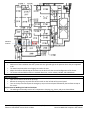
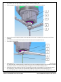
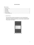
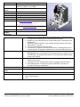
Name
Description
Manufacturer and
Model
Location
SOP Creation Date
SOP Created By
SOP Revision Date
SOP Revised By
SOP Location
Manual Location
Equipment Owner
Support
Technicians
Refill friction stir spot welder
RPS 100 spot friction welding system
Valid from software version V02.21
Harms & Wende GmbH & Co KG
E3 2118J
2014-09-11
Yuyang Chen
•
•
•
•
inv.mme.uwaterloo.ca
other physical or online locations
no need for specific link
usually inv.mme.uwaterloo.ca or an office
location if electronic copy is not available
Adrian Gerlich
Significant Hazards
1. A pinch hazard is at the welding tool, this can apply up to 11 kN of force on the
C-clamp when the welding cycle is activated by the foot switch.
2. Workpieces can be rotated due to the friction welding tools or ejected out of the
welding zone;
3. Continuous rotation cannot be safely detected after tool breakage, injury from
tool fragments is possible;
4. Incorrect commissioning or defective wiring.
5. The machine is designed so that it must be placed in a working position from a
transport position. An ergonomic position can be set via the hand ratchet lever
Administrative Controls
All users must be authorized by the equipment owner (Prof. Adrian Gerlich)
Work practices such as standards and operating procedures (including training,
housekeeping, and equipment maintenance, etc) must be done before having
access to the machine.
1. Keep the water cooling on when the machine is running to reduce the heat
influence on the tools;
2. Cleaning the tools on a regular basis to prevent clogging materials and rust;
3. Enclosed equipment, for example, is tightly sealed and it is typically only
opened for cleaning or maintenance.
Gloves, safety glasses, and appropriate clothing are mandatory.
the Machinery Directive (2006/42/EC)
Engineering Controls
PPE Required
Relevant Standards and
Codes
Relevant MSDS
Accident Procedure
•
•
Sodium hydroxide (NaOH)
inform equipment owner(Prof. Adrian Gerlich) and support technicians (James
Merli, Richard Gordon)
UVV
last editted by: Yuyang Chen
last edited: 3/12/2015 2:52:00 PM
Page 1 of 1
filename: SOP-RFSSW -revised 15-03-12.docx
based on MME SOP Template v.2014-06-03
Emergency Shutdown
Procedure
1. When the foot switch is pressed in the middle position, the welding cycle
engages. In the case of emergency, either release or fully press the foot switch to
reverse the gun to its original position. If necessary, remove the workpiece held in a
wrap-around grip from the joint zone and put down safely. When the gun is open,
press the emergency stop to deactivate the spindle rotation.
2. When the foot switch is not pressed upon the occurrence of danger, press the
emergency stop button immediately and safely deposit the workpieces in a wraparound grib. (The gun opens upon ‘Emergency stop’.)
• After an emergency, malfunction or irregularities, the instruction is as follows:
1. Secure the system to prevent unintentional switch-on and uncontrolled
movement.
2. Seal off the danger zone to prevent inadvertent and uncontrolled access.
3. To avoid direct or indirect consequences to people or property, immediately
inform the relevant specialist personnel.
4. In case of fire observe the material safety data sheets for the hydraulic fluids and
materials used as well as your location-specific fire safety measures.
•
last editted by: Yuyang Chen
last edited: 3/12/2015 2:52:00 PM
Page 2 of 2
filename: SOP-RFSSW -revised 15-03-12.docx
based on MME SOP Template v.2014-06-03
Clamping piston
C-frame vertical position
ratchet lever adjustment
Control Cabinet
Weld head
Welding
tool
Clamping piston
pressure regulator
Touch panel (w/control
unit)
Transport unit
Emergency Stop
Foot switch
last editted by: Yuyang Chen
last edited: 3/12/2015 2:52:00 PM
Page 3 of 3
filename: SOP-RFSSW -revised 15-03-12.docx
based on MME SOP Template v.2014-06-03
Machine
location
Pre-start Checklist
• The machine is in the correct working position with the four rollers secured.
• Make sure of the installation that the 3-piece tools are right and tight in the position where they are supposed
to be.
• The waterline plastic tubes are all tightly secured in the nuts.
• Adjust the location of backstops of the fixture or the brick to fit the size and configuration of the sheets.
• The sheets to be welded should be in standard dimension, such as 100x25, 140x60, and 150x100mm.
Start-up Procedure
• Open the air valve to let in the air pressure.
• Release the emergency stop and twist off the switch on the left side of the control panel.
• Turn on the key switch and open the emergency stop on the touch panel followed by the interface startup on
the screen.
Replacement of Welding Tool and Tool Positions
• The welding tool assembly consists of 3 components: clamping ring, sleeve, and pin as shown below.
last editted by: Yuyang Chen
last edited: 3/12/2015 2:52:00 PM
Page 4 of 4
filename: SOP-RFSSW -revised 15-03-12.docx
based on MME SOP Template v.2014-06-03
Clamping Ring
Sleeve
Pin
Welding Tool Detail:
•
To remove the welding tool assembly from the machine, unscrew the 3 M5 fastening screws (See #1 below)
from the tool plunger (#2) and the 3 x M8 fastening screws (#4) from collar part 2 (#3) and detach the collar.
last editted by: Yuyang Chen
last edited: 3/12/2015 2:52:00 PM
Page 5 of 5
filename: SOP-RFSSW -revised 15-03-12.docx
based on MME SOP Template v.2014-06-03
•
•
•
•
•
•
•
Next, remove the tool sleeve by loosening the nut for the sleeve (#2 below) with a 32 mm open-ended wrench
(#1) and use a 23 mm open-ended wrench at (#3) to hold the coupling (#4).
Then unscrew the tool sleeve (#5 below) along with the coupling and nut for the sleeve.
Remove the tool pin using the special wrench (See #1 below, which is included in the tool kit) on the hollow
shaft (#3).
Use an 18 mm open-ended wrench (#2) to loosen and remove the nut (#4) for the pin.
Then pull out the pin (#5)
Mounting of the tool and reassembly is conducted in the reverse order as described above. Ensure that the nuts
are seated correctly, and thread onto the shaft freely (not cross threaded) and tighten to the end(the nut should
at least have three turns in the threads), apply some grease to the thread from now and then.
Setting the new home position of the tool is essential after the tool is reassembled. This corresponds to when
the clamping ring, sleeve, and pin are all positioned flat (flush) to the surface of the clamping ring. It is
necessary that the system can position the pin and sleeve to any arbitrary home position, and the machine can
last editted by: Yuyang Chen
last edited: 3/12/2015 2:52:00 PM
Page 6 of 6
filename: SOP-RFSSW -revised 15-03-12.docx
based on MME SOP Template v.2014-06-03
•
set this to an accuracy of 1/100 mm. The home position is stored as the fixed position in the system. It forms the
zero point of the PLC-internal machine coordinate system. Any home position can be set again in manual mode.
To access Manual mode, press on the touch controller as shown below while stepping on the footswitch, and
this will open the following menu:
•
In order to set the correct home position, the welding tool parts must be the level as shown:
•
The home position can be set to one level as above, by first retracting the sleeve and pin into the clamp. Then
lower the pin down as you use a straight edge to detect when the pin reaches the level of the clamp. You can
detect this by observing when the straight edge does not rock back and forth over the pin as you lower (in 0.05
mm increments), or by using a depth gauge. Ensure the key switch is off when position tools near the clamp.
Then move the sleeve down until it is flat with the pin. It may be useful to slide the corner edge of piece of
•
last editted by: Yuyang Chen
last edited: 3/12/2015 2:52:00 PM
Page 7 of 7
filename: SOP-RFSSW -revised 15-03-12.docx
based on MME SOP Template v.2014-06-03
aluminum sheet metal to feel when the sleeve and pin interfaces are no longer detected as boundaries/edges.
Operating Procedure
(a)
(b)
(c)
(d)
Welding Process overview: a) clamping and spindles rotation, b) sleeve plunges into the sheets while pin
moves upwards, c) sleeve retracts back, and d) withdrawal of welding head
•
Turn on the water cooling system.
•
Press the recipe button
the folder button
•
, select the welding parameter needed, and send it to the actuator by pressing
.
Go to the automatic mode
and start the initial warm-up by pressing the foot switch
(If the original position of the pin and sleeve is not aligned, go to the manual mode
position of the tooling.)
•
•
•
•
.
to change the home
Go through the cleaning cycle
by pressing the foot switch up to the pressing point until there is no
clogging material hurled out of the tooling.
If the machine is not in idle before starting the first, allow at least 1 minute of idling before starting a weld.
Start welding by activating the foot switch (to the middle position). Ensure the foot switch is held until the tool
is retracted from the weld. If the foot switch is released, or pressed to the fully down ‘1’ position, the
emergency stop will engage, and the tooling must be reset.
If any parameters need to be changed for the next weld, the settings must be reloaded to the controller as per
the sequence above.
Shutdown Procedure
• After completing the welding process, go through cleaning cycle a couple of times to get rid of the material
residue in the tooling. (If the material accumulated is brittle and easy to get hardened(such as Al 5000 series),
potential harsh sound is heard when tool is idling. Then chances are that automated cleaning cycle is operated
so fast that the torque between hardened accumulated material and tool might break the tool. Thereby, maunal
mode cleaning is always PREFERED before you make sure that you can go on to the next step, that is, the
automated cleaning cycle. In fact, manual mode cleaning with different rotation speeds, spindle and link-up
sleeve set-up, and sleeve or pin travel distances can easily replace automated cleaning cycle as long as with
enough effort and time put into it. To be noted, always start with the lower rotational speed in manual cleaning
and then gradually change the travel distances of sleeve and pin, and then rotate the sleeve and pin again. Then
last editted by: Yuyang Chen
last edited: 3/12/2015 2:52:00 PM
Page 8 of 8
filename: SOP-RFSSW -revised 15-03-12.docx
based on MME SOP Template v.2014-06-03
if there is still harshsound caused by accumulated material, we could press link-up spindle
to get the
sleeve or pin spinning while it’s going up and down, that is, simultaneous spinning with sleeve or pin travel. This
way is more drastic and efficient cleaning than the former way mentioned. For simultaneus travelling of sleeve
and pin, link-up sleeve
•
•
•
•
can be pressed. Last but not least, travel speed of sleeve and pin can be changed
by pressing
. In all circumstances in cleaning, LOWER travel speed such as 0.1mm/s is recommended in
cleaning cycle. ALWAYS remember to put the travel speed BACK to 1mm/s after cleaning cycle. In short, always
pay attention to potential noise which might indicate that there is brittle material in this area that needs to be
cleaned.)
Release the foot switch completely by pushing the blue button.
Shut down the touch panel by turning off the key switch and opening the emergency stop.
Shut down the control cabinet by twisting off the switch and opening the emergency stop.
Close the air valve.
Clean-up
• The tool set must be removed and cleaned after welding is completed for all tests on one material, or when
changing to different alloys.
• To remove aluminum residue, immerse the tools in 5% Sodium Hydroxide (NaOH) solution at approx. 70℃ for
20min. (Do not immerse the o-ring in the caustic solution.)(The tools can be sent to manufacturer for cleaning
and wear inspection as well as seal replacement as required.)
Lockout
• Preparation
Notify all affected workers that a lockout is required and the reason for the lockout.
• Machine or Equipment Shutdown and Isolation
1. If the equipment is operating, shut it down by the normal stopping procedure (depress stop button, open
toggle switch, etc.). Only workers knowledgeable in the operation of the specific equipment should perform
shutdown or re-start procedures.
2. Operate the energy-isolating device(s) so that all energy sources (electrical, mechanical, hydraulic,etc.) are
disconnected or isolated from the equipment.
3. Electrical disconnect switches should never be pulled while under load, because of the possibility of arcing
or even explosion.
4. Stored energy, such as that in capacitors, springs, elevated machine parts, rotating flywheels, hydraulic
systems, and air, gas, steam, or water pressure, etc., must also be released, disconnected, or restrained by
methods such as grounding, repositioning, blocking or bleeding-down.
5. Pulling fuses is not a substitute for locking out. A pulled fuse is no guarantee the circuit is dead. Even if a
circuit is dead, another person could inadvertently replace the fuse.
6. Equipment that operates intermittently, such as a pump, blower, fan or compressor may seem harmless
when it is not running. Do not assume that because equipment is not operating at a particular point in time
that it will remain off for the duration of any work to be performed on it.
Maintenance and Repair
Please refer to the RPS100 user manual and RPS100 operation instructions for more information.
last editted by: Yuyang Chen
last edited: 3/12/2015 2:52:00 PM
Page 9 of 9
filename: SOP-RFSSW -revised 15-03-12.docx
based on MME SOP Template v.2014-06-03
SOP Accepted by Equipment Owner
X
owner
name
Signature
date (yyyy-mm-dd)
Authorized Trainers
X
X
trainer
owner
X
X
trainer
owner
X
X
trainer
owner
trainer
authorized by
name
name
Date
last editted by: Yuyang Chen
last edited: 3/12/2015 2:52:00 PM
Page 10 of 10
filename: SOP-RFSSW -revised 15-03-12.docx
based on MME SOP Template v.2014-06-03
signature
signature
name
name
signature
signature
name
name
signature
signature
Authorized Operators
X
X
operator
trainer
X
X
operator
trainer
X
X
operator
trainer
X
X
operator
trainer
last editted by: Yuyang Chen
last edited: 3/12/2015 2:52:00 PM
Page 11 of 11
filename: SOP-RFSSW -revised 15-03-12.docx
based on MME SOP Template v.2014-06-03
operator
trainer
name
name
signature
signature
name
name
signature
signature
name
name
signature
signature
date
last editted by: Yuyang Chen
last edited: 3/12/2015 2:52:00 PM
Page 12 of 12
filename: SOP-RFSSW -revised 15-03-12.docx
based on MME SOP Template v.2014-06-03