1
User's Manual
32
RZ/A1H Group
Renesas Starter Kit+ Tutorial Manual
For DS-5
RENESAS MCU
RZ Family / A1H Series
All information contained in these materials, including products and product specifications, represents
information on the product at the time of publication and is subject to change by Renesas Electronics
Corporation without notice. Please review the latest information published by Renesas Electronics
Corporation through various means, including the Renesas Electronics Corporation website
(http://www.renesas.com).
www.renesas.com
Rev. 2.00 Mar 2014
Notice
1.
Descriptions of circuits, software and other related information in this document are provided only to illustrate the
operation of semiconductor products and application examples. You are fully responsible for the incorporation of these
circuits, software, and information in the design of your equipment. Renesas Electronics assumes no responsibility for
any losses incurred by you or third parties arising from the use of these circuits, software, or information.
2. Renesas Electronics has used reasonable care in preparing the information included in this document, but Renesas
Electronics does not warrant that such information is error free. Renesas Electronics assumes no liability whatsoever
for any damages incurred by you resulting from errors in or omissions from the information included herein.
3. Renesas Electronics does not assume any liability for infringement of patents, copyrights, or other intellectual property
rights of third parties by or arising from the use of Renesas Electronics products or technical information described in
this document. No license, express, implied or otherwise, is granted hereby under any patents, copyrights or other
intellectual property rights of Renesas Electronics or others.
4. You should not alter, modify, copy, or otherwise misappropriate any Renesas Electronics product, whether in whole or
in part. Renesas Electronics assumes no responsibility for any losses incurred by you or third parties arising from such
alteration, modification, copy or otherwise misappropriation of Renesas Electronics product.
5. Renesas Electronics products are classified according to the following two quality grades: “Standard” and “High
Quality”. The recommended applications for each Renesas Electronics product depends on the product’s quality grade,
as indicated below.
“Standard”: Computers; office equipment; communications equipment; test and measurement equipment; audio
and visual equipment; home electronic appliances; machine tools; personal electronic equipment; and industrial
robots etc.
“High Quality”: Transportation equipment (automobiles, trains, ships, etc.); traffic control systems; anti-disaster
systems; anticrime systems; and safety equipment etc.
Renesas Electronics products are neither intended nor authorized for use in products or systems that may pose a
direct threat to human life or bodily injury (artificial life support devices or systems, surgical implantations etc.), or may
cause serious property damages (nuclear reactor control systems, military equipment etc.). You must check the quality
grade of each Renesas Electronics product before using it in a particular application. You may not use any Renesas
Electronics product for any application for which it is not intended. Renesas Electronics shall not be in any way liable
for any damages or losses incurred by you or third parties arising from the use of any Renesas Electronics product for
which the product is not intended by Renesas Electronics.
6. You should use the Renesas Electronics products described in this document within the range specified by Renesas
Electronics, especially with respect to the maximum rating, operating supply voltage range, movement power voltage
range, heat radiation characteristics, installation and other product characteristics. Renesas Electronics shall have no
liability for malfunctions or damages arising out of the use of Renesas Electronics products beyond such specified
ranges.
7. Although Renesas Electronics endeavors to improve the quality and reliability of its products, semiconductor products
have specific characteristics such as the occurrence of failure at a certain rate and malfunctions under certain use
conditions. Further, Renesas Electronics products are not subject to radiation resistance design. Please be sure to
implement safety measures to guard them against the possibility of physical injury, and injury or damage caused by fire
in the event of the failure of a Renesas Electronics product, such as safety design for hardware and software including
but not limited to redundancy, fire control and malfunction prevention, appropriate treatment for aging degradation or
any other appropriate measures. Because the evaluation of microcomputer software alone is very difficult, please
evaluate the safety of the final products or systems manufactured by you.
8. Please contact a Renesas Electronics sales office for details as to environmental matters such as the environmental
compatibility of each Renesas Electronics product. Please use Renesas Electronics products in compliance with all
applicable laws and regulations that regulate the inclusion or use of controlled substances, including without limitation,
the EU RoHS Directive. Renesas Electronics assumes no liability for damages or losses occurring as a result of your
noncompliance with applicable laws and regulations.
9. Renesas Electronics products and technology may not be used for or incorporated into any products or systems whose
manufacture, use, or sale is prohibited under any applicable domestic or foreign laws or regulations. You should not
use Renesas Electronics products or technology described in this document for any purpose relating to military
applications or use by the military, including but not limited to the development of weapons of mass destruction. When
exporting the Renesas Electronics products or technology described in this document, you should comply with the
applicable export control laws and regulations and follow the procedures required by such laws and regulations.
10. It is the responsibility of the buyer or distributor of Renesas Electronics products, who distributes, disposes of, or
otherwise places the product with a third party, to notify such third party in advance of the contents and conditions set
forth in this document, Renesas Electronics assumes no responsibility for any losses incurred by you or third parties as
a result of unauthorized use of Renesas Electronics products.
11. This document may not be reproduced or duplicated in any form, in whole or in part, without prior written consent of
Renesas Electronics.
12. Please contact a Renesas Electronics sales office if you have any questions regarding the information contained in this
document or Renesas Electronics products, or if you have any other inquiries.
(Note 1) “Renesas Electronics” as used in this document means Renesas Electronics Corporation and also includes its
majority owned subsidiaries.
(Note 2) “Renesas Electronics product(s)” means any product developed or manufactured by or for Renesas Electronics.
(2012.4)
Disclaimer
By using this Renesas Starter Kit (RSK), the user accepts the following terms:
The RSK is not guaranteed to be error free, and the entire risk as to the results and performance of the RSK is
assumed by the User. The RSK is provided by Renesas on an “as is” basis without warranty of any kind whether
express or implied, including but not limited to the implied warranties of satisfactory quality, fitness for a particular
purpose, title and non-infringement of intellectual property rights with regard to the RSK. Renesas expressly
disclaims all such warranties. Renesas or its affiliates shall in no event be liable for any loss of profit, loss of data,
loss of contract, loss of business, damage to reputation or goodwill, any economic loss, any reprogramming or recall
costs (whether the foregoing losses are direct or indirect) nor shall Renesas or its affiliates be liable for any other
direct or indirect special, incidental or consequential damages arising out of or in relation to the use of this RSK, even
if Renesas or its affiliates have been advised of the possibility of such damages.
Precautions
The following precautions should be observed when operating any RSK product:
This Renesas Starter Kit is only intended for use in a laboratory environment under ambient temperature and humidity
conditions. A safe separation distance should be used between this and any sensitive equipment. Its use outside the
laboratory, classroom, study area or similar such area invalidates conformity with the protection requirements of the
Electromagnetic Compatibility Directive and could lead to prosecution.
The product generates, uses, and can radiate radio frequency energy and may cause harmful interference to radio
communications. However, there is no guarantee that interference will not occur in a particular installation. If this
equipment causes harmful interference to radio or television reception, which can be determined by turning the
equipment off or on, you are encouraged to try to correct the interference by one or more of the following measures;
ensure attached cables do not lie across the equipment
reorient the receiving antenna
increase the distance between the equipment and the receiver
connect the equipment into an outlet on a circuit different from that which the receiver is connected
power down the equipment when not in use
consult the dealer or an experienced radio/TV technician for help NOTE: It is recommended that wherever
possible shielded interface cables are used.
The product is potentially susceptible to certain EMC phenomena. To mitigate against them it is recommended that the
following measures be undertaken;
The user is advised that mobile phones should not be used within 10m of the product when in use.
The user is advised to take ESD precautions when handling the equipment.
The Renesas Starter Kit does not represent an ideal reference design for an end product and does not fulfil the
regulatory standards for an end product.
How to Use This Manual
1.
Purpose and Target Readers
This manual is designed to provide the user with an understanding of how to use the DS-5 IDE to develop and
debug software for the RSK platform. It is intended for users designing sample code on the RSK platform,
using the many different incorporated peripheral devices.
The manual comprises of step-by-step instructions to load and debug a project in DS-5, but does not intend to
be a complete guide to software development on the RSK platform. Further details regarding operating the
RZA1H microcontroller may be found in the Hardware Manual and within the provided sample code.
Particular attention should be paid to the precautionary notes when using the manual. These notes occur within the body
of the text, at the end of each section, and in the Usage Notes section.
The revision history summarizes the locations of revisions and additions. It does not list all revisions. Refer to the text of
the manual for details.
The following documents apply to the RZA1H Group. Make sure to refer to the latest versions of these
documents. The newest versions of the documents listed may be obtained from the Renesas Electronics Web
site.
Document Type
Description
Document Title
Document No.
User’s Manual
Describes the technical details of the RSK hardware.
RSK+RZA1H User’s
Manual
R20UT2587EG
Tutorial
Provides a guide to setting up RSK environment,
running sample code and debugging programs.
RSK+RZA1H
Tutorial Manual
R20UT2845EG
Quick Start Guide
Provides simple instructions to setup the RSK and
run the first sample, on a single A4 sheet.
RSK+RZA1H Quick
Start Guide
R20UT2588EG
Schematics
Full detail circuit schematics of the RSK.
RSK+RZA1H
Schematics
R20UT2586EG
Hardware Manual
Provides technical
microcontroller.
RZA1H
Group
Hardware Manual
R01UH0403EJ
details
of
the
RZA1H
2.
List of Abbreviations and Acronyms
Abbreviation
ADC
DS-5
EMC
ESD
J-LINK
LCD
LED
MCU
QSPI
RSK
RSK+
Full Form
Analog-to-Digital Converter
ARM Development Studio Integrated Debugging Environment
Electromagnetic Compatibility
Electrostatic Discharge
On-chip Debugger
Liquid Crystal Display
Light Emitting Diode
Micro-controller Unit
Quad Serial Programming Interface
Renesas Starter Kit
Renesas Starter Kit + (denotes extra functionality over standard RSK)
Table of Contents
1. Overview............................................................................................................................7 1.1 1.2 Purpose......................................................................................................................................................7 Features .....................................................................................................................................................7 2. Introduction........................................................................................................................8 2.1 Note Regarding Source Code....................................................................................................................8 3. Tutorial Project Workspace ................................................................................................9 3.1 3.2 3.3 3.4 3.5 3.6 3.7 Introduction ................................................................................................................................................9 Jumper and Switch Configuration..............................................................................................................9 Starting DS-5 and Importing Sample Code................................................................................................9 Adding GNU Toolchain Support for DS-5 ................................................................................................12 Build Configurations and Debug Sessions ..............................................................................................16 Running the Tutorial.................................................................................................................................20 Running the code from the QSPI Flash ROM..........................................................................................21 4. Reviewing the Tutorial Program.......................................................................................23 4.1 Main Functions.........................................................................................................................................23 5. QSPI Boot Loader............................................................................................................27 5.1 5.2 5.3 5.4 Loading Process ......................................................................................................................................27 Boot Loader Sections...............................................................................................................................28 Generating a Binary File ..........................................................................................................................29 Programming a User Application Program ..............................................................................................29 6. Additional Information ......................................................................................................30 RSK+RZA1H
RENESAS STARTER KIT
R20UT2845EG0200
Rev. 2.00
Mar 21, 2014
1. Overview
1.1
Purpose
This RSK is an evaluation tool for Renesas microcontrollers. This manual describes how to get the RSK
tutorial started, and basic debugging operations.
1.2
Features
This RSK provides an evaluation of the following features:
Renesas microcontroller programming
User code debugging
User circuitry such as switches, LEDs and a potentiometer
Sample application
Sample peripheral device initialisation code
The RSK board contains all the circuitry required for microcontroller operation.
R20UT2845EG0200 Rev. 2.00
Mar 21, 2014
Page 7 of 34
RSK+RZA1H
2. Introduction
2. Introduction
This manual is designed to answer, in tutorial form, the most common questions asked about using a Renesas
Starter Kit (RSK). The tutorials help explain the following:
How do I compile, link, download and run a simple program on the RSK?
How do I build an embedded application?
How do I use Renesas’ tools?
Files referred to in this manual are installed using the import wizard as you work through the tutorials. The
tutorial examples in this manual assume that installation procedures described in the RSK+ Quick Start Guide
have been completed. Please refer to the Quick Start Guide for details of preparing the configuration.
These tutorials are designed to show you how to use the RSK and are not intended as a comprehensive introduction to
the DS-5 environment, compiler toolchains or the J-Link Lite debugger. Please refer to the relevant user manuals for
more in-depth information.
2.1
Note Regarding Source Code
Due to the project generator, it is possible that line numbers for source code illustrated in this document do not
match exactly with that in the actual source files. It is also possible that the source address of instructions
illustrated in this manual differ from those in user code compiled from the same source. These differences are
minor, and do not affect the functionality of the sample code nor the validity of this manual.
R20UT2845EG0200 Rev. 2.00
Mar 21, 2014
Page 8 of 34
RSK+RZA1H
3. Tutorial Project Workspace
3. Tutorial Project Workspace
3.1
Introduction
DS-5 is an integrated development tool that allows the user to write, compile, program and debug a software
project on the RZ family of Renesas microcontrollers. DS-5 will have been installed during the installation of
the software support for the Renesas Starter Kit product. This manual will describe the stages required to
create and debug the supplied tutorial code.
3.2
Jumper and Switch Configuration
Ensure jumpers and switches are in the following positions:
Jumper
JP11
JP12
JP18
JP21
PWR_SEL
----
3.3
Pins
2-3
1-2
1-2
1-2
2-3
----
Switch
SW4-1
SW4-2
SW4-3
SW4-4
SW4-5
SW4-6
SW4-7
SW4-8
Position
OFF
OFF
OFF
OFF
OFF
OFF
OFF
OFF
Switch
SW6-1
SW6-2
SW6-3
SW6-4
SW6-5
SW6-6
---
Position
OFF
ON
OFF
ON
ON
ON
---
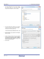
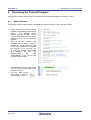
Starting DS-5 and Importing Sample Code
Start Eclipse for DS-5 by selecting it from the
Start Menu -> All Programs -> ARM DS-5 ->
Eclipse for DS-5. The first dialog box to
appear will be the Workspace Launcher.
Click ‘Browse’ and select a suitable location to
store your workspace, using the ‘Create New
Folder’ option as necessary. Click ‘OK’.
Note: The Workspace location does not have to contain your project files, the workspace contains the
configuration of the tool and can group projects together. Projects may be referred to from this location, or the
projects may be stored under this directory.
R20UT2845EG0200 Rev. 2.00
Mar 21, 2014
Page 9 of 34
RSK+RZA1H
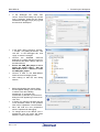
The DS-5 welcome splash screen will appear.
Click the ‘Go to the workbench’ arrow button
on the far right (circled in the screenshot
opposite).
Once the environment has initialised, right
click in the ‘Project Explorer’ window and
select ‘Import…’
R20UT2845EG0200 Rev. 2.00
Mar 21, 2014
3. Tutorial Project Workspace
Page 10 of 34
RSK+RZA1H
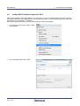
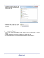
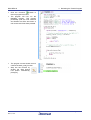
The Import dialog box will now show. Expand
the ‘General’ folder icon, and select ‘Existing
Projects into Workspace’, then click ‘Next’.
The Import dialog box will allow you to specify
a project to import. Click the ‘Browse’ button
and locate the following directory:
3. Tutorial Project Workspace
C:\Renesas\Workspace\RSK\RSK+RZA1_V02
Ensure that the ‘Copy projects into workspace’
option is ticked.
Caution: Ticking this box will copy the projects
from the location where they were installed. It
is important to select this option to preserve
the projects that were installed so that you can
return to them in the future.
Click ‘Finish’.
R20UT2845EG0200 Rev. 2.00
Mar 21, 2014
Page 11 of 34
RSK+RZA1H
3.4
3. Tutorial Project Workspace
Adding GNU Toolchain Support for DS-5
After initial installation of the RSK+RZA1H, it is necessary to import the GNU ARM-RZ Toolchain into DS-5.
The steps required to import the toolchain are described in this section. Note that these steps only need to be
performed once per WindowsTM workstation.
This process will require internet access to download the referenced packages.
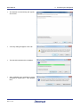
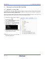
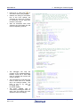
From the DS-5 ‘Help’ menu, select ‘Install
New Software…’
From the Install dialog, select ‘Add…’.
R20UT2845EG0200 Rev. 2.00
Mar 21, 2014
Page 12 of 34
RSK+RZA1H
3. Tutorial Project Workspace
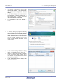
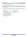
The Add Repository dialog box will allow
you to specify the .zip archive which is
supplied with the RSK.
Click the
‘Archive..’ button and browse to
C:\Renesas\Workspace\RSK\RSK+RZA1_V0
2\Renesas_ARM-RZ_Update.zip
Click ‘OK’ .
Back in the ‘Install’ dialog, ensure that the
tick box next to ‘Renesas ARM-RZ
Update’ is selected, then click ‘Next >’.
The Install dialog will appear, click ‘Next’.
R20UT2845EG0200 Rev. 2.00
Mar 21, 2014
Page 13 of 34
RSK+RZA1H
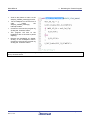
The Review Licenses dialog will appear,
click ‘Finish’.
A security dialog will appear. Click ‘OK’.
The toolchain software will be installed.
After installation has completed it will be
necessary to restart DS-5. Click ‘Restart
Now’.
R20UT2845EG0200 Rev. 2.00
Mar 21, 2014
3. Tutorial Project Workspace
Page 14 of 34
RSK+RZA1H
Once DS-5 has restarted, in the DS-5
‘Help’ menu, there will now be a new item
‘Integrate Toolchain’. Select this menu
item.
In the ‘Preferences’ dialog, under ‘C/C++
-> Renesas -> Renesas Toolchain
Management’, ensure the tick-box is
checked as shown opposite, then click
‘OK’.
R20UT2845EG0200 Rev. 2.00
Mar 21, 2014
3. Tutorial Project Workspace
Page 15 of 34
RSK+RZA1H
3.5
Build Configurations and Debug Sessions
3.5.1
Build Configuration
3. Tutorial Project Workspace
The DS-5 workspace will be created with two build configurations: ‘Debug’ and ‘Release’.
Debug
This default build mode has all optimisation turned off, and provides full debug information. This is the best
configuration to use whilst developing code as C code execution will be linear. The ‘Debug’ build configuration
provided for this Tutorial program is configured to load the code directly into RAM.
Click the top level ‘Tutorial’ folder again,
and then the arrow next to the build
button (hammer icon),
and select the ‘Debug’
option.
DS-5 will now build the code.
The output from the build process will be
presented in the console window of DS5
3.5.2
Debug Configuration
Click the arrow next to the debug button
(bug icon). Select ‘Debug
Configurations’.
The ‘Debug Configurations’ dialog box
will appear. Click on the ‘DS-5 Debugger’
icon.
to create a
Press the ‘New’ button
new DS-5 Debugger configuration.
R20UT2845EG0200 Rev. 2.00
Mar 21, 2014
Page 16 of 34
RSK+RZA1H
The debug configurations control page
will then be created. In the ‘Connection’
tab, rename the configuration ‘Tutorial
Debug’.
In the ‘Select Target’ tree control, ensure
that ‘Renesas -> RZ/A1H R7S721001 ->
Bare Metal Debug -> Debug Cortex-A9
via DSTREAM/RVI’ is selected.
In ‘Connections’, click the ‘Browse…’
button.
A security dialog may appear indicating
that the Windows Firewall has blocked
some features of the eclipse platform.
Under ‘Allow eclipse to communicate on
these networks’, ensure the check box
next to ‘Private networks, such as my
home or work network’ is ticked. Click
‘Allow access’
In the ‘Select Debug Hardware’ dialog,
select ‘J-LinkUSB:xxxxxxxx’. Click OK.
Append “:device R7S721001_DualSPI”
to the connection serial number string,
for example “J-LinkUSB:xxxxxxxx:device
R7S721001_DualSPI”.
In the ‘Connection’ tab click ‘Apply’, then
select the ‘Files’ tab.
R20UT2845EG0200 Rev. 2.00
Mar 21, 2014
3. Tutorial Project Workspace
Page 17 of 34
RSK+RZA1H
In the ‘Files’ tab, under ‘Target
Configuration -> Application on host to
download’, click the ‘Workspace’ button.
Browse to ‘Tutorial -> Debug ->
RZ_A1H_Tutorial_RSK.x’ and click OK.
Click ‘Apply’ to save the changes, then
select the ‘Debugger’ tab.
R20UT2845EG0200 Rev. 2.00
Mar 21, 2014
3. Tutorial Project Workspace
Page 18 of 34
RSK+RZA1H
In the ‘Debugger’ tab, under ‘Run
control’, ensure that ‘Debug from symbol
main’ is selected. Select the ‘Run target
initialization debugger script (.ds/ py)’ tick
box and click ‘Workspace’.
In the ‘Open’ dialog, browse to ‘Tutorial > Scripts ->init_RAM_RZ-A1H.ds’ and
click OK. In the ‘Debugger’ tab, click
‘Apply’ to save the changes.
Connect
the
SEGGER
JLink-Lite
debugger to a spare USB port on the PC
and connect the ribbon cable to CN14 on
the RSK+RZA1H.
Ensure the PWR_SEL jumper is set to
match the power supply. See the
RSK+RZA1H User’s manual to locate
the PWR_SEL jumper.
Connect a PSU to the RSK+RZA1H
PWR connector and apply power.
Click ‘Debug’ to start the new debug
session.
Before downloading the code a dialog
box will appear asking if you would like
to switch to the ‘DS-5 Debug
perspective’. If you agree click
‘Remember my decision’ to prevent this
dialog box from appearing in future, then
click ‘Yes’.
A dilaog may appear indicating that the
J-Link firmware needs to be updated.
Click ‘Yes’ to update the J-Link firmware.
DS-5 will load the new perspective,
which is optimised for debugging.
To change back to the default ‘C/C++’
perspective, from the menu bar select
Window > Open Perspective > Other
R20UT2845EG0200 Rev. 2.00
Mar 21, 2014
3. Tutorial Project Workspace
Page 19 of 34
RSK+RZA1H
The ‘Open Perpsective’ dialog box will
appear. Click on the desired perspective
to select it then ‘OK’.
Alternatively, click on the button within
the top right corner of the screen, as
shown opposite, and select the ‘C/C++’
perspective.
3.6
3. Tutorial Project Workspace
Running the Tutorial
Once the code has been downloaded the program counter will stop on the first instruction in the main
function.
Click the ‘Continue button in the ‘Debug’ perspective to run the rest of the code
It is recommended that you run the entire tutorial demo first, before continuing to debug it.
R20UT2845EG0200 Rev. 2.00
Mar 21, 2014
Page 20 of 34
RSK+RZA1H
3.7
Running the code from the QSPI Flash ROM
3.7.1
Debug Build – executing in RAM.
3. Tutorial Project Workspace
It is possible to run the above code from QSPI on start-up. For this to function, the boot loader should be
present in the QSPI. The board is shipped with pre-installed boot loader, but if this is changed in anyway, then
please re-install it using QSPI_LOADER sample.
On start-up, the boot loader will check the presence of the Tutorial code and then execute it. If the code is not
present, it will flash the LED1 continuously. The code can be loaded as follows:
Disconnect the debug session using the
disconnect icon.
Open the Windows Explorer and select
the Tutorial project directory.
Execute the file LoadTutorialToQSPI.bat.
Select Option 1 – Debug. This will now
load the Tutorial code into QSPI.
Restart the board by disconnecting and
reconnecting the power supply and the
Tutorial code will run by iteself.
Note:
Please refer to section 5.3 for information
on generating binary files.
R20UT2845EG0200 Rev. 2.00
Mar 21, 2014
Page 21 of 34
RSK+RZA1H
3.7.2
3. Tutorial Project Workspace
Release Build – executing from QSPI
The release build code will run directly from QSPI instead of transferring into RAM. It is possible to run the
above code from QSPI on start-up. For this to function, the boot loader should be present in the QSPI. The
board is shipped with pre-installed boot loader, but if this is changed in anyway, then please re-install it using
QSPI_LOADER sample.
On start-up, the boot loader will check the presence of the above code, and then transfer it into RAM and
execute it. If the code is not present, it will flash the LED1 continuously. The code can be loaded as follows:
Start the Tutorial project in DS5 as
described above.
Select the arrow next to hammer icon,
and select ‘Release’.
Open the Windows Expolrer and select
the Tutorial project directory.
Execute the file LoadTutorialToQSPI.bat.
Select Option 2 – Release. This will now
load the Tutorial code into QSPI.
Restart the board and the Tutorial code
will run by iteself.
R20UT2845EG0200 Rev. 2.00
Mar 21, 2014
Page 22 of 34
RSK+RZA1H
4. Reviewing the Tutorial Program
4. Reviewing the Tutorial Program
This section will look at each section of the tutorial code and basic debugging functionality in DS-5.
4.1
Main Functions
This section will look at the program code called from with the main() function, and how it works.
Start a debug session for the Tutorial
program as described in the previous
section.
The debugger should
connect and the program will be
stopped on the first line of the main()
function as shown in the screenshot
opposite.
Click on the line containing the
‘flashled()’ function call in ‘main()’ to
position the cursor. Right-click and
select ‘Run to Selection’ to execute
the program up to this line. The
‘R_LCD_Init()’ function call enables
and configures the LCD, and
‘Display_LCD()’
will
write
“RSK+RZA1H” on the top line and
“Tutorial Sample” below.
Set a breakpoint on the ‘static_test()’
function call by double-clicking in the
breakpoint column.
Click the ‘Step Source
Line’ button to step into
the ‘flashled()’ function.
R20UT2845EG0200 Rev. 2.00
Mar 21, 2014
Page 23 of 34
RSK+RZA1H
Click the ‘Continue’
button to
resume program execution.
The program will now run the
flashled() function. This function
periodically polls the user switches
and flashes the LEDs 200 times or
until a user switch has been pressed.
The program counter should come to
a halt at the static_test() function.
Step into the function by
clicking the ‘Step Source
Line’ button. Alternatively,
press [F5].
R20UT2845EG0200 Rev. 2.00
Mar 21, 2014
4. Reviewing the Tutorial Program
Page 24 of 34
RSK+RZA1H
Press [F7] or ‘Step Out’
to
execute the static_test() function.
Observe the string on the bottom
line of the LCD change one
character at a time from ‘STATIC’
to TESTTEST’ as the ‘static_test’
function is executed.
After all characters have been
changed, the LCD bottom line will
return to displaying ‘STATIC’.
The debugger will stop the
program at the cleardisplayarea()
function. Press F6 or click ‘Step
Over’ to execute this function and
clear the display.
The next portion of code sets up a
timer to flash LEDs at a variable
rate in an interrupt handler. The
timer is set up by calls to
R_OSTM_Init()
and
R_OSTM_Open().
The timer variable rate is
controlled by reading the ADC in a
while loop and setting the timer
expiration value accordingly.
R20UT2845EG0200 Rev. 2.00
Mar 21, 2014
4. Reviewing the Tutorial Program
Page 25 of 34
RSK+RZA1H
Scroll to the bottom of main.c to the
Sample_OSTM0_Interrupt() function.
Set a breakpoint on the first line of
code
inside
the
Sample_OSTM0_Interrupt()
interrupt handler.
Continue to execute the program by
clicking the ‘Continue’ button.
The program will halt at the
breakpoint due to the timer’s period
elapsing.
Remove the breakpoint by doubleclicking on the breakpoint column.
Continue to execute the program by
clicking the ‘Continue’ button.
4. Reviewing the Tutorial Program
For further details regarding hardware configuration, please refer to the RSK+RZA1H User’s Manual and the RZA1H
Group Hardware Manual.
R20UT2845EG0200 Rev. 2.00
Mar 21, 2014
Page 26 of 34
RSK+RZA1H
5. QSPI Boot Loader
5. QSPI Boot Loader
5.1
Loading Process
When the configuration switch SW6 is set to OFF, ON, OFF, ON, ON, ON, the RZ/A1H processor configures
the QSPI bus controller in external address space read mode to boot and execute from location 0x1800000
(QSPI channel 0 bus area). It sets the QSPI in single device, one bit mode at the lowest speed. The boot
loader is only located in the first device (IC26) connected to QSPI channel 0’s Port 0. The following actions
takes place:
The boot loader will transfer a small section (section 1: Spibsc_init1) of the code into RAM and
execute it. This code will speed up the QSPI access before returning back to boot loader code, as the
speed cannot be altered whilst the code is running from QSPI.
The boot loader then transfers the next section (section 2: Spibsc_init2) of the code into RAM and
executes it. This code will change the QSPI mode of operation to dual QSPI in quad mode, enabling
data transfer of 8 bits at a time. It then checks if a user application is present in the QSPI starting from
location 0x18080000. The check is performed by reading a signature at offset 0x2C.
Offset 0x20 contains the start address of the code, offset 0x24 contains the end address, and 0x28
contains the execution start address.
It uses the above information to determine if the code has to be transferred into RAM (if the start
address is in RAM), or execute in QSPI.
It transfers the code if necessary and then jumps to the execution start address.
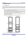
Transfer of QSPI device data to the RZ/A1H On-chip RAM
The QSPI Flash device is shown mapped to the RZ/A1H’s QSPI bus area.
R20UT2845EG0200 Rev. 2.00
Mar 21, 2014
Page 27 of 34
RSK+RZA1H
5.2
5. QSPI Boot Loader
Boot Loader Sections
The boot loader code is arranged in four sections, separate from the user application code (Tutorial). The
memory map from the previous page is explained below:
Section 1: 0x18000000 to 0x180002FF
This section contains the reset vectors and initialisation code.
Section 2: 0x18000300 to 0x180007FF
This section contains code to speed up the QSPI and set I/O ports (rza_io_regrw.c). This code is executed in
RAM as it cannot change the QSPI access speed when executing from it.
Section 3: 0x18000800 to 0x18005FFF
This section contains code to set QSPI into quad bit mode, using both the devices. This code is executed in
RAM as it cannot configure the QSPI when running executing from it. It then checks if there is an application
in the start location (0x18080000). If there is, it checks if this application should be executed from QSPI or
from RAM. For QSPI, it jumps to the start location; if not, it copies the code into RAM at location 0x20040000
and then jumps to it. Note: This section uses I/O functions from section 2, so they must not overlap.
Section 4: 0x18006000
This section contains the reset_handler and constant data. The reset vector in section 1 calls the
reset_handler.
Note:
The boot loader can be installed by first building the Release configuration of the RZ_A1H_QSPI_LOADER
sample project, and then executing the Program_QSPI_Loader.bat file located in the project directory. The
board is shipped with the boot loader pre-installed.
R20UT2845EG0200 Rev. 2.00
Mar 21, 2014
Page 28 of 34
RSK+RZA1H
5.3
5. QSPI Boot Loader
Generating a Binary File
Programming a user application requires the program file to be in binary format (.bin). By default the Debug
build is configured to generate ELF files with extensions .x and .mot while the Release build is configured to
generate an ELF file with extension .x and a binary file with extension .bin.
To generate a Debug build .bin file instead of a .mot file follow these steps:
1.
2.
3.
4.
5.
6.
In DS-5, click on the desired project under the ‘Project Explorer’ view.
From the menu bar select ‘File > Properties’.
In the Properties dialog select ‘C/C++ Build > Settings’
Change the ‘Configuration’ to debug, if it is not already selected.
Select the ‘Build Steps’ tab.
Change the ‘Post-build steps’ to:
arm-rz-eabi-objcopy -O binary ${ProjName}.x RZ_A1H_PTC_FIRST.bin&
7. Click ‘Apply’.
8. Click ‘OK’.
9. Rebuild the Debug configuration to generate the binary file.
5.4
Programming a User Application Program
Build the desired configuration of your application code or one of the provided sample code using the correct
QSPI load file (provided in the RZ_A1H_Tutorial_RSK sample code). Copy the following files from the
RZ_A1H_Tutorial_RSK folder to the root folder of your application:
LoadTutorialToQSPI.bat
LoadTutorialToQSPIDebug.Command
LoadTutorialToQSPIRelease.Command
Make the following changes, taking care not to add or remove spaces, to the line numbers in the
LoadTutorialToQSPI.bat file:
Line 4: Replace the word Tutorial with the name of your user application.
Line 32: Replace RZ_A1H_Tutorial_RSK with the name of your user application.
Line 52: Replace RZ_A1H_Tutorial_RSK with the name of your user application.
Line 73: Replace RZ_A1H_Tutorial_RSK with the name of your user application.
Lines 41-44 and 61-64 describes the operation of the Tutorial sample code, this can be changed to match the
user application’s operation.
Make the following changes, taking care not to add or remove spaces, to the line numbers in the
LoadTutorialToQSPIDebug.command and LoadTutorialToQSPIDebug.command files:
Line 10 and 11: Replace RZ_A1H_Tutorial_RSK with the name of your user application.
Run the LoadTutorialToQSPI.bat batch file.
The 'exec SetSkipProgOnCRCMatch=0' instruction in the command files checks if the boot loader program to
be loaded matches the existing boot loader code in the QSPI device. The 'loadbin' instruction will skip
programming if they match. A power cycle to the RSK+RZA1H may be required following a successful loading
of the user application.
R20UT2845EG0200 Rev. 2.00
Mar 21, 2014
Page 29 of 34
RSK+RZA1H
6. Additional Information
6. Additional Information
Technical Support
For details on how to use DS-5, refer to the
help file by opening DS-5, then selecting
Help > Help Contents from the menu bar.
For information about the RZA1H series microcontrollers refer to the RZA1H Group Hardware Manual.
Technical Contact Details
Please refer to the contact details listed in section 10 of the “Quick Start Guide”
General information on Renesas microcontrollers can be found on the Renesas website at:
http://www.renesas.com/
A real time operating system demonstration for the Renesas RZ microcontrollers (ARM Cortex-A9) is provided
free of charge by FreeRTOS. This can be found on the FreeRTOS website at:
http://www.freertos.org/Renesas_RZ_Cortex-A9-RTOS.html
Trademarks
All brand or product names used in this manual are trademarks or registered trademarks of their respective
companies or organisations.
Copyright
This document may be, wholly or partially, subject to change without notice. All rights reserved. Duplication of
this document, either in whole or part is prohibited without the written permission of Renesas Electronics
Europe Limited.
© 2014 Renesas Electronics Europe Limited. All rights reserved.
© 2014 Renesas Electronics Corporation. All rights reserved.
© 2014 Renesas Solutions Corp. All rights reserved.
R20UT2845EG0200 Rev. 2.00
Mar 21, 2014
Page 30 of 34
REVISION HISTORY
Rev.
RSK+RZA1H Tutorial Manual
Description
Date
Page
1.00
Nov 10, 2013
2.00
Mar 21, 2014
Summary
First Edition issued
Boot Loader section moved to the User Manual.
Renesas Starter Kit Manual: Tutorial Manual
Publication Date:
Rev. 2.00
Mar 21, 2014
Published by:
Renesas Electronics Corporation
http://www.renesas.com
SALES OFFICES
Refer to "http://www.renesas.com/" for the latest and detailed information.
California Eastern Laboratories, Inc.
4590 Patrick Henry Drive, Santa Clara, California 95054, U.S.A.
Tel: +1-408-919-2500, Fax: +1-408-988-0279
Renesas Electronics Europe Limited
Dukes Meadow, Millboard Road, Bourne End, Buckinghamshire, SL8 5FH, U.K
Tel: +44-1628-651-700, Fax: +44-1628-651-804
Renesas Electronics Europe GmbH
Arcadiastrasse 10, 40472 Düsseldorf, Germany
Tel: +49-211-65030, Fax: +49-211-6503-1327
Renesas Electronics (China) Co., Ltd.
7th Floor, Quantum Plaza, No.27 ZhiChunLu Haidian District, Beijing 100083, P.R.China
Tel: +86-10-8235-1155, Fax: +86-10-8235-7679
Renesas Electronics (Shanghai) Co., Ltd.
Unit 301, Tower A, Central Towers, 555 LanGao Rd., Putuo District, Shanghai, China
Tel: +86-21-2226-0888, Fax: +86-21-2226-0999
Renesas Electronics Hong Kong Limited
Unit 1601-1613, 16/F., Tower 2, Grand Century Place, 193 Prince Edward Road West, Mongkok, Kowloon, Hong Kong
Tel: +852-2886-9318, Fax: +852 2886-9022/9044
Renesas Electronics Taiwan Co., Ltd.
13F, No. 363, Fu Shing North Road, Taipei, Taiwan
Tel: +886-2-8175-9600, Fax: +886 2-8175-9670
Renesas Electronics Singapore Pte. Ltd.
80 Bendemeer Road, Unit #06-02 Hyflux Innovation Centre Singapore 339949
Tel: +65-6213-0200, Fax: +65-6213-0300
Renesas Electronics Malaysia Sdn.Bhd.
Unit 906, Block B, Menara Amcorp, Amcorp Trade Centre, No. 18, Jln Persiaran Barat, 46050 Petaling Jaya, Selangor Darul Ehsan, Malaysia
Tel: +60-3-7955-9390, Fax: +60-3-7955-9510
Renesas Electronics Korea Co., Ltd.
12F., 234 Teheran-ro, Gangnam-Gu, Seoul, 135-080, Korea
Tel: +82-2-558-3737, Fax: +82-2-558-5141
© 2014 Renesas Electronics Corporation. All rights reserved.
Colophon 2.0
RZA1H Group
R20UT2845EG0200