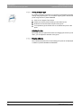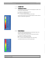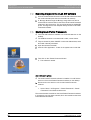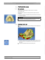
1
kÉï=~ë=çÑW== MNKOMNR áåi~Ä=m~êíá~ä=cê~ãÉïçêâ pçÑíï~êÉ=sÉêëáçå=NKMKM léÉê~íçêDë=j~åì~ä båÖäáëÜ Operator's Manual\rSoftware version 1.0.0 = Table of contents Sirona Dental Systems GmbH Operator's Manual inLab Partial Framework Table of contents 1 2 3 4 5 2 Introduction............................................................................................................... 5 1.1 Dear Customer, ............................................................................................. 5 1.2 Copyright and trademark............................................................................... 5 General data............................................................................................................. 6 2.1 General safety information ............................................................................ 6 2.2 Structure of the manual ................................................................................. 2.2.1 Identification of danger levels........................................................... 2.2.2 Formats and symbols used .............................................................. 2.2.3 Conventions ..................................................................................... 2.2.4 Formats of the manual ..................................................................... 2.2.5 File format ........................................................................................ 7 7 7 8 8 8 Getting started.......................................................................................................... 9 3.1 Installing the software ................................................................................... 9 3.2 Uninstalling the software ............................................................................... 9 3.3 Copy protection ............................................................................................. 10 3.4 Starting the software ..................................................................................... 10 User interface ........................................................................................................... 11 4.1 Phase bar ...................................................................................................... 4.1.1 PREPARATION ............................................................................... 4.1.2 DESIGN ........................................................................................... 4.1.3 COMPLETION ................................................................................. 12 12 12 12 4.2 Object bar...................................................................................................... 13 4.3 Tool wheel ..................................................................................................... 13 4.4 Step menu..................................................................................................... 13 4.5 System menu ................................................................................................ 4.5.1 Save case ........................................................................................ 4.5.2 Save the case under a different name ............................................. 4.5.3 License manager.............................................................................. 4.5.4 Window mode .................................................................................. 4.5.5 Current program version .................................................................. 4.5.6 Close the software ........................................................................... 14 14 15 15 15 15 15 Configuration ............................................................................................................ 16 5.1 16 16 16 Settings ......................................................................................................... 5.1.1 Reset notes ...................................................................................... 5.1.2 Selecting a language........................................................................ 65 38 222 D3534 D3534.208.01.01.02 01.2015 Sirona Dental Systems GmbH Table of contents 6 7 Construction elements............................................................................................. 17 6.1 Linear elements............................................................................................ 17 6.2 Laminar elements......................................................................................... 18 6.3 Additional elements ...................................................................................... 19 Editing orders .......................................................................................................... 20 7.1 Tools and functions of the page palette ....................................................... 7.1.1 Views............................................................................................... 7.1.2 Tools................................................................................................ 7.1.2.1 Form ................................................................................. 7.1.2.2 Editing lines ...................................................................... 7.1.2.3 Editing profile.................................................................... 7.1.2.4 Adding material................................................................. 7.1.2.5 Adding a grain .................................................................. 7.1.2.6 Adding a support pipe....................................................... 7.1.3 Display objects ................................................................................ 7.1.4 Analysis tools .................................................................................. 7.1.4.1 Displaying rear sections ................................................... 7.1.4.2 Material thickness............................................................. 20 20 20 21 22 22 23 23 24 24 25 25 25 7.2 Scanning the jaw in the inLab SW software ................................................. 26 7.3 Starting inLab Partial Framework ................................................................. 26 7.4 PREPARATION phase................................................................................. 7.4.1 Set model axis................................................................................. 7.4.2 Selecting insertion axis.................................................................... 7.4.3 Shaping the wax.............................................................................. 7.4.4 Biogeneric Copy .............................................................................. 27 27 27 28 29 7.5 DESIGN phase............................................................................................. 7.5.1 Set clamps....................................................................................... 7.5.2 Clamp ladder ................................................................................... 7.5.3 Setting the closing edge .................................................................. 7.5.4 Retention plate ................................................................................ 7.5.5 Base plate ....................................................................................... 7.5.6 Lingual bow ..................................................................................... 7.5.7 Connector........................................................................................ 7.5.8 Chin pad .......................................................................................... 7.5.9 Back protection plate....................................................................... 7.5.10 Open end stop................................................................................. 7.5.11 Retainer pin ..................................................................................... 29 30 31 32 33 34 35 36 36 37 38 38 7.6 COMPLETION phase................................................................................... 7.6.1 Shaping ........................................................................................... 7.6.2 Adding material ............................................................................... 39 39 40 65 38 222 D3534 D3534.208.01.01.02 01.2015 3 båÖäáëÜ Operator's Manual inLab Partial Framework Table of contents Sirona Dental Systems GmbH Operator's Manual inLab Partial Framework 7.6.3 7.6.4 8 4 Adding support pipes ....................................................................... Exporting the model casting............................................................. 40 40 Tips and Tricks ......................................................................................................... 41 8.1 Shortcut keys ................................................................................................ 41 Index......................................................................................................................... 43 65 38 222 D3534 D3534.208.01.01.02 01.2015 Sirona Dental Systems GmbH 1 Introduction Operator's Manual inLab Partial Framework 1 1.1 Dear Customer, Introduction 1.1 Dear Customer, Thank you for purchasing your inLab Partial Framework software from Sirona. General description - iPF When combined with the scanner inEos X5, this software enables you to record models and construct model castings. Improper use and handling can create hazards and cause damage. Therefore, please read and follow this manual carefully. You should always keep it within reach. Train using practice models to command the software safely. båÖäáëÜ To prevent personal injury or material damage, it is important to observe all safety information. Your inLab team, Your Team 1.2 Copyright and trademark Copyright © Sirona Dental Systems GmbH. All rights reserved. Copyright The information contained in this manual may be changed without notice. The software and all related documentation are protected by copyright. You must therefore handle it in the same way as any other protected material. Anyone who copies this software to any medium for any purpose other than his own personal use without the written permission of Sirona Dental Systems will be liable to prosecution. Trademarks Microsoft® and Windows 7® are registered trademarks. Trademarks WindowsTM is a trademark of Microsoft Corporation. All other trademarks are the property of their respective holders. Notes on 3rd party code libraries must be stored in license.pdf in the installation directory. 3rd party code libraries 65 38 222 D3534 D3534.208.01.01.02 01.2015 5 2 General data Sirona Dental Systems GmbH 2.1 General safety information Operator's Manual inLab Partial Framework 2 General data Please read this document completely and follow the instructions exactly. You should always keep it within reach. Original language of the present document: German 2.1 General safety information Only use original software Only use original software Only use original software or software which has been released by Sirona. To produce restorations and equipment, manipulated or nonreleased software components must not be used. Software and software components must not be installed using incorrect data. Please check that each installed component has been granted approval in its country. Contact your dealer for more information. Restoration to be checked by trained personnel Checking the restoration Each restoration which is performed with this software must be checked for suitability by a trained person (e.g. dental technician or dentist). For the USA only For the USA only CAUTION: According to US Federal Law, this product may be sold only to or by instruction of physicians, dentists, or licensed professionals. 6 65 38 222 D3534 D3534.208.01.01.02 01.2015 Sirona Dental Systems GmbH 2 General data Operator's Manual inLab Partial Framework 2.2 Structure of the manual 2.2 Structure of the manual 2.2.1 Identification of danger levels To prevent personal injury and material damage, please observe the warning and safety information provided in this document. Such information is highlighted as follows: DANGER An imminent danger that could result in serious bodily injury or death. WARNING båÖäáëÜ A possibly dangerous situation that could result in serious bodily injury or death. CAUTION A possibly dangerous situation that could result in slight bodily injury. NOTICE A possibly harmful situation which could lead to damage of the product or an object in its environment. IMPORTANT Application instructions and other important information. Tip: Information on making work easier. 2.2.2 Formats and symbols used The formats and symbols used in this document have the following meaning: Prerequisite Prompts you to do something. 1. First action step 2. Second action step or ➢ Alternative action Result ➢ Individual action step 65 38 222 D3534 D3534.208.01.01.02 01.2015 see "Formats and symbols used [ → 7]" Identifies a reference to another text passage and specifies its page number. ● List Designates a list. "Command/menu item" Indicates commands, menu items or quotations. 7 2 General data Sirona Dental Systems GmbH 2.2 Structure of the manual Operator's Manual inLab Partial Framework 2.2.3 Conventions Example Meaning Clicking A single click down and releasing of the left mouse button. Double-clicking Clicking and releasing of the left mouse button twice in quick succession. Moving the mouse Moving the mouse in the described direction. in one direction Seizing a point Press the left mouse button and hold it down. "Ctrl+N" On the keyboard: Press the Ctrl and N keys simultaneously. Drag & drop (Drag & drop) Press and hold an element (e.g. pictograph), and drop onto new potential destination. 2.2.4 Formats of the manual You can access the manual via the Help button or by pressing "F1". HTML The pdf-format user manual can be found on the supplied software DVD or on the Internet (http://www.sirona.com/manuals). PDF This format is page-oriented and is well suited for printing out the desired pages. 2.2.5 File format Depending on the status of processing, an order consists of calculated virtual models and a model casting. The software uses its own file format (*.pf) to export an order. This format contains all of the order data. PF files can be opened with other inLab Partial Framework installations. Under certain circumstances, older software versions cannot open data exports from a more recent version. 8 65 38 222 D3534 D3534.208.01.01.02 01.2015 Sirona Dental Systems GmbH 3 Getting started Operator's Manual inLab Partial Framework 3 3.1 Installing the software Getting started 3.1 Installing the software The software requires the 2.00 firmware version of the license stick. Update the firmware version if necessary. For more information, refer to the section on License manager [ → 15]. Firmware V2.00 You need at least one inLab 4 PC for the software. An inLab 4 PC V 3.0.1 is recommended. Prerequisite Use the version of the license manager provided with this version to import licenses from the license certificate provided. An inLab SW 4.2.5 or an inLab 4.3.0 is required for installing the inLab Partial Framework module. ✔ The license stick firmware is available in version 2.00. ✔ The PC is powered up and all programs are terminated. ✔ The installation file of the inLab Partial Framework is downloaded and saved onto the hard disk or onto removable data storage media. 1. Go to the directory and start the file "Setup.exe". 2. In the next dialog, click the "Next" button. The license agreement is shown. 3. Read through the license agreement carefully. 4. If you accept the license agreement, then activate the "I accept the terms in the license agreement" option button and click the "Next" button. 5. In the next dialog, click the "Next" button. 6. Select to which inLab software version inLab Partial Framework should connect. 7. In the next dialog, click the "Install" button. The program continues the installation routine. This may take several minutes. 8. Click the "Finish" button once installation is complete. The software is installed. 3.2 Uninstalling the software ✔ The program is closed. 1. Click on "Start / All Programs / Sirona Dental Systems / inLab / Tools / Deinstallation" to uninstall the software. During the uninstall procedure, you will be asked whether you want to delete the patient data or the entries in the registration database (e.g. the calibration data). 2. Depending on your decision, click either the "Yes" or "No" button. The software is uninstalled. 65 38 222 D3534 D3534.208.01.01.02 01.2015 9 båÖäáëÜ NOTICE 3 Getting started Sirona Dental Systems GmbH 3.3 Copy protection Operator's Manual inLab Partial Framework 3.3 Copy protection The software can be started only when the USB license stick is plugged in. The USB license stick is included in the scope of supply of the units. If you require additional licenses, please contact your dealer. USB license stick inLab Always keep the USB license stick near the unit. All authorizations (grinding, interface, software licenses) can be installed as electronic licenses on the USB license stick. You must enter a 25-digit license key for this purpose. You will receive the license key along with the unit. Alternatively, you can order it separately from your dealer. Following an update, you may require a new license that is not available on your USB license stick. For more information, refer to the section on License manager [ → 15]. 3.4 Starting the software ✔ The inLab SW software is installed. You will find the start icon on the Starting iPF fragment software desktop. ✔ The USB license stick is connected with a valid, current license. ✔ They are located in phase "MODEL" in the inLab SW software, and a 3D model is already calculated. 1. Open the software inLab SW. 2. Click the "Run Application..." button in the system menu inLab SW. 3. Then click on the "Partial Framework" button. The software is started. Alternative start options ✔ The inLab Partial Framework software is installed. You will find the start icon of the inLab Partial Framework software on the desktop. ➢ Double-click on the start icon of the inLab Partial Framework software. or ➢ Select "Start" / "All Programs" / "Partial Framework" / "Partial Framework" in the Windows Start menu. 10 65 38 222 D3534 D3534.208.01.01.02 01.2015 Sirona Dental Systems GmbH 4 User interface Operator's Manual inLab Partial Framework User interface båÖäáëÜ 4 Overview of the user interface A Phase bar E Object bar B System menu F Main window C Page palette G Tool wheel D Step menu inLab Partial Framework legend 65 38 222 D3534 D3534.208.01.01.02 01.2015 11 4 User interface Sirona Dental Systems GmbH 4.1 Phase bar Operator's Manual inLab Partial Framework 4.1 Phase bar The workflow is illustrated in the software in 3 phases. Phase bar ● PREPARE ● DESIGN ● FINALIZE 4.1.1 PREPARATION In this phase you can do the following: ● Assess model, ● Align model, ● Define insertion direction, ● Process blocking-out wax. 4.1.2 DESIGN In this phase you can perform the following: ● Design elements of a model casting prosthesis, ● Position the elements 4.1.3 COMPLETION In this phase you can perform the following: ● Elements are fused, ● Shape and process prosthesis, ● Apply material, ● Attach support pipes, ● Measure material thickness. 12 65 38 222 D3534 D3534.208.01.01.02 01.2015 Sirona Dental Systems GmbH 4 User interface Operator's Manual inLab Partial Framework 4.2 Object bar 4.2 Object bar The jaw button is located in the object bar. 4.3 Tool wheel In the PREPARE and FINALIZE phases, the tool wheel provides the most common tools for simplifying access. In the DESIGN phase, all the construction elements that can be used for designing a model casting prosthesis are located in the tool wheel. 1. Right-click in the workspace. The tool wheel opens. 2. Click with the right mouse button anywhere in the workspace. The tool wheel moves to the position of the mouse pointer. båÖäáëÜ 3. Select a tool/design element. The selected tool is available. The tool wheel closes automatically. You also can close the tool by clicking in the workspace with the left mouse button. 4.4 Step menu Each phase is divided into steps. They are shown in the step menu at the bottom edge of the screen. The step menu changes depending on which phase the current restoration is in. General description This menu guides you through the process step-by-step. The double arrow keys can be used to switch between steps and phases. Double arrow keys 65 38 222 D3534 D3534.208.01.01.02 01.2015 13 4 User interface Sirona Dental Systems GmbH 4.5 System menu Operator's Manual inLab Partial Framework 4.5 System menu In the system menu, you can: Fragment introduction ● Open a case, Fragment list 1 ● Save a case, ● Save a case under a different name, ● Open license manager Fragment list 3 ● Configure software ● Change window mode ● Retrieve software information ● Close the software Opening system menu Opening system menu ➢ Move the mouse cursor to the top of the window. or ➢ Click the start window button. The system menu is displayed. Closing system menu Closing system menu ➢ Click the start window button. or ➢ Click into the main window with the left mouse button. The system menu is closed. 4.5.1 Save case In this dialog, you can save the actual case. ➢ Select "Save Case" in the system menu. The current processing status of the case is saved. 14 65 38 222 D3534 D3534.208.01.01.02 01.2015 Sirona Dental Systems GmbH 4 User interface Operator's Manual inLab Partial Framework 4.5.2 4.5 System menu Save the case under a different name This dialog allows you to save the current case under a new name or assign it to a different patient. 1. Select "Save Case As..." in the system menu. 2. Select the desired save location and enter a file name. 4.5.3 License manager Tip: You can also start the license manager via "Start / All Programs / Sirona Dental Systems / inLab / Tools / License Manager". To activate the license you must have an Internet connection and the USB license stick must be connected. Licenses and code libraries License texts and third-party libraries For information on licenses and code libraries from third parties, see licenses.pdf. The file is in the installation directory under "C:/Programs/ Sirona Dental Systems/CADCAM". 4.5.4 Window mode The "Window Mode" function can be used to exit full-screen mode or enter it again. 4.5.5 Current program version The "About" function contains information about the current program version. CEREC SW 4 4.5.6 Close the software The "Exit" function can be used to close the software. Closing CEREC SW 4 65 38 222 D3534 D3534.208.01.01.02 01.2015 15 båÖäáëÜ The license manager is used for the installation of new software licenses on the USB license stick. To do this, start the license manager via the system menu and follow the instructions on the screen. Keep the license certificate with 25-digit license key ready, which you either obtained with the unit or ordered separately from your dealer. 5 Configuration Sirona Dental Systems GmbH 5.1 Settings Operator's Manual inLab Partial Framework 5 Configuration 5.1 Settings 5.1.1 5.1.2 Reset notes Setting Description YES Displays all the deactivated warnings in the workflow again. NO Warnings which were previously hidden, remain hidden. Selecting a language Here, you can set the language of the software. Once the software is rebooted, the language is set to your choice. 16 65 38 222 D3534 D3534.208.01.01.02 01.2015 Sirona Dental Systems GmbH 6 Construction elements Operator's Manual inLab Partial Framework 6 6.1 Linear elements Construction elements 6.1 Linear elements Linear elements are created using an open line on the jaw. 1. Begin the line with a double-click. 2. Insert additional points in between by clicking on the left mouse button. 3. Set the line end by double-clicking. After entry, the element is created with standard profile settings. 4. You have the option of editing both the line itself and also the profile along the line. Here you can switch between the various editing modes using the space bar. Symbol båÖäáëÜ The following elements are designed in the inLab Partial Framework software as linear elements. Description Clamp There are different types for selection ● Premolar ● Molar ● Ring Clamp ladder Closing edge 65 38 222 D3534 D3534.208.01.01.02 01.2015 17 6 Construction elements Sirona Dental Systems GmbH 6.2 Laminar elements Operator's Manual inLab Partial Framework 6.2 Laminar elements Laminar elements are defined by a closed line. 1. Begin the line with a double-click. 2. Insert additional points in between by clicking on the left mouse button. 3. Set the line end by double-clicking on the starting point. The laminar element is calculated within the line. 4. You have the option of editing both the line itself and also the profile along the line. Here you can switch between the various editing modes using the space bar. Symbol Description Retention plate There are different types for selection ● with round holes ● with square holes Base plate Lingual bow Connector Chin pad Back protection plate ● Is only displayed if a biogeneric copy has been scanned as well. Open end stop 18 65 38 222 D3534 D3534.208.01.01.02 01.2015 Sirona Dental Systems GmbH 6 Construction elements Operator's Manual inLab Partial Framework 6.3 Additional elements 6.3 Additional elements In addition to elements that have been created using line entries, there are other elements that are created with other entries. Symbol Description båÖäáëÜ Retainer pin 65 38 222 D3534 D3534.208.01.01.02 01.2015 19 7 Editing orders Sirona Dental Systems GmbH 7.1 Tools and functions of the page palette Operator's Manual inLab Partial Framework 7 Editing orders The Shortcut keys [ → 41] chapter describes how the following tools and options can be called using shortcut keys. 7.1 Tools and functions of the page palette The page palette offers you various different functions, depending on the current step. 7.1.1 Views "View Options" View options You can use the "View Options" button to display 4 predefined views. ● "Top" ● "Bottom" ● "Right" ● "Left" Changing the view Changing the view 1. Click on the "View Options" button. 2. Click on one of the proposed views. The virtual model rotates to the corresponding view. Enlarging or reducing the view Enlarging or reducing the view 1. Click on the "View Options" button. 2. Position the mouse pointer over the center tooth icon and press and hold the left mouse button. The icon then changes to a magnifying glass. 3. Pull the mouse button up or down. The virtual model is then enlarged or reduced. Tip: You also can use the mouse scrollwheel to enlarge or reduce the view. 7.1.2 Tools The most important tools are also offered to you in the tool wheel. The construction elements for the model casting are located in the DESIGN phase under Tools. Undo and reset With the "Undo" button in the tools you can undo the last change made. Undo and reset With the "Reset" button in the tools you can reset changes that were made with the tool. 20 65 38 222 D3534 D3534.208.01.01.02 01.2015 Sirona Dental Systems GmbH 7 Editing orders Operator's Manual inLab Partial Framework 7.1.2.1 7.1 Tools and functions of the page palette Form With the "Form" tool you can process the blocking-out wax in the PREPARE phase and process the model casting in the FINALIZE phase. With the "Form" function, you can ● apply ● remove ● or smooth material. Tip: If one of the Form tools is active you can switch to the following order using the space bar on the keyboard: Apply > Remove > Smooth > Apply > ... Space bar tip Apply material Apply material 2. Click on the "Add" button. 3. Click with the mouse cursor on the area you wish to shape. 4. Press and hold the left mouse button and apply the material to the surface location by moving the mouse. Removing material Removing material 1. Click on the "Form" button. 2. Click on the "Remove" button. 3. Press and hold the left mouse button and remove the material from the surface location by moving the mouse. Smoothing Smoothing When smoothing, you can smooth the surface locally. 1. Click on the "Form" button. 2. Click on the "Smooth" button. 3. Click with the mouse cursor on the location you wish to smoothen. 4. Press and hold the left mouse button and smoothen the surface location by moving the mouse. Properties Modifying the size Resizing You can use the "Size" button to modify the size of the area affected. The area affected is shown as an orange colored area. The size of the area affected can be modified for each shaping tool. 1. Click on the "Form" button. 2. Click the "Size" button and press and hold the mouse button. 3. Drag the mouse cursor up or down. The size of the orange area is enlarged or reduced. The size is shown on the restoration. Tip: You can also change the size by clicking on the restoration with the right mouse button and, while holding the right mouse button down, dragging the mouse up or down. 65 38 222 D3534 D3534.208.01.01.02 01.2015 21 båÖäáëÜ 1. Click on the "Form" button. 7 Editing orders Sirona Dental Systems GmbH 7.1 Tools and functions of the page palette Operator's Manual inLab Partial Framework Adjusting thicknesses Fragment Adjusting thicknesses You can use the "Strength" button to modify the intensity of the area affected. The thicknesses of the affected area can be modified for each forming tool. 1. Click on the "Form" button. 2. Click the "Strength" button and press and hold the mouse button. 3. Pull the mouse cursor up or down. 7.1.2.2 Editing lines Drag Line You can change the lines of the elements with "Drag Line". 1. Click on the "Connector Edit Lines" button. Drawing the fragment line 2. Click on the "Drag Line" button. 3. Select the active area (the yellow part) of the line by holding down the right mouse button and dragging the mouse up and down. 4. Drag the line by moving the mouse to the desired point. Edit Line You can redraw the lines of a connector with "Edit Line". 1. Click on the "Connector Edit Lines" button. Editing the fragment line 2. Click on the "Edit Line" button. 3. Redraw the lines at the desired points by starting with a double-click, setting points with left-clicks, and ending the line by double-clicking. 7.1.2.3 Editing profile You can edit the profile of clamp and clamp ladders with "Edit Profile". ✔ You have selected a clamp or clamp ladder. Editing fragment profile 1. Click on "Edit Profile" in the side palette. 2. Move the mouse over the element. A new profile disk is displayed. 3. Click to set a new profile disk. 4. Hold down the left mouse button and drag the mouse up or down to adjust the thickness of the profile. 5. Hold down the right mouse button and drag the mouse up or down to adjust the width of the profile. 22 65 38 222 D3534 D3534.208.01.01.02 01.2015 Sirona Dental Systems GmbH 7 Editing orders Operator's Manual inLab Partial Framework 7.1.2.4 7.1 Tools and functions of the page palette Adding material You can add material to the model casting using this tool in phase FINALIZE. 1. Click on the "Add Material" button. 2. By holding down the right mouse button and dragging the mouse up and down, you can adjust the size of the ball. 7.1.2.5 båÖäáëÜ 3. Add material by double-clicking. Adding a grain You can add a grain to the model casting using this tool in phase FINALIZE. 1. Click on the "Surface pattern" button. 2. Click with the mouse cursor on the area you wish to add a grain. 3. Press and hold the left mouse button and smoothen the surface location by moving the mouse. The area becomes orange colored. 4. Click on "Apply" to add the grain. Modifying the size You can use the "Size" button to modify the size of the area affected. The area affected is shown as an orange colored area. The size of the area affected can be modified for each shaping tool. 1. Click on the "Surface pattern" button. 2. Click the "Size" button and press and hold the mouse button. 3. Drag the mouse cursor up or down. The size of the orange area is enlarged or reduced. The size is shown on the restoration. Tip: You can also change the size by clicking on the restoration with the right mouse button and, while holding the right mouse button down, dragging the mouse up or down. 65 38 222 D3534 D3534.208.01.01.02 01.2015 23 7 Editing orders Sirona Dental Systems GmbH 7.1 Tools and functions of the page palette 7.1.2.6 Operator's Manual inLab Partial Framework Adding a support pipe For certain production processes it is necessary to strengthen the model casting using support pipes. You can attach support pipes to the desired points using this tool in phase FINALIZE. 1. Click on the "Support Tube" button. 2. Start the process by double-clicking on the desired point. 3. Guide the mouse toward the end point of the pipes. 4. To complete the pipes double-click on the desired end point of the pipes. Adjusting the size By holding down the right mouse button and dragging the mouse up and down, you can adjust the diameter of the pipes. 7.1.3 Display objects The individual elements of the model casting or the jaw can be displayed or hidden in phases DESIGN and FINALIZE. 24 65 38 222 D3534 D3534.208.01.01.02 01.2015 Sirona Dental Systems GmbH 7 Editing orders Operator's Manual inLab Partial Framework 7.1.4 7.1.4.1 7.1 Tools and functions of the page palette Analysis tools Displaying rear sections The color scheme for the rear sections can be displayed or hidden on the model via the "Undercut" button. 1. Click on the "Analyzing Tools" button. 2. Click on the "Undercut" button. The color scheme is displayed on the model. båÖäáëÜ The rear section depth can be read using the legend. The start of the rear section is marked with a light blue line. 7.1.4.2 Material thickness The model casting material thickness can be assessed using a color scheme via the "Check Thickness" button. The two blue balls on both sides show the measurement direction. 1. Click on the "Analyzing Tools" button. 2. Click on the "Check Thickness" button. The color scheme is displayed on the model casting. The material thickness can be read using the legend. 65 38 222 D3534 D3534.208.01.01.02 01.2015 25 7 Editing orders Sirona Dental Systems GmbH 7.2 Scanning the jaw in the inLab SW software Operator's Manual inLab Partial Framework 7.2 Scanning the jaw in the inLab SW software 1. Scan the model with the inEos X5 in the inLab SW software and have the model calculated (see also the inLab SW user manual). 2. A "Biocopy Model" through the BioCopy image fields can also be scanned which can then later be used in the inLab Partial Framework software for the construction. This can still be aligned in the MODEL phase. The alignment is then adopted directly into the inLab Partial Framework software. 7.3 Starting inLab Partial Framework ✔ The inLab SW software is installed. You will find the start icon on the Starting iPF fragment software desktop. ✔ The USB license stick is connected with a valid, current license. ✔ They are located in phase "MODEL" in the inLab SW software, and a 3D model is already calculated. 1. Open the software inLab SW. 2. Click the "Run Application..." button in the system menu inLab SW. 3. Then click on the "Partial Framework" button. The software is started. Alternative start options ✔ The inLab Partial Framework software is installed. You will find the start icon of the inLab Partial Framework software on the desktop. ➢ Double-click on the start icon of the inLab Partial Framework software. or ➢ Select "Start" / "All Programs" / "Partial Framework" / "Partial Framework" in the Windows Start menu. The scanned model is loaded into the inLab Partial Framework software. If a biogeneric copy has been scanned, this is also loaded into the inLab Partial Framework software. 26 65 38 222 D3534 D3534.208.01.01.02 01.2015 Sirona Dental Systems GmbH 7 Editing orders Operator's Manual inLab Partial Framework 7.4 PREPARATION phase 7.4 PREPARATION phase 7.4.1 Set model axis Set the axes for model alignment. Please ensure a consistent representation here. This alignment is required to create optimal view options and initial suggestions. ➢ Align the model to the orientation of the jaw. Each tooth must be in its respective quadrant. IMPORTANT 7.4.2 Selecting insertion axis Tip: When setting the insertion axis, the blocking-out wax is displayed in light blue. 1. Select the insertion axis for how you want to block out the jaw. To do this pull on the ball in the target disk or move the yellow arrow over the model. 2. Confirm the selected insertion axis by clicking "Ok". 65 38 222 D3534 D3534.208.01.01.02 01.2015 27 båÖäáëÜ If the model axis has already been defined in the inLab SW software, this is adopted in the inLab Partial Framework software. 7 Editing orders Sirona Dental Systems GmbH 7.4 PREPARATION phase Operator's Manual inLab Partial Framework The " Set Insertion Axis" tool allows you to set the axis for blocking out the jaw. The rear section depth can be assessed using the color gradient. The color changes every 0.1 mm. A block-out angle can be set as an additional parameter for blocking out the jaw. In order to modify the angle, hold down the left mouse button and drag the mouse up or down. 7.4.3 Shaping the wax You can process the blocking-out wax using the "Form" tool. You can remove, add, or smoothen the wax. 28 65 38 222 D3534 D3534.208.01.01.02 01.2015 Sirona Dental Systems GmbH 7 Editing orders Operator's Manual inLab Partial Framework 7.4.4 7.5 DESIGN phase Biogeneric Copy If a biogeneric copy has been scanned into the inLab SW software, this is loaded into the inLab Partial Framework software together with the model. Adding a biogeneric copy retrospectively ✔ The case must be opened in the inLab Partial Framework software. 1. Likewise open the case in the inLab SW software and go to phase SCAN. Add the image catalog "BioCopy Upper" or "BioCopy Lower" and scan the model including the wax exhibit. 2. Allow the model to be calculated. 4. The "Auto Align" tool is provided to correctly display the biogeneric copy on the active jaw. 5. If a biogeneric copy has been imported with the inLab Partial Framework software, back protection and bite block plates can be constructed in the next process. The "Backing Plate" button will only appear if a biogeneric copy is available. 7.5 DESIGN phase ➢ Select the elements from the side palette. or ➢ Select the elements by right-clicking in the main window via the tool wheel. 65 38 222 D3534 D3534.208.01.01.02 01.2015 29 båÖäáëÜ 3. Restart the inLab Partial Framework software after the model calculation. 7 Editing orders Sirona Dental Systems GmbH 7.5 DESIGN phase Operator's Manual inLab Partial Framework 7.5.1 Set clamps 1. Select "Clasp" from the side palette or the tool wheel. 2. Select the type of clamp you want to use. 3. You must also observe the notes in the section "Linear elements [ → 17]". Changing the clamp path 1. Click on the "Connector Edit Lines" button. Drawing the fragment line 2. Click on the "Drag Line" button. 3. Select the active area (the yellow part) of the line by holding down the right mouse button and dragging the mouse up and down. 4. Drag the line by moving the mouse to the desired point. 1. Click on the "Connector Edit Lines" button. Editing the fragment line 2. Click on the "Edit Line" button. 3. Redraw the lines at the desired points by starting with a double-click, setting points with left-clicks, and ending the line by double-clicking. Adjusting/editing the clamp profile ✔ You have selected a closing edge. Editing the fragment profile 1. Click on "Edit Profile" in the side palette. 2. Move the mouse over the element. A new profile disk is displayed. 3. Click to set a new profile disk. 4. Hold down the left mouse button and drag the mouse up or down to adjust the thickness of the profile. 5. Hold down the right mouse button and drag the mouse up or down to adjust the width of the profile. 30 65 38 222 D3534 D3534.208.01.01.02 01.2015 Sirona Dental Systems GmbH 7 Editing orders Operator's Manual inLab Partial Framework 7.5 DESIGN phase Reversing the clamp profile ➢ Click on the "Flip Direction" button in the side palette. The clamp profile is reversed. Adding a clamp ➢ Select "Add Clasp" to set an additional clamp. Tip: You can also draw a clamp in several segments around the tooth. To do this, start on one side of the tooth then guide the clamp around the tooth as far as you like and close it with a double-click. Then select "Add Clasp", start from the other side, and guide this clamp to the end point of the first one. Both elements are fused into one clamp in phase FINALIZE. 7.5.2 Clamp ladder 2. Select the desired diameter of the clamp ladder using the "Diameter" slide controller in the side palette. 3. Select the desired relief (gap) using the "Inclination" slide controller in the side palette. 4. You must also observe the notes in the section "Linear elements [ → 17]". Changing the clamp ladder 1. Click on the "Connector Edit Lines" button. Drawing the fragment line 2. Click on the "Drag Line" button. 3. Select the active area (the yellow part) of the line by holding down the right mouse button and dragging the mouse up and down. 4. Drag the line by moving the mouse to the desired point. 1. Click on the "Connector Edit Lines" button. Editing the fragment line 2. Click on the "Edit Line" button. 3. Redraw the lines at the desired points by starting with a double-click, setting points with left-clicks, and ending the line by double-clicking. 65 38 222 D3534 D3534.208.01.01.02 01.2015 31 båÖäáëÜ 1. Select "Clasp Bar" from the side palette or the tool wheel. 7 Editing orders Sirona Dental Systems GmbH 7.5 DESIGN phase Operator's Manual inLab Partial Framework Adjusting the clamp ladder ✔ You have selected a closing edge. Editing the fragment profile 1. Click on "Edit Profile" in the side palette. 2. Move the mouse over the element. A new profile disk is displayed. 3. Click to set a new profile disk. 4. Hold down the left mouse button and drag the mouse up or down to adjust the thickness of the profile. 5. Hold down the right mouse button and drag the mouse up or down to adjust the width of the profile. Adding a clamp ladder ➢ Select "Add Clasp Bar" to set an additional clamp ladder. 7.5.3 Setting the closing edge 1. Select "Finishing Line" from the side palette or the tool wheel. 2. Select the desired closing edge height using the "Height" slide controller in the side palette. 3. You must also observe the notes in the section "Linear elements [ → 17]". Changing the closing edge 1. Click on the "Connector Edit Lines" button. Drawing the fragment line 2. Click on the "Drag Line" button. 3. Select the active area (the yellow part) of the line by holding down the right mouse button and dragging the mouse up and down. 4. Drag the line by moving the mouse to the desired point. 1. Click on the "Connector Edit Lines" button. Editing the fragment line 2. Click on the "Edit Line" button. 3. Redraw the lines at the desired points by starting with a double-click, setting points with left-clicks, and ending the line by double-clicking. 32 65 38 222 D3534 D3534.208.01.01.02 01.2015 Sirona Dental Systems GmbH 7 Editing orders Operator's Manual inLab Partial Framework 7.5 DESIGN phase Adjusting the closing edge ✔ You have selected a closing edge. Editing the fragment profile 1. Click on "Edit Profile" in the side palette. 2. Move the mouse over the element. A new profile disk is displayed. 3. Click to set a new profile disk. 4. Hold down the left mouse button and drag the mouse up or down to adjust the thickness of the profile. båÖäáëÜ 5. Hold down the right mouse button and drag the mouse up or down to adjust the width of the profile. Adding a closing edge ➢ Select "Add Finishing Line" to set an additional closing edge. IMPORTANT The closing edge can be constructed on retention plates, base plates, connectors, or lingual bows. 7.5.4 Retention plate 1. Select "Grid" from the side palette or the tool wheel. 2. Select the desired retention plate thickness using the "Thickness" slide controller in the side palette. 3. Select the desired relief (gap) of the retention plate using the "Inclination" slide controller in the side palette. 4. You must also observe the notes in the section "Laminar elements [ → 18]". 65 38 222 D3534 D3534.208.01.01.02 01.2015 33 7 Editing orders Sirona Dental Systems GmbH 7.5 DESIGN phase Operator's Manual inLab Partial Framework Changing the shape of the retention plate 1. Click on the "Connector Edit Lines" button. Drawing the fragment line 2. Click on the "Drag Line" button. 3. Select the active area (the yellow part) of the line by holding down the right mouse button and dragging the mouse up and down. 4. Drag the line by moving the mouse to the desired point. 1. Click on the "Connector Edit Lines" button. Editing the fragment line 2. Click on the "Edit Line" button. 3. Redraw the lines at the desired points by starting with a double-click, setting points with left-clicks, and ending the line by double-clicking. Changing the shape of the hole ➢ Select "Square Holes" in the side palette to obtain square holes. Adding a retention plate ➢ Select "Add Grid" to set an additional retention plate. 7.5.5 Base plate 1. Select "Base Plate" from the side palette or the tool wheel. 2. Select the desired base plate thickness using the "Thickness" slide controller in the side palette. 3. Click "Surface pattern" in the side palette if you would like to add a grain to the base plate. 4. You must also observe the notes in the section "Laminar elements [ → 18]". Changing the shape of the base plate 1. Click on the "Connector Edit Lines" button. Drawing the fragment line 2. Click on the "Drag Line" button. 3. Select the active area (the yellow part) of the line by holding down the right mouse button and dragging the mouse up and down. 4. Drag the line by moving the mouse to the desired point. 1. Click on the "Connector Edit Lines" button. Editing the fragment line 2. Click on the "Edit Line" button. 3. Redraw the lines at the desired points by starting with a double-click, setting points with left-clicks, and ending the line by double-clicking. 34 65 38 222 D3534 D3534.208.01.01.02 01.2015 Sirona Dental Systems GmbH 7 Editing orders Operator's Manual inLab Partial Framework 7.5 DESIGN phase Creating a base plate with a hole 1. Draw the desired base plate. 2. Select "Display Objects" in the side palette and click "Base Plate". The base plate is hidden. Only the line of the base plate is visible. 3. Select "Tools" in the side palette or "Base Plate" via the tool wheel. 4. Inside the first base plate draw an additional base plate in the shape of the hole desired. Adding a base plate 7.5.6 Lingual bow 1. Select "Lingual Bar" from the side palette or the tool wheel. 2. Select the desired lingual bow thickness using the "Thickness" slide controller in the side palette. 3. Click "Surface pattern" in the side palette if you would like to add a grain to the base plate. 4. You must also observe the notes in the section "Laminar elements [ → 18]". Changing the shape of the lingual bow 1. Click on the "Connector Edit Lines" button. Drawing the fragment line 2. Click on the "Drag Line" button. 3. Select the active area (the yellow part) of the line by holding down the right mouse button and dragging the mouse up and down. 4. Drag the line by moving the mouse to the desired point. 1. Click on the "Connector Edit Lines" button. Editing the fragment line 2. Click on the "Edit Line" button. 3. Redraw the lines at the desired points by starting with a double-click, setting points with left-clicks, and ending the line by double-clicking. Adding a lingual bow ➢ Select "Add Lingual Bar" to set an additional lingual bow. 65 38 222 D3534 D3534.208.01.01.02 01.2015 35 båÖäáëÜ ➢ Select "Add Base Plate" to set an additional base plate. 7 Editing orders Sirona Dental Systems GmbH 7.5 DESIGN phase Operator's Manual inLab Partial Framework 7.5.7 Connector 1. Select "Connectors" from the side palette or the tool wheel. 2. Select the desired connector thickness using the "Thickness" slide controller in the side palette. 3. Select the desired relief (gap) using the "Inclination" slide controller in the side palette. 4. You must also observe the notes in the section "Laminar elements [ → 18]". Changing the shape of the connector 1. Click on the "Connector Edit Lines" button. Drawing the fragment line 2. Click on the "Drag Line" button. 3. Select the active area (the yellow part) of the line by holding down the right mouse button and dragging the mouse up and down. 4. Drag the line by moving the mouse to the desired point. 1. Click on the "Connector Edit Lines" button. Editing the fragment line 2. Click on the "Edit Line" button. 3. Redraw the lines at the desired points by starting with a double-click, setting points with left-clicks, and ending the line by double-clicking. Adding a connector ➢ Select "Add Connector" to set an additional connector. 7.5.8 Chin pad 1. Select "Rest" from the side palette or the tool wheel. 2. Select the desired chin pad thickness using the "Thickness" slide controller in the side palette. 3. You must also observe the notes in the section "Laminar elements [ → 18]". Changing the shape of the chin pad 1. Click on the "Connector Edit Lines" button. Drawing the fragment line 2. Click on the "Drag Line" button. 3. Select the active area (the yellow part) of the line by holding down the right mouse button and dragging the mouse up and down. 4. Drag the line by moving the mouse to the desired point. Editing the fragment line 36 65 38 222 D3534 D3534.208.01.01.02 01.2015 Sirona Dental Systems GmbH 7 Editing orders Operator's Manual inLab Partial Framework 7.5 DESIGN phase 1. Click on the "Connector Edit Lines" button. 2. Click on the "Edit Line" button. 3. Redraw the lines at the desired points by starting with a double-click, setting points with left-clicks, and ending the line by double-clicking. Adding a chin pad 7.5.9 Back protection plate IMPORTANT The "Backing Plate" element is only available if a biogeneric copy (waxup) has also been scanned. 1. Select "Backing Plate" from the side palette or the tool wheel. 2. Select the desired bite block plate thickness using the "Thickness" slide controller in the side palette. 3. You must also observe the notes in the section "Laminar elements [ → 18]". Changing the shape of the back protection plate 1. Click on the "Connector Edit Lines" button. Drawing the fragment line 2. Click on the "Drag Line" button. 3. Select the active area (the yellow part) of the line by holding down the right mouse button and dragging the mouse up and down. 4. Drag the line by moving the mouse to the desired point. 1. Click on the "Connector Edit Lines" button. Editing the fragment line 2. Click on the "Edit Line" button. 3. Redraw the lines at the desired points by starting with a double-click, setting points with left-clicks, and ending the line by double-clicking. Adding a back protection plate ➢ Select "Add Backing Plate" to set an additional back protection plate. 65 38 222 D3534 D3534.208.01.01.02 01.2015 37 båÖäáëÜ ➢ Select "Add Rest" to set an additional chin pad. 7 Editing orders Sirona Dental Systems GmbH 7.5 DESIGN phase Operator's Manual inLab Partial Framework 7.5.10 Open end stop IMPORTANT Open end stops can only be set under retention plates. You adopt the thickness that has been set as "Inclination" (gap) for the respective retention plate. 1. Select "Tilt Stop" from the side palette or the tool wheel. 2. You must also observe the notes in the section "Laminar elements [ → 18]". Changing the shape of the open end stop 1. Click on the "Connector Edit Lines" button. Drawing the fragment line 2. Click on the "Drag Line" button. 3. Select the active area (the yellow part) of the line by holding down the right mouse button and dragging the mouse up and down. 4. Drag the line by moving the mouse to the desired point. 1. Click on the "Connector Edit Lines" button. Editing the fragment line 2. Click on the "Edit Line" button. 3. Redraw the lines at the desired points by starting with a double-click, setting points with left-clicks, and ending the line by double-clicking. Adding an open end stop ➢ Select "Add Tilt Stop" to set an additional open end stop. 7.5.11 Retainer pin 1. Select "Retention Pin" from the side palette or the tool wheel. 2. Select the thickness of the tip of the retainer pin using the "Diameter" slide controller in the side palette. 3. Select how long the retainer pin should be using the "Height" slide controller. 4. Select how wide the base of the retainer pin should be using the "Base Width" slide controller. 5. As soon as you move over a retainer pin with the mouse the pin hangs from the mouse pointer. 6. Double-click to set the retainer pin. 38 65 38 222 D3534 D3534.208.01.01.02 01.2015 Sirona Dental Systems GmbH 7 Editing orders Operator's Manual inLab Partial Framework 7.6 COMPLETION phase Positioning the retainer pins 1. Double-click on the retainer pin to activate it. 2. Move the pin over the retention plate using the direction arrows at the base of the pin. båÖäáëÜ 3. Tilt the pin using the direction arrows at the tip of the pin. Adding a retainer pin ➢ Select "Add Retention Pin" to set an additional retainer pin. IMPORTANT After setting the first pin, another retainer pin will hang from the mouse pointer. Guide the mouse to the position of the retainer pin and doubleclick again to set another retainer pin. 7.6 COMPLETION phase When switching to the FINALIZE phase, all constructed elements are totaled up to one element. 7.6.1 Shaping You can edit the model casting using the "Form" tool in the FINALIZE phase (see also "Form [ → 21]"). 65 38 222 D3534 D3534.208.01.01.02 01.2015 39 7 Editing orders Sirona Dental Systems GmbH 7.6 COMPLETION phase Operator's Manual inLab Partial Framework 7.6.2 Adding material With the "Add Material" tool you can place additional material onto the model casting (see also "Adding material [ → 23]"). 7.6.3 Adding support pipes You can attach support pipes for producing the model casting using the "Support Tube" tool (see also "Adding a support pipe [ → 24]"). 7.6.4 Exporting the model casting The model casting can be exported as an *.stl file via "Export Framework" in the step menu. Here the model casting and the support tubes are exported. IMPORTANT *.stl data format An appropriate license is required for exporting in the *.stl data format. Sirona will not be held liable for the further processing of *.stl data in other/external software. 40 65 38 222 D3534 D3534.208.01.01.02 01.2015 Sirona Dental Systems GmbH 8 Tips and Tricks Operator's Manual inLab Partial Framework 8.1 Shortcut keys 8 Tips and Tricks 8.1 Shortcut keys +Ctrl +Shift Scope Action 1 In the phase PREPARE, in step "Align Model" or "Check Blockout", if blockout calculated Starts the "Form" tool. 1 In the phase "DESIGN" Starts the tool for inserting a retention plate. 1 In the phase "FINALIZE" Starts the "Form" tool. 2 In the phase PREPARE, in step "Align Model" or "Check Blockout", if a reference jaw is available Starts the tool for importing a reference jaw. 2 In the phase "DESIGN" Starts the tool for inserting a closing edge. 2 In the phase "FINALIZE" Starts the "Surface pattern" tool. 3 In the phase "DESIGN" if at least one retention plate is present Starts the tool for inserting a retainer pin. 3 In the phase "FINALIZE" Starts the "Add Material" tool. 4 In the phase "DESIGN" if at least one retention plate is present Starts the tool for inserting an open end stop. 4 In the phase "FINALIZE" Starts the "Support Tube" tool. 5 In the phase "DESIGN" Starts the tool for inserting a clamp. 5 In the phase "FINALIZE" Starts the "Check Thickness" tool. 6 In the phase "DESIGN" Starts the tool for inserting a base plate. 7 In the phase "DESIGN" Starts the tool for inserting a lingual bow. 8 In the phase "DESIGN" Starts the tool for inserting a connector. 9 In the phase "DESIGN" Starts the tool for inserting a clamp ladder. 0 In the phase "DESIGN" Starts the tool for inserting a chin pad. A In the phase "DESIGN", element selected Starts the tool for inserting a new element of the same type. E Case loaded Displays the tool wheel. E x In the phase "FINALIZE" Exported to STL. O x always Open S x Case loaded "Save" S x x Case loaded "Save as…" X, Z x x Case loaded "Reset" X, Z x Case loaded "Undo" Y x Case loaded "Reset" Tool open Close tool. Esc 65 38 222 D3534 D3534.208.01.01.02 01.2015 41 båÖäáëÜ Button(s) 8 Tips and Tricks Sirona Dental Systems GmbH 8.1 Shortcut keys Operator's Manual inLab Partial Framework Button(s) +Ctrl +Shift Scope Action Esc No tool open and "Ok" / "Cancel" visible "Cancel" in the step menu. in the step menu "Delete" Element selected Deletes selected element. Backspace key Element selected Deletes selected element. Return Tool open Apply Return No tool open and "Ok" / "Cancel" visible "Ok" in the step menu. in the step menu 42 65 38 222 D3534 D3534.208.01.01.02 01.2015 Sirona Dental Systems GmbH Index Operator's Manual inLab Partial Framework Index B F Back protection plate, 18, 37 File format Base plate, 18, 34 Older formats, 8 adding, 35 PF, 8 Grain, 34 Form Hole, 35 Apply material, 21 Thickness, 34 Remove material, 21 Biogeneric copy, 29 Blocking-out wax, 12, 28 C Smooth, 21 I Insertion axis select, 27 Case Save, 14 Insertion direction, 12 Save as, 15 L Chin pad, 18, 36 Licenses, 15 Clamp, 17, 30 Clamp ladder, 17, 31 Lingual bow, 18, 35 Closing edge, 17, 32 M Code libraries, 15 manual COMPLETION, 39 html format, 8 Connector, 18, 36 pdf-format, 8 Material D Double arrow keys , 13 E apply, 12 Material thickness measure, 12 Model Elements Additional, 19 align, 12 fusing, 12 assess, 12 Model axis Laminar, 18 define, 27 Linear, 17 Model casting prosthesis, 12 O Object bar, 13 Open end stop, 18, 38 65 38 222 D3534 D3534.208.01.01.02 01.2015 43 Index Sirona Dental Systems GmbH Operator's Manual inLab Partial Framework P Phase bar, 12 COMPLETION, 12, 12 DESIGN, 12, 12 PREPARATION, 12, 12 Prosthesis process, 12 shape, 12 R Retainer pin, 19, 38 Retention plate, 18, 33 S Safety information, 7 Shape Modifying the size, 21, 23 Software Uninstallation, 9 Step menu, 13 Support pipes attach, 12 T Tool Shape, 21 Tool wheel, 13 Tools, 20 V Views Change, 20 Enlarge, 20 Reduce, 20 View options, 20 W Wax, 28 44 65 38 222 D3534 D3534.208.01.01.02 01.2015 tÉ=êÉëÉêîÉ=íÜÉ=êáÖÜí=íç=ã~âÉ=~åó=~äíÉê~íáçåë=ïÜáÅÜ=ã~ó=ÄÉ=êÉèìáêÉÇ=ÇìÉ=íç=íÉÅÜåáÅ~ä=áãéêçîÉãÉåíëK «=páêçå~=aÉåí~ä=póëíÉãë=dãÄe=OMNR aPRPQKOMUKMNKMNKMO MNKOMNR péê~ÅÜÉW ÉåÖäáëÅÜ ûKJkêKW= MMM=MMM mêáåíÉÇ=áå=dÉêã~åó páêçå~=aÉåí~ä=póëíÉãë=dãÄe áå=íÜÉ=rp^W c~Äêáâëíê~≈É=PN aJSQSOR=_ÉåëÜÉáã dÉêã~åó ïïïKëáêçå~KÅçã páêçå~=aÉåí~ä=póëíÉãë=ii` QUPR=páêçå~=aêáîÉI=pìáíÉ=NMM `Ü~êäçííÉI=k`=OUOTP rp^ lêÇÉê=kç SR=PU=OOO=aPRPQ