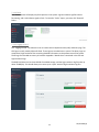
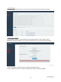
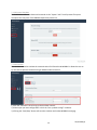
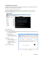
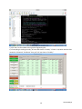
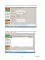
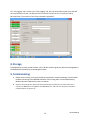
1
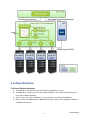
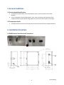
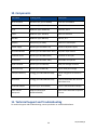
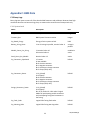
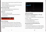
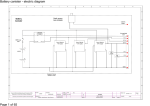
Operations Manual
Battery Monitoring System Model BMS100
Distributed by:
P: (757) 549-1494
AQ-OP-00008_B
Table of Contents
1. General Information ................................................................................................................................. 3
1.1 About This Manual .............................................................................................................................. 3
1.2 Disclaimers .......................................................................................................................................... 3
1.3 Contact Information............................................................................................................................ 3
2. Product Information.................................................................................................................................. 3
2.1 BMS100 Battery Monitoring System................................................................................................... 3
3. Safety Information .................................................................................................................................... 4
3.1 General Safety Information................................................................................................................. 4
4. Receipt of Equipment ............................................................................................................................... 5
4.1 Delivery Inspection.............................................................................................................................. 5
4.2 Actions................................................................................................................................................. 5
5. Service Conditions..................................................................................................................................... 6
5.1 Environmental Specifications.............................................................................................................. 6
5.2 Temperature Limits ............................................................................................................................. 6
6. Installation Procedure............................................................................................................................... 6
6.1 BMS Electrical Interfaces and Connections......................................................................................... 6
6.2 CAN Connector Cable .......................................................................................................................... 7
6.3 MODBUS/TCP ...................................................................................................................................... 8
6.4 Input Power Port ................................................................................................................................. 8
6.5 CAN Out Port ....................................................................................................................................... 8
7. Operation .................................................................................................................................................. 9
7.1 BMS100 Setup ..................................................................................................................................... 9
7.1.1 Hardware Installation................................................................................................................... 9
7.1.2 Web Page Operations .................................................................................................................. 9
7.2 BMS100 Testing and Analysis............................................................................................................ 15
7.2.1 Engineering_GUI Start-up Procedure ........................................................................................ 15
8. Storage .................................................................................................................................................... 19
9. Commissioning ........................................................................................................................................ 19
10. Components .......................................................................................................................................... 20
11. Technical Support and Troubleshooting ............................................................................................... 20
Appendix A: Frequently Asked Questions................................................................................................... 21
Appendix B: Glossary of Battery Terminology ............................................................................................ 22
Appendix C: BMS Data ................................................................................................................................ 23
C.1 Binary Logs ........................................................................................................................................ 23
1
AQ-OP-00008_B
C.1.1 System Level .............................................................................................................................. 23
C.1.2 String Level................................................................................................................................. 25
C.1.3 Module Level.............................................................................................................................. 27
C.2 CSV Data............................................................................................................................................ 29
C.3 Log Files............................................................................................................................................. 31
2
AQ-OP-00008_B
1. General Information
1.1 About This Manual
This manual is intended to provide technical information and safe practices regarding receiving,
installing, operating, and servicing the Aquion Energy BMS100 Battery Monitoring System. For complete
safety information, refer to the Safety Data Sheet (SDS) included with your product shipment.
NOTICE: Failure to follow the instructions in this document could result in fire, electric shock,
and/or other injury or damage.
1.2 Disclaimers
Estimated performance characteristics are based on testing conducted by Aquion Energy. Performance
may vary depending on use conditions and application. Aquion Energy makes no warranty, explicit or
implied, with this technical information. Contents are subject to change without notice.
1.3 Contact Information
Authorized Distributor
Solar Panels Plus, LLC.
2133 Smith Avenue
Chesapeake, VA 23320
(757) 549-1494
www.solarpanelsplus.com
2. Product Information
2.1 BMS100 Battery Monitoring System
The BMS100 Battery Monitoring System (hereafter “BMS100”) is used to collect data from all Battery
Modules in a string, store the data, and relay that data to the site controller.
3
AQ-OP-00008_B
3. Safety Information
3.1 General Safety Information
●
●
●
●
The BMS100 can communicate with up to 16 Battery Modules in a string.
The BMS100 can support up to 4 strings of Battery Modules, with each string composed of no
more than 16 Battery Modules.
Never connect more than 16 Modules in a string. Doing so may damage the BMS100.
Never connect the CANBUS with the BMS100 powered on. Doing so may damage the BMS100
and Module VIS boards.
4
AQ-OP-00008_B
4. Receipt of Equipment
4.1 Delivery Inspection
●
Immediately upon delivery, inspect all hard goods for signs of damage during transit. This may
be evidenced by damaged enclosures or connectors. Thoroughly document all instances of
product damage and make a claim with the carrier as soon as possible. Contact Aquion Energy
for further support.
The inside of the BMS should look like this.
4.2 Actions
●
●
If, upon delivery, equipment appears to be damaged, do not accept the shipment.
If you have accepted shipment and equipment in the shipment appears to be damaged, please
contact your appropriate support representative. For technical support contact information,
please see Section 11, Technical Support and Troubleshooting.
5
AQ-OP-00008_B
5. Service Conditions
5.1 Environmental Specifications
●
●
Environmental specifications must be followed to ensure maximum performance of AHI
batteries.
Units are designed to be stored/operated in a dry, clean environment with protection from
sunlight and water ingress. Material degradation can result from direct exposure to sunlight.
5.2 Temperature Limits
●
The BMS should be both stored and operated in the same environment as the Aquion batteries.
6. Installation Procedure
6.1 BMS Electrical Interfaces and Connections
6
AQ-OP-00008_B
B1
CAN OUT
P/N: Amphenol SineCo MN54PD02M005
PIN #
NAME
WIRE COLOR
1
Drain
Shield
2
V+
Red
3
VBlack
4
CAN_H
White
5
CAN_L
Blue
DESCRIPTION
CAN ground
+24 V Board Power
Return Board Power
CAN Bus High
CAN Bus Low
B2
MODBUS/TCP Connector
P/N: Mouser 523-RJF21B
PIN #
1
2
3
4
5
6
7
8
NAME
TX_D1+
TX_D1RX_D2+
Bi_D3+
Bi_D3RX_D2Bi_D4+
Bi-D4-
WIRE COLOR
White/Green
Green
White/Orange
Blue
White/Blue
Orange
White/Brown
Brown
B4
120VAC Power Input
P/N: Mouser 693-DD12.9321.1111
PIN #
L
N
G
DESCRIPTION
Tx Data+
Tx DataRx Data+
Bi-directional Data+
Bi-directional Data+
Rx DataBi-directional Data+
Bi-directional Data-
NAME
Line
Neutral
Ground
WIRE COLOR
Black
White
Green
6.2 CAN Connector Cable
P/N: MN57B4BD02Mxxx (xxx - cable length in decimeters)
This cable connects between the BMS100 B1 CAN OUT and the M100 J5 CAN IN.
7
AQ-OP-00008_B
6.3 MODBUS/TCP
P/N: Mouser 523-RJF21B
This port is used to connect the BMS100 to the site controller network via a standard cat5 ethernet
cable.
6.4 Input Power Port
P/N: Mouser 693-DD12.9321.1111
The input power comes from a standard IEC cable. There is a replaceable fuse between the input feed
and the power switch. The BMS100 must have constant supply voltage to ensure functionality.
6.5 CAN Out Port
P/N: Amphenol Sineco MN54PD02M005
This port connects between the BMS100 to the M100 Modules.
8
AQ-OP-00008_B
7. Operation
7.1 BMS100 Setup
The BMS100 is designed for simple hardware installation, software updating, and logging control. More
advanced operations are detailed in Section 7.2, BMS100 Testing and Analysis.
7.1.1 Hardware Installation
1.) Connect the male side of the DeviceNet cable to the CAN port. The female side of the DeviceNet
cable will connect to the M100 J5 CAN port. Make sure the DeviceNet cable string is properly connected
to the M100.
2.) Connect the MODBUS/TCP port to the Site Controller Network.
3.) Connect the 120 Vac Input cable and turn the switch on.
7.1.2 Web Page Operations
7.1.2.1 Logging In
To log into the BMS web interface, first find the unit's IP address written on the outside of the unit, next
to the ethernet port. Then, in a web browser, navigate to the IP address followed by "/bms" to log into
the web interface.
9
AQ-OP-00008_B
7.1.2.2 Changing the IP Address
Once logged in, you can generate a new IP address for your BMS unit.
1.) Click the “System” tab.
2.) Input the new IP address and netmask.
3.) Click “Update.”
The system will change the IP address and reboot to allow the change to take effect.
7.1.2.3 Status Display
The “Status Display” displays the real-time key systems values updated at .5Hz. These values are State of
Charge, System Output Voltage, System Input Current, and E-STOP State.
10
AQ-OP-00008_B
7.1.2.4 Faults
The “Faults” screen will display any faults present in the system. A green indicator signifies normal
functioning, and a red indicator signals a fault. To reset the “Faults” report, you must click “Reset All
Faults.”
7.1.2.5 Logging Control
The “Logging Control” tab allows the user to create comma-separated value (CSV) and binary logs. The
CSV logs are easily read by Microsoft Excel. These logs are recorded once a second. The binary logs are
compressed, high-resolution files containing detailed information on the performance of the system.
These logs are recorded once every 10 seconds. Appendix C details what is contained in the CSV and
high-resolution logs.
The BMS hard drive has less than 100 GB of available storage, and the high-resolution log files take up
about 70 MB/day. This should allow you to store up to 4 years’ worth of high-resolution log files.
11
AQ-OP-00008_B
7.1.2.6 View Logs
The “View Logs” tab allows the user to see all of the operations that have occurred on the BMS.
7.1.2.7 Firmware Update
As new software updates are released, Aquion will provide notification to the customer, and the
BMS100 will need to be updated. The “Firmware” tab allows the user to upload the latest firmware.
1.) Click “Choose File.” Browse to find the *.pkg file from Aquion Energy.
2.) Click “Upload Firmware.” The system will update the firmware and reboot the BMS.
12
AQ-OP-00008_B
7.1.2.8 System Shutdown
The BMS100 should be shut down and restarted via the “System” tab. This will prevent file system
corruption that may occur if the BMS100 experiences power loss.
7.1.2.9 Simulator
The simulator is used to simulate the communication of VIS boards and MODBUS. It allows the user to
try the controls protocol without having an M100 module connected.
1.) Click the “Simulator” tab to bring up the simulator controls.
2.) Either input your own configuration or click the “Use a prebuilt config?” checkbox.
3.) Clicking the “Start/Stop” button will start the simulator and initiate MODBUS messaging.
13
AQ-OP-00008_B
4.) Select an operation to perform.
5.) Click “Update Simulator” to initiate the operation.
14
AQ-OP-00008_B
7.2 BMS100 Testing and Analysis
The BMS100 comes pre-loaded with the Engineering_GUI designed to aid in the testing and analysis of
the BMS100 and M100 Battery Module performance.
7.2.1 Engineering_GUI Start-up Procedure
1.) SSH into the BMS100 via the Site Controller Network using MobaXterm freeware. MobaXterm
freeware can be downloaded at http://mobaxterm.mobatek.net/download-home-edition.html.
2.) Start a New Session
Under Basic SSH Settings, enter:
● Host Name: IP Address of the BMS100 unit (Found on outside of box next to ethernet port or set
by customer DHCP server)
● Username: bms
● Port: 22 (SSH sessions are
always done through Port 22)
3.) Click OK
● Password: voltage
● To change the password, type
“passwd” and follow
instructions to change the
password.
4.) Type “./engineering_gui”
15
AQ-OP-00008_B
5.) Click the X on the taskbar to bring up the Engineering GUI
6.) If everything is working correctly, all states will show as “Healthy.” If there is a problem with the CAN
network or VIS boards, Task Name “bms_task” will not show as “Healthy.”
16
AQ-OP-00008_B
7.) It is not recommended to manually stop or start tasks.
Eng neeringGUI(on bms8)
System
Processes J System State
E STOP
I
Data logging
BMS *1
I CSV logging I
Task Health
Process Management
ESTOP Reset
State
Task Name
Reset AllFaults
Cycle Rate
Healthy
bms_task
22Hz
Uptime
Od 4h 4m
Process Name
router_task
CPU
2% 4MB
Memory
7008
D
command
Stop
Battery voltage Sum
csv_loggi ng_task
Healthy
58Hz
Od 4h 4m
data_loggi ng_taslc
0%
2MB
7009
Stop
0.1v
data_logging_task
Healthy
56Hz
Od 4h 4m
csvJoggi ng_task
0%
2MB
7011
Stop
Ground Fautl Voltage
director_task
Healthy
11Hz
od 4h 4m
bms_task
0%
2MB
7017
Stop
-OV
failsafe_task
Healthy
10Hz
Od 4h 4m
director_task
0%
3MB
7034
Stop
State of Charge
loopback_estop_task
Healthy
20HZ
Od 4h 4m
failsafe_task
0%
2MB
7036
0.0 %
modbus_bridge_task
Healthy
20Hz
Od 4h 4m
loopback_estop_task
process_manager_task
Healthy
10Hz
Od 4h 4m
modbus_bridge_task
0%
3MB
7049
Stop
router_task
Healthy
10Hz
Od 4h 4m
statistics_task
0%
2MB
7050
Stop
VSM 'Witage
Director Status
Idle
statistics_task
Healthy
system_state_task
Healthy
Od 4h 4m
'"'
system_state_task
0%
0%
2MB
2MB
7039
7079
Stop
Stop
Stop
Od 4h 4m
12Hz
Soft Stop System
bms_task.cc:1329
Warning:Module *16 timed out (haven't recev
i ed a CAN packet for 2. 88023 se<onds).
Warn ng:M odule *16 t med out (haven't received a CAN packet for 2.37976 se<onds).
Il l
Eng neeringGUI(on bms8)
II
- II
System
Processes
ESTOP
ESTOP Reset
Reset All Fautls
Battery 'Witage Sum
0.1v
Ground Fautl Voltage
OV
System State
I Data Logging I BMS H1 I CSV Logging I
Spare -50..+50 rnA nput
I
Batt 'Witage Xducer
1 o.ovoc
Batt+ to Earth Voltage Xducer
1 o.ovoc
0.00000 mA
Batt- to Earth Voltage Xducer
I
LEM DHAB Current Sense High
1-252.0 Amps
LEM DHAB Current Sense Low
1-31.06 Amps
O.OVDC
State of Charge
0.0 %
VSM Votlage
System State of Charge
Di
System Voltage
0.0%
0.1v
rector Status
Idle
soft Stop System
System Current
1-0.03 Amps
Hardware Uptime
1247954 seconds
Software Uptime
114700 seconds
Charging Amp Hours
17
AQ-OP-00008_ 8
The “Data Logging” tab allows the user to create a log file to save all sensor data and calculations.
The “BMS #1” tab allows the user to select individual modules and view each one’s discrete state,
voltage, current, and temperature.
18
AQ-OP-00008_B
The “CSV Logging” tab is similar to the “Data Logging” tab, but only the predetermined sense data will
be saved instead of all data. The data will also be saved in CSV format so it can easily be read by
Microsoft Excel. The contents of this file are detailed in Appendix C.
8. Storage
The BMS100 can be safely stored between -10°C and 40°C without significant performance degradation.
The BMS100 should always be protected against water.
9. Commissioning
●
●
Before commissioning, the system should be inspected for mechanical damage, and the M100
modules connecting to the BMS100 should be in full working order. See the M100 Battery
Module Operations Manual for proper installation.
Aquion recommends that personnel experienced with the operation of power electronics
connect the BMS100 to the CANBUS and MODBUS/TCP, and that such operation should be
conducted with the power off.
19
AQ-OP-00008_B
10. Components
Part Name
Ordering Code
Description
NUC Computer
Macsales.com (P/N: 9780486)
Intel NUC D54250WYK
Enclosure
McMaster (P/N: 7812K23)
16”x16”x6” enclosure
Fuse
McMaster (P/N: 6978K734)
fuse 10 A, 250 V
Panel
McMaster (P/N: 7812K63)
panel for enclosure
DIN Rail
McMaster (P/N: 8961K15)
DIN rail, 11.5”
Adapter
Monoprice (P/N: 9466)
ethernet to USB adapter
Power Supply
Mouser (P/N: 709-SDR75-24)
24 Vdc 75 W power supply
AC Power Module
Mouser (P/N: 693-DD12.9321.1111)
AC power input module
Insulation Cover
Mouser (P/N: 693-0859.0076)
protector for AC input
Fusedrawer
Mouser (P/N: 693-4301.1401)
fuse holder for input AC
RJ45 Connector
Mouser (P/N: 523-RJF21B)
RJ45 pass-through connector
Connector Cap
Mouser (P/N: 523RJFC2B)
cap for RJ45 pass-through
Computer Memory
Newegg (P/N: N82E16820233588)
Corsair Vengeance Performance
8GB
Hard Drive
Newegg (P/N: N82E16820167144)
mSATA 120GB SATA MLC Internal
Solid State Drive
USB-CAN Adapter
Phytools (P/N: SYS-3204003)
SYSTEC USB-CANmodul2 adapter
Panel Mount
Receptacle
Amphenol Sinco (P/N:
MN54PD02M005)
panel mount DeviceNet receptacle
1 meter
11. Technical Support and Troubleshooting
For technical support and troubleshooting, contact your dealer or authorized distributor.
20
AQ-OP-00008_B
Appendix A: Frequently Asked Questions
What should I do if the bms_task is displayed as “unhealthy”?
This is usually caused by a failure of the BMS to communicate with the VIS boards. Check to make sure
the VIS boards are powered up and connected properly.
What should I do if the modbus_bridge_task is displayed as “unhealthy”?
This is usually caused by a failure of the BMS to set up the MODBUS/TCP bridge to the site control.
Check your system firewall to ensure it is not blocking IP permissions.
What should I do if the site controller is connected and set up as instructed, but it is still not
communicating with the site controller?
Check your system firewall to ensure it is not blocking the port that the BMS uses to communicate. The
BMS communicates on port 502.
21
AQ-OP-00008_B
Appendix B: Glossary of Battery Terminology
BMS – The BMS parses data from the VIS boards and processes it. The processed data is then stored
locally and can be relayed to a site controller on request via the MODBUS/TCP port.
CAN – Protocol used to communicate between the M100 VIS boards and BMS.
M100 – Palletized battery system containing 12 S-line Battery Stacks.
MODBUS/TCP – Protocol used to communicate between the BMS and site controller.
Open Circuit Voltage (OCV) – Potential between positive and negative terminal with no load applied.
State of Charge (SOC) – Represents present battery capacity as a percentage of rated capacity. SOC is
essentially the gas gauge of the battery from 0%–100%.
State of Health (SOH) – Represents the present capacity of the Module as a percentage of the
nameplate capacity.
VIS board – The VIS board measures the voltage, current, and temperature of a Battery Module and
relays that data to the BMS.
22
AQ-OP-00008_B
Appendix C: BMS Data
C.1 Binary Logs
Binary logs are meant to store all of the data the BMS measures and calculates. Because these highresolution data files can become large, they are meant to be stored for small time periods only.
C.1.1 System Level
Name
Description
Unit
HW_Rev
BMS System Hardware revision
integer
Firmware_Rev
BMS System Firmware revision
integer
Sys_Rated_Energy
Energy of entire system at BOL
kWh
Battery_String_Count
LV or HV strings in parallel, nominal value: 4
strings in
parallel
Module_Count_Per_String
LV nominal value: 16
HV nominal value: 1
modules in
series
Stack_Count_Per_Module
Nominal value: 12
stacks
Sys_Contactors_Populated
1: Present
0: Not available
Bit 0: Positive contactor
Bit 1: Negative contactor
Bit 2: Positive pre-charge contactor
Bit 3: Estop (Fault) relay
bitfield
Sys_Contactors_Status
1: On (closed)
0: Off (open)
Bit 0: Positive contactor
Bit 1: Negative contactor
Bit 2: Positive pre-charge contactor
Bit 3: Estop (Fault) relay
bitfield
Strings_Contactors_Status
1: On (closed)
0: Off (open)
Bits 15–0: Stacks 16–1. Bit value is logical
AND of all participating module contactors
and participating string-level contactors in
that string.
bitfield
Sys_Fault_Code
Logical OR of string fault codes
bitfield
Sys_Warning_Code
Logical OR of string warning codes
bitfield
23
AQ-OP-00008_B
Name
Description
Unit
Sys_SOC
Average across all usable battery strings
(-50%–150%)
percentage
Sys_SOH
Average across all usable battery strings
(0%–150%)
percentage
Sys_DC_Volts
Average across all usable battery strings
(average of the sums of Module volts in
string)
Vdc
Sys_DC_Current
Total across all usable battery strings
amps DC
Sys_Charge_Current_Limit
Total across all usable battery strings
amps DC
Sys_Discharge_Current_Limit
Total across all usable battery strings
amps DC
Sys_Charge_Power_Limit
Total across all usable battery strings
kW
Sys_Discharge_Power_Limit
Total across all usable battery strings
kW
Sys_Max_Module_Volts
LV typical range (0–60 Vdc)
HV typical range (0–720 Vdc)
Vdc
Sys_Max_Module_Volts_Location
Bits 12–8: String number (1-based)
Bits 4–0: Module number (1-based)
integer
Sys_Min_Module_Volts
LV typical range (0–60 Vdc)
HV typical range (0–720 Vdc)
Vdc
Sys_Min_Module_Volts_Location
Bits 12–8: String number (1-based)
Bits 4–0: Module number (1-based)
integer
Sys_Max_Module_Temp
Typical range -100–600 (i.e., -10°C–60°C)
degrees Celsius
Sys_Max_Module_Temp_Location
Bits 12–8: String number (1-based)
Bits 4–0: Module number (1-based)
integer
Sys_Min_Module_Temp
Typical range -100–600 (i.e., -10°C–60°C)
degrees Celsius
Sys_Min_Module_Temp_Location
Bits 12–8: String number (1-based)
Bits 4–0: Module number (1-based)
integer
Sys_AHR_Charge_MSB
Cumulative count of charging amp-hours
since reset upper bytes
amp-hours
Sys_AHR_Charge_LSB
Cumulative count of charging amp-hours
since reset lower bytes
amp-hours
24
AQ-OP-00008_B
Name
Description
Unit
Sys_AHR_Discharge_MSB
Cumulative count of discharging amp-hours
since reset upper bytes
amp-hours
Sys_AHR_Discharge_LSB
Cumulative count of discharging amp-hours
since reset lower bytes
amp-hours
Sys_KWHR_Charge_MSB
Cumulative count of charging kilowatt-hours
since reset upper bytes
kWh
Sys_KWHR_Charge_LSB
Cumulative count of charging kilowatt-hours
since reset lower bytes
kWh
Sys_KWHR_Discharge_MSB
Cumulative count of discharging kilowatthours since reset upper bytes
kWh
Sys_KWHR_Discharge_LSB
Cumulative count of discharging kilowatthours since reset lower bytes
kWh
C.1.2 String Level
These are the values on each string. There will be four of these data sets for a string of four.
Name
Description
Unit
String_Fault_Code
Added together...
bitfield
0: No fault
1: String comms fault (bit 0)
2: Module comms fault (bit 1)
4: Module ground fault (bit 2)
8: Module out of balance (bit 3)
16: Module over voltage (bit 4)
32: Module under voltage (bit 5)
64: Module over temperature (bit 6)
128: Module under temperature (bit 7)
256: String over current (bit 8)
512: String DC contactor fault (bit 9)
1024: String fuse fault (not implemented) (bit 10)
String_Warning_Code
Same as String_Fault_Code, but just in the
warning zone
bitfield
Is_String_Available
1: Yes
0: No
Boolean
25
AQ-OP-00008_B
Name
Description
Unit
Is_String_Contactor_Populated
1:Yes
0: No
Bit 0: Positive contactor
Bit 1: Negative contactor
Bit 2: Positive pre-charge contactor
bitfield
Is_String_Participating
1: Yes
0: No
Boolean
String_Modules_Populated
1: Yes
0: No
Bit 0: Module 1
bitfield
.
Bit 15: Module 16
String_Contactors_Status
1: On (closed)
0: Off (open)
Bit 0: Positive contactor
Bit 1: Negative contactor
Bit 2: Positive pre-charge contactor
bitfield
String_Module_Contactors_Status
1: On (closed)
0: Off (open)
Bit 0: Module 1
bitfield
.
Bit 15: Module 16
String_SOC
Average across all Modules in string
percentage
String_SOH
Average across all Modules in string
percentage
String_DC_Volts
Sum of all Module voltages in string
Vdc
String_DC_Current
Average across all Modules in string
amps DC
String_Charge_Current_Limit
Maximum allowable charging current
amps DC
String_Discharge_Current_Limit
Minumum allowable discharging current
amps DC
String_Charge_Power_Limit
Maximum allowable charging power
kW
String_Discharge_Power_Limit
Minumum allowable discharging power
kW
Max_Module_Volts
Maximum allowable Module voltage
Vdc
Max_Module_Volts_Location
Bits 4–0: Module number (1-based)
integer
Min_Module_Volts
Minimum allowable Module voltage
Vdc
26
AQ-OP-00008_B
Name
Description
Unit
Min_Module_Volts_Location
Bits 4–0: Module number (1-based)
integer
Max_Module_Temp
Typical range -100–600 (i.e., -10°C–60°C)
degrees Celsius
Max_Module_Temp_Location
Bits 5–4: Sensor number
Bits 4–0: Module number
bitfield
Min_Module_Temp
Typical range -100–600 (i.e., -10°C–60°C)
degrees Celsius
Min_Module_Temp_Location
Bits 5–4: Sensor number
Bits 4–0: Module number
bitfield
C.1.3 Module Level
These are the values recorded on every module. A system with N strings and M modules per string will
have M × N of these data sets.
Name
Description
Unit
Status_Code
TBD
bitfield
Fault_Code
0: No fault
1: Reset initialization state
2: Module comms fault
3: Module ground fault
4: Module out of balance
5: Module over voltage
6: Module under voltage
7: Module over temperature
8: Module under temperature
9: Module over current
10: Module DC contactor fault
11: Module fuse fault (not implemented)
12: Stack over current
bitfield
Warning_Code
Same as fault codes but just a warning
bitfield
Module_Voltage
Sum of all Stack voltages
Vdc
Module_Current
Sum of all Stack currents if LV; average of all
Stack currents if HV
amps DC
Module_Temperature
Average of temperature sensors
degrees Celsius
Stack1_Voltage
—
Vdc
Stack2_Voltage
—
Vdc
27
AQ-OP-00008_B
Name
Description
Unit
Stack3_Voltage
—
Vdc
Stack4_Voltage
—
Vdc
Stack5_Voltage
—
Vdc
Stack6_Voltage
—
Vdc
Stack7_Voltage
—
Vdc
Stack8_Voltage
—
Vdc
Stack9_Voltage
—
Vdc
Stack10_Voltage
—
Vdc
Stack11_Voltage
—
Vdc
Stack12_Voltage
—
Vdc
Stack1_Current
Stack 1 current
amps DC
Stack2_Current
Stack 2 current
amps DC
Stack3_Current
Stack 3 current
amps DC
Stack4_Current
Stack 4 current
amps DC
Stack5_Current
Stack 5 current
amps DC
Stack6_Current
Stack 6 current
amps DC
Stack7_Current
Stack 7 current
amps DC
Stack8_Current
Stack 8 current
amps DC
Stack9_Current
Stack 9 current
amps DC
Stack10_Current
Stack 10 current
amps DC
Stack11_Current
Stack 11 current
amps DC
Stack12_Current
Stack 12 current
amps DC
Temp_Sensor_Upper
Module temperature sensor number 1
degrees Celsius
Temp_Sensor_Lower
Module temperature sensor number 2
degrees Celsius
Temp_Sensor_PCB
Circuitboard temperature sensor
degrees Celsius
Positive_to_Ground_Voltage
Measured from positive bus bar to earth
ground (0: unused)
Vdc
28
AQ-OP-00008_B
Name
Description
Unit
DigOutputs_Status
1: On (closed)
0: Off (open)
Bit 0: Positive contactor
Bit 1: Negative contactor
Bit 2: Third output
bitfield
Inputs_Status
1: Asserted
0: Missing or unasserted
Bits 2–0: Input bits
bitfield
Module_SOC
Module state of charge
percentage
Module_SOH
Module state of health
percentage
Module_SerialNumber
Lowest 16 bits of 64-bit hardware serial
number
integer
Module_PCA_Number
Aquion-given PCA serial number
integer
Module_FW_Version
Version of the firmware currently running on
the BMS
integer
Cycle_Counter
Number of times the system has been cycled
integer
Fault_Counter
Number of times a fault has been triggered
integer
OverVolt_Event_Counter
Number of times the Module has exceeded
the over-voltage limit
integer
OverTemp_Event_Counter
Number of times the Module has exceeded
the over-temperature limit
integer
Module_Type
1: LV module with LV VIS
2: HV module with HV VIS
integer
C.2 CSV Data
CSV data is an abridged version of the binary log data. This allows the files to be much smaller and
stored for much longer time periods.
Name
Description
Units
HW_Rev
BMS System Hardware revision
integer
Firmware_Rev
BMS System Firmware revision
integer
Sys_Rated_Energy
Energy of entire system at BOL
kWh
29
AQ-OP-00008_B
Name
Description
Units
Battery_String_Count
LV or HV strings in parallel, nominal value: 4
strings in
parallel
Module_Count_Per_String
LV nominal value: 16
HV nominal value: 1
modules in
series
Stack_Count_Per_Module
Nominal value: 12
stacks
Sys_SOC
Average across all usable battery strings
(-50%–150%)
percentage
Sys_SOH
Average across all usable battery strings
(0%–150%)
percentage
Sys_DC_Volts
Average across all usable battery strings
(average of the sums of Module volts in
string)
Vdc
Sys_DC_Current
Total across all usable battery strings
amps DC
Sys_Charge_Current_Limit
Total across all usable battery strings
amps DC
Sys_Discharge_Current_Limit
Total across all usable battery strings
amps DC
Sys_Charge_Power_Limit
Total across all usable battery strings
kW
Sys_Discharge_Power_Limit
Total across all usable battery strings
kW
Sys_Max_Module_Volts
LV typical range (0–60 Vdc)
HV typical range (0–720 Vdc)
Vdc
Sys_Max_Module_Volts_Location
Bits 12–8: String number (1-based)
Bits 4–0: Module number (1-based)
integer
Sys_Min_Module_Volts
LV typical range (0–60 Vdc)
HV typical range (0–720 Vdc)
Vdc
Sys_Min_Module_Volts_Location
Bits 12–8: String number (1-based)
Bits 4–0: Module number (1-based)
integer
Sys_Max_Module_Temp
Typical range -100–600 (i.e., -10°C–60°C)
degrees Celsius
Sys_Max_Module_Temp_Location
Bits 12–8: String number (1-based)
Bits 4–0: Module number (1-based)
integer
Sys_Min_Module_Temp
Typical range -100–600 (i.e., -10°C–60°C)
degrees Celsius
Sys_Min_Module_Temp_Location
Bits 12–8: String number (1-based)
Bits 4–0: Module number (1-based)
integer
30
AQ-OP-00008_B
Name
Description
Units
Sys_AHR_Charge_MSB
Cumulative count of charging amp-hours
since reset upper bytes
amp-hours
Sys_AHR_Charge_LSB
Cumulative count of charging amp-hours
since reset lower bytes
amp-hours
Sys_AHR_Discharge_MSB
Cumulative count of discharging amp-hours
since reset upper bytes
amp-hours
Sys_AHR_Discharge_LSB
Cumulative count of discharging amp-hours
since reset lower bytes
amp-hours
Sys_KWHR_Charge_MSB
Cumulative count of charging kilowatt-hours
since reset upper bytes
kWh
Sys_KWHR_Charge_LSB
Cumulative count of charging kilowatt-hours
since reset lower bytes
kWh
Sys_KWHR_Discharge_MSB
Cumulative count of discharging kilowatthours since reset upper bytes
kWh
Sys_KWHR_Discharge_LSB
Cumulative count of discharging kilowatthours since reset lower bytes
kWh
C.3 Log Files
Log files keep track of operations that occur on the system such as when faults occur or data logging is
started.
31
AQ-OP-00008_B