1
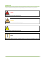
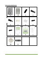
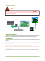
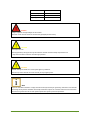
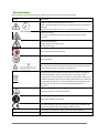
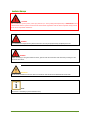
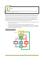
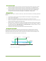
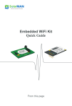
SolCasa A/T series Transformerless PV Grid-Connected Inverter User Manual Version 1.0 3XL SolarSolutions BV, Haarlemmerstraatweg 73E, 1165 MK Halfweg, the Netherlans Tel. +31 (0) 6 42 46 92 46 Email. [email protected] Web. http://www.3xl-solarsolutions.com Table of Contents ABOUT THIS MANUAL ...................................................................................................... 1 Compliances ................................................................................................................................................ 1 Inverters covered by this manual ................................................................................................................. 1 Storage of the Manual................................................................................................................................. 2 Symbols Used .............................................................................................................................................. 3 INTRODUCTION ................................................................................................................ 4 Features ...................................................................................................................................................... 4 View of the Inverter ..................................................................................................................................... 6 INSTALLATION .................................................................................................................. 8 Unpacking the inverter ................................................................................................................................ 8 Installation Notes. ..................................................................................................................................... 12 Typical Installation .................................................................................................................................... 15 Mounting the Inverter ............................................................................................................................... 16 OPERATION .................................................................................................................... 20 General ...................................................................................................................................................... 20 Dual MPPT power divide configuration ..................................................................................................... 24 INVERTER Wi-Fi and RS 485 CONNECTION CONFIGURATIONS .......................................... 25 Inverter connection RS 485 ........................................................................................................................ 25 Configuration using Wi-Fi (no internet) ..................................................................................................... 26 Configuration with Wi-Fi (inside the inverter) (internet) ............................................................................ 27 Configuration with Wi-Fi (inside the remote display) (internet) ................................................................. 28 MAINTENANCE ............................................................................................................... 29 Cleaning maintenance ............................................................................................................................... 29 General maintenance ................................................................................................................................ 29 VIEWING INFORMATION ................................................................................................ 30 Built in display (Graphical) ......................................................................................................................... 30 Local Monitoring with Smartphone or Tablet App ..................................................................................... 36 SolarMAN Portal........................................................................................................................................ 36 RS 485 connection ..................................................................................................................................... 36 APPENDIX....................................................................................................................... 38 Inverter Specifications ............................................................................................................................... 38 Connector details ....................................................................................................................................... 43 Cables ........................................................................................................................................................ 45 Inverter Fault Codes ................................................................................................................................... 46 Service ....................................................................................................................................................... 47 Contents ABOUT THIS MANUAL This manual follows the requirements of the European Low Voltage Directives, contains the safety instructions and conditions of acceptability for the end use system, which you must follow when installing, operating or servicing the unit. If ignored, physical injury or death may follow, or damage may occur to the unit. Read the instructions before you work on the unit. If you are unable to understand the dangers, warnings, cautions or instructions, contained in this manual then contact the manufacturer or an authorized service dealer before installation, operating or servicing the unit. Compliances Australia AS 4777.2 AS 4777.3 AS/NZS 3100:2009 Inc. A1 Germany VDE 0126-1-1/A1 VDE-AR-N4105 United Kingdom G83/1-1 G59-2 General IEC 62109-1 IEC 62109-2 EN 61000-6-2 EN 61000-6-3 EN 61000-3-3 EN 61000-3-11 EN 61000-3-2 Inverters covered by this manual SCA1500SNW SCA2000SNW SCA2500SNW SCA2800SNW SCA3000SNW SCA1500SN SCA1500SNW-S SCA1500SN-S SCA2000SN SCA2000SNW-S SCA2000SN-S SCA2500SN SCA2500SNW-S SCA2500SN-S SCA2800SN SCA2800SNW-S SCA2800SN-S SCA3000SN SCA3000SNW-S SCA3000SN-S SCT3200DDW SCT3680DDW SCT4000DDW SCT4600DDW SCT5000DDW SCT3200DD SCT3680DD SCT4000DNW SCT4600DD SCT5000DD SCT3200DNW SCT3680DNW SCT4000DD SCT4600DNW SCT5000DNW SCT3200DN SCT3680DN SCT4000DN SCT4600DN SCT5000DN About this Manual Page 1 Storage of the Manual The manual should be stored with other documents belonging to the installation and must be available to people authorized to work on the installation. The contents of this manual will be periodically updated or revised if necessary. Please check for revisions which can be downloaded from http://www.sldpower.com About this Manual Page 2 Symbols Used The following types of safety precautions and general information symbols are used in this manual. These important instructions should be followed during installation, operation and maintenance of the inverter. DANGER DANGER indicates a hazard with a high level of risk. WARNING WARNING indicates a hazard with a medium level of risk. CAUTION CAUTION indicates a hazard with a low level of risk. NOTICE NOTICE indicates additional information, emphasized contents or tips to help you solve problems or save time. About this Manual Page 3 INTRODUCTION Thank you for purchasing an SLD Power, grid connected inverter. Features of the SLD Power inverter are ahead of the field. Features Easy maintenance Inverters need preventative maintenance especially when they are mounted in an area where they are subject to dust, insects, spiders and other environmental problems that can cause the heat sinking to become clogged thereby reducing the heatsink efficiency. This inverter can be cleaned easily without the need to remove it from its mounts. Other inverters should be serviced by qualified personnel just to clean the fan and heatsink. Simple in its basic form There are three LEDs to give you information about the status of the inverter. An aural alarm can be connected to tell you if you have a non-self-clearing inverter failure. The inverter can be mounted in areas where other inverters cannot be as the inverter is not restricted by the ability to view a display when the remote display is used. There is no need for the internet, computer, wireless devices or smart phones in the basic configuration. Statistics are stored, however not displayed if you have no display. The inverter stores over 10 years of statistics and the last 5minor fault codes and the last 5 major fault codes. Major fault codes are not overwritten by minor fault codes. Note: Inverters are available with a display or no display. (Single MPPT models can be fitted with a two line display and Dual MPPT models can be fitted with a large display or a two line display.) Reliability Easy maintenance Internal components are sourced from major brands. Surge suppression devices are fitted on the AC side and the PV side to protect the electronics of the inverter. With a basic unit there is no display to fail or to fade. (Units are available with a two line display, graphical display and/or a remote display.) No buttons to fail on the unit without the display. No fan IP65 User functionality Remote aural alert and a local aural alert with a built in graphical display. Manual remote restart feature using the remote display Introduction Page 4 With the wireless option local monitoring is implemented using an application on your smartphone or tablet running either android or apple IOS. For PCs there is an optional application. Remote display allows local monitoring and can monitor multiple inverters up to 10 connected together via the RS 485. Wi-Fi can be fitted to the remote display or the inverter. (See the various Wi-Fi and display configurations.) Connect to the internet, with the Wi-Fi option installed, to monitor your inverter remotely via portal monitoring using a web browser on your smartphone, tablet or computer. Up to 4 inverters can be monitored on the same RS 485 bus via the portal monitoring Using the portal monitoring gives you graphical information, statistics and the ability to export “.csv files” and graphical information. Ability to set the grid over-voltage and under-voltage in some countries where grid supply is affected by long power line runs resulting in poor quality mains. Remote country areas can suffer with these problems. Optional remote display (with function buttons): The owner can mount the remote display in a position suitable for monitoring usually inside the home. Multiple inverters, up to 10 can be monitored from the remote display. The remote display can be used to send a restart command to your inverter. Connection of the remote display is done with RS 485. There is no need for an internet connection when this configuration is used. With the optional display the history statistics and the last 5 minor fault codes and 5 major fault codes can be displayed. Remote display has a built in aural alert for inverter faults that are non-self-clearing. The aural alert feature can be turned off selectively when multiple inverters are used or turned off if you have a continuous alarm. Using a remote display with Wi-Fi allows you to connect to the internet via wireless when your inverters are mounted outside your Wi-Fi connection range or where you have a poor Wi-Fi signal. Wi-Fi inside the remote display also allows local monitoring with your smart phone or tablet. (Android and Apple) An optional PC application is also available. Optional wireless: The optional Wi-Fi allows local and remote monitoring of the inverter. Wi-Fi can be installed in the remote display or the inverter. Locally you can login to the inverter using an application on a smartphone or tablet or an option PC application. With an internet connection you are able to remotely login to the inverter using SolarMAN* a portal monitoring system with a web browser on a PC, smartphone or tablet or with an application on a smartphone or tablet. *SolarMAN supplies the portal monitoring of your inverter when connected to the internet. Introduction Page 5 View of the Inverter . Graphical display Display control buttons Grid connection Protective earth connection PV isolation switch PV inputs MPPT 1 Pv inputs MPPT 2 Multifunction connector Wi-Fi antenna CAUTION CAUTION The AC power should only be applied if the PV isolation switch is off PV Isolation Switch OFF position will disconnect the solar panel input (PV array) from the inverter’s input. ON position will connect the solar panel input (PV array) to the inverter’s input. Switching on the PV input will power-up the processors inside the inverter that initialises, monitors and controls the inverter and the processor which controls the display and communication when PV ≥ 100volts. PV inputs There are 2 types of PV inputs. 1. 2. Single MPPT unit with a single input. (SCA 1500S, SCA 2000S SCA 2500S, SCA 2800S, SCA 3000S) Dual MPPT unit with two inputs. (SCT 3200, SCT 3680, SCT 4000, SCT 4600, SCT 5000) Introduction Page 6 Wi-Fi Antenna The built-in Wi-Fi is an option. It allows connection to a wireless router and/or local monitoring with a smartphone, tablet or PC. To allow monitoring with the smartphone or tablet you can download applications from the apple store or android store. PC monitoring is done with a web browser through the SolarMAN portal. (There is also an optional application available for the PC.) RS485 connector Used to connect to other inverters, VDE AR N4105 (power output controller) or a remote display. Note if a Wi-Fi unit is fitted this connector is removed. Multi-function connector Used to connect a remote display. If the distance to the remote display is within 10 meters then this port can be used to power the remote display. The port can also be used as an RS 485 connection. It also has an Aural alarm output, USB data input/output for later enhancements and a Ground and +5volts out. (See cables in the appendix.) Protective Earth connection The inverter must be connected to a building protective earth. This point is used to connect the protective earth. Grid connection No Display Status LED Meaning OFF: The PV array voltage is less than 100V. The inverter is in the standby mode. Standby mode is when the PV input voltage is below the Flashing GREEN: start-up voltage (PVfor the inverter to output AC power. Solid GREEN : The inverter is working normally. The inverter is in a fault condition. When there is a fault condition the LED will flash a code Flashing RED: which you can look up to tell you the type of fault. (See fault codes in Appendix) Some faults are self-clearing while the others require the attention of a serviceperson. With display Status LED POWER: RUN: FAULT: Introduction Meaning No light means the inverter PV array voltage input is less than 100Volts GREEN will mean that the PV array voltage is ≥100volts No light means the inverter is in the standby mode. YELLOW will mean that the inverter is connected to the grid and has output. No light means that there is no fault. RED will mean a fault has occurred. Page 7 INSTALLATION Unpacking the inverter Delivered Items ITEM A B C D E F G H I J K L M N Operation Description Number SolCasa Inverter 1 Mounting back-plate 1 AC Connector 1 Part number Model number M-S30 SD03 510 001 U (F) DC Connector +ve 1 or 2 PV-100508-F (model dependant) DC Connector -ve 1 or 2 PV 100508-M (model dependant) Wall plugs 4 Bolts for fixing back-plate 4 Communication Connector 1 Singatron 2CT3032-W04300 Multi-function Connector 1 Singatron 2CT3032-W08300 Warranty Card 1 Product manual 1 Test report 1 Quality Certificate 1 Barcode with serial number 1 Page 8 Picture of inverter and delivered items A Installation D C B A E A B C D E F G H I J K L M N Page 9 Overview of the installation DANGER After installation of a PV system, start-up of the unit (i.e. start of designated operation) is PROHIBITED until it is determined that the system meets all local and national regulations and has been inspected and approved by the local responsible authorities. Simplified concept of a Grid Connected Inverter Savings Technical rules and Intended use Installation must be suited to the on-site conditions and comply with local regulations and technical rules. SolCasa inverters are designed to comply with transformerless PV grid-connected inverter safety rules. Appropriate usage The SolCasa is a PV inverter that converts DC current of PV arrays into an AC output and feeds it into the public power grid SolCasa inverters can only be used as grid connected inverters. The inverter must only be connected to a public (local) power utility grid. PV string inputs are required to be floating they cannot be positive or negative earthed. If the PV array has an earth reference then this will not work with the SolCasa inverter. SolCasa inverters are transformerless. Please identify the environment of the mounting position and SolCasa inverter(s) carefully before installation. Installation Page 10 Site Indoor or outdoor Ambient temperature -20℃~+60℃ Humidity ≤90%, no condensation Degree of protection IP65 DANGER Danger to life due to high voltages in the inverter. •All work on the inverter must be carried out by qualified personnel only. CAUTION Hot surface on unit. •During operation, the upper case of the enclosure and the enclosure body may become hot. • Only touch the lower enclosure area during operation. CAUTION Possible damage to health as a result of the effects of radiation. •Do not stay closer than 20 cm to the inverter for any length of time. NOTE PV frames should be earthed to comply with the local requirements for grounding. SLD Power recommends connecting the PV frames and other electrically conductive surfaces in a manner which ensures continuous conduction to ground in order to have optimal protection of the system and personnel. Installation Page 11 Installation Notes. PV panel frame’s to be earth bonded. Inverter to have a mains isolation switch which must be clearly visible. It can be in the switchboard as long as the switch board is within 3 meters and is visible from the inverter. Check local regulations. The switchboard should have a lockable isolation switch with signage to inform persons that there are dual supplies feeding this switchboard. If it is installed in a system with sub switchboards there must be signage in the other switchboards to warn that there is power generating equipment other than grid mains supplying the switchboard. Examples of signage (Check local regulations) Installation Page 12 Explanation of Symbols This section gives an explanation of all the symbols shown on the inverter and on the type label. Symbol Explanation Danger to life due to high voltages in the inverter. There is residual voltage in the inverter. The inverter requires 30 minutes to discharge. • Wait 30 minutes before you work on components inside the inverter. Beware hot surface. The inverter can become hot during operation. Avoid contact during operation. Danger of high voltages Danger to life due to high voltages. Warning dual supply No access for unauthorized personal. TUV certification Warning that this inverter requires removal from the grid supply and the PV supply before any work is carried out on the inverter. Symbol for the marking of electrical and electronics devices according to Directive 2002/96/EC. Indicates that the device, accessories and the packaging must not be disposed as unsorted municipal waste and must be collected separately at the end of the usage. Please follow Local Ordinances or Regulations for disposal or contact an authorized representative of the manufacturer for information concerning the decommissioning of equipment. Protective conductor / Protective Earth (PE) Refer to the operating instructions CE mark is attached to the solar inverter to verify that the unit follows the provisions of the European Low Voltage and EMC Directives DC+ DC terminal, indicating the polarity of the connection as positive. DC- DC terminal, indicating the polarity of the connection as negative. Installation Page 13 Installation Warnings DANGER After installation of a PV system, start-up of the unit (i.e. start of designated operation) is PROHIBITED until it is determined that the system meets all local and national regulations and has been inspected and approved by the local responsible authorities. DANGER The installation and operation of SolCasa inverters can only be performed by qualified personnel. DANGER Before installing or using the SolCasa inverter, please read all instructions and cautionary markings in the technical documents. WARNING All electrical installations must be done in accordance with the local and National Electrical Code NOTE The device is intended for fixed installation only. Installation Page 14 Typical Installation PE Combiner Box MPPT-1 Fuses DC switches MPPT-2 Dual MPPT inverter Remote Display Local Login PE Local PC Wireless Router Aural alarm RS 485 Inverter Isolation Switch (lockable) PE Switchboard Remote Login Connection to the grid REV.1.0 DESCRIPTION SLD General Block Diagram Installation DATE 30-July-2013 BY PB Page 15 Mounting the Inverter Positioning: × × ü ü SLD inverters with the heatsink on the front can be mounted in areas that a tradition rear heatsink inverter cannot. Things to consider when mounting your inverter: Safety: Assess the occupational safety and health risks of the site Local regulations Indoor/ Outdoor Ambient environment. Proximity to your switchboard and to the PV arrays. Shaded Airflow around the heatsink. Mount vertically or tilted backward by max. 90° Adequate ventilation Determine cabling routes and lengths of runs. To determine cable size and also no cable loops that could have surge currents induced. How you will mount the inverter. Space for cabling running past and into the inverter. The surface the inverter will be mounted on. (non-flammable and able to support the weight of the inverter) Mounting of external devices e.g. isolation switches and combiner box. (PV isolation and fusing, surge protection, mains isolation, overload protection and additional surge protection.) Note: Inverter already has internal surge protection. PV inputs have MOVs and the AC has a combination of MOVs and a GDT. MOV = Metal Oxide Varistor GDT= Gas Discharge Tube Wiring sizes minimum 4 mm. Installer must calculate sizes according to length of runs and other parameters that will reduce the wiring rating. Calculations should be for less than 2 Ω for the grid mains cabling. (anti-islanding) For PV wiring loss should be less than 1% at normal power. Installation 2 Page 16 Check to make sure the installation site does not fall into any of the following conditions: If any do, then a risk assessment will be required. Unsafe due to assessment of occupational health safety risks. The ambient temperature is outside the range of tolerable ambient temperature +60°C, -13°F to +140°F). Higher than the altitude of 2,000 m above sea level. Above 2000m the inverter output will be de-rated. Close to flammable materials or areas where flammable materials are stored. Prone to be damaged by sea water. Prone to be flooded or high levels of snow falls. Close to corrosive gas or liquid (for example, locations where chemicals are processed or stored). Exposed to direct sunlight or in an enclosure exposed to direct sunlight. Little or no air flow Mounted on a surface without suitable fire/heat rating. Mounted on a wall without suitable load holding capacity. High humidity. Sites considered unsafe because of local regulations. Confined space without adequate airflow. Area subject to sand or dust storms. Exposed to steam, vapour, or water. Near antenna and/or data cables. Installation (-25°C to Page 17 Inverter back-plate 12mm 230mm 206mm Ø8 335mm 295mm 20mm Space required for mounting the inverter. Inverter dimensions and mounting requirements Model No. Prefix Dimensions LxW Space above Space below Space to the left Space to the right SCA1500SN 399mm 290mm 35mm 29mm 30mm 40mm SCA2000SN 399mm 290mm 35mm 29mm 30mm 40mm SCA2500SN 419mm 290mm 35mm 49mm 30mm 40mm SCA2800SN 419mm 290mm 35mm 49mm 30mm 40mm SCA3000SN 419mm 290mm 35mm 49mm 30mm 40mm SCT3200DD 540mm 325mm 80mm 125mm 47.5mm 57.5mm SCT3680DD 540mm 325mm 80mm 125mm 47.5mm 57.5mm SCT4000DD 540mm 325mm 80mm 125mm 47.5mm 57.5mm SCT4600DD 540mm 325mm 80mm 125mm 47.5mm 57.5mm SCT5000DD 540mm 325mm 80mm 125mm 47.5mm 57.5mm Space above, space below, space to the left, and space to the right all refer to the edges of the backing-plate. Before mounting the inverter plan your cable runs for entering into the inverter, cables that pass-by and other devices that need to be mounted near the inverter. Installation Page 18 When mounting the inverter be sure to leave enough space on the right hand side as when you place the unit on the wall you have to slide the unit to the left so the unit will lock in so it cannot be accidently knocked off the wall. Use the back-plate to mark the position of the holes on the surface that your inverter will be mounted on, paying attention that the inverter is vertical. Then with a suitable 10mm drill, drill the 4 holes to mount the inverter. The depth of the holes should be slightly greater than 5 cm. Insert the supplied expanding wall plugs into each hole. The inverter back-plate can now be mounted on the wall with the supplied bolts. WARNING WARNING indicates a hazard with a medium level of risk. Note: 1. If you are NOT mounting the inverter on a solid masonry wall then you will have to use suitable bolts to mount the inverter. Note: 2. Mounting of the inverter should be on a wall able to support the weight of the inverter. Note: 3. Mounting of the inverter should be on non-flammable material. Installation Page 19 OPERATION General Overview of the inverter The inverter is an electronic device that converts your solar panel array output to an AC voltage that can be fed into the local power grid. In order for this to happen there are strict regulations for the operation of the inverter to make it safe and compatible to the grid. Powering on (switching on) and powering off the inverter The inverter should have a PV ISOLATION SWITCH it is an option on the inverter or it will be located in the PV combiner box or mounted and labelled as the PV Isolation switch nearby the inverter. The inverter should have a MAINS ISOLATION SWITCH which will be located close to the inverter either by itself or in a switchboard. Before switching the inverter on; make sure the PV ISOLATION SWITCH is in the OFF position. This is not a strict rule, however for customers in Germany it will reduce the start-up time of the inverter. Powering on the inverter Switch the MAINS ISOLATION SWITCH to the ON position. Turn on the PV isolation switch. (See inverter start-up) Powering off the inverter Switch the PV ISOLATION SWITCH to the OFF position. Switch the MAINS ISOLATION SWITCH to the OFF position and the inverter will now be switched off. NOTICE NOTICE The inverter’s internal processors board is powered from the PV array. The processors supply will not start until the PV ≥100 Volts. Operation Page 20 Inverter start-up NOTICE NOTICE The inverter will not go to the run mode until the PV ≥150V The inverter will not go back to standby until after the PV voltage falls to PV ≤110V When you switch on the inverter (both AC and PV isolations switches closed) and the PV ≥100V then the display will light (remote and/or local) and the status of “Standby” will be displayed. Once the PV voltage rise to PV ≥150V a status of “Run Checks” will be displayed. You will also see a countdown on the display as the inverter progresses though checks to make sure the inverter is functioning correctly and that the grid voltage and frequency are within tolerance. If all is found to be ok then the inverter will start outputting AC and the status will go to “Running” The inverter will continue “Running” until PV≤110V or a fault occurs. 1. 2. 3. Standby: if the PV voltage is below the start-up voltage of the inverter or the PV voltage has not fallen below PV≤110 V after start-up. Running: if the PV voltage has been PV≥150V and now has not fallen below PV=110V. Fault: if a fault has been detected during the start-up connecting phase (this phase is an initialization, self-test and the testing of the grid and PV array) or during operation. If a fault occurs a fault code will be displayed. Fault codes are in the appendix. Simplified inverter operation Flow System initialisation Run checks Inverter safety self-test User initiated Standby Running Fault Fault has occured Outside PV min max values PV array voltage checks Setting mode Fault detected PV output is between PV min and max values Restart Save settings Installation Fault has recovered Page 21 PV VOLTAGE OPERATING RANGE for SLDPOWER INVERTERS PV voltage PV max for models SCA2500,SCA2800, SCA3000 and all SCT inverters (550Volts) 550 PV max for models SCA1500, SCA2000 (500Volts) 500 PV=500V PV=450V Note: After entering the status “running” if the PV voltage is within the boundaries of the RED line the Inverter will be connected to the grid and generating AC power 400 300 PV=150V The inverter will now goes through its initialization and safety checks before it goes to the “running” status PV=225V PV=200V 200 PV=175V PV=160V PV=150V PV=125V PV=120V When the PV voltage falls to PV<100V the inverter will go to sleep and the power light will go out. 100 PV=100V the Auxiliary Supply starts and the Inverter wakes up. The Power light will come on and the inverter is now waiting for the PV ≥ 150V to start. The inverter is now in Standby. When PV falls to PV=110V the inverter will go to the shutdown mode and the status will show “Standby” Time MPPT range 120V to 450V SCA1500 MPPT range 225V to 500V SCA3000 MPPT range 150V to 500V SCT3680, SCT4000 MPPT range 150V to 450V SCA2000 MPPT range 125V to 500V SCT3200 MPPT range 160V to 500V SCT4600 MPPT range 175V to 500V SCA2500, SCT5000 MPPT range 200V to 500V SCA2800 The bars represent the range of PV voltage that the MPPT works over for different types of inverters Installation Page 22 Inverter fault interruption 1. 2. If the inverter detects a short interruption it will measure the grid parameters and if they are within tolerance specified it will phase lock to the grid mains. “Running status is re-established quickly. If the inverter detects a long interruption it will measure the grid parameters and if they are within tolerance specified it will do several checks before phase locking to the grid mains. After a long interruption the inverter will take much longer to re-establish the “running” status Viewing information Information for your inverter is viewed in several ways. These will be described in the Viewing Information Chapter. From the built in display if fitted. Two types available. Two line display or a large graphical display. With a remote display installed. With a local PC, smartphone or tablet when the wireless option is installed in the inverter. With a PC, smartphone or tablet connected to the internet and the inverter is also connected to the internet via the wireless option and a wireless router. When the inverter is installed with no wireless and no display, information cannot be viewed, however the inverter will store 10 years of information internally and can be read anytime a display is connected. Only the last 5 minor fault codes and 5 major fault codes are stored in memory. For a list of major and minor fault codes see the Appendix. Information can be viewed simultaneously with the remote and local devices. De-rating of the inverter output The temperature of the heatsink is measured to insure that the inverter is protected. Above an ambient temperature of 45⁰C (note that at 45⁰C the temperature of the heatsink will be about 65⁰C at the normal output power of the inverter) the inverter will start to shut-down in a manner as shown in the diagram. The unit will not start until the heatsink temperature rises above -20⁰C. De-rating starts occurring at 65 ⁰C % of Normal Power Output (Pn) T2 100 Pn 80 At 90 ⁰C the Inverter Shutsdown 60 50% Pn 40 T1 -40 -30 T3 At 75 ⁰C the inverter remains at .5 Pn until shutdown at 90 ⁰C 20 -20 -10 0 10 20 30 40 50 60 70 80 T4 90 Heat Sink Sensor Temperature ⁰C T1 = -20⁰C T2 = 65⁰C T3 = 75⁰C T4 = 90⁰C Installation Page 23 Dual MPPT power divide configuration Dual MPPT models limit the maximum input power from each PV input in order to protect the inverters internal bus voltage from being exceeded. To achieve this aim the maximum input power from each PV array is limited in a ratio which is set under the parameters configuration menu. When setting up your PV arrays please pay attention to this table and select the appropriate Power Divide Ratio from the parameters menu.. Power Divide Ratio PV1 input PV2 input 30 70 35 65 40 60 45 55 50 50 55 45 60 40 65 35 70 30 Installation SCT3200DNW 960 2240 1120 2080 1280 1920 1440 1760 1600 1600 1760 1440 1920 1280 2080 1120 2240 960 Maximum input (PV1) W (PV2) W SCT3680DNW SCT4000DNW SCT4600DNW 1104 2576 1200 2800 1380 3220 1288 2392 1400 2600 1610 2990 1472 2208 1600 2400 1840 2760 1656 2024 1800 2200 2070 2530 1840 1840 2000 2000 2300 2300 2024 1656 2200 1800 2530 2070 2208 1472 2400 1600 2760 1840 2392 1288 2600 1400 2990 1610 2576 1104 2800 1200 3220 1380 SCT5000DNW 1500 3500 1750 3250 2000 3000 2250 2750 2500 2500 2750 2250 3000 2000 3250 1750 3500 1500 Page 24 INVERTER Wi-Fi and RS 485 CONNECTION CONFIGURATIONS Inverter connection RS 485 In this configuration the monitoring of the inverter is via a remote display mounted in a place suitable for the customer. E.g. Inside the home mounted on a wall. To add more inverters to this configuration simply daisy chain the inverters using the RS 485.Monitoring of up to 10 inverters with the remote display. Inverter connection RS 485 Note: Inverters can be added using RS 485 The controller box is only required in countries that follow the German standard VDE-AR-N4105 Remote Display 4105 Controller box RS 485 Operation RS 485 Page 25 Configuration using Wi-Fi (no internet) An inverter which is fitted with a Wi-Fi module can be monitored using an application on a smartphone or tablet. Applications are available for Android and iOS. Download from the Apple store, Android store or http://www.solarmanpv.com/en-us/mobileapp.html. There are two applications: 1. 2. An application to configure and diagnose your Wi-Fi module. An application to monitor your inverter(s) locally or remotely. After downloading the SolarMAN applications install the applications. To configure your wireless device follow the SolarMAN manual supplied.with the wireless option. You should now be ready to login to your inverter using the SSID and password that you set. You are now ready to monitor your inverter locally Note: You can monitor the inverter using an optional PC application. Connecting to the inverter using Wi-Fi (No internet) Local PC with optional software Note inverters can be added using RS 485 Local Smartphones Tablet devices Installation 4105 Power Output Controller box RS 485 The Power output controller box is only required in countries that follow the German standard VDE-AR-N4105 Page 26 Configuration with Wi-Fi (inside the inverter) (internet) Wireless connection with remote monitoring via Note: Inverters can be added Solarman Portal using RS 485 Remote PC Wireless router Optional Remote display RS 485 RS485 Smartphones Tablet devices Note: The Wifi in the remote display can have the advantage of being closer to your internet wireless router. 4105 Power output Controller box The power output controller box is only required in countries that follow the German standard VDE-AR-N4105 In this configuration you can monitor your inverter locally on the remote display or via the internet and the SolarMAN portal. To login remotely you can use a web browser or an application on your device. Setup of this mode requires following the SolarMAN manual and establishing an account on the SolarMAN portal site. Up to 4 inverters can be monitored thru the SolarMAN portal, if they are all on the one RS 485 bus Up to 10 inverters can be monitored thru the remote display if they are on the same RS 485 bus. Installation Page 27 Configuration with Wi-Fi (inside the remote display) (internet) Wireless connection with remote monitoring via Solarman Portal and a remote display with built-in Wi-Fi Remote PC Wireless router Remote Display with built in Wi-Fi PC Local Login RS 485 RS 485 Smartphones Tablet devices Note: The Wifi in the remote display can have the advantage of being closer to your internet wireless router. 4105 Power Output Controller box The power output controller box is only required in countries that follow the German standard VDE-AR-N4105 In this configuration you can monitor your inverter(s) locally on the remote display, smart phone, tablet, local PC (with optional software) or via the internet and the SolarMAN portal. To login remotely you can use a web browser or an application on your device. Setup of this mode requires following the SolarMAN manual and establishing an account on the SolarMAN portal site. Up to 4 inverters can be monitored thru the SolarMAN portal, if they are all on the same RS 485 bus Up to 10 inverters can be monitored thru the remote display if they are on the same RS 485 bus. Installation Page 28 MAINTENANCE Cleaning maintenance With the unit OFF: (See powering off the inverter) Switch off the unit and wait 30 minutes. After the heat sink is cooled down the heat sink fins on the front of the inverter can be cleaned using a long bristled brush. If necessary use warm soapy water to clean. If any problems are found please contact your qualified service person. General maintenance Maintenance can be carried out by a qualified service person. If any repairs are required then only a qualified service person should do the repairs. With the unit OFF: (See powering off the inverter) Visually check cables, plugs, connectors, switches and connections to the inverter to make sure there are no damaged or deterioration of the covers and insulation or signs of heat damage around connectors. After the heat sink is cooled down the heat sink fins on the front of the inverter can be cleaned using a long bristled brush. If necessary use warm soapy water to clean. Check the operation of the switches. PV isolation and the inverters isolation sampling circuit breaker. (Installed by inverter installer) Shutdown the inverter by opening both the Grid mains isolation switch and the PV isolation switch. You can now turn on the PV isolation switch. If there is sufficient sun light the unit will come up in “standby”. Close the Grid mains isolation switch and you should see the inverter run the “run checks” before the inverter goes to the “running” status. Notes: 1. 2. When doing checks for the PV and Grid isolation switches there needs to be sufficient sunlight that the PV array is ≥150 volts. German models will need 10 minutes before the inverter goes to the “running” status unless they turn the Grid isolation switch on first. Check the fault log to determine if there have been any faults that should be diagnosed as to why they are happening. (See Display flowchart and then look at the fault codes in the Appendix) The inverter can now be left operating if no problems were found. Installation Page 29 VIEWING INFORMATION Built in display (Graphical) The graphical display is an option that can display information stored in the inverter. The information is displayed in tabular and graphical formats. The password for the user menu is 2353 The Screen S:Running 17:30:00 Information displayed on the screen PV input voltage MPPT1 MPPT2 Grid V AC Grid I AC PV input current Current power output Graphical display of selected data Power generated today Total power generated by the unit Inverter status or selection S:Running 17:30:00 The screen also has four buttons that controls the information you can display. ENT ESC POWER RUN FAULT Viewing Information Select an item or menu Steps you back one level of a menu Moves up a menu item or increment Moves you down a menu item or decrement Green when the unit Powers up PV ≥100Volts Yellow when the inverter is connected to the grid Red if the inverter is in a fault condition. Page 30 Built-in display Flow Chart (graphical) Viewing Information Page 31 Built-in two line display The two line display has one key the ENT button. To manipulate the display either press the ENT key with a short press or for longer than two seconds. The USER password is 2353 Viewing Information Page 32 Viewing Information Page 33 Remote Display The remote display is functionally the same as the Graphical Display except it has the ability to monitor up to 10 inverters. 1. 2. 3. 4. 5. 6. 7. 8. It has its own built in Aural alarm. A remote reset can be sent to any of the monitored inverters. Alarms from individual inverters can be turned off and on The built in Alarm can also be silenced. The remote display can be powered from an inverter or by a local power supply. The remote display can have an optional Wi-Fi. With the Wi-Fi in the remote display there is no need to have a Wi-Fi in your monitored inverters. When the Wi-Fi is fitted in the remote display it is usually closer to a Wi-Fi access point so as you system can be monitored from the internet. Viewing Information Page 34 Remote Display Flowchart Status line displays: ID nn, Status, date/time/ parameter change, Remote display alarm on/off* Top Level The graphical displays shows statistics for the ID being displayed in the status line. Top level cycles thru connected IDs. 10 seconds /ID ID 01 SN16xxxxxx Note: When an individual inverter is selected alarms from other inverters will still show on the fault light and as an Aural alarm * ENT ID 02 SN16xxxxxx Allows display and control of selected inverter See graphical Display flow chart. When the local alarm has been silenced an “X” on the end of the status line will be displayed when the screen is at the top level ESC will take you back to the Top Level A maximum of 10 inverters can be monitored. The inverters must have sequential IDs i.e. 01-10 ID n SN16xxxxxx The display will return to the top level after 40 seconds if no key is pressed. Energy Total Aural alarm 1 second tone every 2 minutes. ENT Alarm set ENT Wi-Fi Status ENT Baud rate select Viewing Information Alarm on Alarm off* Wi-Fi connected IP xxx.xxx.xxx.xxx or NA 19200 9600 Page 35 Local Monitoring with Smartphone or Tablet App Local monitoring is available with the wireless option installed in the inverter or remote display. In order to monitor using your smartphone or tablet you first need to download the SolarMAN application from the apple or android stores, and install them. You can now login to your inverter locally by connecting to the SSID of your inverter Wi-Fi and entering your password. Note: You are able to change the SSID and password with the SolarMAN tools application that is available for download as well. It can also be changed using a PC login. The IP address for the Admin of your wireless device is 10.10.100.254. You will see a screen that you can now enter the user name and the password. User name is admin and the password is admin. SolarMAN Portal With an internet connection you can setup a portal connection with SolarMAN. To setup an account you will need to follow the supplied Wi-Fi handbook. Then go to the SolarMAN portal http://www.solarmanpv.com/portal/ website. At the website select register and follow the instructions. Once you have setup your account you can then login to your account and monitor your inverter/s from anywhere you can connect to the internet. Monitoring can be via the smartphone or tablet applications or from a PC using a web browser. When you connect using the web browser you are able to download graphical files and .csv files. RS 485 connection NOTICE The RS 485 connection should be installed by a person with knowledge of computers and RS 485. 1. 2. 3. The RS 485 connection is used for connecting multiple inverters together. Connect a remote display. Connect a VDE AR N4105 power output controller box. On a RS 485 bus each device has its own unique identification number ID. The remote display since it is a controller has the ID 00. By default all inverters are set to an ID 01. If multiple inverters are used then through the remote or local display, the ID of an inverter can be changed. RS 485 ID range is 00-31. 1. ID 00 is used for the remote display or a controller like a PC 2. The remote display monitors a maximum of 10 inverters. The inverters needs to be addressed in the range 01 -10. 3. If your inverter has a VDE AR N4105 power output controller box attached to the RS 485 bus its ID will be ID 29(this is a reserved address) Viewing Information Page 36 Multiple inverter Connection Multiple inverter connection Remote Display 4105 Power Output Controller box ID 29 Viewing Information RS 485 ID 02 RS 485 ID 01 RS 485 ID 00 Page 37 APPENDIX Inverter Specifications Single MPPT models Model SCA1500SNW SCA2000SNW SCA2500SNW SCA2800SNW SCA3000SNW Max. PV-generator power 1750W 2250W 2750W 3050W 3250W Max. DC voltage 480V 480V 550V 550V 550V Start voltage PV Input Operating Voltage Range 150 V 150 V 150 V 150 V 150 V 110-450V 110-450V 110-550V 110-550V 110-550V MPPT voltage range 120-450 V 150-450 V 175-500 V 200-500 V 225-500 V Turn-off DC voltage 110 V 110 V 110 V 110 V 110 V Max. DC current Absolute Maximum Total PV Array Short Circuit Current Number of DC connections 15 A 15 A 15 A 15 A 15 A 18.8 A 18.8 A 18.8 A 18.8 A 18.8 A 1 1 1 1 1 Number of MPPT trackers 1 1 1 1 1 DC-connection MC4 or Amphenol Helios DC-switch Optional DC Input Data AC Output Data AC connector Plug-in connector (Amphenol S30 SD03 S10 001 U (F)) Power connection Single phase Nominal AC power 1500W 2000W 2500W 2800W 3000W Max. AC power 1650W 2150W 2700W 3000W 3200W Nominal AC voltage 180 - 270V Nominal AC frequency 50 / 60 Hz Nominal AC current 6.5A 8.7A 10.9A 12.2A 13.0A Max. AC current 7.2A 9.3A 11.7A 13.0A 13.9A Power factor >0.99 THD of AC current ﹤3% ﹤3% ﹤3% ﹤3% ﹤3% Power consumption at night ≈0W ≈0W ≈0W ≈0W ≈0W Power consumption at standby <5 W <5 W <5 W <5 W <5 W Max. efficiency 97.0% 97.0% 97.2% 97.2% 97.4% Euro efficiency 96.0% 96.2% 96.3% 96.3% 96.5% MPPT adaptation efficiency >99.5% Efficiency Appendix Page 38 Model SCA1500SNW SCA2000SNW SCA2500SNW SCA2800SNW SCA3000SNW Safety Equipment DC insulation monitoring Integrated Earth fault protection Integrated Mains monitoring Integrated Earth fault current monitoring Integrated Islanding effect monitoring Integrated AC I/P surge protection MOVs and GDT integrated GDT= Gas Discharge Tube PV I/P surge protection MOVs integrated MOV=Metal Oxide Varistor General Data LCD display Two Line Display (Optional Remote Display) Communication Wi-Fi , RS485 Multi-function connector RS 485, USB data(future enhancement), Aural alarm o/p, +5volts o/p, Sgnd. RS 485 connector RS 485 signals Dimensions (L*W*H) [mm] 399x290x118 419x290x118 Net weight [kg] 15kg 16kg Installation environment Indoor / outdoor Mounting information Wall mount Operating temperature -20℃ to +60℃(above 45℃ progressive de-rating occurs) Relative humidity 95%, no condensation Site altitude Up to 2000m above sea level before de-rating occurs IP protection type IP 65 Isolation type Transformerless Cooling concept Free convection Noise level <25 dBA . Appendix Page 39 Dual MPPT models Model SCT3200DNW SCT3680DNW SCT4000DNW SCT4600DNW SCT5000DNW Max. PV-generator power 3460W 4000W 4350W 4800W 5350W Max. DC voltage 550V 550V 550V 550V 550V Start voltage 150 V 150 V 150 V 150 V 150 V PV Input Operating Voltage Range 110-450V 110-450V 110-550V 110-550V 110-550V MPPT voltage range 125-500 V 150-500 V 150-500 V 150-500 V 150-500 V Turn-off DC voltage 110 V 110 V 110 V 110 V 110 V Max. DC current 12 A 15 A 15 A 15 A 15 A Absolute Maximum Total PV Array Short Circuit Current 15 A 18.8 A 18.8 A 18.8 A 18.8 A Number of DC connections 2 2 2 2 2 Number of MPPT trackers 2 2 2 2 2 DC-connection MC4 or Amphenol Helios DC-switch Optional DC Input Data AC Output Data AC connector Plug-in connector (Amphenol S30 SD03 S10 001 U (F)) Power connection Single phase Nominal AC power 3200W 3680W 4000W 4600W 5000W Max. AC power 3400W 3800W 4200W 4600W 5200W Nominal AC voltage 180 - 270 V Nominal AC frequency 50 / 60 Hz Nominal AC current 13.9A 15.7A 17.4A 20.0A 21.7A Max. AC current 14.8A 16.5A 18.3A 20.0A 22.6A Power factor 0.95 leading ~ 0.95 lagging THD of AC current ﹤3% ﹤3% ﹤3% ﹤3% ﹤3% Power at night ≈0W ≈0W ≈0W ≈0W ≈0W Power at standby <5 W <5 W <5 W <5 W <5 W Max. efficiency 97.4% 97.5% 97.5% 97.6% 97.6% Euro efficiency 96.5% 96.8% 96.8% 97.0% 97.0% MPPT adaptation efficiency >99.5% Efficiency Safety Equipment DC insulation monitoring Integrated Earth fault protection Integrated Mains monitoring Integrated Earth fault current monitoring Integrated Islanding effect monitoring Integrated AC I/P surge protection MOVs and GDT integrated GDT= Gas Discharge Tube PV I/P surge protection MOVs integrated MOV=Metal Oxide Varistor Appendix Page 40 Model SCT3200DNW SCT3680DNW SCT4000DNW SCT4600DNW SCT5000DNW General Data LCD display Yes, Remote Display (optional) Communication RS 485, Wi-Fi (optional) Multi-function connector RS 485, USB data(future enhancement), Aural alarm o/p, +5volts o/p, Sgnd. RS 485 connector RS 485signals Dimensions (L*W*H) [mm] 540x325x130 Net weight [kg] 21 Installation environment Indoor / outdoor Mounting information Vertical or Horizontal Operating temperature -20℃ to +60℃(above 45℃ progressive de-rating occurs) Relative humidity 95%, no condensation Site altitude Up to 2000m above sea level before de-rating occurs IP protection type IP 65 Isolation type Transformerless Cooling concept Free convection Noise level <25 dBA Appendix Page 41 Wi-Fi Option Specifications General Max. number of inverters 1 Remote communication WiFi(802.11 b/g/n) WiFi frequency 2.412GHz-2.484GHz WiFi communication range 400m in outdoor open area without obstruction Status display 3 LEDs Data access WiFi point-to-point Remote server WiFi transmitting power 802.11b/g/n:+20dBm/+18dBm/15dBm(Max) Configurable by users WiFi receiving sensitivity 802.11b: -89dBm 802.11 g: -81dBm 802.11 n: -71dBm External antenna External:I-PEX connector Internal:Board antenna Data collection intervals 5minutes(Default) 1-15minutes(Optional) Data interface UART : 12000bps - 57600bps/RS485/RS232 Memory 1-16M (Optional) Preferences setting Web Server Firmware updates Wireless Electrical Working voltage DC 3.3V/DC 5V/DC 5.5-25V (+/-5%) Working current 170mA~300mA(@3.3V) Environmental Operating temperature -25~+85°C Storage temperature -40~+125°C Storage humidity <40% Operating humidity 10%-90% Relative humidity, no condensation Physical Dimension(L*W*H) 25mm*40mm*3mm Other Warranty 5 years Certificates FCC,CE Appendix Page 42 Connector details AC connection The inverter is equipped with a water-proof direct plug-in connector for the AC connection at the bottom of the inverter. Plug supplied. 2 AC cable should be copper 4 mm minimum. Calculations are required to determine the resistance between the switchboard and the inverter which is required to be less than 2Ω. This is required for the anti-islanding to function correctly. 2 2 The AC connector supplied is able to take wire sizes 2.5 mm to 6 mm. The connector type is an Amphenol S30 SD03 S10 001 U (F) L AC Plug Earth Live Neutral N Rear view Appendix Page 43 Amphenol Helios H4 connector CAUTION 1) The connector must be isolated and disconnected from the power supply during the assembling or disassembling process. 2) Do not disconnect under load. 3) The use of PV cable is recommended. 4) The use of tin plated cable is recommended. 5) The connectors are IP68 rated Multifunction connector Singatron 2CT3032-W08300 .1 7 6 2 8 5 4 3 Pin Assignments Plug Front View 1:RS 485 2: RS 485 + 3:+5V 4:USB D- 5:USB D+ 6:SGND 7:Alarm Output 8:Not connected Pin 3 +5 volts can supply a maximum of 500mA. RS 485 connector Singatron 2CT3032-W04300 4 .1 3 2 1: Not connected 2: RS 485 + 3: RS 485 4: Not connected Pin Assignments Plug Front View Appendix Page 44 Cables Multi function cable RS 485 RS 485 + +5V . 7 6 1 RS 485 - 2 2 RS 485 + 3 3 +5V 4 4 USB D- 5 5 USB D+ 6 6 7 7 8 8 1 2 8 5 1 USB D- 3 4 Pin Assignments Plug Front View USB D+ SGND Alarm Output Not connected SGND Alarm Output Not connected RS 485 cable RS 485 + . 4 3 2 RS 485 connector to RS 485 connector 2 RS 485 + 1 4 .1 2 3 2 Pin Assignments Plug Front View RS 485 - 3 3 RS 485 - Pin Assignments Plug Front View RS 485 cable 6 8 5 RS 485 + .1 7 4 1 Multi function connector to RS 485 connector 2 RS 485 + 3 Pin Assignments Plug Front View RS 485 - SGND 2 6 3 RS 485 - Cable shield Note: 1. 2. 3. Cables that are installed outside should have a UV stabilised outer sheath. Cables should be twisted pairs with a shield. The multi-function cable is normally used with the remote display, it can also be used for the remote alarm or RS485 connection. A future enhancement will be also used as a USB port to update firmware. Appendix 4 .1 3 2 2 Page 45 Pin Assignments Plug Front View Inverter Fault Codes Fault code 1 Description Bus voltage: overvoltage 2 Grid current: overcurrent 3 PV1 current: overcurrent 4 PV2 current: overcurrent 5 PV1 reverse current: overcurrent 6 PV2 reverse current: overcurrent 7 IGBT driver protection 8 DC offset on AC output exceeded 9 Leakage current: overcurrent 10 Over temperature 11 Grid voltage: abnormal 12 Grid frequency: abnormal 13 Frequency change: abnormal 14 EEPROM fault 15 FLASH fault. 16 A to D offset abnormal 17 Earth fault 18 Grid LN transposition 19 MOV fuse fault 20 Insulation resistance fault 21 RCMU fault 22 AC relays fault 23 DSP-DSP communication error 24 ARM-DSP communication error 25 COMM-Display CPUs communication error 26 WIFI communication error 27 COMM CPU Program checksum error 28 Display CPU Program checksum error 29 Master CPU Program checksum error 30 31 Slave CPU Program checksum error PV1 voltage sampling circuit fault 32 PV1 current sampling circuit fault 33 PV2 voltage sampling circuit fault 34 PV2 current sampling circuit fault 35 Bus voltage sampling circuit fault 36 Grid frequency sampling circuit fault 37 Grid voltage sampling circuit fault 38 Grid current sampling circuit fault 39 Leakage current sampling circuit fault 40 Temperature sampling circuit fault Appendix MAJOR Hardware Grid problems or Operating temperature faults (Recoverable) Any fault from this group will be listed in Major Faults table MINOR Any fault will be listed as Minor Hardware MAJOR Hardware AC output connection problem MAJOR MAJOR MAJOR Hardware MAJOR Connection error or hardware fault MINOR Program corruption: update firmware MAJOR Sampling circuit fault Master and Slave DSP results are different. MAJOR No earth connection Page 46 Service Warranty SLD Power Co., Ltd offers a 5 years warranty service for SolCasa series inverter. The warranty period is from the date of installation. However the longest period will not exceed 66 months from the date of delivery of the inverter. During the warranty period, SLD Power Co., Ltd guarantees normal function of the SolCasa inverter. If there are faults within our responsibility, we will provide maintenance free of charge. During the warranty period, if inverter fails or constantly has an error code, please contact your dealer or installation contractor. The followings are not included in the scope of warranty: SolCasa inverter is used for other than the purpose it is designed for. Installed incorrectly or not conforming to regulations. Improper usage Modification of the inverter without authority; Damage because of external factors or the majeure force(such as lightning, over-voltage, bad weather, fire, earthquake, tsunami and so on); Poor ventilation; Not installed to comply with relevant safety regulations; Transportation damage. Technical inquiry If you have any technical problems concerning our products, you can contact us via: www.sldpower.com service. We require the following information in order to provide you with the necessary assistance: Model of your inverter Serial number Type and number of PV modules connected Displayed fault messages from the inverter fault history. Both major and minor faults. Country the inverter is installed in. Agent from which the inverter was purchased. Appendix Page 47 Contact details Wuxi SLD Power Technology Co., Ltd. ADD: NO.201, Jinshan Road, Jiangyin, Wuxi 214400, China. Tel: +86 510 8699 0086 Fax: +86 510 8160 2143 Email: [email protected] Website: www.sldpower.com European local service center 3XL SolarSolutions BV ADD: Haarlemmerstraatweg 73E, 1165 MK Halfweg, The Netherlands Tel: +31 (0) 6 42 46 92 46 Email: [email protected] Website: www.3xl-solarsolutions.com Appendix Page 48