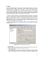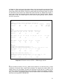
1
StOCNET
An open software system
for the advanced statistical analysis of social networks
User’s Manual
version 1.7
February 2006
Groningen: ICS / Science Plus
http://stat.gamma.rug.nl/stocnet/
Peter Boer
Mark Huisman
Tom A.B. Snijders
Christian E.G. Steglich
Lotte H.Y. Wichers
Evelien P.H. Zeggelink
Contents
0
Contents ................................................................................................................................... 2
Software .................................................................................................................................. 3
1
Introduction............................................................................................................................. 4
2
The program............................................................................................................................ 5
2.1
Opening window................................................................................................................ 5
2.2
Main menu and window .................................................................................................... 6
3 StOCNET sessions ................................................................................................................ 8
3.1
Export to other data formats.............................................................................................. 9
3.2
STEP 1: Data definition..................................................................................................... 9
3.3
STEP 2: Transformation.................................................................................................. 11
3.4
STEP 3: Selection ........................................................................................................... 14
3.5
STEP 4: Model specification and analysis ...................................................................... 16
3.6
STEP 5: Results .............................................................................................................. 17
4 Statistical models................................................................................................................. 19
4.1
BLOCKS.......................................................................................................................... 19
4.2
p2 ..................................................................................................................................... 22
4.3
SIENA.............................................................................................................................. 27
4.4
SIENA-p* ......................................................................................................................... 34
4.5
ULTRAS .......................................................................................................................... 35
4.6
ZO ................................................................................................................................... 39
5 Descriptive statistics: Examine .......................................................................................... 43
5.1
Examine in STEP 1 ......................................................................................................... 44
5.2
Examine in STEP 2 and STEP 3 .................................................................................... 45
5.3
Examine in STEP 4 ......................................................................................................... 49
6 Contributions to StOCNET ................................................................................................. 53
7
References ............................................................................................................................ 54
2
0
Software
StOCNET is an open software system to perform statistical analysis of social network data. The
system consists of several statistical modules, and provides a platform for easy access and
execution of the various models, and inclusion of new models.
The following hardware and software specifications are required for installing StOCNET:
•
•
•
at least a Pentium processor with a minimum of 16MB RAM, better is 32 MB,
Microsoft Windows version 95, 98 or NT, and
a minimum of 5 MB free disk space to install and run the program.
StOCNET is a 32 bits program and it will not run under Windows 3.x or Windows 3.x with
Win32s. To install StOCNET on your hard disk, download the corresponding files from the
website, http://stat.gamma.rug.nl/stocnet/. Unzip the file (using WinZip or PKunzip), and run
SETUP.EXE. The installation itself is self-explanatory.
The program is distributed also in another form which does not need to be installed with the
Install Wizard for which some Windows XP users may not have permission. Just unzip this file
and put the files in the directory where you wish StOCNET to be.
In both installation modes, if the program is not put into a directory called C:\StOCNET, then
after installing first adapt the Options - Directories to the directory and subdirectories where you
did put the program.
The continuous development of the program and its statistical modules results in new
versions, which will be made available on the website. New versions of the statistical modules
can be downloaded and installed separately. The updates of executables of the separate
modules have to be copied to the folder where the StOCNET software is installed to replace the
old executables.
The StOCNET system was developed by Peter Boer, Mark Huisman, Tom Snijders, Christian
Steglich, and Evelien Zeggelink. A histrocial account is given on the StOCNET website. The
following persons were involved in programming (parts of) the system:
•
•
•
•
•
•
•
•
StOCNET: Peter Boer, Rob de Negro and Bert Straatman ([email protected]),
Examine functionality: Mark Huisman ([email protected]),
Module BLOCKS: Tom Snijders and Peter Boer ([email protected]),
Module p2 : Bonne Zijlstra ([email protected]),
Module SIENA: Tom Snijders, Christian Steglich, Michael Schweinberger and Mark Huisman
([email protected]),
Module ULTRAS: Michael Schweinberger ([email protected]),
Module ZO: Tom Snijders ([email protected])
Module PACNET: Pip Pattison ([email protected])
This manual was written with consecutive updates from the first version. This version is not
completely finished. The manual was written (in various phases) by Evelien Zeggelink, Mark
Huisman, Tom Snijders, and Lotte Wichers.
3
1
Introduction
StOCNET is an open and user-friendly software system for the advanced statistical analysis of
1
social networks, focusing on probabilistic (stochastic) models . This manual is a provisional
description of the current version StOCNET 1.7 (February 2006), but it is not yet completely
updated from the 1.6 release of February, 2005. You are advised to check the StOCNET website
occasionally for updates and new versions of the program: the address is
http://stat.gamma.rug.nl/stocnet/. If after reading the manual you have any questions, feel free to
contact us (via email at [email protected] or [email protected]).
StOCNET consists of several statistical models for network analysis. In the present version,
six modules are implemented:
• BLOCKS (version 1.6), for stochastic blockmodeling of relational data (Nowicki & Snijders,
2001),
• p2 (version 4), for the analysis of binary network data with actor and/or dyadic covariates (Van
Duijn, 1995),
• PACNET, for constructing a partial algebraic model for observed multiple complete networks
using a statistical approach (Pattison, Wasserman, Robins, and Kanfer, 2000),
• SIENA (version 2.4), for the analysis of repeated measures on social networks (Snijders,
2001) and MCMC estimation of exponential random graphs (Snijders, 2002a),
• ULTRAS (version 2), for the analysis of binary undirected network data using ultrametric (i.e.,
hierarchical clustering) measurement models, (Schweinberger and Snijders, 2003), and
• ZO (version 2.3), for simulation and/or enumeration of graphs with given degrees (Snijders,
1991).
There are separate manuals for StOCNET and for the analysis modules that it contains. The
StOCNET manual provides general information on the modules, focusing on how to use the
models within the StOCNET environment. For more detailed information on the implemented
models (and theoretical background), and for the operation of the separate programs, the reader
is referred to the corresponding manuals, which can also be downloaded from the StOCNET
website.
In this manual, the reader is guided through the five main steps of StOCNET: data definition,
transformation, selection, model specification and analysis, and viewing results. The manual
starts with a general description of the program in Section 2, followed by detailed information on
the five steps in a StOCNET analysis session in Section 3. Section 4 focuses on the procedures
required to run the available modules, BLOCKS, p2 , SIENA, ULTRAS, and ZO within StOCNET
1.7. In five of the four main StOCNET steps, descriptive analyses can be performed, which are
described in Section 5. The manual ends with a short description of the guidelines for new
contributions to StOCNET.
When reporting results obtained with the help of StOCNET, please give the following reference:
Boer, P., Huisman, M., Snijders, T.A.B., Steglich, C.E.G., Wichers, L.H.Y., and Zeggelink, E.P.H.
(2006). StOCNET: An open software system for the advanced statistical analysis of social
networks. Version 1.7. Groningen: ICS/Science Plus. http://stat/gamma.rug.nl/stocnet/.
1
The main goals and developments of StOCNET are explained in detail on the StOCNET
website (http://stat.gamma.rug.nl/stocnet/), or see Huisman & Van Duijn (2003, 2004).
4
2
The program
2.1 Opening window
An analysis within StOCNET takes place within a so-called session, which consists of five
sequential steps. The steps start with the data definition and result in specified output, after which
all or some steps can be repeated. Within a session the user generally uses the same (selection
of) data sets. After defining the data, transformations can be performed, and the user may select
those actors on which the analysis should be based. Next, a statistical method is chosen to
analyze the network(s) and the model specifications for the data are defined. Finally, the module
is run and the output can be viewed. All definitions, specifications, and results are saved when
saving the session, and can easily be activated again when opening the same session a second
time.
StOCNET can be started by double clicking on its icon or by double clicking on existing
sessions created by StOCNET (saved with extension SNS), such that you immediately return to
the requested session. When you start or open StOCNET, the main menu and opening window,
presented in Figure 1, appear. From the opening window, a StOCNET session can be started by
starting a new session, open the last used session, or open an arbitrary session that was used
earlier (with a browse option). After selecting one of these options, the Apply button must be
activated to continue the session. Always when the Apply button is active and shows the green
check mark, the program is waiting for you to confirm the choice made; the confirmation is given
by clicking this button.
Figure 1: StOCNET opening window and main menu (toolbar activated)
5
2.2 Main menu and window
Figure 1 also shows the main menu of the StOCNET program. The menu bar consists of five
menu items that refer to standard Windows functionalities, except for the Step menu (the Session
menu is typically a StOCNET menu, but contains standard options).
Session
Start, open, save, and close sessions, and export data. In addition, the option Notes
is provided, which opens an edit window to organize your thoughts and decisions for
the analysis in this specific session. The notes will be saved as an ASCII file with the
same name as the session and the extension NTS, and are available any time during
a session.
Files
View and save data files. This menu is only available after data files (network files
and/or attribute files) are defined and opened. The data files may be saved under a
new name and/or extension.
Step
Enter the consecutive steps in a StOCNET session. The steps are Data definition,
Transformation, Selection, Model, and Results. A global description of each step
follows below, and details are given in subsequent sections.
Options
Help
Activate a number of options:
•
Toolbar: the StOCNET toolbar, which contains speed-buttons for fast entry of the
different steps in a session. It also contains the buttons Back and Forward to allow
a fast switch between actions in previous and current steps defined by the step
buttons
•
Directories: specify directories of session files, network files, actor attribute files,
export files, and temporary files. These specifications are automatically updated
when a user opens a data set or saves a StOCNET session file in another
directory. By default, the directory of the temporary files is the same as the
directory of the session files. When the specified directories do not exist,
StOCNET gives an error message. The user has to specify (existing) directories
before the program can be used.
Online help on the working of the program and the implemented statistical models.
The online help function is based on the StOCNET manual.
For most users, the sequential process of five steps in a StOCNET session will soon become
a cyclic process, possibly even with skipping certain steps. The interactive features of StOCNET
imply that any revised analysis can easily be undertaken in the current or in a new session. The
sequential steps in a session are the following:
STEP 1
Data definition.
Specification and description of the network(s) and the actor attributes in separate
(ASCII) data files.
STEP 2
Transformation.
Recoding and symmetrizing of network data and actor attributes, and specification of
missing values.
STEP 3
Selection.
Selection of actors: by specifying a range of actors, by calculating simple network
statistics, or by specifying attribute values.
6
STEP 4
Model specification and analysis.
Choice of the statistical model (i.e., module) for data analysis. Subsequently,
specification of which data is to be used, the model parameters and options in the
model specific user interface, and running the module.
STEP 5
View results.
Inspection of the output and results of the analyses.
Figure 1 shows how to get access to definitions and specifications made earlier. When
selecting Open previously used session, an earlier session (created by StOCNET with extension
SNS) can be opened, which contains the desired definitions and specifications.
In every session step in StOCNET, the main window contains the buttons Notes, Examine, View,
Apply, Cancel, and Help. They have the following functions (the functions Notes, View, and Help
are also accessible via the main menu):
Notes
Opens an edit window to make notes on a session. This function is the same as the
Notes function in the Session menu. Note that details of the history of this session
can also be found in the session tree on the left side of every window.
Examine
Gives results of simple (mostly descriptive) analyses of the data. The data used in
these analyses are those that are available at the specific step in the StOCNET
session in which the button is clicked. For example, simple variable counts for
network data in STEP 1, or network characteristics like degree of reciprocity or
transitivity for a selection of the actors in STEP 3 of a session. The Examine function
will be described in more detail in Section 4.
View
Opens a viewing window in which a specified file can be viewed, that is, either the
values of the relations in the network or the values of the attributes in the attribute
file are displayed. Like Examine, this function is step-specific, which means that only
those data are displayed that are available in a specific step of the session. In the
viewing window, two options are available: Print, to print the displayed file, and
Save as, to save the file under a different name. The view and save functions are
also available in the File menu. Note that in the View function the values of the
displayed variables cannot be changed.
Apply
Activates the newly defined or changed specifications in the current window. Only
after clicking the Apply button, the new specifications will be active, and the
subsequent step in the session can be entered.
Cancel
Cancels all unapplied specifications.
Help
Gives online help based on the StOCNET manual. Unlike the Help menu in the
main menu, the Help button only gives help on the specific step in which the button
is clicked. Clicking the Help button of other windows (within the same step) gives
help on that specific window and its functionalities.
Clicking specific buttons in the main window of a particular step, usually results in opening a
new window. These windows have their own specifications and functionalities, but apart from that
always contain the buttons OK, Cancel, and Help. With the OK button, the newly defined or
changed specifications in that particular window are activated. The Cancel button cancels the
defined or changed specifications and closes the window. The Help button gives help on the
opened window.
The left part of the StOCNET window shows the so-called session tree. The use of the
session tree is described in the next section.
7
3
StOCNET sessions
If in the opening window the option to start with a new session is selected (or if the toolbar item
Session is used to start a new session), the window presented in Figure 2 appears. This window
pertains to the first step in a StOCNET session (data definition). When starting a new session,
the files containing the network data and the desired actor attribute files have to be specified.
Figure 2: Starting a new session
In every step of a StOCNET session, the structure of the main window stays the same. The
left part of this window shows the session tree that contains global information on the history of
the present session. The operation of this tree is similar to standard options in Windows Explorer,
with the difference that here an overview is given of actions taken together with details of these
actions. The details can be viewed by clicking the corresponding ‘+’. Double clicking the step
name results in a move towards the corresponding step in this session. Clicking the button
STOCNET Session info opens the Notepad editor and shows the contents of the history tree. The
contents are automatically saved in the file info.txt.
The right part of the main window contains the step-specific interfaces in which the user must
make the appropriate choices to conduct a network analysis. In the following sections, the stepspecific interfaces of the five steps are described.
When opening an already existing session by double clicking on the file name with the
extension SNS or opening a desired session in the opening window or via the Session menu, the
window belonging to STEP 1 (data definition) is opened, and new analyses can be conducted.
8
3.1 Export to other data formats
It is possible to export data of a StOCNET session to the data formats used by the programs
Multinet, Netminer, Pajek and Structure. This is done by clicking on Session and selecting the
desired export format (see Figure 3). The default directory for the export file can be determined in
the Options – Directories menu item.
Figure 3. Exporting to other formats
3.2 STEP 1: Data definition
In STEP 1, the right part of the window contains the options for the specification of network data
and actor data (see Figure 2). It consists of two groups: Network(s) and Actor Attribute file(s).
Both groups contain the same buttons: Add, to add a data file to the set of available data sets for
that session, Remove, to remove a file from the set of available data sets, and Edit, to edit the
contents of a selected file by opening the data file in the program Notepad. In the first group, a file
with network data can be added to the list of available data with the Add button. Once Add has
been selected, an Open window pops up with the possibility to browse through different
directories in order to finally select one or more data files of a specific type. The network must be
presented as an adjacency matrix (saved in) ASCII format. This means that each network is
presented by n lines with n integer numbers separated by blanks, and each line is ended by a
hard return. Therefore, only data files (*.DAT), text files (*.TXT), and all files (*.*) are
2
distinguished to select from in the Open window . Once a file has been selected, the network in
that file is added to the set of available networks for that session. Each network has a name that
can be modified by the user by clicking on it. The default names are Network1, Network2, and so
on in sequential order.
The program determines the number of actors in the network by counting the number of rows
(and columns) in the adjacency matrix. Networks that contain different numbers of actors can be
included, but error messages will appear when network files with different numbers of actors are
selected in STEP 4 to be analyzed simultaneously.
The procedure for adding files with actor attributes (covariates) is similar to that of adding
network files. Again, the actor attributes must be in files saved in ASCII format. The general form
of an attribute file is a file that contains k covariates: the file must consist of n lines, with on each
line k numbers that are read as real numbers (i.e., a decimal point is allowed). The numbers in
2
Some problems may arise when using long file names (or file names that contain spaces). To
prevent errors from occurring, use short file names and no spaces (old DOS conventions for file
names, i.e., maximum of 8 characters).
9
the file must be separated by blanks and each line must be ended by a hard return. The
maximum number of attributes per file is 10. Identification numbers are not needed to identify the
different actors. The program assumes that the order of the actors in the network and attribute
data is the same and (implicitly) uses the row number of the adjacency matrices and attribute
matrices as identification. This means that errors occur when different networks (possibly with
different numbers of actors and different attribute files) are analyzed simultaneously.
Some statistical programs (e.g., SIENA) distinguish different types of attribute files, some of
which can have a different form than the general form described above. These different types of
attribute files are described in the sections on the statistical models (Section 4).
More than one attribute file can be added, but every additional file can only be seen by using
the small box on the right, with an arrow pointing downwards. Once an actor attribute file is
selected, the number of variables (covariates) in this file is automatically specified. Each variable
has a default name (Attribute1, Attribute2, and so on). The names can be modified by selecting
the variable and clicking on the name. The number of characters that can be used to compose
the names of variables must not be larger than 14. However, a more extended description can be
given for each variable.
In Figure 4 an example is presented of STEP 1 of a StOCNET session (named sess1) in
which network and attribute files are defined. The data consist of three observations (at
consecutive time points) of a network of freshmen students following a common study program in
a Dutch university. The relation studied is friendship, ranging from 1 (best friend) to 5 (unfriendly
relationship); see Van de Bunt, Van Duijn, & Snijders (1999). In addition, an actor attribute file is
included, which contains the attributes gender, program (the study program followed: regular or
short), and smoking behavior (dichotomous: smoking – not smoking). For a longitudinal analysis
of these data with the SIENA module, see Snijders (2001).
The networks (Vrnd32t0.dat, Vrnd32t2.dat, and Vrnd32t4.dat; available with the
program) and actor attribute file (Vars.dat) are added to the list of data sets available for
analysis. This selection will become active once the Apply button has been clicked. The actor
attribute file contains three variables that are shown in the attribute list: attribute 1 (gender),
attribute 2 (program), and attribute 3 (smoking). The names of the attribute have been changed in
Figure 4 (‘attribute 1’ is changed into ‘gender’, etc) in the attribute list. Also, descriptions of the
variables are added in the description list. The maximum number of attributes that can be
included within one file is 10.
If there are any dyadic covariates, these should be included as separate network files. In
STEP 4, where the model for data analysis is chosen, the distinction between dyadic covariate
files and network data files is made. The session tree in the left part of the window shows the
history of the session, so far: three networks and one actor attribute file containing three variables
are specified.
10
Figure 4: STEP 1 – specification of network data and actor attribute data
3.3 STEP 2: Transformation
Once the data have been defined, they can be transformed if necessary. For instance, some
modules require dichotomous network data while others are able to handle all kinds of network
data. Also, in case of missing values, codes indicating the missing values have to be defined.
Transformations are performed in STEP 2 of a StOCNET session. Clicking the button
Transformation opens up a new window as presented in Figure 5.
All files defined in the previous step are presented either in the list Network(s) or the list Actor
attribute file(s), and for each attribute file the list of attributes it contains is presented. Each
network or attribute can be transformed separately (and differently) by selecting it and performing
the transformation, or a selection of networks or attributes can be transformed simultaneously by
selecting all appropriate files (with the usual mouse click-and-drag operations).
11
Figure 5: STEP 2 – transformation of network and attribute data
In the transformation step, three functionalities are available (which can be applied for each
network separately): symmetry transformations, recoding variables, and specifying missing value
codes. After clicking the Symmetry transf. button the window in Figure 6 appears. The symmetry
transformations operate on the symmetrically located pairs of elements yij and yji in the
adjacency matrix. The choices are between doing nothing; symmetrizing to the maximum – i.e.,
replacing both values by their maximum; summarizing to the minimum – i.e., replacing both
values by their minimum; and transposing – i.e., interchanging these two values.
Figure 6: Available symmetry transformations
12
After clicking the Recode button the window in the left panel of Figure 7 appears. In this
window current values of relations (in case of networks) or attributes can be specified (in the edit
boxes From and To), and new values can be defined (the box New value). Clicking the Add
button adds the recoding to the list of current recodings and with the Remove button, a selected
recoding can be removed from the list. For the networks only integer values can be used in the
recode function, for attributes also non-integer values are allowed (e.g., from 4.5 to 6.5 -> new
value 1).
Figure 7: STEP 2 – recoding networks or attributes (left) and defining missing values in
network data (right)
For network data missing value codes can be defined by clicking the Missing values button.
The missings window, presented in the right panel of Figure 7, is opened and new values can be
added to the list of current missing values. This list may contain more than one value and values
may also be removed. By clicking the OK button the current recodings list and current missing
values list become active and the transformation window in Figure 5 reappears. Note that the
symmetry transformations, recoding variables, and specifying missing value codes must be done
for each network separately.
For attribute data missing value codes can be defined in the Missing value box in the stepspecific interface of STEP 2 (Figure 5). An attribute has to be selected from the Attribute list, after
which a missing value code for this attribute has to be entered. This means that for each attribute
only one missing value code can be defined. Recall that for networks it is possible to specify more
than one missing value code. How missing values are treated depends on the module chosen in
the Model step. The only thing that StOCNET does in this respect is to pass on the code to the
module, if the module accepts a missing value code.
In Figure 7 the values of the relations in the networks are recoded such that only dichotomous
(0 or 1) relations remain (0 remains 0, 1 to 4 get value 1, and 5 to 6 get value 0), and the missing
value codes are 6 and 9. After clicking the OK button, the values become active. Then they are
shown in the session tree (see Figure 5).
All recodings can be inspected by clicking the View button and examining the network and/or
attribute files. The recoded data is saved in a temporary data file that has the same name as the
old file preceded by ‘~’. For example, Vrnd32t2.dat is saved as ~Vrnd32t2.dat. After
closing a StOCNET session these temporary data files are deleted and will be created again
when re-opening the same session. By using the View button in the step-specific interfaces or via
the File menu, the data files can be saved under different names and used in other sessions
and/or programs.
A report of the transformations applied is contained in the StOCNET session info (treated at
the beginning of Section 3).
13
3.4 STEP 3: Selection
In the third step of a StOCNET session, the set of actors to be used in subsequent statistical
analysis is selected. Clicking the Selection button on the toolbar (or using the Step menu) opens
the step-specific interface of this step, presented in Figure 8. The figure shows that there are four
different ways to select a set of actors, which will be discussed below.
Figure 8: STEP 3 – selection of set of actors for subsequent analyses
Select all
The first way is to select all n actors that are available in the specified network files. This is the
default option.
Selection by range of actors
The most straightforward way to select a set of actors is to specify the range of actors that are
needed. A range of actors can be specified in two ways.
The first way is by entering the numbers of the actors in the edit box (i.e., the row numbers of
the adjacency matrix; see Figure 8). The entered numbers have to be separated by commas or
by dashes (‘–‘) for groups of successive actors.
The second way of specifying a range of actors is by clicking the Specify button. The window
presented in Figure 9 will appear, and a range of actors can be selected by clicking the
appropriate columns or rows. Clicking on a row or column a second time, cancels the selection of
that actor. The selections hold for all adjacency matrices and attribute files. It is possible,
however, to inspect visually the selection by selecting a network of which the adjacency matrix is
shown. After clicking the OK button, the program will automatically take the corresponding rows
and columns of the network and attribute data.
14
Figure 9: STEP 3 – selecting a range of actors
Selection by calculated variable
The third selection method is the most complex one. It involves an examination of the network(s)
and computation of some network statistics. The list Calculated variable contains the different
network statistics that can be used to select the actors (see Figure 8). In the current version of
StOCNET, only two (simple) statistics can be used in the selection procedure: indegree (number
of incoming relations) and outdegree (number of outgoing relations).
After selecting a statistic (variable), a criterion value for that statistic has to be specified. The
following operators can be used in the definition of the criterion: = (equals), > (larger than), >=
(larger than or equal to), < (smaller than), <= (smaller than or equal to), OR (A or B means that A,
B, or both expressions have to be true for the whole statement to be true), AND (A and B means
that both expressions have to be true for the whole statement to be true). The operator has to be
followed by a value of the selected statistic to complete the criterion. A criterion can only consist
of statements with at most two operators. In the calculation of the variable, missing values are
ignored. Actors, for whom the variable is missing, because all relations are missing for that actor,
are automatically not selected.
For example, the outdegree of the actors is chosen as statistic, and only actors with a medium
outdegree, say more than 5 but less than 15, should be selected. This results in the following
criterion value: >5 AND <15. Subsequently the set of actors that fulfills this network requirement
is selected.
Selection by attribute
The last possibility is the selection of actors based on the values of an attribute. First, the attribute
file containing the desired variable has to be selected. Next, the specific attribute has to be
specified and, finally, a criterion value has to be defined. Definition of the criterion value proceeds
in the same way as in the previous selection procedure. For example, using the attribute gender,
female actors can be selected (see Figure 8). For this purpose, the attribute file is specified: in
this case File1 (the default name StOCNET uses for attribute files). Next, the attribute itself is
specified, here: gender. Finally, the selection criterion: =2. This definition selects all actors who
have the value 2 for the variable gender, that is, all female actors. Actors with missing values for
the attribute used in the selection procedure are automatically not selected.
15
All selections can be inspected by clicking the View button and examining the network and/or
attribute files. The selected data is saved in a temporary file that has the same name as the old
file preceded by ‘~’. For example, Vrnd32t2.dat is saved as ~Vrnd32t2.dat. After closing a
StOCNET session these temporary data files are deleted and will be created again when reopening the same session. By using the View button in the step-specific interfaces or via the File
menu, the data files can be saved under different names and used in other sessions and/or
programs.
A report of the selections applied is contained in the StOCNET session info.
3.5 STEP 4: Model specification and analysis
The fourth step involves selecting the desired method to analyze the data. A statistical model has
to be selected and the corresponding options have to be specified to analyze the network data
accordingly.
The model specification window consists of two parts, as shown in Figure 10. In the upper
part, named Model choice, a model for the statistical analysis has to be selected. The models that
are currently implemented in StOCNET are:
•
•
•
•
•
•
BLOCKS (version 1.6, manual: Snijders & Nowicki, 2004), for a posteriori blockmodeling of
relational data, that is, latent class analysis for dichotomous or valued graphs and digraphs
according to Nowicki & Snijders (2001).
p2 (version 4, manual: Zijlstra & Van Duijn, 2005), for the analysis of binary network data with
actor and/or dyadic covariates and random effects according to Van Duijn (1995).
PACNET, for constructing a partial algebraic model for observed multiple complete networks
using a statistical approach.
SIENA (version 2.4, manual: Snijders, Steglich, Schweinberger & Huisman, 2006), for the
analysis of longitudinal network data according to the dynamic actor-oriented models of
Snijders (2001) and MCMC estimation of exponential random graphs according to Snijders
(2002a).
ULTRAS (version 2, manual: Schweinberger, 2003), for the analysis of symmetric network
data according to ultrametric measurement models proposed in Schweinberger and Snijders
(2003), which can be regarded as stochastic hierarchical clustering models.
ZO (version 2.3, manual: Snijders, 2002b), for determining of probability distributions of
statistics of random graphs and digraphs with given (in-, out-) degrees by simulation and/or
enumeration analysis according to the algorithms of Snijders (1991) and Molloy & Reed
(1995).
16
Figure 10: STEP 4 – model selection and model-specific user interface
After a model has been selected, the corresponding model-specific user interface appears in
the lower part of the model specification window. In Figure 10, the model-specific user interface of
the module SIENA is shown (this interface will be explained in detail in Section 4.4) and the
choice can be made for an other module, here: p2. The interface requires detailed input
specifications that can involve, depending on the model, an assignment of data or selections of
data for specific functionalities (e.g., dependent or independent variables), specification of actor
attributes, included model effects and parameters, and estimation options. The model-specific
user interfaces of the currently available statistical modules are discussed in Section 4. As usual,
the selection of a model and the specifications must be confirmed by clicking the Apply button.
Apart from specific buttons and choice options, every model-specific user interface contains
the button Run!. This button is clicked to carry out the estimation of the model after the model
specification is completed. The progress of the analysis is shown in a new module window that
appears during the data analysis.
3.6 STEP 5: Results
When the execution of the selected model is finished or interrupted, the program automatically
jumps to the final step of the session: view the results. In STEP 5 the results of the analysis or
any messages generated during the data analysis appears in the output window. In this window,
the content of the output file generated during the statistical estimation procedure is shown. This
always is an ASCII file. In Figure 11, an example is given of the output of SIENA.
The output window contains four buttons.
•
Save, opens a Save as window to save the output under a new name. Note that adjusting
model definitions and specifications in STEP 4 and estimating the same model again
(usually) results in appending the new results to the output file. However, when a new
statistical model is selected, new data specifications are given, or changes are made in
17
STEP 1 through STEP 3, a new output file may be made that overwrites the old one and
previous results are lost.
Figure 11: STEP 5 – view results of the analysis
•
•
•
Print, opens a window to print (a selection of) the output.
Details, which opens an additional information file in the Notepad editor, if such a file is
available.
Full report, which opens the output file in the Notepad editor.
In the left part of the StOCNET window, the session tree shows the history of the session and
an overview of the results. This allows for a structured view through the output file in the right part
of the StOCNET window by selecting certain output items. The items are indicated in the output
file by the symbol @1 for chapters, @2 for sections, @3 for subsections, and so on (see Figure
11). These items are presented in the session tree on the left and the user can select an item by
double clicking it. The corresponding part of the output file is presented in the output box on the
right.
After viewing the results, one may decide to alter some of the options specified in earlier steps
in the StOCNET session. By clicking on the appropriate button in the StOCNET toolbar, by using
the step menu in the main menu, or by double clicking on the appropriate step name in the
session tree, the program jumps to the step in which the alterations can be made. After the
alterations have been made, click the Apply button and subsequently the Run button in STEP 4.
If a new analysis is performed with the same model and only new model specifications are
defined, the results of the analysis are appended to the existing output file and shown in the
session tree. If a new model is selected or specifications in earlier steps of the session (data
definition, transformation, or selection) are changed, the existing output file will be overwritten. In
this case, the user will be presented an option to save the output file with a new name (Save as
option).
18
4
Statistical models
4.1 BLOCKS
The module BLOCKS is designed for stochastic blockmodeling of relational data according to the
methods described in Nowicki & Snijders (2001). This section gives information about executing
BLOCKS within StOCNET. For more detailed information about the program BLOCKS or stochastic
blockmodeling, the reader is referred to the manual (Snijders & Nowicki, 2004) and the article of
Nowicki and Snijders (2001).
Posterior blockmodeling searches for equivalent groups of actors (with respect to relational
patterns) based on the observed relations between the actors. When the observed data are
assumed to have been generated by some stochastic mechanism, this approach to
blockmodeling is called stochastic blockmodeling. The method implemented in BLOCKS searches
a posteriori how many different (latent) classes of actors can be distinguished and what is the
class to which each actor belongs by estimating the posterior probability distribution of the
configuration of the class structure given the network data. The parameter estimates are obtained
with Gibbs sampling.
In Figure 12, the model-specific user interface for BLOCKS is presented. Six options have to be
specified by the user. Figure 12 shows the default values.
Figure 12: BLOCKS – Model-specific user interface
1. Selected Network. Select one data set from the set of available networks. The values of the
network relation must be integers ranging from –9 to 9. This allows to analyze relations in
more detail than the usual dichotomous relations. Missing values can be specified. All dyads
with one or two of the arc variables missing are disregarded. The diagonal values of the
network matrix are also disregarded by the program.
19
2. Number of latent classes. The number of latent classes (groups of equivalent actors) has to
be chosen in advance. This number is fixed at one value or at a sequence of values, by
specifying the values for Minimum and Maximum (see Figure 12). If only one value is desired,
the Minimum and Maximum should be equal.
3. Default number of iterations. The estimation procedure is based on Gibbs sampling which
needs a start-up period (Iterations before convergence) and a number of iterations after the
start-up to estimate the parameters of the posterior distribution (Iterations after convergence).
4. Identification of latent classes. When there is no a priori information about the classes, the
classes are called unidentified, that is, one cannot say actor i is in class j. If prior information
is available, the model can be identified in two ways: by vertex numbers or by prior
probabilities. After selecting one of these options, the Specify button activates a new window:
Identification of latent classes. For both ways of identification, this window is given in Figure
13. In the case of vertex numbers, for each class one vertex (actor) with a high (prior)
probability to be in that class must be specified. If there are c classes, c − 1 or c different
vertices must be specified. In the case of prior probabilities, a matrix of prior probabilities that
an identifying vertex belongs to a certain class must be specified. The number of columns
(i.e., classes) of this matrix equals c, the number of rows (i.e., identifying actors) equals c − 1
or c, as before. The rows of the matrix must sum to one, and by default, the diagonal
probability is fixed at 0.9 and the others proportional such that the sum equals one. This
option is only available if one value for the number of classes is specified (i.e., Minimum =
Maximum). In both cases, the identifying vertices and the prior probabilities can be saved and
used in later sessions.
Figure 13: BLOCKS – identification of latent classes by vertex numbers (left) and prior
probabilities (right)
5. Sequences per model. It is advised to let the module generate several independent Gibbs
sequences (which approximate samples from the posterior distribution of the classification) to
check if the results are stable. The default number of Gibbs sequences is 3.
6. Advanced options. This button activates a new window with advanced options for improving
convergence. The default is that these options are ‘on’ (usually their influence is small). For
more detailed information the user is referred to the BLOCKS manual (Snijders & Nowicki,
2004).
After specification of the options, clicking the Apply button will make the (initial) specifications
active and the module can be executed by clicking the Run button.
Executing the module results in the appearance of the BLOCKS window that shows the
progress of the estimation process. This window is given in Figure 14. It also gives the
opportunity to stop the module by clicking the Stop button. When the execution of the module is
20
finished, the results appear in the output box that is shown in the result step (see Figure 15). A
secondary output file containing extra details of the estimation process can be viewed by clicking
the Details button.
Figure 14: BLOCKS – executing
Figure 15: BLOCKS – results
21
4.2 p2
The module p2 is designed for the analysis of binary social network data with actor and/or dyadic
covariates. The program carries out the estimation of a random effects model with the dyadic ties
as the dependent variable according to the Iterative Generalized Least Squares algorithm for
nonlinear multilevel models as described by Van Duijn (1995) or Markov Chain Monte Carlo
algorithm according to Zijlstra, van Duijn and Snijders (2005). This section gives information
about executing p2 within StOCNET. For more detailed information, the reader is referred to the
manual (Zijlstra & Van Duijn, 2005) and the articles of Van Duijn (1995) and Lazega and van
Duijn (1998). The examples used here are based on the p2 model. For more information on the
multivariate p2 model and the multilevel p2 model, see the p2 manual (Zijlstra & Van Duijn, 2005).
The purpose of the p2 model is to test the effects of actor and/or dyadic attributes on the ties
observed in a directed network, controlling for reciprocity and for differences between actors in
activity and popularity. The p2 model is a type of logistic regression model for the ties in a
network, to which a reciprocity effect is added as well as random sender and receiver effects
(representing differential activity and popularity, respectively). In that respect, it can be regarded
as an extension of the well-known p1 model (Holland & Leinhardt, 1981), in which the actor
parameters are replaced by random effects and actor and dyadic attributes can be included.
In Figure 16, the model-specific user interface for p2 is presented. Two groups of model
options have to be specified.
Figure 16: p2 – model-specific user interface
1. Data specification. Clicking the button Data specification opens the window presented in
Figure 17. Dependent networks and actor attributes can be specified, for one group (p2
model) or for several groups (multilevel p2 model). In addition, covariates can be included.
22
For other options in this window, the reader is referred to the p2 manual (Zijlstra & Van Duijn,
2005).
i
Specify network types. In the list Available network(s) the set of networks available
for analysis is presented. From this set of networks, at least one network (univariate p2
model) or more than one network (multivariate p2 model) has to be selected and assigned
to the list Digraphs by using the select buttons (<< and >>). Networks in this box are
networks of which the dyadic ties are the dependent variables in the p2 model. Other
available data in the set networks can be used as dyadic covariates by assigning them to
the Dyadic covariates box (this also can be more than one network). The network
relations must be dichotomous (“on/off”) relations coded as 1-0 and the values on the
diagonal are disregarded, that is, self-relations are not considered. Missing values are
allowed (multiple missing value codes can be specified). The module treats them by
simply ignoring the tie variables for which values are missing (see the p2 manual for more
details).
ii
Specify actor attribute files. Actor attribute files that are available for analysis are
listed under Available attrib. file(s). From this list files can be added to the list Selected
attrib. file(s) (by using the select buttons << and >>) and the actor attributes contained in
these files are available in the analysis. Missing values in the attribute files are allowed. If
an actor has a missing value for an attribute that is selected to be included in the model,
this actor will be removed from the data (both in network and attribute files). After
specification of the data types, clicking the Ok button will make the specifications active.
In Figure 17, one digraph is selected to be analyzed with the p2 model, Network 3. One of
the other networks, Network 2 (the same network observed at an earlier time point), is
selected as dyadic covariate. There is one attribute file, File 1, of which the actor
attributes can be used as covariates.
Figure 17: p2 – data specification
2. Model specification. Clicking the Model specification-button activates the window presented
in Figure 18. For the p2 model only Covariate selection (and here Kappa and Tau can be
ignored) and Options are relevant. For more information about other options in this window,
the reader is referred to the p2 manual (Zijlstra & Van Duijn, 2005).
23
Figure 18: p2 – model specification – Covariate selection
i
ii
Covariate selection. Here covariate effects to be included in the model are specified.
Covariates for the Density, Reciprocity, Sender, and Receiver effects can be included. In
all four lists the effects are based on covariates, either dyadic attributes (upper half of the
screen) or actor attributes (lower half of the screen). To identify the attributes, first the file
that contains the attribute is mentioned, next the attribute name, and finally, in the case of
density or reciprocity effects, the kind of effect. For density effects each attribute can be
included as a dissimilarity effect based on differences (i.e., the direction of the difference
is important) and/or as a dissimilarity effect based on absolute differences (i.e., the
direction is unimportant). Reciprocity effects can only be included as dissimilarities based
on absolute differences. Note that one should only include a covariate as reciprocity
effect if the corresponding density effect (based on absolute dissimilarities) is also
included. When a reciprocity effect is selected without its corresponding density effect, p2
will produce an error message.
Options . The screen displayed in Figure 19 shows the default options. In most cases,
these options are convenient. More details about the options in the model specification
can be found in the p2 manual. Pressing OK brings the main screen p2 screen (under the
‘Model step) to the front again.
24
Figure 19: p2 – model specification – Options.
After specification of the data and the model, the module can be executed by clicking the Run
button. This results in the appearance of the p2 window showing the progress of the estimation
process (see Figure 20). The window contains some extra functionalities as pausing the
estimation process (by clicking the Pause button) and aborting the estimation process (by clicking
the Abort iteration button). Because updating both screens with random effects and the
parameter estimates for each new iteration is a rather demanding task, with the button Hide
Estimates these screens can be closed. This will increase the speed of the MCMC simulation
process. When the execution of the module is finished, the results appear in the output box of the
result step (see Figure 21).
Figure 20: p2 – executing
25
Figure 21: p2 – results
26
4.3 SIENA
The module SIENA (Simulation Investigation for Empirical Network Analysis) carries out the
statistical estimation of models for the evolution of social networks according to the dynamic
actor-oriented model of Snijders (2001, 2003, 2005). This section gives information about
executing SIENA within StOCNET. For more detailed information about the program SIENA or
stochastic actor-oriented models, the reader is referred to the manual (Snijders et.al., 2006) and
the articles Snijders (2001, 2005), Steglich, Snijders and Pearson (2004), and Snijders, Steglich
and Schweinberger (2006). SIENA can also carry out MCMC estimation of the parameters of an
exponential random graph model; this is documented in the next section.
Stochastic actor-oriented models are used to model longitudinal network data. The dependent
variable is the evolving relation network, represented by repeated measurements of a directed
graph. The network evolution is modeled as the consequence of actors initiating new relations or
withdrawing existing relations such that a more rewarding configuration for the actor in the
network emerges, to which is added a random influence. This goal is modeled in a so-called
objective function the actors try to maximize. The models are continuous-time Markov chain
models that are implemented as simulation models.
In Figure 22, the model-specific user interface for SIENA is presented. Specifications of data
and model can be made and the specified model can be run. One can choose to estimate or
simulate the model.
Figure 22: SIENA – model-specific user interface
1. Data specification.
Clicking the button Data specification activates a window in which the different network files
(left) and actor attribute files (right) can be specified (see Figure 23).
i. Specify network types
Under Available network types, the set of all available networks is listed. From this set, one
or more networks can be selected and assigned to the list Digraphs in sequential order by
using the select buttons (<< and >>). These data sets contain the digraphs that are
27
modeled as dependent variables in the SIENA model. They are treated as repeated
measures of a network, where the digraph selected first represents the first measurement,
the second digraph the second observation of the network, and so on. If additional network
data to be used as dyadic covariates are available, these should be assigned to the box
Dyadic covariates. The network relations must be dichotomous (i.e., present or absent,
coded as 1-0) and self-relations are disregarded. Missing values are allowed in the network
data (see the SIENA manual for details about missing data treatment) and must be
indicated by one or more missing data codes. In Figure 23, three digraphs, Network 1,
Network 2, and Network 3, are selected and used as observations of the same network at
three observation times.
Figure 23: SIENA – data specification
ii.
Specify actor attribute files. Under Available attrib. files, all attribute files are listed that
are available in the analysis. From this list, the attribute files have to be selected into
one of four categories of covariates the files contain. Missing data are not allowed in the
covariate data.
There are four categories of attributes that are distinguished by SIENA: one or more
attribute files can be used as dependent variables, constant covariates, changing
covariates and one attribute can be a file with times of composition change. Constant
covariates do not change over time (e.g., gender). Files with varying attributes contain
only one variable, which changes over time. Such a variable can be used as a
dependent variable or as a changing covariate. The files must consist of n lines giving
for each actor the values of the covariate in each observation period, separated by
blanks. For each actor, the number of observed values of the changing covariate must
be as large as the number of selected digraphs minus one (i.e., the covariates are
assumed to be constant between two observation moments). For each varying
covariate, a separate file has to be selected. The last type of attribute file contains the
times at which the composition of the network changes (i.e., the times at which some
actors join or leave the network). This file consists of n lines with four numbers. The first
two concern joining, the last two leaving: 1) the last observation moment at which the
actor is not yet observed, 2) the time of joining (expressed as a fraction of the length of
the period between two observations), 3) the last observation moment at which the
actor is observed, and 4) the time of leaving (also expressed as a fraction of the length
of the period). Only one such file can be selected. The requirements for this file, as well
as some examples, are given in the SIENA manual. In Figure 23, File 1 is selected as a
constant covariate.
28
2. Model specification
By clicking the button Model specification, the window of Figure 24 appears, in which for each
network variable the desired effects can be included in the objective and rate function. By
clicking on Options, extra options can be chosen.
i. Objective function f. Specification of the effects to be included in the objective function.
These effects can be specified as an evaluation (u) effect or an endowment (e) effect.
The endowment function represents parts of the value of a tie that are lost when the tie is
broken, but that have no cost (or loss) when the tie is created. It is advisable to start
modeling with the evaluation effects only, and include endownment effects only if some
experience with fitting simpler models has been obtained. Further, it is almost always a
bad idea to specify an endowment effect without the corresponding evaluation effect. The
effects to be included in the objective function may be network effects (e.g., reciprocity,
transitivity), actor covariate effects (e.g., gender popularity, gender similarity), or dyadic
covariate effects. The actor covariates are available in three ways, as covariate-related
popularity, activity, and dissimilarity. If no attribute file is specified, attribute effects will not
appear in the specification window. The dyadic covariates are available as covariaterelated preference, and in interaction with reciprocity. By default, the network effect
density / outdegree is included, because all other network effects should be controlled for
this effect.
ii.
Rate function lambda. By default, constant or basic change rates between two
consecutive observation times are included. Non-constant rate functions may be
specified, depending on network effects (outdegrees, indegrees, reciprocity) and/or actor
covariates.
Figure 24: Model specification – objective and rate function effects
29
iii. Options. By clicking the Options button in the model specification screen, the window in
Figure 25 appears. Here, the estimation method, the model code, the number of phase 2
subphases, the number of phase 3 iterations, the multiplication factor and the initial value
of gain parameter can be chosen. In addition, an actor homogeneity test can be done for
all actors or a selection of actors. In Figure 25, the default options are depicted. See the
SIENA manual for further information about these options.
Figure 25: Model specification – Options
iv. Advanced. Clicking the Advanced button opens the window presented in Figure 26.
In this window evaluation (u) and endowment (e) effects can be specified. The effect can
be specified as a random effect (r), which means that the parameter has an actordependent component. The parameter can be fixed (f) without estimating it, or the value
of a fixed parameter can be tested by a score test (t) described in Schweinberger (2005).
St.value is the starting value for estimation or a fixed value in case the parameter is fixed.
Par. is a constant parameter, which is indicated by c in the Siena manual (section 15).
30
Figure 26: Model specification – Advanced
3. Run model
SIENA can be used for two types of analysis: Estimation - of the parameters of the stochastic
actor-oriented model - or Simulation - of the network evolution process for given (fixed)
parameter values. One of these options must be selected.
i) Estimation. This is the most fundamental option when using SIENA. The estimation is
used to obtain estimates of parameters.
ii) Simulation. With the Simulation option, the network evolution is simulated with a model
with fixed parameters. This is only meaningful if the model parameters are already
estimated. Therefore, it is advised to run Simulation after Estimation. With the simulation
procedure, expected values of (specified) statistics are computed, which can be
compared with their observed values. These statistics have to be selected using the
Specifications for simulation window that appears after clicking the Statistics
specification… button. This window is shown in Figure 27. The number of simulation runs
(default 1000) can be changed in the same window.
31
Figure 27: Specification for simulation
After specification of the simulation options, clicking the OK button will make the (initial)
specifications active and the module can be executed by clicking the Run button. This results in
opening the SIENA window, which shows the progress of the estimation or simulation process.
The SIENA estimation window is presented in Figure 28. It also gives the opportunity to stop the
module (Stop Estimation button), restart the estimation from the current parameter value (button
Set N=0), terminate phase 2 of the estimation process (button End Phase 2), or change the
parameter values and start again (button Change parameters). When the execution of the module
is finished, the results appear in the output box of the result step (see figure 29).
32
Figure 28: SIENA – executing
Figure 29: SIENA – results
33
4.4 SIENA-p*
The module SIENA can also be used to estimate the parameters of the exponential random graph
model (ERGM), also called the p* model (Frank and Strauss, 1986; Frank, 1991; Wasserman &
Pattison, 1996) using Markov Chain Monte Carlo (MCMC) methods described in Snijders (2002a)
and Snijders, Pattison, Robins, and Handcock (2006). In this section, information is given about
operation of SIENA-p* in StOCNET, as far as this differs from what is mentioned in the preceding
section. For more detailed information about the program SIENA or the p* model, the reader is
referred to the manual (Snijders, Steglich, Schweinberger, & Huisman, 2006) and the articles
Snijders (2002a), Snijders, Pattison, Robins, and Handcock (2006), Robins, Pattison, Kalish, and
Lusher (2006), Robins, Snijders, Wang, Handcock, and Pattison (2006), or the further literature.
An exponential random graph model is estimated when only one observation moment in the
SIENA module is chosen (i.e., when only one digraph is selected in the Digraphs in sequential
order window). If the MCMC estimation algorithm converges properly, the computed estimate is
an approximation of the maximum likelihood estimate. However, the literature mentioned
discusses that for many data sets, convergence of the estimation algorithm can be obtained only
for adequate specifications of the model. It is advisable to consult the recent (2006) literature
concerning the model specification, before embarking upon the use of SIENA-p*. In the case of
one observation moment, the conditional option keeps the total number of ties constant.
If only one observation moment, that is, only one observed network file, is selected in the
model-specific user interface of SIENA, clicking the Specify button for estimation and simulation
will open specification screens that are different from the ones presented in the previous section.
The model specification window is presented in Figure 30. In this window the user can specify the
network effects and covariates that are included in the model. These effects are listed under
Objective function; the rate function and gratification function are not included in the model for
one observation moment.
Figure 30: SIENA-p* – specifications for estimation
Clicking the Advanced button opens the Advanced options screen presented earlier in Figure
26. With the option Code for model specification the type of step in the MCMC procedure is
defined, with the multiplication factor the user can specify the number of steps for generating one
exponential random graph. See the SIENA manual for more information about these advanced
options.
34
4.5 ULTRAS
The module ULTRAS aims at estimating latent transitive structures in social networks. Such
structures can be used to identify close-knit subsets of actors in social networks. Latent transitive
structures can be expressed by ultrametrics. The module ULTRAS estimates ultrametrics, given
one observed network. ULTRAS can handle binary, integer valued, and continuous network data.
Maximum Likelihood Estimation is implemented by a Simulated Annealing algorithm, a nongreedy optimization algorithm, and Bayesian inference with uniform priors is implemented using
hybrid MCMC methods.
This section concentrates on running ULTRAS within StOCNET. Details about the program and
the underlying class of models can be found in the ULTRAS manual Schweinberger (2003), and in
the article Schweinberger & Snijders (2003).
In the model-specific interface presented in Figure 31, the model can be specified as follows.
Figure 31: ULTRAS – model-specific user interface.
1. Selected Network. Select from the list of networks one network to which the model is to be
applied.
2. Labels: Load from file…It can be handy to denote the actors not by integers 1, 2, …, n, but
instead by labels (such as the actors’ names). The labels have to be stored in a ASCII file,
with one label on each line, and in the same order as the adjacency matrix in the network file.
Loading a labels file will force ULTRAS to represent any matrix in the output file using the
inputted labels instead of integers.
3. Number of ultrametric levels. The number of ultrametric levels is the number of values that
the ultrametric distance between two distinct actors can take. To the experience of the
authors, a sensible choice is 3 or 4, which works reasonably well in most applications.
However, one is advised to try out several values and to compare the results.
35
4. Number of sequences. Since running multiple sequences is convenient to check
convergence, ULTRAS offers the possibility to run more than one sequence with the same
input values subsequently.
5. Probability model. The tie variables can be considered to be Bernoulli distributed (binary
network data), Poisson distributed (non-negative integer valued network data), and Gaussian
distributed (continuous network data). The contents within the parentheses indicate what
probability model may be appropriate for what kind of network data. If the option chosen
requires different kinds of data (e.g., the Bernoulli option is chosen but the ties in the data file
take more than two values), then ULTRAS may adjust the probability model option.
6. Method. Maximum Likelihood (ML) estimation as well as Bayesian inference can be used to
estimate models from observed network data. A rule of thumb is to carry out some runs using
the ML method first, because ML estimation produces simple and readily interpretable
results. It is advisable to complement ML estimation with Bayesian inference, which admits to
study model uncertainty.
7. Specify. This button depends on the method chosen.
(i)
Maximum Likelihood Estimation:
Figure 32: ULTRAS – specifications for Maximum Likelihood Estimation.
(a) Number of Ultrametrics. The observed network might have been generated from
two or more ultrametrics, corresponding to two or more interaction contexts such
as work place and neighborhood. If two actors are close friends either at the
work place or in the neighborhood, then this will probably give rise to an
observed tie between them.
2
(b) Number of iterations. A (conservative) rule of thumb is to carry out n × 100
iterations, where n is the number of actors.
(c) Temperature. The temperature is an essential ingredient to the Simulated
Annealing algorithm used by ULTRAS. This algorithm sometimes makes downhill
3
steps to escape from local maxima of the likelihood function. The probability of
making downhill steps depends on the temperature. It is sensible to choose a
value of the temperature, which allows the algorithm in the initial stages of the
estimation process to explore the parameter space. It is advised to experiment
with the temperature and try out several possible values. Some indication can be
obtained by running the program with the default temperature, and then looking
3
The probability model underlying ULTRAS assigns to every possible network a probability of occurrence; when a
particular network is observed, the ML method asks what value of the parameter makes the probability of observing this
particular network a (global) maximum; the global maximum of the probability is found by using algorithms that start with
an initial guess of the parameter, and approach the maximum by updating the guess in small steps (iterations). However,
on its way to the global maximum, the algorithm may encounter local maxima, and if the algorithm moved uphill only (but
not downhill), it would get stuck at local maxima. The temperature helps to “rescue” the algorithm from such local maxima,
by allowing downhill steps and thus helping the algorithm to get over local maxima.
36
(ii)
at the output. The output tells what the largest difference between succeeding
likelihoods has been during the estimations process. A rule of thumb is to set the
temperature equal to this value.
Bayesian inference.
Figure 33: ULTRAS – Specifications for Bayesian inference.
(a) Initial ultrametric. ULTRAS allows you to choose as initial ultrametric either
- an ultrametric obtained by constructing a Hierarchical Clustering Scheme
(HCS)
- the ultrametric which maximizes the profile log likelihood (which requires that
you already carried out Maximum Likelihood Estimation)
- an ultrametric sampled at random from an overdispersed distribution.
The ultrametric that maximizes the profile log likelihood will be a reasonable
starting point in many applications. To check convergence, however, one is
advised to execute in addition several runs using ultrametrics sampled at random
from an overdispersed distribution as starting points, and to compare the results.
(b) Use Order. In large networks, one can hardly see any structure in the matrices
given in the output file. For this reason, it is sensible to re-order all matrices in
such a way that the structure can be seen more easily. ULTRAS automatically reorders the set of actors during the Maximum Likelihood Estimation procedure,
and writes the order to a text file. If you choose Yes, then ULTRAS reads the
order stored in this file and uses it to re-order all matrices in the output so that
parts of the output corresponding to MLE and Bayesian estimation will use the
same order.
(c) Length of Burn-in. It is sensible to give MCMC algorithms time to explore the
state space and therefore to choose some reasonably high number of burn-in
2
iterations. A (conservative) choice is n × 100 iterations.
(d) Length of Markov chain. This gives the number of iterations after the burn-in
phase. During this post-burn-in phase, the algorithm samples from the posterior
distribution. To obtain reasonable Bayes estimates, the number of iterations
needs to be sufficiently large, where “sufficiently large” will depend on the
2
number of actors in the network. Again, n × 100 iterations provide a crude
guess.
(e) Heat posterior. To make large steps in the state space, it is sensible to heat the
posterior distribution during the burn-in phase.
37
Pressing Run will start ULTRAS. When the estimation process starts, an interface appears on the
screen (see Figure 34). The interface shows the current sequence and the current iteration.
Figure 34: Ultras – executing.
The interface provides a Cancel button to stop the estimations. When this button is pressed, the
computations stop and only the most important results are printed to the output file.
When the estimations are done, an informative interface (Figure 35) appears on the screen.
Pressing the OK button on this interface will terminate the program and make the interface
disappear.
Figure 35: Ultras – calculations ready.
38
4.6 ZO
The module ZO (Zero-One) is used to determine probability distributions of statistics of random
graphs with given degrees, and random digraphs with given in- and out degrees. In addition, it is
possible to request a given number of mutual dyads and/or a connected graph. ZO carries out
simulation and/or enumeration analysis of the graphs according to the algorithms of Snijders
(1991) and Molloy & Reed (1995). This section gives information about executing ZO within
StOCNET. For more detailed information about the program ZO or probability distributions of
statistics of random graphs and digraphs, the reader is referred to the manual (Snijders, 2002b)
and the articles of Snijders (1991) and Molloy & Reed (1995).
ZO can determine the distribution of statistics for general (rectangular) random 0-1 matrices
with given row and column sums, including matrices with structural zeros (i.e., the restriction that
a given set of entries is equal to 0). For graphs and digraphs the adjacency matrix is square, the
set of structural zeros is the diagonal of the matrix, the row sums are the outdegrees, and the
column sums are the indegrees. In all cases, the distribution of the random 0-1 matrices is
uniform, that is, each matrix satisfying the restrictions has the same probability. The results
include p-values that can be used for testing reciprocity or transitivity while controlling for the inand outdegrees. For very small matrix sizes (up to 8-12 rows and columns), this can be done by
enumerating all matrices satisfying these constraints; the simulation method is more generally
applicable.
In Figure 36, the model-specific user interface of ZO is presented. The various model
specifications will be discussed below.
Figure 36: ZO – model-specific user interface
1) Files. ZO can use a dichotomous adjacency matrix (defined in STEP 1 of the StOCNET
session) as input. However, since the results depend only on the row and column sums, it is
39
also allowed to have no network data file but only a file containing the row and column sums.
In the latter case, the file must consist of one or two lines: the first containing the required row
sums, the second the required column sums. The file must contain non-negative numbers,
separated by blanks. Clicking the Select button opens a data selection window in which either
a StOCNET network file (adjacency matrix) or a file containing row and column sums can be
selected. The numbers of rows and columns (which do not necessarily have to be equal) are
automatically detected by StOCNET, and shown in the user interface (see Figure 36), and
used for determining the default type of matrix. If the file contains only one line, the
undirected graph type of matrix is chosen.
If the network data contains structural zeros (see the option Type of matrix – general
mentioned below), the positions of the structural zeros have to be specified. They have to be
presented in a separate file (ASCII), which contains an adjacency matrix that has the same
number of rows and columns as the selected network. The matrix entries are either 0
(absence of a structural zero) or 1 (presence of a structural zero).
2) Type of matrix. There are four types of matrices that can be used in the ZO program. By
default, in most cases the second matrix type is selected (i.e., a digraph).
•
•
•
•
Unrestricted matrix: a matrix without structural zeros. The numbers of rows and columns
of this matrix do not have to be equal.
Directed graph: an adjacency matrix with directed relations. The numbers of rows and
columns are equal.
Undirected graph: a symmetric adjacency matrix with undirected relations without
structural zeros. The numbers of rows and columns are equal. Row and column sums are
identical.
General matrix: a matrix with an arbitrary set of structural zeros. The numbers of rows
and columns of this matrix do not have to be equal. The positions of the structural zeros
have to be specified in a separate matrix.
3) Run model type. The ZO program contains two types of run model. Most important is the
analysis by Monte Carlo simulation. This is the default option. When this option is selected,
the Specify button will become active and simulation options can be defined. In addition,
analysis by enumeration can be performed. This run model, however, is only available for
very small graphs (i.e., for data matrices which have at most 15 rows and columns; for most
combinations of row and column sums, the number of matrices will be too large to enumerate
already for about 10 rows and columns).
4) ZO options.
•
•
•
•
Only connected graphs. Requirement that the generated graphs should be connected (or
weakly connected for digraphs). This option is only available for matrices of the types
directed graph and undirected graph. By default this option is turned off.
Prescribe number of mutual dyads. Requirement that the generated graphs should have
a given number of mutual dyads. This option is only available for matrices of the type
directed graph. By default, it is turned off. If this option is selected, the required number of
mutual dyads must be specified. This must be a positive number between 0 and half the
sum of the degrees.
Write all produced matrices to file. If this option is turned on, all generated matrices are
written to a file. This is usually undesirable (it may produce a very large file); by default it
is turned off.
Version of statistics to be evaluated. See the ZO manual (Snijders, 2002b) for more
details on the (versions of) statistics of which the probability distribution is determined by
the program. By default the version equals 1.
40
5) Specify simulation options. Clicking the Specify button opens the ZO Specify window
presented in Figure 34. In this window, four simulation options can be defined. For more
details about these options see the ZO manual (Snijders, 2002b).
•
•
•
•
Number of simulation runs. By default, the number of runs is 10,000.
Simulation algorithm. Two algorithms can be selected: the algorithm of Snijders (1991;
this is the default) and the algorithm of Molloy and Reed (1995).
Number of linear combinations of triad counts. It is possible to let ZO calculate the triad
census and linear combinations of it (as defined by Holland and Leinhardt, 1976). This
option defines the number of linear combinations of the triad census that are to be
calculated as statistics (default 0). The number of linear combinations can be at most 16.
This option is only available for matrices of type directed graph and undirected graph,
and for statistics version 1.
Read weights for linear combinations from file. Only available if the number of linear
combinations is larger than 0. The file with the weights must contain as many lines as
there are linear combinations, with each row consisting of 16 (the weights) or 17 (the
weights and a critical value) numbers (decimal points allowed) separated by blanks.
Figure 37: ZO – Simulations – Specify
After specification of the options, clicking the Ok button brings back the model specific interface of
ZO. Here, clicking the Apply button will make the specifications active and the module can be
executed by clicking the Run button. This results in opening one of two ZO windows showing the
progress of the simulation or enumeration process. The ZO simulation window is presented in
Figure 38. It gives the opportunity to stop the simulations. When the execution is finished, results
appear in the output box of the result step.
41
Figure 38: ZO – executing
42
5
Descriptive statistics: Examine
In four of the five steps of a StOCNET session, the user has the opportunity to examine the data
that are available up to and including the functionalities of the current step. After specification of
the relevant options in each step-specific interface, clicking the Examine button gives the result of
some descriptive analyses of the network and attribute data (see also Section 2.2). The Examine
button is active in the steps Data definition, Transformation, Selection, and Model Specification; in
the last step, Results, this button is not active.
In every step, clicking the Examine button gives descriptives of all available network and
attribute data (i.e., all network files and all attributes in all attribute files). The only exception is
STEP 4 (specification of a statistical model), where only the specified data sets are used in the
descriptive analyses. Each time the specifications are changed in some session step, e.g., when
the data are recoded or when a different set of actors is selected, descriptives of these ‘new’ data
sets are presented.
After clicking the button, the program Examine is executed and the results of the examination
of the data are presented in the Examination Result window, shown in Figure 39. Like the main
windows of each step-specific interface, the window is divided in two parts: one shows the results
of the analysis (right) and one presents a history tree that contains an overview of the calculated
descriptives (left). The history tree can be used for navigating through the results: clicking the
corresponding ‘+’ gives details of the output, and double clicking the names of the descriptives
gives the corresponding output in the right part of the window. The Examination Results window
further contains the three buttons Save, Print, and Full report, which have the same functionality
as in the Result step (Section 3.6, Figure 11).
In the remainder of this section, the descriptive statistics that are available in the four steps of
a StOCNET session are presented. In each step, a distinction is made between network
statistics and attribute statistics. Some results are shown of descriptive analyses on the example
data of the university freshmen described in Section 3.2.
Figure 39: Examine – output window.
43
5.1 Examine in STEP 1
In STEP 1 the network and attribute data are defined. Because missings are not defined yet, only
simple analyses are performed on the network data. For the attributes, no descriptives are
calculated.
Networks
For each specified network, the following descriptives are calculated.
•
Relation count: the number of actors, number of total possible relations, number of relations
with a specific value
•
Dyad count: the number of dyads with a specific value.
Results for the freshmen data are presented in Output box 1 below. The number of actors in the
network is n = 32, and the total number of relations is n(n – 1) = 992. Counts of relations and
dyads with specific values are given. Dyads are defined as a pair of relations: Dij = (xij , xji ). For
example, in network 2 there is 1 dyad for which the relation xij = 2 and xji = 1.
@3
Relation count
Number of actors in the observed networks is 32.
For digraphs the total number of relations is
992.
Relations network
count
1:
0
982
3
6
4
3
5
1
9
0
Relations network
count
2:
0
369
1
3
2
45
3
82
4
390
5
10
9
93
Relations network
count
3:
0
308
1
9
2
53
3
113
4
311
5
12
9
186
@3
Dyad count
Cross tabulation of dyads: network 2
X(i,j)
0
1
2
3
4
5
9
X(j,i)
0
1
92
0
0
0
0
1
3
0
81
0
3
0
36
0
2
1
1
17
0
2
0
1
3
4
1
5
17
13
0
2
4
32
0
0
19
107
3
17
5
1
0
0
0
3
0
0
9
24
0
0
1
6
0
3
Output box 1: Part of the examine results of STEP 1.
44
5.2 Examine in STEP 2 and STEP 3
In STEP 2, all relations are defined and the missing value code is specified. Therefore, more
elaborate descriptive analyses can be performed. In STEP 3 of the session a (sub)set of actors is
selected that will be used in the statistical analysis. For this selection of actors, descriptive
network statistics and attribute statistics are calculated. The subset of actors on which the
descriptives are based is mentioned in the results. Note that in the case of selecting all actors,
examination of the data in STEP 2 and STEP 3 gives the same results.
Because StOCNET is a program for the analysis of social networks, the emphasis is on
network statistics (descriptives). References to definitions of and information on some specific
statistics are provided. The statistics for which no reference is given are described in Wasserman
& Faust (1994), providing a detailed overview of a large number of network statistics.
A distinction is made between undirected graphs and directed graphs (digraphs), and between
nonvalued relations (i.e., dichotomous relations: absent or present) and valued relations
(numerically coded polytomous relations: e.g., best friend, friend, acquaintance, known by
face/name, unknown). In case of networks with valued relations, the relation values will
sometimes be dichotomized. The dichotomization that is used is always the same (and is
mentioned in the output): the value 0 remains 0, the values 1 and larger are given the value 1.
Networks
For each specified network, the following descriptives are calculated.
1. Descriptives per observed network.
• Density: The proportion of potential edges/arcs that are actually present (nonvalued
relations), or the average numerical value of the relations (valued relations).
• Average degree: The average number of relations per actor (nonvalued relations), or the
average value of the relations per actor (valued relations).
• Fraction of missing relations.
Some results for the freshmen data are presented in Output box 2. Self-relations are
assumed not to exist and are therefore not counted. Symmetric networks are treated as
undirected graphs, networks that are not symmetric as directed graphs.
Network
Density
Average degree
Missing fraction
Symmetric
Dichotomous
1
2
3
0.035
1.094
0.000
no
no
2.168
67.207
0.094
no
no
2.181
67.615
0.188
no
no
Output box 2: Examine results of STEP 2/3 – network descriptives.
2. Degrees and degree variances.
Missing tie variables are regarded as absent arcs/edges for these calculations.
• Degrees: the degree per actor, that is, the number of ties per actor (for graphs). The
indegree and outdegree per actor, that is, the number of incoming and outgoing relations
per actor (for digraphs). No distinction is made between valued and nonvalued relations.
• Degree standard deviation: the degree standard deviation (graphs) or in/outdegree
standard deviation (digraphs), indicating the variability in the (in/out-)degrees. Only for
nonvalued relations.
45
•
Index of heterogeneity: The index of heterogeneity is computed from the observed
degree variance, standardized based on the density of the graph. It is the heterogeneity
index J defined in Snijders (1981), with the value 0 if the observed degree variance is
equal to its expected value for a random graph, and 1 if it is the maximum possible value.
Only for nonvalued relations.
Some results for the freshmen data are presented in Output box 3. The network analyzed
in this box is network 2 of which the relations are dichotomized (0 = 0, 1-3 = 1, 4-5 = 0, 6 and
9 = missing). The density now gives the proportion of observed relations to all possible
relations. In Output box 3, only indegrees are presented. It shows an indegree standard
deviation of 3.60 and an index of heterogeneity of 0.21, which indicates that the variance is
larger than would be expected under the null model of randomly distributed arcs.
Network
1
Density
Average degree
Missing fraction
Symmetric
Dichotomous
0.145
4.483
0.094
no
yes
@3
Degrees and degree variances
Indegree network
Actor
1
2
3
...
31
32
Degree st.dev.
Heterogeneity
1
1
3
6
...
5
5
3.596
0.208
Not all indegrees are presented here.
Output box 3: Examine results of STEP 2/3 – degrees.
3. Dyad count.
Networks with valued relations are dichotomized. Missing tie variables are regarded as
absent arcs/edges.
• Dyad census: The number of complete, mutual (M), asymmetric (A), and null dyads (N) in
the network.
2M
• Degree of reciprocity: R =
, the ratio of the maximum number of reciprocated ties
2M + A
to the total number of ties (see Zeggelink, 1993).
Some results for the freshmen data are presented in Output box 4. It shows that the
number of complete dyads decreases over the three observations due to nonresponse. But
the number of mutual dyads increases (proportionally) and the number of null dyads
decreases, indicating a preference for reciprocated relations. This is also shown by the
degree of reciprocity. Note that the program reports the standard dichotomization of the
relations even though the networks were already recoded into dichotomous data sets in
STEP 2 of the StOCNET session.
46
@3
Dyad count
Dyad census <M,A,N>.
In network 1 relations are dichotomized: 0 = 0, >0 = 1
In network 2 relations are dichotomized: 0 = 0, >0 = 1
In network 3 relations are dichotomized: 0 = 0, >0 = 1
The degree of reciprocity = 2M/(2M + A).
Network
Complete dyads
Mutual (M)
Asymmetric (A)
Null (N)
Reciprocity
1
2
3
496
3
4
489
0.600
406
189
125
92
0.751
325
154
103
68
0.749
Output box 4: Examine results of STEP 2/3 – dyad count.
4. Triplets and triads.
In these calculations, triads and triplets with at least one missing tie variable are not counted.
For both graphs and digraphs, networks with valued relations are dichotomized.
• Triad count: The number of null, neutral, intransitive (In), and transitive triads (Tr) (for
graphs). The total number of triplets ( xij , xjk , xik ) with xij = 1, xjk = 1, and xik non-missing,
and the number of transitive triads (i.e., non-missing triplets with xij = 1, xjk = 1, and xik =
1) (for digraphs).
3 Tr
• Degree of transitivity: For graphs T =
, the ratio of total number of transitive
3 Tr + 2 In
triads to the total number of transitive and intransitive triads (see Frank and Harary, 1982,
and Zeggelink, 1993). For digraphs T =
•
•
# transitive triads
, the ratio of
# potentially transitive triads
the number of transitive triads to the number of potentially transitive triads.
The normalized degree of transitivity based on the expected degree of transitivity under a
random distribution of the same number of relations in a network of the same size (see
Zeggelink, 1993). Only for graphs.
The triad census: The number and proportion of the triads that belong to one of the
isomorphic triad classes defined by Holland and Leinhardt (1976) (see Wasserman &
Faust, 1994). Only for digraphs.
Some results for the digraphs of the freshmen data are presented in Output box 5. The
increasing transitivity index shows there is a tendency for transitive relations. This is also
suggested by the triad census: for instance, the proportion of null triads (class 003; see
Wasserman & Faust, 1994) decreases from observation time 1 to 3, whereas the proportion
of complete triads (class 300) increases over time.
47
@3
Triplets and triads
In network 1 relations are dichotomized: 0 = 0, >0 = 1
In network 2 relations are dichotomized: 0 = 0, >0 = 1
In network 3 relations are dichotomized: 0 = 0, >0 = 1
Directed graphs: triplets with (i -> j), (j -> h)
and (i,h) non-missing.
Network
Total
Transitive
Transitivity (T)
1
2
3
4
1
0.250
9357
7032
0.752
7859
6029
0.767
Triad census
Network 1
Triad
Num. Prop.
003
4754 0.958
012
115 0.023
102
88 0.018
021D
0 0.000
021U
1 0.000
021C
0 0.000
111D
0 0.000
111U
1 0.000
030T
0 0.000
030C
0 0.000
201
0 0.000
120D
0 0.000
120U
1 0.000
120C
0 0.000
210
0 0.000
300
0 0.000
Tot. non-missing 4960
Network 2
Num. Prop.
116 0.032
269 0.074
376 0.103
55 0.015
65 0.018
52 0.014
193 0.053
259 0.071
118 0.032
11 0.003
222 0.061
248 0.068
172 0.047
132 0.036
819 0.224
547 0.150
3654
Network 3
Num. Prop.
54 0.021
161 0.062
185 0.071
39 0.015
121 0.047
0 0.000
0 0.000
443 0.170
35 0.013
43 0.017
175 0.067
30 0.012
136 0.052
226 0.087
530 0.204
422 0.162
2600
@3
Segmentation and components
Segmentation index S3,
number of isolated vertices, and
number of weak components of 2 or more vertices.
Network
1
2
3
Segmentation (S3) 1.000
Num. isolates
22
Num. components
4
0.647
0
1
0.600
0
1
Output box 5: Examine results of STEP 2/3 – triplets and triads, segmentation
and components.
48
5. Segmentation and components.
For both graphs and digraphs, networks with valued relations are dichotomized. Missing tie
variables are regarded as absent arcs/edges.
• Degree of segmentation (S3): Measure of segmentation based on the distribution of
distances in the network indicating the fraction of actors that are distant from each other
among those who are not directly related (see Baerveldt & Snijders, 1994).
• Number of isolates: The number of vertices (actors) that have no ties with other vertices.
• Number of components: The number of maximal subgraphs consisting of two or more
vertices (actors) that have no ties to other vertices.
Some results for segmentation and components in the freshmen data are presented in
Output box 5. At the first time point, the segmentation of the digraph is maximal, because at
the start of the study only a few freshmen knew each other. After some time friendship,
relations emerge and the segmentation of the graph decreases.
Attributes
For each attribute, the following descriptives are calculated:
•
Frequency tables: Frequency of specific categories, percentages, valid percentages (without
missing values), and cumulative valid percentages. Continuous variables are categorized
into seven categories based on the minimum and maximum value found.
•
Descriptive statistics: The number of actors, the mode (only for categorical variables), the
median, the mean, the minimum value, the maximum value, the standard deviation, and the
variance. Categorical variables with more than ten categories are treated as continuous
variables.
•
Correlations: Pairwise product moment correlations between the attributes. All variables are
treated as continuous and missing values are handled by pairwise deletion.
Results for the freshmen data are presented in Output box 6 below; only the frequency table for
the variable program is shown. From the descriptive statistics table it follows that there are no
missing values for the attributes and that all three attributes are categorical (the mode is
calculated for all variables). The correlations between the variables (above the diagonal in the
correlation/covariance matrix) are of moderate strength.
5.3 Examine in STEP 4
For the different models that can be selected in STEP 4 of the session, different descriptive
analyses and statistics are important (or of interest) as pre-analyses of the data. Therefore, the
offered Examine functionality depends on the selected model. In the current version of
StOCNET, descriptive statistics are available for the modules SIENA and p2 .
Note that also in the output of some of the programs important descriptive statistics can be
presented. According to the contributors of these programs, these statistics are too important to
miss even if the user does not click the Examine button.
49
@3
Frequency tables
Attribute: program
freq.
perc.
2
6
18.8%
3
10
31.3%
4
16
50.0%
missing
0
0.0%
--------32
100.0%
val.perc.
18.8%
31.3%
50.0%
cum.perc.
18.8%
50.0%
100.0%
-----100.0%
@3
Descriptive statistics
The mode is only calculated for categorical variables.
n Mode Median
Mean
Min.
Max. St.dev.
Var.
---------------------------------------------------------------gender
32
1
1.00
1.25
1.00
2.00
0.440
0.194
program
32
4
3.50
3.31
2.00
4.00
0.780
0.609
smoking
32
2
2.00
1.59
1.00
2.00
0.499
0.249
@3
Correlations
Correlations above the diagonal, covariances below the diagonal.
gender
program
smoking
0.44
0.22
0.511
0.67
0.492
0.633
-
Output box 6: Some examine results of STEP 2/3 – attributes.
SIENA
The module SIENA treats the selected files as repeated observations of one network. It models
the evolutionary process as the consequence of actors initiating and/or withdrawing relations. The
following change statistics are calculated when clicking the Examine button. Note that all
observed networks must have dichotomous relations.
• Changes in arcs between subsequent observations: The number of tie variables that remain
0, that change from 0 to 1, from 1 to 0, and that remain 1. The distance (i.e., the total number
of changes from 0 to 1 and 1 to 0 between the two observations), and the number of missing
tie variables (missing at only one observation time or at both time points).
• Changes in dyads between subsequent observations: The number of dyads that change from
one class to another: mutual (M), asymmetric (A), null (N). Note that if a dyad is asymmetric
at both moments, the tie variables can have remained the same (indicated by A -> A (=))
or the tie variables can have switched, e.g. with the dyad changing from (0,1) to (1,0)
(indicated A -> A (/=)).
• Changes in triplets between subsequent observations: Changes between triplets
( xij , xjk , xik ) being intransitive (I : xij = xjk = 1, xik = 0 ), transitive (T: xij = xjk = xik = 1 ), or
other (O). This can be helpful for investigating dynamics in transitivity.
50
In Output box 7 the results for the three observations of the freshmen data are presented. From
the results, it follows that between observation 1 and 2 many new relations were initiated (shown
by the large value of the distance). Hardly any mutual dyads and no transitive triplets exist at the
first observation time, because most students don’t know each other yet. Between observations 1
and 2 many mutual and asymmetric dyads emerge and also many transitive triplets. Between
observations 2 and 3 the mutual dyads and the transitive triplets generally remain mutual or
transitive, respectively.
@3
Arcs
Numbers of changes between subsequent observations
obs. times
0 -> 0
0 -> 1
1 -> 0
1 -> 1
1 to 2
369
523
0
7
2 to 3
220
66
15
412
Distance
523
81
Missing
93 ( 9%)
279 (28%)
@3
Dyads
Number of dyad changes between subsequent observations.
obs. times
M -> M
M -> A
M -> N
M -> any
1 to 2
2
0
0
2
2 to 3
117
8
0
125
obs. times
1 to 2
2 to 3
A -> M
2
24
A -> A (=)
0
56
obs. times
1 to 2
2 to 3
N -> M
185
1
N -> A
125
14
A -> A (/=)
0
0
N -> N
92
30
A -> N
0
3
A -> any
2
83
N -> any
402
45
@3
Triplets
Changes from intransitive triplets, i.e.,
changes for triplets starting with (i -> j), (j -> h), not (i -> h).
obs. times
I -> T
I -> I
I -> O
I -> any
1 to 2
1
0
0
1
2 to 3
478
1028
140
1646
Changes from transitive triplets, i.e.,
changes for triplets starting with (i -> j), (j -> h), (i -> h).
obs. times
T -> T
T -> I
T -> O
T -> any
1 to 2
0
0
0
0
2 to 3
4082
99
304
4485
Output box 7: Examine results of STEP 4 – SIENA change statistics.
p2
As was mentioned in Section 4.2, the p2 model can be regarded as an extension of the p1 model
of Holland & Leinhardt (1981), where actor parameters are replaced by random effects and
attribute effects can be included. Therefore, pre-analyzing the data with the p1 model may be
informative. Clicking the Examine button results in fitting the p1 model for the networks selected in
the p2 user interface. The procedure requires that the network relations are dichotomous and that
there are no missing values in the data sets.
51
The p1 probability distribution of an adjacency matrix X is expressed in terms of probabilities of
the three types of dyads that can be found in a network: mij, the probability that the dyad (xij,xji) is
mutual (i.e., xij = xji = 1), aij, the probability that the dyad is asymmetric (i.e., xij ≠ xji), and nij, the
probability that the dyad is null (i.e., xij = xji = 0). The probabilities of each type of dyad are
modeled as a function of three sets of parameters: the expansiveness of each actor, the
popularity of each actor, and the reciprocity. The probabilities mij, aij, and nij are modeled as
[
a ij = λ ij exp [ θ + α i + β j ], and
]
m ij = λ ij exp ρ + 2θ + α i + α j + β i + β j ,
n ij = λ ij ,
where the α parameters indicate the expansiveness (productivity) of the actors, the β parameters
indicate the popularity (attractiveness) of the actors, the ρ parameter indicates the tendency
towards reciprocity in the network, θ is a general parameter for the network density, and the λ
parameters are normalizing constants insuring that the probabilities sum to 1 for each dyad.
@2
P1 model
-------Estimation of p1 model for network 3: C:\StOCNET\~Vrnd32t4.dat
@3
Parameter estimates
Actor
Alpha
Beta
Rho
Theta
----------------------------------------------1
-2.964
-0.114
2.194
-0.334
2
1.237
-1.963
3
1.862
-1.493
...
...
...
Not all estimates are presented here
26
1.579
-0.399
@3
Model fit and expected values
G^2 statistic
524.67
Degrees of freedom
596
Output box 8: Examine results of STEP 4 – p1 model.
It should be noted that in case of large networks (many actors), the estimation procedure may
take a little time. In Output box 8, the results for the third observation of the freshmen data are
presented. Because the p1 model is fitted only to completely observed data, the actors with
missing relations were removed from the data first (STEP 2, selection). The results show a large
reciprocity parameter and also large sender and receiver effects for some actors. In addition, the
2
G goodness-of-fit value with the corresponding degrees of freedom is given. The model would
be more useful if the distribution of G-squared were known: as it is, the model fit cannot be
assessed very well. (Other information indicates that the fit is not excellent: analyzing these data
with SIENA-p* shows that there is a large transitivity effect, not accounted for by p1 .) Expected
values are not presented because of the large number of actors.
52
6
Contributions to StOCNET
In order to provide a new platform to make statistical programs available to a wider audience, the
StOCNET system was set up in such a way that new programs can be implemented with as little
effort as possible. New contributions can be implemented as executables or as DLLs, and their
source codes are allowed to be written in a large variety of programming languages (e.g., Delphi,
++
C, and C ).
The platform with its common data structure and user interface is provided by the StOCNET
system, and the programs containing the statistical methods are treated as black boxes. All
procedures will have globally similar interfaces and, therefore, contributors only need to provide
information with respect to data input, data representation, data output, parameter restrictions
and so forth. Moreover, the procedures should have some general properties:
•
•
•
•
•
•
proper documentation;
definition of files and options used by the program in an ASCII file (for which the extension
name .in is used), that will be written by StOCNET from the information supplied by the user
in the StOCNET interface;
the status of the calculations sent to a displayed window;
user break and/or pause possibility;
proper error handling and error messages through error or log files; and
correct memory handling and allocation.
News about the StOCNET software can be found at the StOCNET website at
http://stat.gamma.rug.nl/stocnet/.
Here, new versions of the program and the corresponding documentation will be presented
and made available for downloading. In addition, a brief history of the project is given, and of its
goals and team members.
The list of programs/models that are implemented StOCNET is planned to be extended in
future versions of the program, depending on proposed new programs and the availability of the
required resources. The StOCNET team hopes to continue collaboration with the developers of
new methods to include new statistical procedures and models.
53
7
References
Baerveldt, C. & Snijders, T.A.B. (1994). Influences on and from the segmentation of networks:
hypotheses and tests. Social Networks, 16, 213-232.
Frank, O. (1991). Statistical analysis of change in networks. Statistica Neerlandica, 45, 283-293.
Frank, O., & Harary, F. (1982). Cluster inference by using transitivity indices in empirical graphs. Journal of
the American Statistical Association, 77, 835-840.
Frank, O., & Strauss, D. (1986). Markov graphs. Journal of the American Statistical Association, 81, 832842.
Holland, P.W., & Leinhardt, S. (1975). Local structure in social networks. In D. Heise (ed.), Sociological
Methodology-1976. San Francisco: Jossey-Bass.
Holland, P.W. & Leinhardt, S. (1981). An exponential family of probability distributions for directed graphs
(with discussion). Journal of the American Statistical Association, 76, 33-50.
Huisman, M. & Snijders, T.A.B. (2003). Statistical analysis of longitudinal network data with changing
composition. Sociological Methods & Research, 32, 253-287.
Huisman, M.& van Duijn, M.A.J. (2003). StOCNET: Software for the statistical analysis of social networks.
Connections, 25(1), 7-26.
Huisman, M. & van Duijn, M.A.J. (2004). Software for statistical analysis of social networks. Paper presented
th
at the 6 International Conference on Logic and Methodology (RC33), Amsterdam, August 16-20, 2004.
Lazega, E., & van Duijn, M.A.J. (1997). Position in formal structure, personal characteristics and choices of
advisors in a law firm: a logistic regression model for dyadic network data. Social Networks, 19, 375-397.
Molloy, M. & Reed, B. (1995). A critical point for random graphs with a given degree sequence. Random
Structures and Algorithms, 6, 161-179.
Nowicki, K. & Snijders, T.A.B. (2001). Estimation and prediction for stochastic block models. Journal of the
American Statistical Association, 96, 1077-1087.
Pattison, P., Wasserman, S., Robins, G., & Kanfer, A. (2000). Statistical evaluation of algebraic constraints
for social networks. Journal of Mathematical Psychology, 44,536-568.
Schweinberger, M. (2003). Manual for ULTRAS version 1.1. Groningen: ICS, University of Groningen.
Schweinberger, M. (2005). Statistical Modeling of Network Dynamics Given Panel Data: Goodness-of-fitTests. Submitted for publication.
Schweinberger, M. & Snijders, T.A.B. (2003). Settings in social networks: Represented by latent transitive
structures. Submitted.
Snijders, T.A.B. (1981). The degree variance: An index of heterogeneity. Social Networks, 3, 163-174.
Snijders, T.A.B. (1991). Enumeration and simulation methods for 0-1 matrices with given marginals.
Psychometrika, 56, 397-417.
Snijders, T.A.B. (2001). The statistical evaluation of social network dynamics. In M.E. Sobel & M.P.Becker
(Eds.) Sociological Methodology. (pp. 361-395) London: Basil Blackwell.
Snijders, T.A.B. (2002a). Markov Chain Monte Carlo estimation of exponential random graph models.
Journal of Social Structure, 3 (2). Internet address
http://www2.heinz.cmu.edu/project/INSNA/joss/index1.html
Snijders, T.A.B. (2002b). Manual for ZO version 2.3. Groningen: ICS/Dept. of Statistics & Measurement
Theory, University of Groningen.
Snijders, T.A.B. (2003). Accounting for Degree Distributions in Empirical Analysis of Network Dynamics. Pp.
146-161 in: R. Breiger, K. Carley, and P. Pattison (eds.), Dynamic Social Network Modeling and
Analysis: Workshop Summary and Papers. National Research Council, National Academy of Sciences
USA. Washington, DC: The National Academies Press, 2003.
Snijders, Tom A.B, and Baerveldt, Chris, (2003) A Multilevel Network Study of the Effects of Delinquent
Behavior on Friendship Evolution. Journal of Mathematical Sociology, 27, 123-151.
Snijders, T.A.B. & Nowicki, K. (2004). Manual for BLOCKS version 1.6. Groningen: ICS/Dept. of Statistics &
Measurement Theory, University of Groningen.
Snijders, T.A.B., Steglich, C., Schweinberger, M., & Huisman, M. (2006). Manual for SIENA version 2.4.
Groningen: ICS, University of Groningen.
Snijders, T.A.B., Pattison, P.E., Robins, G.L., and Handcock, M.S. (2006). New specifications for
exponential random graph models. Sociological Methodology. In press.
Snijders, Tom A.B., and van Duijn, Marijtje A.J. (2002). Conditional maximum likelihood estimation under
various specifications of exponential random graph models. Pp. 117-134 in Jan Hagberg (ed.),
Contributions to Social Network Analysis, Information Theory, and Other Topics in Statistics;
A Festschrift in honour of Ove Frank. University of Stockholm, Department of Statistics.
Steglich, C.E.G., Snijders, T.A.B. & Pearson, M. (2004). Dynamic Networks and Behavior: Separating
Selection from Influence. Submitted for publication.
54
Schweinberger, M. (2005). Statistical Modeling of Network Dynamics Given Panel Data: Goodness-of-fit
Tests. Submitted for publication.
Van de Bunt, G.G., Van Duijn, M.A.J., & Snijders, T.A.B. (1999). Friendship networks through time: An
actor-oriented statistical network model. Computational and Mathematical Organization Theory, 5, 167192.
Van Duijn, M.A.J. (1995). Estimation of a random effects model for directed graphs. In T.A.B. Snijders (Ed.)
SSS’95 Symposium Statistische Software, nr. 7. Toeval zit overal: programmatuur voor random
coëfficiënt modellen (pp. 113-131). Groningen: ProGAMMA.
Van Duijn, M.A.J., Snijders, T.A.B., & Zijlstra, B.H. (2004) p2 : a random effects model with covariates for
directed graphs. Statistica Neerlandica 58, 234-254.
Wasserman, S. & Faust, K. (1994). Social network analysis: Methods and applications. Cambridge:
Cambridge University Press.
Wasserman, S. & Pattison, P. (1996). Logit models and logistic regressions for social networks: I. An
introduction to Markov graphs and p*. Psychometrika, 61, 401-425.
Zeggelink, E.P.H. (1993). Strangers into friends. The evolution of friendship networks using an individual
oriented modeling approach. Amsterdam: Thesis Publishers, 1993.
Zijlstra, B.J.H. & Van Duijn, M.A.J. (2003). Manual p2 version 2.0.0.7. Groningen: ICS, University of
Groningen.
Zijlstra, B.J.H., Duijn, M.A.J.van & Snijders, T.A.B. (2005). MCMC estimation of the p2 model: a multinomial
model with cross-nested random effects and covariates for the analysis of directed graphs. Submitted.
The manuals of the statistical programs can be downloaded from the StOCNET website:
http://stat.gamma.rug.nl/stocnet/
55