1
User Manual
Integrated Display Industrial Computers
Catalog Numbers 6181P, 6189V-6181TRAY, 6189V-6181HDD100GB, 6189V-6181SSD32GB, 6189V-6181SSD64GB,
6189V-BOOKBRKT, 6189V-DPDVI, 6189V-DPVGA, 6189V-PCIR, 6189V-EXTPCI2, 6189V-PSU6181AC, 6189V-PSU6181DC,
6189V-8GSODDR3, 6189V-16GSODDR3, 6189V-ODD, 6189V-ACCESSBOX6181
Important User Information
Read this document and the documents listed in the additional resources section about installation, configuration, and
operation of this equipment before you install, configure, operate, or maintain this product. Users are required to
familiarize themselves with installation and wiring instructions in addition to requirements of all applicable codes, laws,
and standards.
Activities including installation, adjustments, putting into service, use, assembly, disassembly, and maintenance are required
to be carried out by suitably trained personnel in accordance with applicable code of practice.
If this equipment is used in a manner not specified by the manufacturer, the protection provided by the equipment may be
impaired.
In no event will Rockwell Automation, Inc. be responsible or liable for indirect or consequential damages resulting from the
use or application of this equipment.
The examples and diagrams in this manual are included solely for illustrative purposes. Because of the many variables and
requirements associated with any particular installation, Rockwell Automation, Inc. cannot assume responsibility or
liability for actual use based on the examples and diagrams.
No patent liability is assumed by Rockwell Automation, Inc. with respect to use of information, circuits, equipment, or
software described in this manual.
Reproduction of the contents of this manual, in whole or in part, without written permission of Rockwell Automation,
Inc., is prohibited.
Throughout this manual, when necessary, we use notes to make you aware of safety considerations.
WARNING: Identifies information about practices or circumstances that can cause an explosion in a hazardous environment,
which may lead to personal injury or death, property damage, or economic loss.
ATTENTION: Identifies information about practices or circumstances that can lead to personal injury or death, property
damage, or economic loss. Attentions help you identify a hazard, avoid a hazard, and recognize the consequence.
IMPORTANT
Identifies information that is critical for successful application and understanding of the product.
Labels may also be on or inside the equipment to provide specific precautions.
SHOCK HAZARD: Labels may be on or inside the equipment, for example, a drive or motor, to alert people that dangerous
voltage may be present.
BURN HAZARD: Labels may be on or inside the equipment, for example, a drive or motor, to alert people that surfaces may
reach dangerous temperatures.
ARC FLASH HAZARD: Labels may be on or inside the equipment, for example, a motor control center, to alert people to
potential Arc Flash. Arc Flash will cause severe injury or death. Wear proper Personal Protective Equipment (PPE). Follow ALL
Regulatory requirements for safe work practices and for Personal Protective Equipment (PPE).
Allen-Bradley, Rockwell Software, and Rockwell Automation are trademarks of Rockwell Automation, Inc.
Trademarks not belonging to Rockwell Automation are property of their respective companies.
Table of Contents
Preface
Preface Objectives. . . . . . . . . . . . . . . . . . . . . . . . . . . . . . . . . . . . . . . . . . . . . . . . . . 7
Purpose of This Manual . . . . . . . . . . . . . . . . . . . . . . . . . . . . . . . . . . . . . . . . . . . . 7
Additional Resources . . . . . . . . . . . . . . . . . . . . . . . . . . . . . . . . . . . . . . . . . . . . . . . 7
Abbreviations. . . . . . . . . . . . . . . . . . . . . . . . . . . . . . . . . . . . . . . . . . . . . . . . . . . . . . 8
Chapter 1
Features
Chapter Objectives. . . . . . . . . . . . . . . . . . . . . . . . . . . . . . . . . . . . . . . . . . . . . . . . . 9
Computer Overview . . . . . . . . . . . . . . . . . . . . . . . . . . . . . . . . . . . . . . . . . . . . . . . 9
Operating Systems . . . . . . . . . . . . . . . . . . . . . . . . . . . . . . . . . . . . . . . . . . . . . . . 10
Computer Options. . . . . . . . . . . . . . . . . . . . . . . . . . . . . . . . . . . . . . . . . . . . . . . 11
Before You Begin . . . . . . . . . . . . . . . . . . . . . . . . . . . . . . . . . . . . . . . . . . . . . . . . 12
Parts List . . . . . . . . . . . . . . . . . . . . . . . . . . . . . . . . . . . . . . . . . . . . . . . . . . . . . . . . 13
Hardware Features . . . . . . . . . . . . . . . . . . . . . . . . . . . . . . . . . . . . . . . . . . . . . . . 13
External Components and I/O . . . . . . . . . . . . . . . . . . . . . . . . . . . . . . . . 13
Internal Components. . . . . . . . . . . . . . . . . . . . . . . . . . . . . . . . . . . . . . . . . 15
System Features . . . . . . . . . . . . . . . . . . . . . . . . . . . . . . . . . . . . . . . . . . . . . . . . . . 16
Multi-touch Touchscreens . . . . . . . . . . . . . . . . . . . . . . . . . . . . . . . . . . . . 16
Status Indicators and UIB. . . . . . . . . . . . . . . . . . . . . . . . . . . . . . . . . . . . . 17
Hardware Monitor and Watchdog Timer Utilities . . . . . . . . . . . . . . 18
Hardware Monitor . . . . . . . . . . . . . . . . . . . . . . . . . . . . . . . . . . . . . . . . 18
Watchdog Timer . . . . . . . . . . . . . . . . . . . . . . . . . . . . . . . . . . . . . . . . . . 18
Intel Active Management Technology (AMT) 9.0 . . . . . . . . . . . . . . 18
Intel Rapid Start Technology . . . . . . . . . . . . . . . . . . . . . . . . . . . . . . . . . . 19
Chapter 2
Installation
Chapter Objectives. . . . . . . . . . . . . . . . . . . . . . . . . . . . . . . . . . . . . . . . . . . . . . .
Installation Precautions. . . . . . . . . . . . . . . . . . . . . . . . . . . . . . . . . . . . . . . . . . .
Environment and Enclosure Information. . . . . . . . . . . . . . . . . . . . . . .
European Union Directive . . . . . . . . . . . . . . . . . . . . . . . . . . . . . . . . . . . .
Installation Guidelines . . . . . . . . . . . . . . . . . . . . . . . . . . . . . . . . . . . . . . . . . . .
Mounting Clearance Requirements. . . . . . . . . . . . . . . . . . . . . . . . . . . . . . . .
Computer Dimensions . . . . . . . . . . . . . . . . . . . . . . . . . . . . . . . . . . . . . . . . . . .
Required Tools . . . . . . . . . . . . . . . . . . . . . . . . . . . . . . . . . . . . . . . . . . . . . . . . . .
Install the Computer . . . . . . . . . . . . . . . . . . . . . . . . . . . . . . . . . . . . . . . . . . . . .
Panel Mounting Guidelines . . . . . . . . . . . . . . . . . . . . . . . . . . . . . . . . . . .
Panel Cutout Dimensions . . . . . . . . . . . . . . . . . . . . . . . . . . . . . . . . . . . .
Mount the Display Computer in a Panel . . . . . . . . . . . . . . . . . . . . . . .
Mount the Non-display Computer . . . . . . . . . . . . . . . . . . . . . . . . . . . .
Connect Peripherals . . . . . . . . . . . . . . . . . . . . . . . . . . . . . . . . . . . . . . . . . . . . .
Connect Power . . . . . . . . . . . . . . . . . . . . . . . . . . . . . . . . . . . . . . . . . . . . . . . . . .
Connect AC Power. . . . . . . . . . . . . . . . . . . . . . . . . . . . . . . . . . . . . . . . . . .
Connect DC Power . . . . . . . . . . . . . . . . . . . . . . . . . . . . . . . . . . . . . . . . . .
Rockwell Automation Publication 6181P-UM003A-EN-P - May 2014
21
22
22
22
23
24
24
28
28
28
29
30
32
33
34
34
35
3
Table of Contents
Functional Ground Screw . . . . . . . . . . . . . . . . . . . . . . . . . . . . . . . . . . . . . . . . .
AC Power Models . . . . . . . . . . . . . . . . . . . . . . . . . . . . . . . . . . . . . . . . . . . .
DC Power Models . . . . . . . . . . . . . . . . . . . . . . . . . . . . . . . . . . . . . . . . . . . .
Connect to a Network . . . . . . . . . . . . . . . . . . . . . . . . . . . . . . . . . . . . . . . . . . .
36
36
36
37
Chapter 3
Operation
Chapter Objectives . . . . . . . . . . . . . . . . . . . . . . . . . . . . . . . . . . . . . . . . . . . . . . .
Operating Guidelines . . . . . . . . . . . . . . . . . . . . . . . . . . . . . . . . . . . . . . . . . . . . .
Touchscreen Precautions. . . . . . . . . . . . . . . . . . . . . . . . . . . . . . . . . . . . . . . . . .
Start the Computer. . . . . . . . . . . . . . . . . . . . . . . . . . . . . . . . . . . . . . . . . . . . . . .
Restart the Computer. . . . . . . . . . . . . . . . . . . . . . . . . . . . . . . . . . . . . . . . . . . . .
Shut Down the Computer . . . . . . . . . . . . . . . . . . . . . . . . . . . . . . . . . . . . . . . .
Adjust the Display Brightness . . . . . . . . . . . . . . . . . . . . . . . . . . . . . . . . . . . . .
39
39
40
40
41
41
42
Chapter 4
Component Replacement
Chapter Objectives . . . . . . . . . . . . . . . . . . . . . . . . . . . . . . . . . . . . . . . . . . . . . . .
Accessories and Replacement Parts. . . . . . . . . . . . . . . . . . . . . . . . . . . . . . . . .
Voltage Precautions . . . . . . . . . . . . . . . . . . . . . . . . . . . . . . . . . . . . . . . . . . . . . .
Electrostatic Discharge Precautions . . . . . . . . . . . . . . . . . . . . . . . . . . . . . . . .
Pre-configuration. . . . . . . . . . . . . . . . . . . . . . . . . . . . . . . . . . . . . . . . . . . . . . . . .
Post-configuration. . . . . . . . . . . . . . . . . . . . . . . . . . . . . . . . . . . . . . . . . . . . . . . .
Required Tools. . . . . . . . . . . . . . . . . . . . . . . . . . . . . . . . . . . . . . . . . . . . . . . . . . .
Remove the Cover. . . . . . . . . . . . . . . . . . . . . . . . . . . . . . . . . . . . . . . . . . . . . . . .
Reinstall the Cover . . . . . . . . . . . . . . . . . . . . . . . . . . . . . . . . . . . . . . . . . . . . . . .
CompactFlash Card . . . . . . . . . . . . . . . . . . . . . . . . . . . . . . . . . . . . . . . . . . . . . .
Drive Precautions . . . . . . . . . . . . . . . . . . . . . . . . . . . . . . . . . . . . . . . . . . . . . . . .
Replace a Drive. . . . . . . . . . . . . . . . . . . . . . . . . . . . . . . . . . . . . . . . . . . . . . . . . . .
Replace or Add Memory Modules . . . . . . . . . . . . . . . . . . . . . . . . . . . . . . . . .
Memory Configuration Guidelines. . . . . . . . . . . . . . . . . . . . . . . . . . . . .
Replace or Add a Memory Module . . . . . . . . . . . . . . . . . . . . . . . . . . . . .
Replace the RTC Battery. . . . . . . . . . . . . . . . . . . . . . . . . . . . . . . . . . . . . . . . . .
Replace the Power Supply Unit . . . . . . . . . . . . . . . . . . . . . . . . . . . . . . . . . . . .
43
43
43
44
44
45
45
45
46
46
47
47
48
49
49
50
52
Chapter 5
UEFI Set-up Utility
4
Chapter Objectives . . . . . . . . . . . . . . . . . . . . . . . . . . . . . . . . . . . . . . . . . . . . . . .
Set-up Utility Overview. . . . . . . . . . . . . . . . . . . . . . . . . . . . . . . . . . . . . . . . . . .
Access the Set-up Utility . . . . . . . . . . . . . . . . . . . . . . . . . . . . . . . . . . . . . . . . . .
Set-up Screen Overview . . . . . . . . . . . . . . . . . . . . . . . . . . . . . . . . . . . . . . . . . . .
Firmware Update. . . . . . . . . . . . . . . . . . . . . . . . . . . . . . . . . . . . . . . . . . . . . . . . .
Firmware Configuration . . . . . . . . . . . . . . . . . . . . . . . . . . . . . . . . . . . . . . . . . .
Common Buttons at the Bottom of Screens. . . . . . . . . . . . . . . . . . . . .
Main . . . . . . . . . . . . . . . . . . . . . . . . . . . . . . . . . . . . . . . . . . . . . . . . . . . . . . . .
Rockwell Automation Publication 6181P-UM003A-EN-P - May 2014
57
57
58
58
59
60
60
61
Table of Contents
Advanced . . . . . . . . . . . . . . . . . . . . . . . . . . . . . . . . . . . . . . . . . . . . . . . . . . . . 62
Enable PXE Boot . . . . . . . . . . . . . . . . . . . . . . . . . . . . . . . . . . . . . . . . . . 62
PCI Subsystem Settings . . . . . . . . . . . . . . . . . . . . . . . . . . . . . . . . . . . . 63
ACPI Settings . . . . . . . . . . . . . . . . . . . . . . . . . . . . . . . . . . . . . . . . . . . . . 64
CPU Configuration . . . . . . . . . . . . . . . . . . . . . . . . . . . . . . . . . . . . . . . 65
SATA Configuration (AHCI mode) . . . . . . . . . . . . . . . . . . . . . . . . 66
SATA Configuration (RAID mode) . . . . . . . . . . . . . . . . . . . . . . . . 67
SATA Configuration (IDE mode) . . . . . . . . . . . . . . . . . . . . . . . . . . 68
USB Configuration . . . . . . . . . . . . . . . . . . . . . . . . . . . . . . . . . . . . . . . . 69
Power Configuration . . . . . . . . . . . . . . . . . . . . . . . . . . . . . . . . . . . . . . 70
Intel Rapid Start Technology . . . . . . . . . . . . . . . . . . . . . . . . . . . . . . . 71
Super IO Configuration. . . . . . . . . . . . . . . . . . . . . . . . . . . . . . . . . . . . 72
Hardware Monitor . . . . . . . . . . . . . . . . . . . . . . . . . . . . . . . . . . . . . . . . 73
AMT Configuration . . . . . . . . . . . . . . . . . . . . . . . . . . . . . . . . . . . . . . . 74
Chipset. . . . . . . . . . . . . . . . . . . . . . . . . . . . . . . . . . . . . . . . . . . . . . . . . . . . . . 75
User Interface Button (UIB) . . . . . . . . . . . . . . . . . . . . . . . . . . . . . . . 76
Watchdog Timer . . . . . . . . . . . . . . . . . . . . . . . . . . . . . . . . . . . . . . . . . . 77
Boot. . . . . . . . . . . . . . . . . . . . . . . . . . . . . . . . . . . . . . . . . . . . . . . . . . . . . . . . . 78
Security. . . . . . . . . . . . . . . . . . . . . . . . . . . . . . . . . . . . . . . . . . . . . . . . . . . . . . 79
Save & Exit . . . . . . . . . . . . . . . . . . . . . . . . . . . . . . . . . . . . . . . . . . . . . . . . . . 80
Diagnostics . . . . . . . . . . . . . . . . . . . . . . . . . . . . . . . . . . . . . . . . . . . . . . . . . . . . . . 81
AMI Rescue . . . . . . . . . . . . . . . . . . . . . . . . . . . . . . . . . . . . . . . . . . . . . . . . . . . . . 83
Make a Backup . . . . . . . . . . . . . . . . . . . . . . . . . . . . . . . . . . . . . . . . . . . . . . . 85
Restore from an Image . . . . . . . . . . . . . . . . . . . . . . . . . . . . . . . . . . . . . . . . 86
Hardware History. . . . . . . . . . . . . . . . . . . . . . . . . . . . . . . . . . . . . . . . . . . . . . . . 87
Exit . . . . . . . . . . . . . . . . . . . . . . . . . . . . . . . . . . . . . . . . . . . . . . . . . . . . . . . . . . . . . 88
Chapter 6
System Troubleshooting
Chapter Objectives. . . . . . . . . . . . . . . . . . . . . . . . . . . . . . . . . . . . . . . . . . . . . . .
Hardware Monitoring . . . . . . . . . . . . . . . . . . . . . . . . . . . . . . . . . . . . . . . . . . . .
Troubleshooting . . . . . . . . . . . . . . . . . . . . . . . . . . . . . . . . . . . . . . . . . . . . . . . . .
Troubleshooting Checklists. . . . . . . . . . . . . . . . . . . . . . . . . . . . . . . . . . . . . . .
Issues during Startup . . . . . . . . . . . . . . . . . . . . . . . . . . . . . . . . . . . . . . . . .
Issues after Startup . . . . . . . . . . . . . . . . . . . . . . . . . . . . . . . . . . . . . . . . . . .
Issues Running New Software . . . . . . . . . . . . . . . . . . . . . . . . . . . . . . . . .
Issues with the Add-in Card . . . . . . . . . . . . . . . . . . . . . . . . . . . . . . . . . . .
Issues with the Integrated Display . . . . . . . . . . . . . . . . . . . . . . . . . . . . .
Issues with an External Display . . . . . . . . . . . . . . . . . . . . . . . . . . . . . . . .
Diagnostics . . . . . . . . . . . . . . . . . . . . . . . . . . . . . . . . . . . . . . . . . . . . . . . . . . . . . .
Load the System Defaults . . . . . . . . . . . . . . . . . . . . . . . . . . . . . . . . . . . . . . . . .
Clear the UEFI . . . . . . . . . . . . . . . . . . . . . . . . . . . . . . . . . . . . . . . . . . . . . . . . . .
Ship or Transport the Computer . . . . . . . . . . . . . . . . . . . . . . . . . . . . . . . . . .
Dispose of the Computer . . . . . . . . . . . . . . . . . . . . . . . . . . . . . . . . . . . . . . . . .
Rockwell Automation Publication 6181P-UM003A-EN-P - May 2014
89
89
90
91
91
91
92
92
92
92
93
94
95
95
96
5
Table of Contents
Chapter 7
Use a Touchscreen
Touchscreen Technology . . . . . . . . . . . . . . . . . . . . . . . . . . . . . . . . . . . . . . . . .
Driver Software . . . . . . . . . . . . . . . . . . . . . . . . . . . . . . . . . . . . . . . . . . . . . . . . . .
PCAP Touchscreen Technology. . . . . . . . . . . . . . . . . . . . . . . . . . . . . . . . . . .
Resistive Technology . . . . . . . . . . . . . . . . . . . . . . . . . . . . . . . . . . . . . . . . . . . . .
Calibrate the Resistive Touchscreen. . . . . . . . . . . . . . . . . . . . . . . . . . . . . . . .
97
97
97
98
98
Chapter 8
Maintenance
Chapter Objectives . . . . . . . . . . . . . . . . . . . . . . . . . . . . . . . . . . . . . . . . . . . . . . . 99
Clean the Computer. . . . . . . . . . . . . . . . . . . . . . . . . . . . . . . . . . . . . . . . . . . . . . 99
Clean the Integrated Display . . . . . . . . . . . . . . . . . . . . . . . . . . . . . . . . . . 99
Clean the Fan (Intel Core i7 models) . . . . . . . . . . . . . . . . . . . . . . . . . . 100
Clean the Heat Sink and Vent Holes . . . . . . . . . . . . . . . . . . . . . . . . . . 100
Remove Paint and Grease from Bezel . . . . . . . . . . . . . . . . . . . . . . . . . 100
Appendix A
Specifications
. . . . . . . . . . . . . . . . . . . . . . . . . . . . . . . . . . . . . . . . . . . . . . . . . . . . . . . . . . . . . . . . 101
Appendix B
Accessories Installation
Objectives . . . . . . . . . . . . . . . . . . . . . . . . . . . . . . . . . . . . . . . . . . . . . . . . . . . . . .
Pre-installation Checklist . . . . . . . . . . . . . . . . . . . . . . . . . . . . . . . . . . . . . . . .
Install an Add-in Card . . . . . . . . . . . . . . . . . . . . . . . . . . . . . . . . . . . . . . . . . . .
PCI/PCIe Riser Board Options . . . . . . . . . . . . . . . . . . . . . . . . . . . . . . .
Install Additional Memory . . . . . . . . . . . . . . . . . . . . . . . . . . . . . . . . . . . . . . .
Index
. . . . . . . . . . . . . . . . . . . . . . . . . . . . . . . . . . . . . . . . . . . . . . . . . . . . . . . . . . . . . . . . 121
6
Rockwell Automation Publication 6181P-UM003A-EN-P - May 2014
113
113
114
116
119
Preface
Preface Objectives
This preface covers the following topics:
• Purpose of This Manual
• Additional Resources
• Abbreviations
Purpose of This Manual
This manual is a user guide for integrated display industrial computers. It provides
procedures to the following:
• Install the computer.
• Make computer connections.
• Operate the computer.
• Troubleshoot the computer.
Additional Resources
These documents contain additional information to related products from
Rockwell Automation.
Resource
Description
Industrial Integrated Display Computers Product
Information, publication 6181P-PC001
Provides basic product information on the integrated display
computers.
Industrial Automation Wiring and Grounding
Guidelines, publication 1770-4.1
Provides general guidelines for installing a Rockwell Automation®
industrial system.
You can view or download publications at http://www.rockwellautomation.com/
literature. To order paper copies of technical documentation, contact your local
Allen-Bradley distributor or Rockwell Automation sales representative.
Rockwell Automation Publication 6181P-UM003A-EN-P - May 2014
7
Preface
Abbreviations
8
The following abbreviations are used in this publication.
Abbr
Meaning
Abbr
Meaning
ACPI
Advanced configuration (and) power
interface
OSK
On screen keyboard
AHCI
Advanced host controller interface
PCAP
Protective capacitive (touchscreen)
AMI
American Megatrends, Inc.
PCB
Printed circuit board
AMT
Active management technology
PCDC
Product Compatibility and Download Center
BIOS
Basic input/output system
PCH
Platform control hub
CF
CompactFlash
PCI
Peripheral component interconnect
CPU
Central processing unit
PCIe
Peripheral component interconnect express
CMOS
Complementary metal oxide semiconductor
PEG
PCI express graphics
COM
Communication (serial port interface)
PELV
Protective extra-low voltage
CRC
Cyclic redundancy clock
PERR
PCI parity error
DDR
Double data rate (RAM)
POST
Power on self test
DIMM
Dual in-line memory module
PSU
Power supply unit
DP
DisplayPort (digital display interface)
PXE
Pre-boot execution environment
DVI
Digital video interface
RAID
Redundant array (of) independent disks
DVMT
Dynamic video memory technology
RAM
Random access memory
ECC
Error correcting code
RIUP
Remove or insert under power
eDP
Embedded DisplayPort
RMS
Root-mean-square
EEA
European Environment Agency
RTC
Real-time clock
EMC
Electromagnetic compatibility
SAS
Serial attached SCSI
EOS
Embedded operating system
SATA
Serial advanced technology attachment
ESD
Electrostatic discharge
SCSI
Small computer system interface
EWF
Enhanced write filter
SELV
Safety extra-low voltage
FAT
File allocation table
SERR
PCI signal error
HDD
Hard disk drive
SPD
Serial presence detect
HORM
Hibernate once, resume many
SSD
Solid state drive
IDE
Integrated device electronics
TFT
Thin film transistor
IEC
International Engineering Consortium
UEFI
Universal extensible firmware interface
IGD
Intel graphics driver
USB
Universal serial bus
KVM
Keyboard video mouse
UPS
Uninterruptible power source
LAN
Local area network
VBAT
Voltage (battery)
NEMA
National Electrical Manufacturers Association
VDDR
Voltage (DDR RAM)
ODD
Optical disk drive
VGA
Video graphics array
Rockwell Automation Publication 6181P-UM003A-EN-P - May 2014
Chapter
1
Features
Chapter Objectives
This chapter provides information on the following topics:
• Computer Overview
• Operating Systems
• Computer Options
• Before You Begin
• Parts List
• Hardware Features
Computer Overview
The Rockwell Automation 6181P integrated display industrial computers provide
users with a simplified, all-in-one touchscreen and a CPU with the technology to
support everything from traditional Microsoft and Linux operating systems to
virtualized images. This platform was designed to complement the Intel fourth
generation Core-i processors and bring technology such as USB 3.0, DisplayPort,
and Intel Rapid Start capabilities to these computers.
6181P integrated display industrial computers answer the needs of the industries
we serve by offering a variety of display sizes, models, and mounting methods.
Display and non-display models are available, with display sizes offered in both
standard (4:3/5:4) format and widescreen (16:9) format. 6181P stainless steel
bezel display computers address NEMA 4X requirements and are a choice
selection for food and beverage applications. Various mounting methods are
possible with these computers in landscape and portrait orientations, as well as a
space-saving ‘bookshelf ’ mounting option on non-display versions.
The integrated display computers with an aluminum bezel provide several
easy-to-use features for quicker decisions and action:
• Front status indicators - Provide a quick at-a-glance status about the
personal computer hardware.
• Front lockable USB 3.0 port - Provides easy but controlled access to files,
images, and system data.
• Front User Interface Button (UIB) - Provides one-touch UEFI (BIOS)
access upon startup and is user-configurable for application flexibility.
The Rockwell Automation 6181P integrated display industrial computers offer a
platform that is designed, built, and tested to withstand the wear and tear of
everyday use in tough, industrial environments.
Rockwell Automation Publication 6181P-UM003A-EN-P - May 2014
9
Chapter 1
Features
Operating Systems
The following Microsoft-licensed operating systems are available:
• Windows 7 Professional (64 bit), Service Pack 1
• Windows XP Professional, Service Pack 3
• Windows Server 2008 R2 Standard (64 bit), Service Pack 1
• Windows Embedded Standard (WES) 7 (64 bit), Service Pack 1
No operating system updates have been applied to the factory image beyond the
above listed service packs.
IMPORTANT
6181P computers do not ship with the Windows XP Professional operating
system. Windows XP system images are available from the Rockwell
Automation Product Compatibility and Download Center:
http://www.rockwellautomation.com/support/pcdc.page.
To obtain a copy of a factory system image, contact your local technical support
center or access the Rockwell Automation Product Compatibility and Download
Center (PCDC): http://www.rockwellautomation.com/support/pcdc.page.
10
Rockwell Automation Publication 6181P-UM003A-EN-P - May 2014
Features
Chapter 1
This table summarizes the options available for the integrated display industrial
computers. A comparative summary of features for the computers is in Appendix A,
Specifications on page 101.
Computer Options
Table 1 - Computer Options
Cat. No. (6181P-) Model Tier(1) Series Power Display Size (in.) Aspect Ratio
Touchscreen Bezel
Storage
Windows OS
00N2HW71AC
N/A
HDD
7 Professional 64 bit SP1
NDM
2
F
AC
00N2HW71DC
DC
00N2SW71AC
AC
00N2SW71DC
DC
00N2SE71AC
AC
00N2SE71DC
DC
00N3HW71AC
3
DC
00N3SW71AC
AC
00N3SW71DC
DC
00N3RS81AC
AC
00N3RS81DC
DC
1200P 2
AC
12A2HW71DC
DC
12A2SW71AC
AC
12A2SW71DC
DC
12A2SE71AC
AC
12A2SE71DC
DC
15A2HW71AC
1500P 2
AC
15A2HW71DC
DC
15A2SW71AC
AC
15A2SW71DC
DC
15A2SE71AC
AC
15A2SE71DC
DC
15C2HW71AC
AC
15C2HW71DC
DC
15C2SW71AC
AC
15C2SW71DC
DC
15A3HW71AC
3
N/A
None
(non-display)
SSD
WES 7 64 bit SP1
AC
00N3HW71DC
12A2HW71AC
N/A
HDD
SSD
12
4:3
DC
15A3SW71AC
AC
15A3SW71DC
DC
15B3HW71AC
AC
15B3HW71DC
DC
15B3SW71AC
AC
15B3SW71DC
DC
Resistive
Aluminum
HDD (2)
Server 2008 R2 64 bit SP 1
HDD
7 Professional 64 bit SP1
SSD
WES 7 64 bit SP1
15
4:3
Resistive
Aluminum
HDD
7 Professional 64 bit SP1
SSD
WES 7 64 bit SP1
Stainless steel HDD
7 Professional 64 bit SP1
SSD
AC
15A3HW71DC
7 Professional 64 bit SP1
PCAP
Aluminum
HDD
SSD
15(2)
16:9
Rockwell Automation Publication 6181P-UM003A-EN-P - May 2014
HDD
SSD
11
Chapter 1
Features
Table 1 - Computer Options (continued)
Cat. No. (6181P-) Model Tier(1) Series Power Display Size (in.) Aspect Ratio
Touchscreen Bezel
Storage
Windows OS
17A2HW71AC
Resistive
HDD
7 Professional 64 bit SP1
1700P 2
F
AC
17A2HW71DC
DC
17A2SW71AC
AC
17A2SW71DC
DC
17A2SE71AC
AC
17A2SE71DC
DC
17C2HW71AC
AC
17C2HW71DC
DC
17C2SW71AC
AC
17C2SW71DC
DC
17A3HW71AC
3
DC
17A3SW71AC
AC
17A3SW71DC
DC
1900P
2
AC
19A2HW71DC
DC
19A2SW71AC
AC
19A2SW71DC
DC
19A2SE71AC
AC
19A2SE71DC
DC
19C2HW71AC
AC
19C2HW71DC
DC
19C2SW71AC
AC
19C2SW71DC
DC
19A3HW71AC
3
5:4
WES 7 64 bit SP1
Stainless steel HDD
DC
19A3SW71AC
AC
19A3SW71DC
DC
19B3HW71AC
AC
19B3HW71DC
DC
19B3SW71AC
AC
19B3SW71DC
DC
7 Professional 64 bit SP1
SSD
PCAP
Aluminum
HDD
SSD
19
5:4
Resistive
Aluminum
HDD
7 Professional 64 bit SP1
SSD
WES 7 64 bit SP1
Stainless steel HDD
7 Professional 64 bit SP1
SSD
AC
19A3HW71DC
Aluminum
SSD
AC
17A3HW71DC
19A2HW71AC
17
PCAP
Aluminum
HDD
SSD
19(1)
16:9
HDD
SSD
(1) Tier 2 computer models have Intel Core i3 processors and Tier 3 computer models have Intel Core i7 processors.
(2) 15.6 inches and 18.5 inches for diagonal sizes of 15 and 19 inch widescreen displays, respectively.
Before You Begin
Before unpacking the computer, inspect the shipping carton for damage. If
damage is visible, immediately contact the shipper and request assistance.
Otherwise, proceed with unpacking.
Keep the original packing material in case you need to return the computer for
repair or transport it to another location. Use both the inner and outer packing
cartons to provide adequate protection for a computer returned for service.
12
Rockwell Automation Publication 6181P-UM003A-EN-P - May 2014
Features
Chapter 1
The computers ship with the following items.
Parts List
Item
Description
Hardware
•
•
•
•
Documents
• Integrated Display Industrial Computers Product Information, publication 6181P-PC001
• One of the following cutout templates:
– 6181P and 6181X Industrial Computers Cutout Template for Standard Display Models
(4:3 and 5:4 aspect ratios), publication 6181P-DS002(1)
– 6181P and 6181X Industrial Computers Cutout Template for Widescreen Display
Models (16:9 aspect ratio), publication 6181P-DS003(1)
• Production test report
Power cord for AC power models
Mounting clips(1)
Keys for front access cover lock(2)
Assembly screw bag
(1) Shipped only with display computers.
(2) Shipped only with computers with aluminum bezels; see the table in Computer Options on page 11 for more information.
Hardware Features
The illustrations in this section show the hardware features of each computer.
External Components and I/O
Figure 1 - Non-display Computers
Side and Back Views
Bottom View
7
8
9
10
11 12
13
6
5
1
4
2
20
19
17
18
16
15
14
3
Item
Component
Item
Component
Item
Component
1
Mounting hole, 4
8
Audio line-in jack
15
Power input, AC or DC(2)
2
HDD or SSD
9
DisplayPort connector
16
Functional ground screw
3
Drive bay(1)
10
Serial COM ports, 2
17
DVI-I port
4
Rear cover
11
LAN 2 Ethernet port (8P8C/RJ45)
18
External USB 3.0 ports, 4(3)
5
PS/2 keyboard port
12
LAN 1 Ethernet port (8P8C/RJ45)
19
CompactFlash Type II card slot
6
PS/2 mouse port
13
PCIe x8 riser slot cover
20
Microphone-in jack
7
Audio line-out jack
14
Power switch
(1) Bay for ODD, second HDD (for RAID configuration), or no drive. See Appendix A for further information.
(2) Model dependent.
(3) All non-display models have four external USB 3.0 ports and one internal USB 3.0 port.
Rockwell Automation Publication 6181P-UM003A-EN-P - May 2014
13
Chapter 1
Features
Figure 2 - Integrated Display Computers
Front, Side, and Back Views
Bottom View
8
7
5
9
10
11 12
13
14
24
23
22
6
21
20
19
18
17
16
15
1
2
3
4
Item
Component
Item
Component
Item
Component
1
Touchscreen and display panel(1)
9
Audio line-out jack
17
Functional ground screw
2
User interface button (UIB)(2)
10
Serial COM ports, 2
18
External USB 3.0 ports, 4(5)
3
Front access cover(2)
11
LAN 2 Ethernet port (8P8C/RJ45)
19
CompactFlash Type II card slot
4
ODD(3)
12
LAN 1 Ethernet port (8P8C/RJ45)
20
DisplayPort connector
5
Status indicator icons, 3(2)
13
DVI-I port
21
Rear cover
6
HDD or SSD
14
PCIe x8 riser slot cover
22
Microphone-in jack
7
Mounting slots
15
Power switch
23
PS/2 keyboard port
16
Power input, AC or DC(4)
24
PS/2 mouse port
8
Audio line-in jack
(1)
(2)
(3)
(4)
(5)
See Appendix A for touchscreen options.
Available only on display models with aluminum bezel.
An ODD is not available on all display models. See Appendix A for further information.
Model dependent.
All display models have four external USB 3.0 ports and one internal USB 3.0 port. Display models with an aluminum bezel have an additional external USB 3.0 port on the bezel
(behind the front access cover).
14
Rockwell Automation Publication 6181P-UM003A-EN-P - May 2014
Features
Chapter 1
Internal Components
The illustrations in this section show the system board layouts for all non-display
and display computers.
Figure 3 - Motherboard
6
8
7
10
11
12
13 14
9
5
15
4
3
2
16
17
18
19
1
20
21
25
28
24 22
23
27 26
Item
Component
Item
Component
Item
Component
1
Power connector
10
Clear UEFI button
20
DisplayPort connector
2
Mini-SATA cable connector, 2
11
Riser-card board connector
21
Microphone-in jack
3
eDP signal cable connector
12
Battery socket
22
PS/2 keyboard port
4
Panel cable connector
13
1 Gb LAN 2 port
23
Audio line-out jack
5
Power switch cable connector
14
1 Gb LAN 1 port
24
PS/2 mouse port
6
USB cable connector
15
DVI-I port
25
Audio line-in jack
7
ODD and HDD power cable connector
16
Rear USB 3.0 ports, 4
26
COM1 cable connector
8
System fan 1 connector
17
RS-232 serial port, (COM2)
27
COM2 cable connector
9
Internal USB 3.0 connector
18
CompactFlash Type II slot
28
DDR3 DIMM slot, 2
19
RS-232 serial port (COM1)
Rockwell Automation Publication 6181P-UM003A-EN-P - May 2014
15
Chapter 1
Features
Figure 4 - Panel Adapter Board (only in display models)
1
Item
Component
1
eDP signal cable connector
2
Panel cable connector
2
Figure 5 - Riser-card Board, Single-slot
1
2
System Features
Item
Component
1
Motherboard connector
2
PCIe x8 expansion slot
The following system features are found on this line of integrated display computers.
Multi-touch Touchscreens
The 6181P integrated display industrial computers offer models with glass-front,
multi-touch PCAP touchscreens. The multi-touch technology provides up to
two simultaneous touches and common gesturing (such as flicking, rotating and
pinch-to-zoom) when operating the touchscreen. These touchscreens can also be
operated with gloves.
PCAP touchscreens are pre-calibrated at the factory so re-calibration by the user is
not necessary. The touchscreen glass has an anti-reflective coating, which results in
a visually appealing and durable touchscreen ideal for industrial applications.
16
Rockwell Automation Publication 6181P-UM003A-EN-P - May 2014
Features
Chapter 1
Status Indicators and UIB
Display computers with aluminum bezels have three status indicators and a UIB
on the front panel. The status indicators provide a quick, at-a-glance view of the
computer’s status for system temperature, drive activity, and power. Complete
descriptions of the indicators are shown in the table below.
The UIB provides users with an easy, one-click access to either the BIOS/UEFI
upon startup or applications in the operating system (OS). The functionality can
be configured to be any keystroke (up to three keystrokes) in the OS or can be
disabled all-together. Configuration of this button is done in the BIOS/UEFI.
See User Interface Button (UIB) on page 76 for more information on
configuring the UIB.
2
1
3
4
Item
1
2
3
4
Icon
Indicator
Status
Description
System health status
Red
The computer’s temperature threshold has been exceeded.
Off
System health is normal.
Green
HDD, SSD, or ODD activity.
Off
No HDD, SSD, or ODD activity.
Blue
The computer is operating.
Amber
The computer is in Standby mode.
Off
The computer is off.
N/A
The UIB can be used as a programmable navigation button.
Press during computer startup to access the UEFI.
See User Interface Button (UIB) on page 76 for configuring the UIB.
Drive access status
Power status
User Interface Button
(UIB)
Rockwell Automation Publication 6181P-UM003A-EN-P - May 2014
17
Chapter 1
Features
Hardware Monitor and Watchdog Timer Utilities
The 6181P computer system images are provided with an integrated Hardware
Monitor utility and a Watchdog Timer service. The utilities are available in the
images but must be installed and enabled by the user.
Hardware Monitor
The Hardware Monitor is an integrated utility that runs on the OS. It monitors
the computer temperature and views the system fan speed (if a fan is present).
This utility is similar to what a user sees when running a third party program,
such as SpeedFan.
Hardware Monitor has a default temperature threshold that can be adjusted by
the user. Once the temperature threshold is selected and the service is running,
the utility displays a pop-up message on the display, indicating that the computer
has reached the selected temperature threshold. There is no action taken as a
result of the pop-up and there are no event logs created.
Watchdog Timer
Watchdog timer is a utility that runs on the OS and ‘watches’ the system. If there
is a program error or hardware malfunction that causes the OS to ‘hang,’ the
watchdog timer times out and causes the system to automatically reboot. An
event log is created after the system restarts because the computer experienced an
incorrect shutdown sequence.
This utility is beneficial for situations where constant user interface is not
possible, and it is desired to keep the computer up and running for visual and
display purposes.
See Watchdog Timer on page 77 for more information on configuring the
watchdog timer.
Intel Active Management Technology (AMT) 9.0
Intel Active Management Technology (AMT) 9.0 is supported on 6181P
computers with the Intel Core i7 Quad-core processor. AMT provides remote
access and manages products through either the BIOS/UEFI or OS. By default,
the 6181P computers are shipped with the AMT disabled. The user must enable
it to take advantage of the remote management capabilities. For additional
information on Intel AMT, visit http://www.intel.com.
See AMT Configuration on page 74 for more information on configuring the
AMT.
18
Rockwell Automation Publication 6181P-UM003A-EN-P - May 2014
Features
Chapter 1
Intel Rapid Start Technology
Rapid Start can set up the computer for a quick resume into the OS from a deep
sleep state in a matter of seconds. For additional information on Intel Rapid
Start, visit http://www.intel.com.
IMPORTANT
The SSD must first have a private partition allocated that is equal in size to the
computer RAM.
See Intel Rapid Start Technology on page 71 for more information on
configuring Rapid Start.
Rockwell Automation Publication 6181P-UM003A-EN-P - May 2014
19
Chapter 1
Features
Notes:
20
Rockwell Automation Publication 6181P-UM003A-EN-P - May 2014
Chapter
2
Installation
Chapter Objectives
This chapter provides information on the following topics:
• Installation Precautions
• Installation Guidelines
• Mounting Clearance Requirements
• Computer Dimensions
• Required Tools
• Install the Computer
• Connect Peripherals
• Connect Power
• Functional Ground Screw
• Connect to a Network
Review each mounting type and computer dimensions before installation.
Rockwell Automation Publication 6181P-UM003A-EN-P - May 2014
21
Chapter 2
Installation
Installation Precautions
Read and follow these precautions before installing the computer.
Environment and Enclosure Information
ATTENTION: This equipment is intended for use in a Pollution Degree 2 industrial
environment, in overvoltage Category II applications (as defined in IEC 60664-1),
at altitudes up to 2000 m (6561 ft) without derating.
This equipment is considered Group 1, Class A industrial equipment according to
IEC/CISPR 22. Without appropriate precautions, there can be potential difficulties
with electromagnetic compatibility in other environments due to conducted as well
as radiated disturbance.
This equipment is UL Listed and supplied as an open type equipment. To meet
some regulatory requirements, the computer must be mounted in an enclosure
that is suitably designed for environmental conditions that can be present and
appropriately designed to prevent personal injury resulting from accessibility to
live parts. The enclosure must be accessible only by using a tool.
All 6181P display computers are shipped with a gasketed bezel to meet specified
NEMA, UL Type, and IEC IP ratings only when mounted in a panel or enclosure with
an equivalent rating.
In addition to this publication, see the following:
• Industrial Automation Wiring and Grounding Guidelines, publication 1770-4.1,
for additional installation requirements
• NEMA 250 and IEC 60529, as applicable, for explanations of the degrees of
protection provided by enclosures
European Union Directive
This computer meets the European Union Directive requirements when installed
within the European Union or EEA regions and have the CE mark. A copy of the
declaration of the conformity is available at http://www.rockwellautomation.com/
certification.
ATTENTION: This computer is intended to operate in an industrial or control
room environment, which uses some form of power isolation from the public
low–voltage mains. Some computer configurations cannot comply with the EN
61000-3-2 Harmonic Emissions standard as specified by the EMC Directive of
the European Union. Obtain permission from the local power authority before
connecting any computer configuration that draws more than 75 W of AC power
directly from the public mains.
To comply with EN 55024, the Ethernet port LAN cable must be used only indoors.
All other I/O cables must be less than 3 m (9.84 ft) and used only indoors.
22
Rockwell Automation Publication 6181P-UM003A-EN-P - May 2014
Installation
Chapter 2
To comply with EN 55022 and EN 55024, use the following for cable types.
Cable Type
Required Attribute
LAN
Shielded or unshielded
USB
Shielded
Serial RS-232
Shielded
DVI
Shielded
DP
Shielded
VGA
Shielded
DC power
Unshielded
AC power
Unshielded(1)
(1) Use the AC power cord shipped with the computer.
Installation Guidelines
Follow these guidelines to make sure your computer provides safe and reliable service:
• The installation site must have sufficient power.
ATTENTION: To maintain an electrically safe installation, AC powered
computers must be plugged into a grounded outlet.
• In dry environments, static charges can build up easily. Proper grounding
of the computer helps to reduce static discharges, which can cause shock
and damage electronic components.
• The enclosure must allow sufficient space around air inlets and outlets to
provide the circulation necessary for cooling. See Mounting Clearance
Requirements on page 24 for further information. Never allow air passages
to become obstructed.
• The ambient air temperature must not exceed the maximum operating
temperature specified in Table 13 on page 110. Consider a user-supplied
fan, heat exchanger, or air conditioner for heat generated by other devices
in the enclosure.
TIP
Hot air rises. The temperature at the top of the enclosure is often
higher than the temperature in other parts of the enclosure, especially
if air is not circulating.
IMPORTANT
The computer can operate at a range of extremes. However, the life
span of any electronic device is shortened if you continuously operate
the computer at its highest rated temperature.
• The humidity of the ambient air must not exceed limits specified in
Table 13 on page 110 and must avoid condensation.
• The enclosure or cover must remain in place at all times during operation. The
cover provides protection against high voltages inside the computer and
inhibits radio-frequency emissions that can interfere with other equipment.
Rockwell Automation Publication 6181P-UM003A-EN-P - May 2014
23
Chapter 2
Installation
Mounting Clearance
Requirements
IMPORTANT
Because of self-heating, do not operate the computer in an enclosure with the
minimum clearances unless adequate ventilation or other cooling methods are
used to lower the temperature within the enclosure.
Allow enough clearance to easily install or remove internal drives, optical discs,
cables, and peripheral components.
Figure 6 - Minimum Clearances
1
2
3
4
Item
Description
Value
1
Top
50 mm (2 in.)
2
Left (for airflow)
50 mm (2 in.)
3
Rear
50 mm (2 in.)
4
Right (for airflow and drive access)
127 mm (5 in.)
5
Bottom (for I/O port access and ventilation)
102 mm (4 in.)
Right and left are based on facing the front of the computer.
5
Computer Dimensions
Review computer dimensions to estimate the clearance necessary for computer
installation. Dimensions are given in mm (in.).
Figure 7 - Non-display Computer
16.4
(0.65)
320.2 (12.61)
16.4
(0.65)
3.4
(0.13)
87.1
(3.43)
87.1
(3.43)
87.1
(3.43)
335.3 (13.2)
100.7 (3.96)
67.7 (2.67)
190.5
(7.5)
24
Rockwell Automation Publication 6181P-UM003A-EN-P - May 2014
251
(9.88)
Installation
Chapter 2
Figure 8 - 1200P (12-inch) Standard Display Computer
320 (12.60)
115 (4.53)
115 (4.53)
103 (4.06)
72 (2.83)
14.5 (0.57)
349 (13.74)
279
(10.98)
251
(9.88)
Figure 9 - 1500P (15-inch) Standard Display Computer
33.4
(1.31)
320 (12.6)
33.4
(1.31)
145 (5.71)
145 (5.71)
408.9 (16.1)
103 (4.06)
28 (1.1)
14.5 (0.57)
309
(12.16)
15.8
(0.62)
251
(9.88)
IMPORTANT: 1500P models with stainless
steel bezels do not have the front USB port
at right, status indicators in the upper right,
or the UIB below.
15.8
(0.62)
Rockwell Automation Publication 6181P-UM003A-EN-P - May 2014
25
Chapter 2
Installation
Figure 10 - 1500P (15-inch) Widescreen Display Computer
49.5
(1.95)
320 (12.6)
47.5
(1.87)
106.4
(4.19)
110 (4.33)
110 (4.33)
14.5
(0.57)
110 (4.33)
447 (17.6)
32
(1.26)
284
(11.18)
251
(9.88)
15.7 (0.62)
Figure 11 - 1700P (17-inch) Standard Display Computer
51 (2)
320 (12.6)
51(2)
103
(4.06)
145 (5.7)
145 (5.7)
449 (17.68)
14.5 (0.57)
355
(13.97)
32
(1.26)
38.3
(1.51)
251
(9.88)
IMPORTANT: 1700P models with stainless steel
bezels do not have the front USB port at right, status
indicators in the upper right, or the UIB below.
38.3 (1.51)
26
Rockwell Automation Publication 6181P-UM003A-EN-P - May 2014
Installation
Chapter 2
Figure 12 - 1900P (19-inch) Standard Display Computer
320 (12.6)
63.3
(2.5)
63.3
(2.5)
106.4
(4.19)
120 (4.72)
120 (4.72)
120 (4.72)
14.5
(0.57)
481.6 (18.96)
32
(1.26)
54.75
(2.16)
399.3
(15.72)
251
(9.88)
IMPORTANT: 1900P models with stainless steel
bezels do not have the front USB port at right, status
indicators in the upper right, or the UIB below.
54.75 (2.16)
Figure 13 - 1900P (19-inch) Widescreen Display Computer
320 (12.6)
85
(3.35)
85
(3.35)
106.4
(4.19)
130 (5.12)
130 (5.12)
32 (1.26)
130 (5.12)
515.6 (20.3)
33.5
(1.32)
14.5
(0.57)
339.3
(13.36)
251
(9.88)
33.5 (1.32)
Rockwell Automation Publication 6181P-UM003A-EN-P - May 2014
27
Chapter 2
Installation
Required Tools
These tools are required for computer installation:
• #2 cross-head screwdriver
• Panel cutout tools (for panel mounting)
• Drill motor and drill bit (for wall, machine, and table mounting)
• Antistatic wrist strap
Install the Computer
The computers support the following mounting options:
• Panel mount (display computer models)
• Wall, machine, table, and bookshelf mounts (non-display computer models)
Panel Mounting Guidelines
Observe these guidelines when installing the computer in a panel:
• Remove all electrical power from the panel before making the cutout.
• Confirm that there is adequate space behind the panel. For specific
information, refer to Mounting Clearance Requirements on page 24.
• Cut supporting panels to specifications before installation. Take precautions
so metal cuttings do not enter components already installed in panel.
Supporting panels must be at least 14 gauge for proper sealing against water
and dust and to provide proper support. The mounting hardware supplied
accommodates panel thickness between 1.5…5.5 mm (0.06…0.22 in.).
• Make sure the area around the panel cutout is clear.
• Certain restrictions apply when mounting a display computer in a panel.
See Figure 14 for details.
Figure 14 - Acceptable and Unacceptable Mounting Positions for Display Computers
Acceptable
Unacceptable
In either position, front USB port
must be near bottom of display.
≤60°
from Vertical
≤60°
from Vertical
ATTENTION: Failure to follow these guidelines can result in personal
injury or damage to the panel components.
28
Rockwell Automation Publication 6181P-UM003A-EN-P - May 2014
Installation
Chapter 2
• Display computers have mounting-assist clips on the top and bottom of the
bezel. When the computer is placed into a panel cutout, the mounting-assist
clips snap into place and hold the computer in position while you install the
mounting clips.
Certain restrictions apply when using mounting-assist clips. See Figure 15
for details.
Figure 15 - Acceptable and Unacceptable Mounting Positions for Using Assist Clips
Unacceptable
Acceptable
≤60°
from Vertical
≤60°
from Vertical
0°
ATTENTION: The mounting-assist clips on display computers are no substitute
for the mounting clips. You must install the mounting clips for safety, NEMA, UL
Type, and IEC IP compliance.
Failure to follow these guidelines can result in personal injury or damage to the
panel components.
Panel Cutout Dimensions
A cutout template is shipped with each display computer model. 6181P and
6181X Integrated Display Industrial Computers Cutout Template, publication
6181P-DS002, is included with standard display models (4:3 and 5:4 aspect
ratios). 6181P Integrated Display Industrial Computers Cutout Template,
publication 6181P-DS003, is included with widescreen display models (16:9
aspect ratio).
The computers must be mounted to meet the panel cutout dimensions specified
below.
Cutout Dimensions (H x W), approx
Model
Standard Models
Widescreen Models
1200P
254.0 x 324 mm (10.0 x 12.76 in.)
—
1500P
285.6 x 386.6 mm (11.24 x 15.22 in.)
260.2 x 420 mm (10.24 x 16.54 in.)
1700P
329.5 x 424 mm (12.97 x 16.69 in.)
—
1900P
363.5 x 449.6 mm (14.31 x 17.7 in.)
321 x 493 mm (12.64 x 19.41 in.)
Rockwell Automation Publication 6181P-UM003A-EN-P - May 2014
29
Chapter 2
Installation
Mount the Display Computer in a Panel
Mounting clips secure the display computer to the panel. The number of clips
varies by model.
Model
Bezel
Clips (qty.)
Cat. No.
Description
1200P Standard
Aluminum
10
6189V-MCLPS3
Replacement mounting clips (14)
1500P Standard
1500P Widescreen
12
1700P Standard
10
1900P Standard
14
1900P Widescreen
1500P
Stainless steel
10
1700P
12
1900P
14
Follow these steps to mount the computer in a panel.
1. Remove power from the panel.
2. Verify that the panel surface around the area to be cut is clean and free of
be debris.
ATTENTION: Take precautions so metal cuttings do not enter
components already installed in panel to avoid personal injury or
damage to the panel components.
3. Cut an opening in the panel by using the appropriate panel cutout
dimensions.
4. Attach cables to the computer before installation if rear access to the
computer is limited after installation.
For where to attach cables, see Connect Peripherals on page 33.
AC power models: If necessary, remove the AC retention clip before
installing the computers in a panel cutout. Reattach the clip after installing
the computer.
5. Make sure the sealing gasket is properly positioned on the computer.
This gasket forms a compression-type seal. Do not use sealing compounds.
6. Place the computer in the panel cutout.
7. Slide the mounting clips into the holes on the top, bottom, and sides of the
computer.
30
Rockwell Automation Publication 6181P-UM003A-EN-P - May 2014
Installation
Chapter 2
8. Hand-tighten the mounting clips around the bezel by following the
tightening sequence below.
All Standard (4:3 and 5:4) Display Models with
Aluminum Bezel except 1900P Display
1500P Standard Display with
Stainless Steel Bezel
9
1
10
5
1700P Standard Display with Stainless Steel Bezel
9
1
10
5
3
11
12
4
6
3
4
6
8
2
8
7
1500P Widescreen (16:9) Display
10
1
5
12
10
4
3
7
6
2
9
7
All 1900P Standard and Widescreen Display Models
8
11
2
1
5
12
13
7
3
4
8
14
11
6
2
9
9. Repeat this process at least three times until the clips are hand-tight and
the gasket is compressed uniformly against the panel.
10. Tighten the mounting clips to a torque of 1.35 N•m (12 lb•in) by
following the torquing sequence on the previous page, making sure to not
overtighten.
11. Repeat this process at least three times until the clips are properly torqued,
making sure the gasket is compressed uniformly against the panel.
ATTENTION: Tighten the mounting clips to the specified torque to
provide a proper seal and prevent damage to the product. Rockwell
Automation assumes no responsibility for water or chemical damage to
the computer or other equipment within the enclosure because of
improper installation.
Rockwell Automation Publication 6181P-UM003A-EN-P - May 2014
31
Chapter 2
Installation
Mount the Non-display Computer
Follow these steps to mount a non-display computer.
IMPORTANT
Certain restrictions apply when mounting the computer to a wall or with a
bookshelf mounting bracket. See Figure 16 for details.
The bookshelf mounting bracket, catalog number 6189V-BOOKBRKT, must be
ordered separately.
For horizontal mounting, see page 24 for mounting clearance requirements.
1. Verify that the power is disconnected.
2. Depending on your application, drill holes to accommodate M5-sized
screws.
See Figure 7 on page 24 for mounting hole locations and dimensions.
3. Mount the computer by using four M5 pan head screws.
Tighten to a torque that is appropriate for the screw and material.
Figure 16 - Acceptable and Unacceptable Mounting Positions for Non-display Computers
Acceptable
For Vertical Mounting
For Horizontal Mounting
Under Table Mount
(top view of computer)
Bookshelf Mounting
Unacceptable
32
Rockwell Automation Publication 6181P-UM003A-EN-P - May 2014
Machine or Table Mount
(top view of computer)
Installation
Connect Peripherals
Chapter 2
The following illustration shows the I/O port panel of the computers. Peripheral
components compatible to each port are inside the callout figures.
Display computer models with aluminum bezels have USB ports on both the I/O
port side panel and the front panel. Use these ports to connect various USB devices
to the computer, such as an external drive.
All USB ports are enabled or disabled through settings in the UEFI set-up menu.
See USB Configuration on page 69 for more information.
No.
Description
1
Front access cover
2
USB 3.0 device port, Type A
3
USB key
1
2
3
Rockwell Automation Publication 6181P-UM003A-EN-P - May 2014
33
Chapter 2
Installation
Connect Power
The computer connects to either a 100…240V AC or 18…32V DC power source,
depending on the model.
ATTENTION: When connecting power to the computer for the first time, the
following actions occur:
• The default UEFI setting automatically starts the computer after it is plugged
into a power source.
• You must read and accept an End User Setup procedure for computers with a
Windows operating system.
Do not disconnect power from the system until after the Windows Setup
procedure is completed. Disconnecting power during this procedure can result
in a corrupted system image.
Operate the computer in an industrial or control room environment, which uses
some form of power isolation from the public low-voltage mains.
ATTENTION: Supply the computer circuit with its own disconnect. Use an
uninterruptible power source (UPS) to protect against unexpected power failure
or power surges.
Always shut down the Windows operating system before disconnecting power to
the computer to minimize performance degradation and operating system failures.
Connect AC Power
A grounded, 3-prong IEC60320-C13 power cord provides power to the
computer. The power supply input accepts 100…240V AC and is autoranging.
TIP
If using an alternate IEC60320 cord, make sure the female end of the cord is
sized appropriately for the retention clip.
Follow these steps to connect the computer to an AC power source.
1. Connect the power cord to the AC power input (A).
2. Secure the power cord in place with the retention clip (B).
B
A
3. Connect the AC power cord to a power source.
SHOCK HAZARD: Connect the AC power cord to a power source with an
earth ground. Failure to follow this warning can result in electrical shock.
4. Apply 100…240V AC power to the computer.
34
Rockwell Automation Publication 6181P-UM003A-EN-P - May 2014
Installation
Chapter 2
Connect DC Power
Computers with catalog numbers ending in DC have a DC input terminal block
for connecting to a 18…32V DC power source.
The functional ground screw is required to be grounded on DC power models
for EMC regulatory compliance. DC power models support operation from
either a SELV or PELV power source. The DC common (DC-) can be connected
together to the functional ground screw to support some SELV cases where
grounding at the computer is required by the end user.
The power supply is internally protected against reverse polarity.
ATTENTION: Use a Class 2/SELV isolated and ungrounded power supply as
input power to the computer. This power source provides protection so that
under normal and single fault conditions, the voltage between the conductors
and Functional Earth/Protective Earth does not exceed a safe value.
Follow these steps to connect the computer to a DC power source.
IMPORTANT
A functional ground screw connection is required for EMC compliance.
1. Turn off the main power switch or breaker.
2. Verify that the DC power wires meet these requirements:
• Material: Stranded copper
• Wire gauge: 0.326…3.31 mm2 (22…12 AWG)
3. Insert each DC power wire into the correct terminal-block on the DC
power adapter (A).
4. Secure the DC power wires to the DC power adapter’s terminal-block
screws (B).
5. Connect the DC power adapter to the power supply terminal block (C).
6. Secure the DC power adapter into place with the terminal-block screws (D).
Torque the terminal screws to 0.687 N•m (6.1 lb•in).
7. Connect the computer to earth ground by using a 1.5 mm2 (16 AWG) or
larger external wire.
Use a ground wire with green insulation and a yellow stripe for easy
identification.
8. Apply 18…32V DC power to the computer.
B
C
D
A
Rockwell Automation Publication 6181P-UM003A-EN-P - May 2014
35
Chapter 2
Installation
Functional Ground Screw
Functional ground screw requirement depends on the power source.
If using the functional ground screw, connect the computer to earth ground by
using a 1.5 mm2 (16 AWG) or larger external wire. Use a ground wire with green
insulation and a yellow stripe for easy identification.
AC Power Models
The pre-installed functional ground screw is not required for safety or regulatory
compliance. AC power models are already grounded through the AC power
cord. However, if a supplemental ground is required, use the functional ground
screw in the I/O port panel of the computer.
DC Power Models
The pre-installed functional ground screw is not required for safety but is
required for EMC regulatory compliance.
Figure 17 - Functional Ground Screw Location
Non-display Models
36
Rockwell Automation Publication 6181P-UM003A-EN-P - May 2014
Display Models
Installation
Connect to a Network
Chapter 2
The computers have two 1 GB LAN ports that connect to an Ethernet network
by using CAT5 or CAT5e twisted-pair Ethernet cabling with RJ45 connectors.
LAN
2 LAN
1
IMPORTANT
To prevent performance degradation of Ethernet communication, do not
subject the computer or cables to extreme radiation or conducted
high-frequency noise.
Proper cable routing and power conditioning is required for reliable Ethernet
communication in industrial environments. We recommend that you route all
Ethernet cabling through dedicated metal conduits. Installing ferrite bead
filters at the cable ends can also improve reliability.
The LAN 1 port supports AMT functionality for computers with the Intel i7
processor (Tier 3 models) that are configured for AMT.
See AMT Configuration on page 74 for more information.
The LAN 2 port supports VMWARE ESXi communication.
IMPORTANT
Rockwell recommends selecting the Public Network option when prompted
during the set-up process to provide the most secure network connection.
However, the user is ultimately responsible for choosing the most appropriate
network security settings.
Rockwell Automation Publication 6181P-UM003A-EN-P - May 2014
37
Chapter 2
Installation
Notes:
38
Rockwell Automation Publication 6181P-UM003A-EN-P - May 2014
Chapter
3
Operation
Chapter Objectives
This chapter provides information on the following topics:
• Operating Guidelines
• Touchscreen Precautions
• Start the Computer
• Restart the Computer
• Shut Down the Computer
• Adjust the Display Brightness
Operating Guidelines
Follow these operating guidelines for your computer:
• Operator access is limited to the front of the computer, which includes the
display and the touchscreen (if available).
IMPORTANT
Access to components behind the panel where the computer is
installed and the front USB port (if available) is restricted to authorized
and properly trained personnel.
• When mounted in an enclosure, keep the enclosure door closed during
operation so dust and other airborne contamination do not infiltrate the
computer. Open the door only for routine maintenance.
• Do not operate the computer with the covers removed. Removing the
covers disrupts air flow and results in overheating.
SHOCK HAZARD: All covers are required to maintain EMI shield.
• Always use the proper power down procedures as required by your
operating system, such as the Shut Down command in the Microsoft
Windows operating system.
• After shutting down the computer, do not apply power again until
shutdown is complete.
For computers with a HDD, the HDD must come to a complete stop,
which can take up to 30 seconds after shutdown is initiated.
Rockwell Automation Publication 6181P-UM003A-EN-P - May 2014
39
Chapter 3
Operation
Touchscreen Precautions
Start the Computer
WARNING: If the LCD screen darkens or if the backlight is not functioning
properly, the screen may be difficult to read and use of this screen could result in
a potentially hazardous outcome. Do not use the LCD touch screen under these
circumstances.
The design of the system must take into account the possibility of the LCD screen or
LCD touch screen losing functionality and unable to be used to maintain or change
control of the system. The touch screen shall not be the single point of control of
critical functions and is not intended to replace an E-Stop.
Design of the system should follow all applicable code and good engineering
practice. Factors to consider include the following:
• The possibility of an unreadable LCD screen
• The possibility of an inoperable touch screen
• Unexpected communication errors or delays
• Operator error in the control of the system
• Proper use of E-Stops and other safety practices
The user shall provide means to achieve a safe state during anomalies and ensure
the system has adequate redundancy for critical functions.
Failure to follow these instructions can result in death, serious injury, or equipment
damage.
Follow these steps to start the computer.
IMPORTANT
The following steps apply to when the computer must be manually started.
See Connect Power on page 34 for when power is applied to the computer for
the first time.
1. Make sure any connected components with separate power supplies (such
as an external display) are turned on first.
2. Make sure all necessary peripheral devices are connected to the corresponding
I/O ports on the computer.
3. Install power to the power input of the computer.
AC powered models: See Connect AC Power on page 34 for how to
install the AC power cord into the AC power input on the computer.
DC powered models: See Connect DC Power on page 35 for how to
install DC power to the DC power input on the computer.
40
Rockwell Automation Publication 6181P-UM003A-EN-P - May 2014
Operation
Chapter 3
4. Apply power to the computer.
AC powered models: Plug the AC power cord into a power source or wall
outlet.
SHOCK HAZARD: Connect the AC power cord to a power source with an
earth ground. Failure to follow this warning can result in electrical shock.
DC powered models: Apply 18…32V DC power to the computer.
5. Press the computer’s power switch.
See Hardware Features on page 13 for power switch location.
The computer performs certain actions when it is started or reset. See Restart the
Computer on page 41 for what is done.
If your system does not start or you notice other anomalies, refer to the System
Troubleshooting starting on page 89.
Restart the Computer
Use any of the following methods to restart your computer.
• From the Start menu, choose Restart.
• Press Ctrl+Alt+Delete on an attached keyboard and click Restart.
• Use AMT commands (only for Tier 3 computers; see page 11 to see if your
computer qualifies and page 74 for more about AMT configuration).
During a restart, the computer does the following:
• Clears the RAM.
• Starts the POST.
• Initializes peripheral devices such as drives and printers.
• Loads the operating system.
Use the computer display to view the progress of the POST, the initialization of
accessory devices, and the start-up dialogs for the operating system that is installed.
Shut Down the Computer
Use either of the following methods to shut down the computer.
Method
Actions
Windows OS
With an attached mouse and keyboard, do one of the following.
• Press CTRL+ALT+DEL and click Shut Down.
• From the Start menu, click or choose Shut Down from the pull-down menu.
Power switch
Momentarily press the power switch to shut down the computer. See Hardware
Features on page 13 for the power switch location.
Rockwell Automation Publication 6181P-UM003A-EN-P - May 2014
41
Chapter 3
Operation
Adjust the Display Brightness
Display computers have an adjustable display brightness setting that can be
adjusted in the BIOS/UEFI or in the Windows operating system. The display
brightness default setting is 70%.
See Chipset on page 75 for how to adjust the brightness through the BIOS/UEFI.
IMPORTANT
42
Increasing the brightness from the default setting reduces the life of the LED
backlight, particularly at high temperatures.
Rockwell Automation Publication 6181P-UM003A-EN-P - May 2014
Chapter
4
Component Replacement
Chapter Objectives
This chapter provides information on the following topics:
• Accessories and Replacement Parts
• Voltage Precautions
• Electrostatic Discharge Precautions
• Pre-configuration
• Post-configuration
• Required Tools
• Remove the Cover
• Reinstall the Cover
• CompactFlash Card
• Drive Precautions
• Replace a Drive
• Replace or Add Memory Modules
• Replace the RTC Battery
• Replace the Power Supply Unit
Accessories and Replacement
Parts
You can view a list of accessories and replacement parts at the following Rockwell
Automation website: http://ab.rockwellautomation.com/Computers.
Review the specifications of a new component before installing it to make sure it
is compatible with the computer. Record the model and serial number, and any
other pertinent information of new components for future reference.
IMPORTANT
Voltage Precautions
We recommend that you use only Allen-Bradley approved accessories and
replacement parts.
The computers contain line voltages. Disconnect all power to the computer
before you install or remove components.
SHOCK HAZARD: Disconnect all power to the computer before removing
components.
Failure to disconnect power can result in severe electrical shock to an individual or
electrostatic discharge (ESD) damage to the computer and components.
Rockwell Automation Publication 6181P-UM003A-EN-P - May 2014
43
Chapter 4
Component Replacement
Electrostatic Discharge
Precautions
ATTENTION: Electrostatic discharge (ESD) can damage static-sensitive devices
or microcircuitry:
• Disconnect all power before working on the computer as detailed in Voltage
Precautions on page 43.
• Observe proper packaging and grounding techniques to prevent damage.
Follow the precautions listed below:
• Transport the computer and replacement parts in static-safe containers,
such as conductive tubes, bags, or boxes.
• Keep electrostatic-sensitive parts in their containers until they arrive at the
designated static-free work area.
• Cover the designated work area with approved static-dissipating material:
– Use an antistatic wrist strap connected to the work surface.
– Use properly grounded tools and equipment.
• Keep the designated work area free of nonconductive materials, such as
ordinary plastic assembly aids and foam packing.
• Avoid touching pins, leads, or circuitry.
• Always hold components with a printed circuit board (PCB) by its edges
and place it with the assembly side down.
Pre-configuration
IMPORTANT
When installing hardware or performing maintenance procedures that require
access to internal components, we recommend that you first back up all
computer data to avoid loss.
ATTENTION: Make sure to read and understand all installation and removal
procedures before you begin configuring the computer hardware.
Follow these steps before removing the cover or replacing a hardware component.
1. Shut down the computer and all peripherals connected to it.
2. Disconnect all cables from power outlets to avoid exposure to high energy
levels.
If necessary, label each cable to expedite reassembly.
3. Disconnect telecommunication cables to avoid exposure to a shock hazard
from ringing voltages.
44
Rockwell Automation Publication 6181P-UM003A-EN-P - May 2014
Component Replacement
Post-configuration
Chapter 4
Follow these steps after installing or removing a hardware component.
1. Make sure all components are installed according to instructions.
2. Make sure that no tools or loose parts are left inside the computer.
3. Reinstall any expansion boards, peripherals, and system cables that were
previously removed.
4. Reinstall the cover according to the instructions on page 46.
5. Reconnect all external cables and power to the computer.
6. Press the computer’s power switch to start the computer.
Required Tools
The following tools are required for component replacement:
• #2 cross-head screwdriver
• Antistatic wrist strap
• Side cutters (for cutting cable ties, if necessary)
Remove the Cover
To install, replace, or upgrade internal computer components, you must first
remove the cover.
Follow these steps to remove the rear cover (a display computer is shown).
1. Follow the steps for Pre-configuration on page 44.
2. Loosen the three screws that secure the rear cover (A).
3. Open the cover (B) and detach it from the chassis (C).
Integrated Display
Model Shown
C
A
C
C
A
A
B
4. After installing, replacing, or upgrading internal computer components,
reinstall the cover as detailed in Reinstall the Cover on page 46.
Rockwell Automation Publication 6181P-UM003A-EN-P - May 2014
45
Chapter 4
Component Replacement
Reinstall the Cover
Follow these steps to reinstall the rear cover (a display computer is shown).
1. Follow steps 1…3 for Post-configuration on page 45.
2. Reattach the rear cover to the chassis (1).
3. Close the cover (2).
4. Tighten the three screws to secure the rear cover (3).
Integrated Display
Model Shown
A
C
A
A
B
C
C
5. Follow steps 4 and 5 for Post-configuration on page 45.
CompactFlash Card
The computers have a CompactFlash (CF) Type II card slot for loading CF cards
on the I/O port panel below the serial ports. See Hardware Features starting on
page 13 for the CF card slot location.
IMPORTANT
The CF card slot is a bootable slot for DOS and Linux operating systems but not
for Windows operating systems.
You can insert or remove a FAT32 formatted CF card from this slot while the
computer is on. For a NTFS formatted CF card, use the Windows ‘Safely Remove/
Eject Media’ process.
Follow these steps to load a CF card.
1. Loosen the two screws that secure the CF card slot cover.
2. Remove the CF card slot cover.
3. Insert the CF card into the slot until it is firmly seated.
ATTENTION: When properly seated, more than 80% of the CF card easily
inserts into the slot before you encounter resistance. If you encounter
resistance before then, remove the card, rotate it 180°, and reinsert.
Do not force the card into the slot. Forcing the card into the slot can
damage the connector pins.
4. Reattach the CF card slot cover.
5. Tighten the two screws to secure the slot cover.
46
Rockwell Automation Publication 6181P-UM003A-EN-P - May 2014
Component Replacement
Drive Precautions
Chapter 4
Follow these precautions when working with a drive.
Back up or clone your computer before replacing a drive.
See AMI Rescue on page 83 for more information on backing up your system
image.
IMPORTANT
• Do not touch internal components.
• Always handle the drive by its frame.
• Do not remove or install a drive with the power on except in circumstances
allowed by the operating system.
• Store the drive in an antistatic bag when it is not installed.
SHOCK HAZARD: Electrostatic discharge (ESD) can damage the computer and
components. Read and follow Electrostatic Discharge Precautions on page 44
before removing a drive.
Failure to follow proper safety precautions can result in severe electrical shock to
an individual or ESD damage to the computer and its components.
ATTENTION: Mechanical shock can damage a drive. Do not drop or bump the
drive.
Replace a Drive
Follow these steps to replace a drive (HDD or SSD), which is on the side of the
computer.
1. Read and follow Drive Precautions on page 47 before performing any drive
removal.
2. Follow the steps for Pre-configuration on page 44.
3. Remove the one screw that secures the drive assembly (A).
Integrated Display Model Shown
D
E
E
E
C
E
Extended
Carrier Lever
G
A
B
I
H
F
Extended
Carrier Lever
K
J
Rockwell Automation Publication 6181P-UM003A-EN-P - May 2014
47
Chapter 4
Component Replacement
4. Loosen the screw to release the carrier lever (B).
5. Extend the carrier lever (C), then use it to slide the assembly out of the
drive bay (D).
6. Remove the four screws that secure the drive to its carrier (E).
7. Lift the cable connector end of the drive (F) and disconnect the power and
data cables (G).
8. Remove the existing drive from its carrier.
9. Hold the new drive by its edge and remove it from its protective packaging.
10. Align the new drive on the carrier (F).
11. Connect the power and data cables to the drive (G).
12. Secure the new drive to the carrier with the four screws (E).
Torque the screws to 0.452 N•m (4 lb•in).
13. Use the extended carrier lever to slide the assembly into the drive bay (H).
14. Retract the carrier lever (I) and tighten its screw to lock in place ( J).
15. Secure the drive assembly with the one screw (K).
16. Follow the steps for Post-configuration on page 45.
Replace or Add Memory
Modules
The computers have two dual-channel DDR3 SO-DIMM slots that support up
to 16 GB maximum system memory.
Figure 18 - Memory Module Slots and Module Alignment
Retaining Latch
Keyed Surface of
SO-DIMM Slot
IMPORTANT
48
Computer performance is optimized with both memory module slots
populated.
All 6181P computers ship with a dual memory module configuration.
Rockwell Automation Publication 6181P-UM003A-EN-P - May 2014
Component Replacement
Chapter 4
Memory Configuration Guidelines
Follow these guidelines when replacing or adding memory to the computers:
• Use only standard unbuffered memory modules that conform to both
PC3-10600 and SPD compliance industry standards.
• Use only DDR3 type memory modules.
· Use only memory modules with gold-plated contacts.
· Always handle a memory module by its edges.
IMPORTANT
We recommend that you use only Allen-Bradley approved memory
modules. Refer to http://ab.rockwellautomation.com/Computers for
qualified replacement parts and accessories.
Replace or Add a Memory Module
Follow these steps to replace or add a memory module.
IMPORTANT
Use an antistatic wrist strap connected to the work surface, and properly
grounded tools and equipment.
1. Follow the steps for Pre-configuration on page 44.
2. Remove the computer cover as detailed in Remove the Cover on page 45.
TIP
To install additional memory, proceed to step 4 of this section.
3. Remove the selected memory module.
a. Completely open the retaining latches to release the memory module
from its slot and make it easier to remove. See Figure 18 on page 48.
b. Gently pull out the memory module to remove it from its slot.
c. Place the memory module on a static-dissipating work surface or inside
an antistatic bag.
4. Install the new memory module.
a. Hold the memory module by its edges as you remove it from its
antistatic bag.
b. Orient the module so the notch on its bottom edge aligns with the
keyed surface of the SO-DIMM slot. See Figure 18 on page 48.
TIP
The keyed surface is off center to assist the correct alignment.
c. Press the module fully into the slot to engage the retaining latches. See
Figure 18 on page 48.
5. Reinstall the computer cover as detailed in Reinstall the Cover on page 46.
6. Follow the steps for Post-configuration on page 45.
Rockwell Automation Publication 6181P-UM003A-EN-P - May 2014
49
Chapter 4
Component Replacement
Replace the RTC Battery
The computers use nonvolatile memory that requires a real-time clock (RTC)
lithium battery to retain system information when power is removed. The RTC
battery is next to the SO-DIMM1 slot.
This battery is intended to be replaced during the life of the computer. The
battery life depends on the amount of time the computer is on, or on-time.
On-time
(hrs/wk)
Expected Battery
Life (yrs)
0
4
40
5.5
80
7
If the computer does not retain the correct time and date, replace the battery.
ATTENTION: A risk of fire and chemical burn exists if the battery is not handled
properly:
• Do not disassemble, crush, puncture, or short external contacts.
• Do not expose the battery to temperatures higher than the rated temperature
ranges in Table 13 on page 110.
• Do not dispose of a used battery in water or fire.
For safety information on handling lithium batteries, see Guidelines for Handling
Lithium Batteries, publication AG-5.4.
50
Rockwell Automation Publication 6181P-UM003A-EN-P - May 2014
Component Replacement
Chapter 4
Follow these steps to replace the RTC battery.
IMPORTANT
Depending on your model, replace with a similar CR2450-type coin battery
rated at least 0 to 85 °C (32 to 185 °F) operating temperature range.
1. Follow the steps for Pre-configuration on page 44.
2. Remove the computer cover as detailed in Remove the Cover on page 45.
3. If necessary, remove any accessory
boards or cables that prevent access to
the RTC battery socket.
4. Remove the old battery.
a. Pull the battery cover straight out
of the battery socket.
b. Pull the old battery from its socket.
5. Install the new battery.
a. Insert the new battery with the
positive polarity (+) side facing
towards the SO-DIMM memory
slots.
Remove old battery.
Battery Cover
Socket
Retaining
Latches
Battery Socket
Verify that the battery is seated
completely.
TIP
RTC Battery
Install new battery.
The battery socket retaining latches allow only one way for the
battery to be installed.
b. Reinstall the battery cover.
6. Reinstall the computer cover as detailed in Reinstall the Cover on page 46.
7. Follow the steps for Post-configuration on page 45.
8. During POST, press F2 on an
attached keyboard or press the
UIB(1) to enter the UEFI setup and
reconfigure settings.
UIB location
See Chapter 5 starting on page 57
for more information on UEFI
settings.
IMPORTANT
Pb/Cd/Hg
Replacing the battery results in all UEFI settings returning to their
default settings. UEFI settings other than default must be reconfigured
after replacing the battery.
This computer contains a sealed lithium battery that could need replacing
during the life of the computer.
At the end of its life, collect the battery contained in this computer
separately from any unsorted municipal waste.
(1) The UIB is only on the front of display computers with aluminum bezels.
Rockwell Automation Publication 6181P-UM003A-EN-P - May 2014
51
Chapter 4
Component Replacement
Replace the Power Supply
Unit
Follow these steps to replace the power supply unit (PSU).
Use an antistatic wrist strap that is connected to the work surface and properly
grounded tools and equipment when handling internal computer components.
IMPORTANT
1. Follow the steps for Pre-configuration on page 44.
2. Place the computer on a flat, steady surface with the rear cover facing
upward.
3. Remove the eight screws that secure the computer to the display panel (A).
4. Lift and slide the computer forward so you can unplug the display cables (B).
DC Powered Integrated Display Model Shown
A
A
A
A
A
A
A
A
B
52
Rockwell Automation Publication 6181P-UM003A-EN-P - May 2014
Component Replacement
Chapter 4
5. Disconnect the eDP signal (C) and panel (D) cables from the panel
adapter board.
IMPORTANT
For display computers with aluminum bezels, do not disconnect the
USB 3.0 cable between the motherboard and front bezel USB port. If
necessary, cut cable ties so the computer can be ‘hinged’ into a safe
work position while the USB 3.0 cable remains connected.
The USB 3.0 cable is fragile so keep it connected to avoid any possible
damage. Replacement cable ties are supplied with the replacement
power supply.
6. Lift the computer off the display panel (E).
DC Powered Integrated Display Model Shown
C
E
D
7. Turn over the computer to access the PSU.
8. Remove the screws securing the two power connectors (F) from the PSU.
F
F
9. Disconnect the two power connectors.
Rockwell Automation Publication 6181P-UM003A-EN-P - May 2014
53
Chapter 4
Component Replacement
10. Turn over the computer to access the rear cover.
11. Remove the rear cover.
a. Loosen the three screws that secure the rear cover (G).
b. Open the cover and detach it from the chassis (H).
G
G
G
H
12. Remove the two screws (I) that secure the PSU to the chassis.
I
I
13. Turn over the computer to access the PSU.
54
Rockwell Automation Publication 6181P-UM003A-EN-P - May 2014
Component Replacement
Chapter 4
14. Remove the PSU ( J).
J
15. Install the new PSU in the reverse order of the removal steps.
a. Torque the two screws to 1.4 N•m (12 lb•in) to secure the new PSU.
b. Before reinstalling the computer to the display unit, verify that the
following are properly connected:
– the two PSU power connectors and their screws
– the eDP signal and panel cables
c. Remove and replace any cut cable ties.
16. Follow the steps for Post-configuration on page 45.
Rockwell Automation Publication 6181P-UM003A-EN-P - May 2014
55
Chapter 4
Component Replacement
Notes:
56
Rockwell Automation Publication 6181P-UM003A-EN-P - May 2014
Chapter
5
UEFI Set-up Utility
Chapter Objectives
This chapter provides information about the set-up utility, including an overview
of set-up utility settings you can change and how to upgrade to a new universal
extensible firmware interface (UEFI). In this chapter, UEFI replaces Basic Input/
Output System (BIOS) to describe the system firmware except where BIOS is
specifically used, such as on a graphical interface.
The chapter covers the following topics:
• Set-up Utility Overview
• Access the Set-up Utility
• Set-up Screen Overview
• Firmware Update
• Firmware Configuration
• Diagnostics
• AMI Rescue
• Hardware History
• Exit
Set-up Utility Overview
The set-up utility is a hardware configuration program built into the computer’s
UEFI. The UEFI is already configured and optimized so there is no need to run
this utility. However, you can run the set-up utility to do the following:
• Change the system configuration.
• Change the UEFI setup when a configuration error is detected by the system.
• Redefine communication ports to prevent any conflicts.
• Read the current amount of system memory.
• Change the boot drive order.
• Set or change the password or make other changes to the security settings.
• Upgrade the system firmware.
• Run the diagnostic utility to determine the cause of system malfunction.
• Restore or back up the operating system.
Rockwell Automation Publication 6181P-UM003A-EN-P - May 2014
57
Chapter 5
UEFI Set-up Utility
Access the Set-up Utility
Follow these steps to access the set-up utility in your computer.
1. Start your computer.
2. During POST, you have two selections to access the set-up utility.
Press
Result
F2 or
UIB on front of display(1)
Accesses a graphical interface of set-up environment.
DEL (delete)
Accesses a text mode set-up environment.
IMPORTANT: Screen shots in this chapter are from the UEFI graphical interface.
(1) UIB is only available on display computers with aluminum bezels.
Set-up Screen Overview
The set-up screen is the main screen for the UEFI graphical interface. On the left
are six menu buttons stacked vertically. Each menu button provides access to
information, commands, or configurable options for the following topics:
• Firmware Update
• Firmware Configuration
• Diagnostics
• AMI Rescue
• Hardware History
• Exit
TIP
58
The UEFI graphical interface can be driven with either the integrated
touchscreen or a keyboard and mouse. An On Screen Keyboard (OSK) pops up
automatically when a user enters an entry field.
Rockwell Automation Publication 6181P-UM003A-EN-P - May 2014
UEFI Set-up Utility
Firmware Update
Chapter 5
You can update your system firmware from the Firmware Update menu.
Parameter
Description
Browse
Click to navigate to the firmware file saved onto a media.
Firmware file location
Select or type the filename for the firmware file.
Update
Click to initialize the update process.
Exit
Click to exit the set-up utility.
Follow these steps to update the system firmware.
1. Click the Firmware Update menu.
The Firmware Update screen appears.
2. Click Browse to locate the firmware file.
IMPORTANT
The USB mass storage device that contains the firmware file must be
FAT, FAT16, or FAT32 formatted to be recognized.
See http://www.rockwellautomation.com/compatibility/ to check for
revisions and to download firmware files.
3. Click Update.
Rockwell Automation Publication 6181P-UM003A-EN-P - May 2014
59
Chapter 5
UEFI Set-up Utility
Firmware Configuration
You can view and modify the various system parameters from the Firmware
Configuration menu. It features several menu buttons on the left side of the screen.
Menu
Description
Main
Use this menu to view general computer information and for basic system configuration.
Advanced
Use this menu to configure information for the PXE, PCI, ACPI, processor, SATA, USB,
power, video graphics, super IO, hardware monitor, and AMT.
Chipset
Use this menu to configure system chipset information.
Boot
Use this menu to configure boot device priority.
Security
Use this menu to set or change user and administrator passwords.
Save & Exit
Saves changes and reset, discards changes and reset, or restore defaults.
Common Buttons at the Bottom of Screens
Most screens have these common buttons.
60
Button
Description
Help
Click for general help on using the set-up utility.
Default
Click to load the default values for all the set-up options.
Restore
Click to restore all set-up options to previously saved values.
Save
Click to save configuration changes.
Previous (not shown)
Click to navigate to the previous screen.
Exit
Click to close the set-up utility.
Rockwell Automation Publication 6181P-UM003A-EN-P - May 2014
UEFI Set-up Utility
Chapter 5
Main
Parameter(1)
Description
BIOS Vendor
BIOS manufacturer
BIOS Version
BIOS version information
EC Version
EC version information
RTC Battery Status
Standby battery voltage
Compliancy
UEFI version information
Build Date and Time
Date and time BIOS was created.
Total Memory
Total system memory and memory type (in parentheses)
Memory Frequency
Frequency of installed memory
System Date
Set the system date.
Format: Weekday MM:DD:YYYY (Weekday Month:Day:Year)
System Time
Set the system time.
Format: HH:MM:SS (Hour:Minute:Second)
Runtime Hours
Records the total hours of computer runtime.
Manufacturer
System manufacturer
Catalog Number
Allen-Bradley catalog number with series letter
WIN Number
Warranty information number
Version-SYS
System version, manufacture date
Version-Board
System board version information
Serial Number
Unique system serial number
(1) See page 60 for an explanation of common buttons near the bottom of screen.
Rockwell Automation Publication 6181P-UM003A-EN-P - May 2014
61
Chapter 5
UEFI Set-up Utility
Advanced
Enable PXE Boot
When PXE boot is enabled, a computer boots from a server on a network before
booting the operating system on the local hard drive.
Parameter(1)
Description
Enable PXE Boot
Enables or disables boot option for legacy network devices.
Options: Enabled or Disabled (default)
Boot Delay
Enables or disables boot delay, which delays the booting process by the time
selected.
Options: Disabled (default), 100s, 200s, 300s (seconds)
IMPORTANT: This data field is only visible when PXE boot is enabled.
(1) See page 60 for an explanation of common buttons near the bottom of screen.
62
Rockwell Automation Publication 6181P-UM003A-EN-P - May 2014
UEFI Set-up Utility
Chapter 5
PCI Subsystem Settings
Parameter(1)
Description
PCI Bus Driver Version
Displays the PCI bus driver version information.
PERR# Generation
Enables or disables PCI Device to Generate PERR#.
Options: Enabled or Disabled (default)
SERR# Generation
Enables or disables PCI Device to Generate SERR#.
Options: Enabled or Disabled (default)
(1) See page 60 for an explanation of common buttons near the bottom of screen.
Rockwell Automation Publication 6181P-UM003A-EN-P - May 2014
63
Chapter 5
UEFI Set-up Utility
ACPI Settings
Parameter(1)
Description
ACPI Sleep State
Use to set the ACPI sleep state and manage power.
Suspend Disabled: Computer power is totally removed by a mechanical switch.
S3 (default): RAM remains powered on.
(1) See page 60 for an explanation of common buttons near the bottom of screen.
64
Rockwell Automation Publication 6181P-UM003A-EN-P - May 2014
UEFI Set-up Utility
Chapter 5
CPU Configuration
Parameter(1)
Description
CPU Configuration
Displays processor type and maximum speed.
Processor Cores
Displays processor core count.
CPU Speed
Displays maximum speed of the processor.
64-bit
Displays 64-bit support status.
Hyper-threading
Enables or disables the hyper-threading technology.
Options: Enabled (default) or Disabled
Intel Virtualization Technology
(VT-x)
When enabled, a Virtual Memory Manager can use the additional hardware
capabilities provided by Vanderpool Technology.
Options: Enabled or Disabled (default)
Intel Virtualization Technology
for Directed I/O (VT-d)(2)
Enables or disables VT-d.
Options: Enabled or Disabled (default)
(1) See page 60 for an explanation of common buttons near the bottom of screen.
(2) Supported on computers with Intel i7-4700EQ processors.
Rockwell Automation Publication 6181P-UM003A-EN-P - May 2014
65
Chapter 5
UEFI Set-up Utility
SATA Configuration (AHCI mode)
Parameter(1)
Description
SATA Mode Selection
Select an operation mode for the onboard SATA controller.
In this case, the AHCI mode (default) is selected.
SATA Port (0, 1)
Indicates the SATA drive connected to the SATA connector.
Port (0, 1)
Enables or disables the SATA drive connected to the SATA port.
Options: Enabled (default) or Disabled
Hot Plug
Enables or disables hot plug support for the SATA port.
Options: Enabled (default) or Disabled
IMPORTANT: Make sure all writes to the drive are complete before removing the
drive from the system to avoid risk of data corruption.
SATA Device Type
Indicates the drive type connected to the SATA port.
Options: Hard disk drive (default) or solid-state drive
(1) See page 60 for an explanation of common buttons near the bottom of screen.
66
Rockwell Automation Publication 6181P-UM003A-EN-P - May 2014
UEFI Set-up Utility
Chapter 5
SATA Configuration (RAID mode)
Parameter(1)
Description
SATA Mode Selection
Select an operation mode for the onboard SATA controller.
In this case, RAID mode is selected.(2)
SATA Port (0, 1)
Indicates the drive make, model, and size.
Port (0, 1)
Enables or disables the SATA port.
Options: Enabled (default) or Disabled
SATA Device Type
Indicates the SATA drive type connected to the SATA connector.
Options: Hard disk drive (default) or solid-state drive
(1) See page 60 for an explanation of common buttons near the bottom of screen.
(2) Applies only to computers that ship with the Windows Server 2008 R2 operating system.
Rockwell Automation Publication 6181P-UM003A-EN-P - May 2014
67
Chapter 5
UEFI Set-up Utility
SATA Configuration (IDE mode)
Parameter(1)
Description
SATA Mode Selection
Select an operation mode for the onboard SATA controller.
In this case, the IDE mode is selected.
SATA Port (0, 1)
Indicates the drive make, model, and size.
(1) See page 60 for an explanation of common buttons near the bottom of screen.
68
Rockwell Automation Publication 6181P-UM003A-EN-P - May 2014
UEFI Set-up Utility
Chapter 5
USB Configuration
Parameter(1)
Description
USB Ports
Enables or disables a USB port.
Options: Enabled (default) or Disabled
Port #0: Front(2) of computer
Ports #1…#4: Bottom of computer
Port #5: Internal (on motherboard; see page 15 for its location)
IMPORTANT: Disabling a USB port reduces access risk from unauthorized or
malicious sources.
(1) See page 60 for an explanation of common buttons near the bottom of screen.
(2) Applies only to display computers with aluminum bezel.
Rockwell Automation Publication 6181P-UM003A-EN-P - May 2014
69
Chapter 5
UEFI Set-up Utility
Power Configuration
Parameter(1)
Description
Restore AC Power Loss
Specify what state to go to when power is reconnected after a power failure
(G3 state).
Options: Power off, Power on (default), Last State
(1) See page 60 for an explanation of common buttons near the bottom of screen.
70
Rockwell Automation Publication 6181P-UM003A-EN-P - May 2014
UEFI Set-up Utility
Chapter 5
Intel Rapid Start Technology
Parameter(1)
Description
Intel (R) Rapid Start Technology
Enables or disables Intel Rapid Start Technology.
Options: Enabled or Disabled (default)
IMPORTANT: The SSD must first have a private partition allocated that is equal
in size to the computer RAM.
Entry on S3 RTC Wake(2)
Enables or disables Rapid Start invocation upon S3 RTC wake.
Options: Enabled (default) or Disabled
Entry After(2)
Enables or disables RTC wake timer at S3 entry.
Number range: 10 (default) or 0…120
Active Page Threshold Support(2)
Enables or disables support for Rapid Start Technology when the partition size is
less than the amount of memory in the system.
Options: Enabled or Disabled (default)
Active Memory Threshold(2)
Enables the system to support Rapid Start Technology when the partition size is
greater than the Active Page Threshold size in MB. When set to 0 (auto mode), it
checks if partition size is enough at S3 entry.
Options: 0 (default), 1…65535
(1) See page 60 for an explanation of common buttons near the bottom of screen.
(2) This data field is visible only when the Intel (R) Rapid Start Technology data field is enabled.
Rockwell Automation Publication 6181P-UM003A-EN-P - May 2014
71
Chapter 5
UEFI Set-up Utility
Super IO Configuration
Parameter(1)
Description
Super IO Chip
Displays the Super IO chipset information.
Serial Port 1 Configuration
Scroll to this item to set parameters for the serial port 1.
Serial Port 2 Configuration
Scroll to this item to set parameters for the serial port 2.
(1) See page 60 for an explanation of common buttons near the bottom of screen.
Table 2 - Serial Port 1 Configuration
Parameter
Description
Serial Port
Enables or disables the serial (COM1) port.
Options: Enabled (default) or Disabled
Device Settings
Displays the serial port’s Base I/O address and IRQ setting.
Change Settings
Select an optimal setting for the super IO device.
Options: Auto (default), IO=3F8h; IRQ=4, IO=2F8h; IRQ=4, IO=3E8h; IRQ=4,
IO=2E8h; IRQ=4
Table 3 - Serial Port 2 Configuration
72
Parameter
Description
Serial Port
Enables or disables the serial (COM2) port.
Options: Enabled (default) or Disabled
Device Settings
Displays the serial port’s Base I/O address and IRQ setting.
Change Settings
Select an optimal setting for the super IO device.
Options: Auto (default), IO=2F8h; IRQ=3, IO=3F8h; IRQ=3, IO=3E8h; IRQ=3,
IO=2E8h; IRQ=3
Rockwell Automation Publication 6181P-UM003A-EN-P - May 2014
UEFI Set-up Utility
Chapter 5
Hardware Monitor
Parameter(1)
Hardware Monitor
System temperature
PCH temperature
CPU temperature
DIMM temperature
CPU Fan Speed(2)
Vcore
VDDR3
+12V
+5V
VBAT
System Temperature History
CPU Max:
CPU Min:
U3901 (near DIMM) Max:
U3901 (near DIMM) Min:
U3902 (near System) Max:
U3902 (near System) Min:
U3904 (near PCH) Max:
U3904 (near PCH) Min:
Description
Displays the current temperatures and core voltages of various hardware
components.
All values are read-only.
Displays the minimum and maximum temperatures for the CPU and applicable
sensors over a 24-hour time period (time stamp is 24-hour clock).
All values are read-only.
(1) See page 60 for an explanation of common buttons near the bottom of screen.
(2) This data field is visible only on computers with an Intel i7-4700EQ processor.
Rockwell Automation Publication 6181P-UM003A-EN-P - May 2014
73
Chapter 5
UEFI Set-up Utility
AMT Configuration
IMPORTANT
AMT configuration is only available on Tier 3 computer models. See page 11 to
see if your computer qualifies.
Parameter(1)
Description
Intel Management Engine
Version
Displays the Intel Management Engine version.
Execute MEBx
Enables the Management Engine BIOS Extension (MEBx), which is accessed by
pressing CTRL+P at POST. This function is used to configure AMT.
Options: Enabled or Disabled (default)
Unconfigure AMT/ME
Lets you unconfigure any provisioned management settings for AMT/ME.
Options: Enabled or Disabled (default)
(1) See page 60 for an explanation of common buttons near the bottom of screen.
74
Rockwell Automation Publication 6181P-UM003A-EN-P - May 2014
UEFI Set-up Utility
Chapter 5
Chipset
Parameter(1)
Description
Adjust Backlight
Adjust the internal LCD LED backlight brightness.
Number range: 1 to 100 with 100 as full (100%) brightness; 70 is default.
IMPORTANT: Increasing the brightness from the default setting reduces the life of
the LED backlight, particularly at high temperatures.
LAN 1
Enables or disables onboard LAN1 controller.
Options: Enabled (default) or Disabled
LAN 2
Enables or disables onboard LAN2 controller.
Options: Enabled (default) or Disabled
Azalia HD Audio
Enables or disables Azalia HD audio.
Options: Enabled (default) or Disabled
User Interface Button
Select this item to set parameters for the user interface button.
WatchDog timer Configuration
Select this item to set parameters for the watchdog timer.
(1) See page 60 for an explanation of common buttons near the bottom of screen.
Rockwell Automation Publication 6181P-UM003A-EN-P - May 2014
75
Chapter 5
UEFI Set-up Utility
User Interface Button (UIB)
To access the UIB configuration screen, do the following.
1. On computer startup, enter the BIOS/UEFI.
2. On the Main screen, click Firmware Configuration.
3. On the Firmware Configuration screen, click Chipset.
4. On the Chipset screen, click User Interface Button.
IMPORTANT
76
This screen is only available on display computers with aluminum bezels.
Parameter(1)
Description
BIOS Boot time
Enables or disables UIB access to UEFI menu during POST.
Options: Enabled (default) or Disabled
OS time
Enables or disables UIB functionality at OS time.
Options: Enabled (default) or Disabled
Select Number
Select a number key to represent UIB.
Options: None (default) or 0…9
Select Function Key
Select a function key to represent UIB.
Options: None (default) or F1…F12
Select one Alpha Key
Select an alphabet letter (Alpha) key to represent UIB.
Options: N (default), a…z, or A…Z
Select bracket key
Enables or disables key combination with bracket key.
Options: None (default) or (, ), [, ], {, }, <, >
Select Math key
Enables or disables key combination with Math key.
Options: None (default) or =, +, -
Select Punctuation key
Enables or disables key combination with punctuation key.
Options: None (default) or ` ; ' : " , ? . ! &
Select ETC key
Enables or disables key combination with ETC key.
Options: None (default) or ~, @, #, $, %, ^, *, _, \, /, |, space bar
Select Arrow key
Enables or disables key combination with arrow key.
Options: None (default) or Up, Down, Right, Left
Rockwell Automation Publication 6181P-UM003A-EN-P - May 2014
UEFI Set-up Utility
Parameter(1)
Description
Crtl
Enables or disables key combination with CTRL key.
Options: Disabled (default), Left-CTRL, or Right-CTRL
Shift
Enables or disables key combination with Shift key.
Options: Disabled (default), Left-Shift, or Right-Shift
Alt
Enables or disables key combination with ALT key.
Options: Disabled, Left-ALT (default), or Right-ALT
Chapter 5
(1) See page 60 for an explanation of common buttons near the bottom of screen.
Watchdog Timer
Parameter(1)
Description
BIOS Boot time WatchDog
Enables or disables BIOS boot timeout.
Options: Enabled or Disabled (default)
BIOS Timer Out value(2)
Set BIOS timer timeout value (10, 20, or 30 minutes). 10 is default.
OS time WatchDog
Enables or disables OS timeout.
Options: Enabled or Disabled (default)
Timer Out (1-60 Min)(3)
Set WatchDog timer timeout value (1…60 minutes) in 1 minute increments.
60 is default.
(1) See page 60 for an explanation of common buttons near the bottom of screen.
(2) This field is only visible when BIOS Boot time Watchdog is enabled.
(3) This field is only visible when OS time Watchdog is enabled.
IMPORTANT
If you enable the BIOS Boot time Watchdog, then it must be disabled before
you update the BIOS firmware.
Rockwell Automation Publication 6181P-UM003A-EN-P - May 2014
77
Chapter 5
UEFI Set-up Utility
Boot
Parameter(1)
Description
Bootup NumLock State
Enables or disables the Num Lock key on boot.
Option: On (default) or Off
Quiet Boot
Enables or disables Quiet Boot option.
Option: Enabled or Disabled (default)
IMPORTANT: Enabling this option hides the POST screen messages at startup and
delays boot time by several seconds.
Boot Priority List
Change the boot order through a dialog box.
The dialog box includes instructions on changing the boot order and enabling or
disabling boot options.
USB Boot Priorities
Change the USB boot order through a dialog box.
See the Boot Priority List description for the dialog box options.
CD-DVD ROM Boot Priorities(2)
Change the CD-DVD ROM boot order through a dialog box.
See the Boot Priority List description for the dialog box options.
Hard-Drive Boot Priorities
Change the hard drive boot order through a dialog box.
See the Boot Priority List description for the dialog box options.
(1) See page 60 for an explanation of common buttons near the bottom of screen.
(2) This data field is only visible on computers with CD-ROM drives.
78
Rockwell Automation Publication 6181P-UM003A-EN-P - May 2014
UEFI Set-up Utility
Chapter 5
Security
Parameter(1)
Description
Administrator Password
Sets the administrator password.
IMPORTANT: If you forget the administrator password, you can reset the password
by removing and replacing the battery or by pressing the Clear UEFI button on the
motherboard. See Clear the UEFI on page 95 for more information.
Using a password reduces access risk from unauthorized or malicious sources.
User Password
Sets the user password.
IMPORTANT: If you forget the user password, you can reset the password by
removing and replacing the battery or by pressing the Clear UEFI button on the
motherboard. See Clear the UEFI on page 95 for more information.
Using a password reduces access risk from unauthorized or malicious sources.
(1) See page 60 for an explanation of common buttons near the bottom of screen.
Rockwell Automation Publication 6181P-UM003A-EN-P - May 2014
79
Chapter 5
UEFI Set-up Utility
Save & Exit
Parameter(1)
Description
Save Changes and Reset
Saves changes made and closes the set-up utility.
Discard Changes and Reset
Discards changes made and closes the set-up utility.
Restore Defaults
Loads the optimal defaults in the set-up menu.
(1) See page 60 for an explanation of common buttons near the bottom of screen.
80
Rockwell Automation Publication 6181P-UM003A-EN-P - May 2014
UEFI Set-up Utility
Diagnostics
Chapter 5
The Diagnostics menu lets you run the diagnostics utility to determine the cause
of the system malfunction by testing computer components, such as the
processor, memory, hard disk drive, optical disc drive, video, and other hardware.
Rockwell Automation Publication 6181P-UM003A-EN-P - May 2014
81
Chapter 5
UEFI Set-up Utility
Select a menu option by pressing the up ↑ or down ↓ arrow keys and pressing
Enter when a menu is highlighted. Press the left ← or right → arrow keys to
toggle between the six Diagnostics menu selections.
The following table lists the shortcut options with their corresponding alternates
and functions in the Diagnostics menu.
82
Button
Description
Esc
Stops a test in progress or exits Diagnostics from any of the six menu options.
Enter
Runs the highlighted test or option.
F1
Displays the Help screens.
F2
Edits batch parameters.
F3
Loads batch parameters.
F4
Saves batch parameters.
F5
Selects or deselects the current test.
F6
Selects or deselects the tests on a specific Diagnostic menu.
F7
Selects or deselects all Diagnostic tests.
F8
Selects or deselects all tests necessary to run a system quick test.
F9
Displays a list of the Diagnostic function keys.
F10
Runs the selected test or tests.
Rockwell Automation Publication 6181P-UM003A-EN-P - May 2014
UEFI Set-up Utility
AMI Rescue
Chapter 5
The AMI Rescue menu lets you back up the system image on your computer and
restore that image.
The Make A Backup function does the following:
• Overwrite any data stored in a hidden partition.
• Save any data as a new image file stored in a hidden partition.
• Save any data on a mass storage device.
IMPORTANT
The following instructions are for the built-in backup and restore utility, AMI
Rescue. You can also use third party utility or software to create an image
backup and restore.
System images are also available from the Rockwell Automation Product
Compatibility and Download Center:
http://www.rockwellautomation.com/support/pcdc.page.
Rockwell Automation Publication 6181P-UM003A-EN-P - May 2014
83
Chapter 5
UEFI Set-up Utility
The Restore from An Image function overwrites any data on the primary operating
system partition on the internal drive.
84
Parameter
Description
Make A Backup
Click to take you through the process of backing up the desired data.
Restore from An Image
Click to take you through the process of restoring the desired data.
Exit
Click to exit the AMI Rescue or press F4.
Rockwell Automation Publication 6181P-UM003A-EN-P - May 2014
UEFI Set-up Utility
Chapter 5
Make a Backup
Follow these steps to back up the system image.
1. Click the AMI Rescue menu to access the AMI Rescue screen.
2. Click Make a Backup.
3. In the Source to Backup From field, click Browse to locate the backup
source.
The default backup source is the hidden partition on your hard drive.
IMPORTANT
Any USB mass storage drive must be formatted as FAT32, have a drive
label other than ‘Recovery’, and be non-blank.
4. In the Destination of Image File field, click Browse to locate the
destination source.
The default destination source is the hidden partition on your hard drive.
5. Click Backup Now to start the backup process.
IMPORTANT
A warning appears if there is not enough free space on the destination
source.
Rockwell Automation Publication 6181P-UM003A-EN-P - May 2014
85
Chapter 5
UEFI Set-up Utility
Restore from an Image
Perform the following steps to restore your computer from a system image backup.
IMPORTANT
Restoring from a back-up image completely replaces any existing data on the
target drive. Make sure all data is backed up before proceeding with the
following steps.
1. Click the AMI Rescue menu to access the AMI Restore screen.
2. Click Restore from an Image.
3. In the Source of Image File field, click Browse to locate the image source.
The default image source is the hidden partition on your hard drive.
IMPORTANT
Any USB mass storage drive must be formatted as FAT32, have a drive
label other than ‘Recovery’, and be non-blank.
4. In the Destination of Restore Data field, click Browse to locate the
destination source.
The default destination source is the primary partition on your hard drive.
5. Click Restore Now to start the restoration process.
IMPORTANT
86
A warning appears if there is not enough free space on the destination
source.
Rockwell Automation Publication 6181P-UM003A-EN-P - May 2014
UEFI Set-up Utility
Hardware History
Chapter 5
You can view various hardware parameters from the Hardware History menu. It
shows the total hours that the computer has been powered up, or runtime. It also
displays the minimum and maximum temperatures over the entire runtime.
All displayed values are read-only, and the time stamp is 24-hour clock.
Menu
Description
Temperature
Same hardware temperatures as identified in System Temperature History of Hardware
Monitor; see page 73 for more information.
Time
Total runtime hours. In the above screen shot, the runtime hours are 17.
Exit
Returns you to the set-up menu screen (page 58).
Rockwell Automation Publication 6181P-UM003A-EN-P - May 2014
87
Chapter 5
Exit
88
UEFI Set-up Utility
Use the Exit menu to close the UEFI set-up utility.
Rockwell Automation Publication 6181P-UM003A-EN-P - May 2014
Chapter
6
System Troubleshooting
Chapter Objectives
This chapter provides information on the following topics:
• Hardware Monitoring
• Troubleshooting
• Troubleshooting Checklists
• Diagnostics
• Load the System Defaults
• Clear the UEFI
• Ship or Transport the Computer
Hardware Monitoring
The built-in hardware monitor of the computer tracks the operating threshold
levels of the voltage and temperature sensors.
Follow these steps to determine whether an operating threshold has been reached.
1. Shut down the computer by using the appropriate method for the installed
operating system.
See Shut Down the Computer on page 41 for more information.
2. Apply power to the computer.
3. During POST, press F2 to access the UEFI set-up utility.
4. Click Firmware Configuration on the Main Menu screen.
5. Click Advanced from the Firmware Configuration main screen.
Rockwell Automation Publication 6181P-UM003A-EN-P - May 2014
89
Chapter 6
System Troubleshooting
6. Click Hardware Monitor on the Advanced screen.
See Hardware History on page 87 for what information is shown.
Use this menu to determine if there is an issue with internal voltages or
component temperatures.
Troubleshooting
Follow these steps to identify and isolate an issue with the computer’s operation.
1. Shut down the computer by using the appropriate method for the installed
operating system.
See Shut Down the Computer on page 41 for more information.
2. Disconnect power to the computer.
3. Disconnect all peripheral devices from the computer.
4. If using a keyboard and mouse, verify that they are properly connected.
5. If using an external display, verify that it is properly connected.
6. Connect power to the computer. During POST, one of three events occurs:
• The computer completes the start-up process.
• A nonfatal error occurs and the related error message is displayed.
• A fatal error occurs and the start-up process terminates.
If
Then
The computer starts
Isolate the issue by connecting peripheral devices one at a
time until the issue occurs.
The issue is with a specific software or driver
Reinstall the software or driver.
The issue is not related specifically to software,
a driver, or a peripheral device
Refer to the troubleshooting checklists.
TIP
90
Some computers emit beeps. These audible alerts only signal that an
error is detected. The beeps can apply to nonfatal and fatal errors.
Rockwell Automation Publication 6181P-UM003A-EN-P - May 2014
System Troubleshooting
Troubleshooting Checklists
Chapter 6
To manage common issues, use these checklists to test and verify components. If
an issue occurs, refer to these checklists before calling technical support.
Issues during Startup
•
•
•
•
Are all connections secure?
Are the device drivers installed?
Are the jumpers on any add-in boards correctly positioned?
If starting from a drive:
– Is it formatted and set up in the UEFI?
– Are the drive’s data and power cables properly connected? Verify that
the computer can start from an external bootable device.
• Are memory modules properly installed? You can reinstall them to be sure
of a good connection.
• Is the UEFI properly configured? To restore the default UEFI settings, see
Load the System Defaults on page 94.
Issues after Startup
• If an issue is intermittent, you can have a loose connection. Verify that the
following items are secure or properly installed:
– All connections to the computer including any add-in cards
– The memory modules
• Does your computer have a virus? Run an antivirus software.
• Is the UEFI properly configured? To restore the default UEFI settings, see
Load the System Defaults on page 94.
• If there is a flickering display or a locked computer, restart the computer as
specified in Restart the Computer on page 41. Although the computers
have a regulated and protected power supply, a transient voltage in the
power line or peripheral cable can cause errors.
• Is the drive’s data cable properly connected? Verify that the computer can
start from an external bootable device.
• Is the computer overheating? Refer to the system health status indicator on
the computer’s front panel. The light indicates the computer’s temperature
threshold has been exceeded.
If the system health status indicator remains lit, verify the following:
– Any fan (if available) is working.
– Any fan filter (if available) is clean.
– Any cooling method (such as heat sink and vents) is not blocked.
– There is proper clearance as detailed in Mounting Clearance
Requirements on page 24.
– The air temperature is within the operating range specified in Table 13
on page 110.
Rockwell Automation Publication 6181P-UM003A-EN-P - May 2014
91
Chapter 6
System Troubleshooting
Issues Running New Software
• Does the software have a hardware requirement that is not present?
• Are you using an authorized copy of the software? Some software does not
work without proper activation.
• Did the software install correctly? Reinstall the software.
• Are you following the software’s instructions? Refer to the software
vendor’s user manual.
Issues with the Add-in Card
• Is the card installed and configured correctly? Verify the jumper and other
configuration settings.
• Are the card cables properly connected?
• Is the add-in card recognized in Device Manager?
• A card issue not listed here? Refer to troubleshooting information
supplied by the add-in card manufacturer.
Issues with the Integrated Display
• Are the display contrast and brightness controls properly adjusted? Refer
to the operating system containing the video driver for set-up functions.
• Verify that the selected character color is not the same as the background
color.
• Try setting to the native resolution. Refer to Appendix A, Specifications.
Issues with an External Display
• Are the display contrast and brightness controls properly adjusted? Refer
to the operating system containing the video driver for set-up functions.
• Verify that the selected character color is not the same as the background
color.
• Is the display compatible with the selected video mode?
• Is the video cable properly connected?
• Is the video driver properly installed?
• Restart the computer with the external display connected and turned on.
• Is the display functioning properly? Verify the display function by
operating it with another computer.
92
Rockwell Automation Publication 6181P-UM003A-EN-P - May 2014
System Troubleshooting
Diagnostics
Chapter 6
If you completed the troubleshooting steps and are still having issues, use the
Diagnostics menu in the UEFI set-up utility to isolate the issue. Diagnostics can
determine the cause of a malfunction by testing computer components, such as
the processor, memory, internal drives, video, and other hardware.
Follow these steps to run Diagnostics.
1. Press F10 at any time or press F2 during POST to access the UEFI set-up
utility.
IMPORTANT
For display computers with aluminum bezels, you can access the
diagnostic utility during POST by pressing the UIB on the front of the
display; see page 17 for more information about the UIB.
2. Click Diagnostics on the set-up screen.
See Diagnostics on page 81 for more information.
Follow these steps to save diagnostic reports.
1. Select Generate Report in the Options menu and press Enter.
2. Select Report destination and press Enter.
3. Select File and press Enter.
4. Select the device path to generate the log report and press Enter.
If you need to generate the report in the current file system, press Enter.
Otherwise, select Continue and press Enter.
5. Enter log file details (file name and heading) for generating the report. The
default file name is AMIDiag.LOG.
6. Set the report parameters, such as log errors, log test activities, log test start
time, log test end time, log errors only, log errors only with time, Append
to old log file, Log device info on fail, Log device info on abort.
7. To exit the submenu, Select Continue and press Enter.
You can perform an initial diagnosis without disconnecting or moving your
computer. The process takes as little as five minutes or as long as eight hours,
depending on the test selected. After Diagnostics has run, you can generate a
report for analysis by a technical support representative, expediting any necessary
repair process.
Rockwell Automation Publication 6181P-UM003A-EN-P - May 2014
93
Chapter 6
System Troubleshooting
Load the System Defaults
If the computer fails after you make changes in the set-up menus, load the system
default settings to correct the error. These default settings have been selected to
optimize your computer’s performance.
Follow these steps to load the system defaults.
1. Restart the computer as specified in Restart the Computer on page 41.
2. During POST, press F2 to access the UEFI set-up utility.
IMPORTANT
For display computers with aluminum bezels, you can access the
diagnostic utility during POST by pressing the UIB on the front of the
display; see page 17 for more information about the UIB.
3. Click Firmware Configuration on the set-up screen.
4. Click Default (A) on the Main screen.
5. Click Save (B) to save your changes.
6. Click Exit (C) to exit the UEFI set-up utility.
A
94
Rockwell Automation Publication 6181P-UM003A-EN-P - May 2014
B
C
System Troubleshooting
Clear the UEFI
Chapter 6
If the system configuration has been corrupted, an incorrect setting has caused
error messages to be unreadable, or you cannot access the UEFI set-up utility to
load the system defaults, you must clear the system configuration values stored in
the UEFI.
Follow these steps to clear the UEFI.
1. Back up all system data and then shut down the computer.
2. Follow the steps for Pre-configuration on page 44.
3. Remove the cover as detailed in Remove the Cover on page 45.
IMPORTANT
Use an antistatic wrist strap connected to a grounded surface.
4. Locate the Clear UEFI button on the
motherboard.
5. Press and hold the button for three seconds
before releasing.
6. Reinstall the cover as detailed in Reinstall the
Cover on page 46.
7. Follow the steps for Post-configuration on
page 45.
IMPORTANT
DIMM
Memory
Modules
Clear
UEFI
Button
RTC
Battery
When you clear the UEFI, all UEFI settings return to their defaults. UEFI
settings other than default must be reconfigured after clearing the UEFI.
8. During POST, press F2 to access the UEFI set-up utility and reconfigure
settings.
Ship or Transport the
Computer
If you need to ship the computer via common carrier or otherwise transport it to
another location for servicing or any other reason, you must first uninstall the
computer and place it in its original packing material.
ATTENTION: Do not ship or transport the computer when it is installed in a
machine, panel, or rack. Doing so can damage to the computer. You must uninstall
the computer and place it in its original packing material before shipping. Rockwell
Automation is not responsible for damage incurred to a computer that is shipped or
transported while installed in a machine, panel, or rack.
Rockwell Automation Publication 6181P-UM003A-EN-P - May 2014
95
Chapter 6
System Troubleshooting
Dispose of the Computer
At the end of its life, the computer must be collected separately from any unsorted
municipal waste.
You cannot dispose of computer equipment like other waste material. Most
computers and monitors contain heavy metals that can contaminate the earth.
Therefore, check with local health and sanitation agencies for ways to safely
dispose of computer equipment.
If a storage drive is part of what you are disposing, then verify that any data on it
has been permanently erased or that you destroy the drive before disposing it.
96
Rockwell Automation Publication 6181P-UM003A-EN-P - May 2014
Chapter
7
Use a Touchscreen
Touchscreen Technology
Integrated display computers are shipped with the touchscreen controller installed
and connected. The touchscreen controller connects internally to a USB port.
Driver Software
The Microsoft touchscreen driver is already loaded on the computer as part of
the operating system. An alternate touchscreen driver is also available for
download at the Rockwell Automation Product Compatibility and Download
Center (PCDC) at http://www.rockwellautomation.com/support/pcdc.page#/
tab2.
TIP
PCAP Touchscreen
Technology
If you must reinstall the touchscreen driver, the touchscreen utility
automatically detects the USB port used by the touchscreen controller.
PCAP touchscreens do not need any calibration. If you try to calibrate a PCAP
touchscreen through the Windows Tablet PC Settings, you receive a warning.
IMPORTANT
PCAP touchscreens are only on Tier 3 computer models. See Computer Options
on page 11 to see if your model is Tier 3.
Rockwell Automation Publication 6181P-UM003A-EN-P - May 2014
97
Chapter 7
Use a Touchscreen
Resistive Technology
Resistive touchscreens are activated when you apply pressure to the touchscreen
with your finger. You can operate a resistive touchscreen while wearing gloves.
Resistive touchscreens accept only single finger input. Multi-finger input or ‘palm
contact’ can cause an incorrect touch input.
ATTENTION: Do not use sharp instruments to activate the touchscreen.
Scratching the surface of the touchscreen can damage the display.
IMPORTANT
Calibrate the Resistive
Touchscreen
Resistive touchscreens are only on Tier 2 computer models. See Computer
Options on page 11 to see if your model is Tier 2.
The resistive touchscreen supplied with the computer is factory installed and
calibrated.
Perform the following steps to recalibrate the touchscreen.
1. From the Windows control panel menu, select Tablet PC Settings.
2. On the Display tab of Tablet PC Settings, click Calibrate.
3. Follow the calibration instructions on the touchscreen.
98
Rockwell Automation Publication 6181P-UM003A-EN-P - May 2014
Chapter
8
Maintenance
Chapter Objectives
This chapter provides information on how to Clean the Computer.
Clean the Computer
It is important to maintain your computer by cleaning the display, heat sink and
vent holes, and removing grease or paint.
IMPORTANT
6181P computer bezels resist the following chemicals:
• Alcohol (methyl or ethyl)
• Cleaning naphtha
• Commercial glass cleaners
• Ammonia (10% dilute solution)
• Oil (hydraulic or motor)
• Diesel fuel
• Gasoline (leaded or unleaded)
• Antifreeze mixtures (such as ethylene glycol)
• Automatic transmission fluid
Clean the Integrated Display
Perform the following steps to clean the display.
1. Disconnect power from the computer at the power source.
ATTENTION: If the computer has a touchscreen, it is possible for screen
objects to activate during equipment wash-downs if the computer is
turned on.
2. Clean the display with a mild soap by using a clean sponge or a soft cloth.
ATTENTION: Use of abrasive cleansers or solvents can damage the
display window. Do not scrub or use brushes.
3. Dry the display with a chamois or moist cellulose sponge to avoid water spots.
Rockwell Automation Publication 6181P-UM003A-EN-P - May 2014
99
Chapter 8
Maintenance
Clean the Fan (Intel Core i7 models)
Perform the following steps to clean the fan.
1. Disconnect power from the computer at the power source.
2. Vacuum dust and debris out of the fan.
Clean the Heat Sink and Vent Holes
Perform the following steps to clean the chassis.
1. Disconnect power from the computer at the power source.
2. Disconnect all peripheral devices from the computer.
3. Vacuum dust and debris from the heat sink and vent holes.
Remove Paint and Grease from Bezel
Perform the following steps to remove paint and grease from the bezel of
computers properly mounted in NEMA Type 4/4X or IEC IP66 enclosures.
1. Close and lock the access cover on the front bezel.
IMPORTANT
Step 1 does not apply to computers with a stainless steel bezel.
2. Remove paint splashes and grease by rubbing lightly with isopropyl alcohol.
ATTENTION: Make sure the isopropyl alcohol does not come in contact
with the equipment labels. Alcohol can cause the label printing to smear.
3. Use a mild soap or detergent solution to remove residue.
4. Rinse with clean water.
100
Rockwell Automation Publication 6181P-UM003A-EN-P - May 2014
Appendix
A
Specifications
The following tables contain specifications for the 6181P non-display and
integrated display computers. For additional specifications, go to
http://ab.rockwellautomation.com/Computers.
Table 4 - NDM (non-display) Model Hardware and Software Specifications
Cat. No. 6181PSpecifications
Attribute
Hardware
Processor
Hyperthreading
00N2HW71AC
00N2HW71DC
00N2SW71AC
00N2SW71DC
00N2SE71AC
00N2SE71DC
Intel i3-4102E; 2 cores; 1.6 GHz; 3 MB cache; TDP 25W
Yes
Turboboost
No
UEFI (BIOS) version
2.3.1
Intel AMT
No
Intel Rapid Start Capable Yes(2)
Chipset
Video resolution
QM87 PCH
1920 x 1200 at 60 Hz, max
Ethernet LAN
10/100/1000 Mbps, 2 ports (rear); Intel i217LM (LAN1, with AMT) and Intel i210AT (LAN2)
Expansion slot
1 PCI-express x8(3)
System memory
Supplied
4 GB (2 x 2 GB)
Maximum
16 GB (2 x 8 GB)
Memory type
DDR3-1600 204 pin SO-DIMM
Memory slots
2
Supplied drive(1)
Quantity
Software
HDD
SSD
1
Size (min/each)
100 GB, 2.5 in.
Interface/location
SATA 0
Optical disc drive (ODD)
None supplied
I/O ports
See page 13.
CompactFlash
Type II slot with cover
Power supply
120-240V AC
Windows OS
See page 10.
32 GB, 2.5 in.
18-32V DC
120-240V AC
18-32V DC
120-240V AC
18-32V DC
(1) All drives are in a removable drawer.
(2) Disabled by default.
(3) Configuration supplied with computer; see page 114 for other card configurations.
Rockwell Automation Publication 6181P-UM003A-EN-P - May 2014
101
Appendix A
Specifications
Table 5 - NDM (non-display) Model Hardware and Software Specifications (continued)
Cat. No. 6181PSpecifications
Attribute
Hardware
Processor
00N3HW71AC
00N3HW71DC
00N3SW71AC
00N3SW71DC
00N3RS81AC
00N3RS81DC
Intel i7-4700EQ; 4 cores; 2.4 GHz; 6 MB cache; TDP 47W
Hyperthreading
Yes
Turboboost
2.0
UEFI (BIOS) version
2.3.1
Intel AMT
9.0
Intel Rapid Start Capable Yes(2)
Chipset
Video resolution
QM87 PCH
1920 x 1200 at 60 Hz, max
Ethernet LAN
10/100/1000 Mbps, 2 ports (rear); Intel i217LM (LAN1, with AMT) and Intel i210AT (LAN2)
Expansion slot
1 PCI-express x8(3)
System memory
Supplied
8 GB (2 x 4 GB)
Maximum
16 GB (2 x 8 GB)
Memory type
DDR3-1600 204 pin SO-DIMM
Memory slots
2
Supplied drive(1)
SSD
HDD
1
Size (min/each)
100 GB, 2.5 in.
Interface/location
SATA 0
SATA 0 and 1
DVD-RW/CD-RW
None supplied
ODD
Software
HDD
Quantity
2
Quantity
1
Interface/location
SATA 1
I/O ports
See page 13.
CompactFlash
Type II slot with cover
Power supply
120-240V AC
Windows OS
See page 10.
32 GB, 2.5 in.
18-32V DC
120-240V AC
100 GB, 2.5 in.
18-32V DC
(1) All drives are in a removable drawer.
(2) Disabled by default.
(3) Configuration supplied with computer; see page 114 for other card configurations.
102
Rockwell Automation Publication 6181P-UM003A-EN-P - May 2014
120-240V AC
18-32V DC
Specifications
Appendix A
Table 6 - 1200P (12-inch display) Model Hardware and Software Specifications
Cat. No. 6181PSpecifications
Attribute
Hardware
Processor
12A2HW71AC
12A2HW71DC
12A2SW71AC
12A2SW71DC
12A2SE71AC
12A2SE71DC
Intel i3-4102E; 2 cores; 1.6 GHz; 3 MB cache; TDP 25W
Hyperthreading
Yes
Turboboost
No
UEFI (BIOS) version
2.3.1
Intel AMT
None
Intel Rapid Start Capable Yes(2)
Chipset
Video resolution, max
QM87 PCH
1920 x 1200 at 60 Hz, max
Ethernet LAN
10/100/1000 Mbps, 2 ports (rear); Intel i217LM (LAN1, with AMT) and Intel i210AT (LAN2)
Expansion slot
1 PCI-express x8(3)
System memory
Supplied
4 GB (2 x 2 GB)
Maximum
16 GB (2 x 8 GB)
Memory type
DDR3-1600 204 pin SO-DIMM
Memory slots
2
Display (12 in.)
Bezel
Aluminum
Touchscreen
Resistive
Resolution (max)
XGA 1024 x 768
Aspect ratio
4:3
Supplied drive(1)
HDD
Quantity
1
Size (min/each)
100 GB, 2.5 in.
Interface/location
Software
SSD
32 GB, 2.5 in.
SATA 0
ODD
None supplied
I/O ports
See page 14.
CompactFlash
Type II slot with cover
Power supply
120-240V AC
Windows OS
See page 10.
18-32V DC
120-240V AC
18-32V DC
120-240V AC
18-32V DC
(1) All drives are in a removable drawer.
(2) Disabled by default.
(3) Configuration supplied with computer; see page 114 for other card configurations.
Rockwell Automation Publication 6181P-UM003A-EN-P - May 2014
103
Appendix A
Specifications
Table 7 - 1500P (15-inch display) Model Hardware and Software Specifications
Cat. No. 6181PSpecifications
Attribute
Hardware
Processor
15A2HW71AC
15A2SW71AC
15A2SW71DC
15A2SE71AC
15A2SE71DC
15C2HW71AC
15C2HW71DC
15C2SW71AC
Intel i3-4102E; 2 cores; 1.6 GHz; 3 MB cache; TDP 25W
Hyperthreading
Yes
Turboboost
No
UEFI version
2.3.1
Intel AMT
None
Intel Rapid Start
Capable
Yes(2)
Chipset
QM87 PCH
Video resolution
15A2HW71DC
1920 x 1200 at 60 Hz, max
Ethernet LAN
10/100/1000 Mbps, 2 ports (rear); Intel i217LM (LAN1, with AMT) and Intel i210AT (LAN2)
Expansion slot
1 PCI-express x8(3)
System memory
Supplied
4 GB (2 x 2 GB)
Maximum
16 GB (2 x 8 GB)
Memory type
DDR3-1600 204 pin SO-DIMM
Memory slots
2
Display (15 in.)
Bezel
Aluminum
Touchscreen
Resistive
Resolution (max)
XGA 1024 x 768
Aspect ratio
4:3
Supplied drive(1)
HDD
Quantity
1
Size (min/each)
100 GB, 2.5 in.
Interface/location
SATA 0
ODD
Stainless steel
SSD
HDD
SSD
32 GB, 2.5 in.
100 GB, 2.5 in.
32 GB, 2.5 in.
None supplied
Quantity
Interface/location
I/O ports
Software
See page 14.
CompactFlash
Type II slot with cover
Power supply
120-240V AC
Windows OS
See page 10.
18-32V DC
120-240V AC
18-32V DC
120-240V AC
18-32V DC
(1) All drives are in a removable drawer.
(2) Disabled by default.
(3) Configuration supplied with computer; see page 114 for other card configurations.
104
Rockwell Automation Publication 6181P-UM003A-EN-P - May 2014
120-240V AC
18-32V DC
120-240V AC
Specifications
Appendix A
Table 8 - 1500P (15-inch display) Model Hardware and Software Specification (continued)
Cat. No. 6181PSpecifications
Attribute
15C2SW71DC
15A3HW71AC
Hardware
Processor
Intel i34102E(2)
Intel i7-4700EQ; 4 cores; 2.4 GHz; 6 MB cache; TDP 47W
Hyperthreading
Yes
Turboboost
No
UEFI version
2.3.1
Intel AMT
None
Intel Rapid Start
Capable
Yes(3)
Chipset
QM87 PCH
Video resolution
15A3HW71DC
15A3SW71AC
15A3SW71DC
15B3HW71AC
15B3HW71DC
15B3SW71AC
15B3SW71DC
2.0
9.0
1920 x 1200 at 60 Hz, max
Ethernet LAN
10/100/1000 Mbps, 2 ports (rear); Intel i217LM (LAN1, with AMT) and Intel i210AT (LAN2)
Expansion slot
1 PCI-express x8(4)
System memory
Supplied
4 GB (2 x 2 GB)
Maximum
16 GB (2 x 8 GB)
8 GB (2 x 4 GB)
Memory type
DDR3-1600 204 pin SO-DIMM
Memory slots
2
Display (15 in.)
Bezel
Stainless steel
Aluminum
Touchscreen
Resistive
PCAP
Resolution (max)
XGA 1024 x 768
Aspect ratio
4:3
Supplied drive(1)
SSD
Quantity
1
Size (min/each)
32 GB, 2.5 in.
Interface/location
SATA 0
ODD
None supplied
Quantity
Software
(1)
(2)
(3)
(4)
16:9
HDD
SSD
HDD
SSD
100 GB, 2.5 in.
32 GB, 2.5 in.
100 GB, 2.5 in.
32 GB, 2.5 in.
SATA 0 and 1
DVD-RW/CD-RW
1
Interface/location
I/O ports
HD 1366 x 768
SATA 1
See page 14.
CompactFlash
Type II slot with cover
Power supply
18-32V DC
Windows OS
See page 10.
120-240V AC
18-32V DC
120-240V AC
18-32V DC
120-240V AC
18-32V DC
120-240V AC
18-32V DC
All drives are in a removable drawer.
2 cores; 1.6 GHz; 3 MB cache; TDP 25W.
Disabled by default.
Configuration supplied with computer; see page 114 for other card configurations.
Rockwell Automation Publication 6181P-UM003A-EN-P - May 2014
105
Appendix A
Specifications
Table 9 - 1700P (17-inch display) Model Hardware and Software Specifications
Cat. No. 6181PSpecifications
Attribute
17A2HW71AC
Hardware
Processor
Intel i3-4102E; 2 cores; 1.6 GHz; 3 MB cache; TDP 25W
Hyperthreading
Yes
Turboboost
No
UEFI version
2.3.1
Intel AMT
None
Intel Rapid Start
Capable
Yes(2)
Chipset
QM87 PCH
Video resolution
17A2HW71DC
17A2SW71AC
17A2SW71DC
17A2SE71AC
17A2SE71DC
17C2HW71AC
1920 x 1200 at 60 Hz, max
Ethernet LAN
10/100/1000 Mbps, 2 ports (rear); Intel i217LM (LAN1, with AMT) and Intel i210AT (LAN2)
Expansion slot
1 PCI-express x8(3)
System memory
Supplied
4 GB (2 x 2GB)
Maximum
16 GB (2 x 8 GB)
Memory type
DDR3-1600 204 pin SO-DIMM
Memory slots
2
Display (17 in.)
Software
Bezel
Aluminum
Touchscreen
Resistive
Stainless steel
Resolution (max)
SXGA 1280 x 1024
Aspect ratio
5:4
Supplied drive(1)
HDD
Quantity
1
Size (min/each)
100 GB, 2.5 in.
Interface/location
SATA 0
ODD
None supplied
I/O ports
See page 14.
CompactFlash
Type II slot with cover
Power supply
120-240V AC
Windows OS
See page 10.
18-32V DC
SSD
HDD
32 GB, 2.5 in.
100 GB, 2.5 in.
120-240V AC
18-32V DC
(1) All drives are in a removable drawer.
(2) Disabled by default.
(3) Configuration supplied with computer; see page 114 for other card configurations.
106
Rockwell Automation Publication 6181P-UM003A-EN-P - May 2014
120-240V AC
18-32V DC
120-240V AC
Specifications
Appendix A
Table 10 - 1700P (17-inch display) Model Hardware and Software Specifications (continued)
Cat. No. 6181PSpecifications
Attribute
17C2HW71DC
Hardware
Processor
Intel i3-4102E; 2 cores; 1.6 GHz; 3 MB cache; TDP 25W
Hyperthreading
Yes
Turboboost
No
UEFI version
2.3.1
Intel AMT
None
Intel Rapid Start
Capable
Yes(2)
Chipset
QM87 PCH
Video resolution
17C2SW71AC
17C2SW71DC
17A3HW71AC
17A3HW71DC
17A3SW71AC
17A3SW71DC
Intel i7-4700EQ; 4 cores; 2.4 GHz; 6 MB cache; TDP 47W
2.0
9.0
1920 x 1200 at 60 Hz, max
Ethernet LAN
10/100/1000 Mbps, 2 ports (rear); Intel i217LM (LAN1, with AMT) and Intel i210AT (LAN2)
Expansion slot
1 PCI-express x8(3)
System memory
Supplied
4 GB (2 x 2 GB)
Maximum
16 GB (2 x 8 GB)
8 GB (2 x 4 GB)
Memory type
DDR3-1600 204 pin SO-DIMM
Memory slots
2
Display (17 in.)
Bezel
Stainless steel
Aluminum
Touchscreen
Resistive
PCAP
Resolution (max)
SXGA 1280 x 1024
HD 1366 x 768
Aspect ratio
5:4
Supplied drive(1)
HDD
Quantity
1
Size (min/each)
100 GB, 2.5 in.
Interface/location
SATA 0
ODD
Software
SSD
HDD
SSD
32 GB, 2.5 in.
100 GB, 2.5 in.
32 GB, 2.5 in.
None supplied
DVD-RW/CD-RW
Quantity
1
Interface/location
SATA 1
I/O ports
See page 14.
CompactFlash
Type II slot with cover
Power supply
18-32V DC
Windows OS
See page 10.
120-240V AC
18-32V DC
120-240V AC
18-32V DC
120-240V AC
18-32V DC
(1) All drives are in a removable drawer.
(2) Disabled by default.
(3) Configuration supplied with computer; see page 114 for other card configurations.
Rockwell Automation Publication 6181P-UM003A-EN-P - May 2014
107
Appendix A
Specifications
Table 11 - 1900P (19-inch display) Model Hardware and Software Specifications
Cat. No. 6181PSpecifications
Attribute
19A2HW71AC
Hardware
Processor
Intel i3-4102E; 2 cores; 1.6 GHz; 3 MB cache; TDP 25W
Hyperthreading
Yes
Turboboost
No
UEFI version
2.3.1
Intel AMT
None
Intel Rapid Start
Capable
Yes(2)
Chipset
QM87 PCH
Video resolution
19A2HW71DC
19A2SW71AC
19A2SW71DC
19A2SE71AC
19A2SE71DC
19C2HW71AC
19C2HW71DC
19C2SW71AC
1920 x 1200 at 60 Hz, max
Ethernet LAN
10/100/1000 Mbps, 2 ports (rear); Intel i217LM (LAN1, with AMT) and Intel i210AT (LAN2)
Expansion slot
1 PCI-express x8(3)
System memory
Supplied
4 GB (2 x 2 GB)
Maximum
16 GB (2 x 8 GB)
Memory type
DDR3-1600 204 pin SO-DIMM
Memory slots
2
Display (19 in.)
Software
Bezel
Aluminum
Touchscreen
Resistive
Resolution (max)
SXGA 1280 x 1024
Aspect ratio
5:4
Supplied drive(1)
HDD
Quantity
1
Size (min/each)
100 GB, 2.5 in.
Interface/location
SATA 0
Stainless steel
ODD
None supplied
I/O ports
See page 14.
CompactFlash
Type II slot with cover
Power supply
120-240V AC
Windows OS
See page 10.
18-32V DC
SSD
HDD
SSD
32 GB, 2.5 in.
100 GB, 2.5 in.
32 GB, 2.5 in.
120-240V AC
18-32V DC
120-240V AC
18-32V DC
(1) All drives are in a removable drawer.
(2) Disabled by default.
(3) Configuration supplied with computer; see page 114 for other card configurations.
108
Rockwell Automation Publication 6181P-UM003A-EN-P - May 2014
120-240V AC
18-32V DC
120-240V AC
Specifications
Appendix A
Table 12 - 1900P (19-inch display) Model Hardware and Software Specifications (continued)
Cat. No. 6181PSpecifications
Attribute
19C2SW71DC
19A3HW71AC
Hardware
Processor
Intel i34102E(2)
Intel i7-4700EQ; 4 cores; 2.4 GHz; 6 MB cache; TDP 47W
Hyperthreading
Yes
Turboboost
No
UEFI version
2.3.1
Intel AMT
None
Intel Rapid Start
Capable
Yes(3)
19A3HW71DC
19A3SW71AC
19A3SW71DC
19B3HW71AC
19B3HW71DC
19B3SW71AC
19B3SW71DC
2.0
9.0
Chipset
QM87 PCH
Video resolution
1920 x 1200 at 60 Hz, max
Ethernet LAN
10/100/1000 Mbps, 2 ports (rear); Intel i217LM (LAN1, with AMT) and Intel i210AT (LAN2)
Expansion slot
1 PCI-express x8(4)
System memory
Supplied
4 GB (2 x 2 GB)
Maximum
16 GB (2 x 8 GB)
8 GB (2 x 4 GB)
Memory type
DDR3-1600 204 pin SO-DIMM
Memory slots
2
Display (19 in.)
Bezel
Stainless steel
Aluminum
Touchscreen
Resistive
PCAP
Resolution (max)
SXGA 1280 x 1024
Aspect ratio
5:4
Supplied drive(1)
SSD
Quantity
1
Size (min/each)
32 GB, 2.5 in.
Interface/location
SATA 0
ODD
None supplied
Quantity
Software
(1)
(2)
(3)
(4)
16:9
HDD
SSD
HDD
SSD
100 GB, 2.5 in.
32 GB, 2.5 in.
100 GB, 2.5 in.
32 GB, 2.5 in.
DVD-RW/CD-RW
1
Interface/location
I/O ports
HD 1366 x 768
SATA 1
See page 14.
CompactFlash
Type II slot with cover
Power supply
18-32V DC
Windows OS
See page 10.
120-240V AC
18-32V DC
120-240V AC
18-32V DC
120-240V AC
18-32V DC
120-240V AC
18-32V DC
All drives are in a removable drawer.
2 cores; 1.6 GHz; 3 MB cache; TDP 25W.
Disabled by default.
Configuration supplied with computer; see page 114 for other card configurations.
Rockwell Automation Publication 6181P-UM003A-EN-P - May 2014
109
Appendix A
Specifications
Table 13 - Environment
Model
Attribute
NDM
12 in.
15 in.
17 in.
19 in.
Dimensions (HxWxD), approx.
Standard models
251 x 353 x 100.7 mm
(9.88 x 13.89 x 3.96 in.)
Widescreen models
279 x 349 x 103 mm
(10.98 x 13.74 x 4.06 in.)
309 x 408.9 x 103 mm
(12.16 x 16.1 x 4.06 in.)
284 x 447 x 106.4 mm
(11.18 x 17.6 x 4.19 in.)
355 x 449 x 103 mm
(13.97 x 17.68 x 4.06 in.)
399.3 x 481.6 x 106.4 mm
(15.72 x 18.96 x 4.19 in.)
339.3 x 515.6 x 106.4 mm
(13.36 x 20.3 x 4.19 in.)
Weight, approx.
Standard models
– Aluminum bezel
– Stainless steel bezel
Widescreen models
8.5 kg (18.7 lb)
9.9 kg (21.8 lb)
11.1 kg (24.5 lb)
10.8 kg (23.8 lb)
11.1 kg (24.5 lb)
12.8 kg (28.2 lb)
13.2 kg (29.1 lb)
14.5 kg (32 lb)
13 kg (28.7 lb)
Enclosure ratings
With aluminum bezels
With stainless steel bezels
7.5 kg (16.5 lb)
•
•
•
•
UL 50 Type 1, 4, and 12 (indoor use only)
IEC 60529, IP66
UL 50 Type 1, 4, 4X, and 12 (indoor use only)
IEC 60529, IP66
Temperature, operating(1)
Display sizes (aspect ratio):
Non-display, 12 in. (4:3),
15 in. (4:3), and 17 in. (5:4) 0…55 °C (32…131 °F)
15.6 in. (16:9), 18.5 in. (16:9),
and 19 in. (5:4) 0…50 °C (32…122 °F)(3)
Temperature, nonoperating
-20…60 °C (-4…140 °F)
Altitude, operating
Sea level to 2,000 m (6,562 ft)
Altitude, nonoperating
Sea level to 12,192 m (40,000 ft)
Relative humidity
10…90% noncondensing at 50%
Shock, operating(1)(2)
15 g (1/2 sine, 11 ms)
Shock, nonoperating(1)(2)
30 g (1/2 sine, 11 ms)
Vibration, operating(1)(2)
HDD models
SSD models
Vibration, nonoperating(1)(2)
HDD models
SSD models
0.006 in p-p, 10…57 Hz, 1.0 g peak sine, 57…640 Hz
0.012 in p-p, 10…57 Hz, 2.0 g peak sine, 57…640 Hz
0.012 in p-p, 10…57 Hz, 2.0 g peak sine, 57…640 Hz
0.018 in p-p, 10…57 Hz, 3.0 g peak sine, 57…640 Hz
(1) The optical disc drive (ODD) is considered a maintenance device. Therefore, do not operate computers with ODDs in temperatures above 45 °C (113 °F) or in environments with the shock and vibration
levels listed.
(2) Does not apply to bookshelf mounted non-display computers.
(3) Computers rated to 50 °C max operating temperature were tested under typical load conditions, which includes the following:
– Passmark BurnInTest software, version 7.1 or higher running at 50%
– Windows 7 Professional 64 bit OS
– A single HDD
– Three USB ports in use
– Both Ethernet ports in use
– Display brightness at default 70% setting
– 12 W max load on PCIe x8 rider card slot
– Keyboard and mouse peripherals attached
– Two external displays attached
In applications where these computers are fully loaded, the max operating temperature is 45 °C (113 °F).
110
Rockwell Automation Publication 6181P-UM003A-EN-P - May 2014
Specifications
Appendix A
Table 14 - Power
Attribute
AC models
Input voltage
Power consumption
DC models
Input voltage
Power consumption
Ratings, max
USB 3.0 port
PCIe slot
All 6181P Models
100…240V, autoranging
100…240V; 1.8…0.75 A 50/60 Hz; 180VA
18…32V
18…32V; 10.0…5.63 A; 180 W SELV
900 mA(1)
12 W internal, 28 W external (40 W total)
(1) Per port. Maximum of two ports loaded at 900 mA and all other ports at 500 mA.
Rockwell Automation Publication 6181P-UM003A-EN-P - May 2014
111
Appendix A
Specifications
Table 15 - Certifications
Attribute(1)
All 6181P Models
c-UL-us
UL/c-UL Listed per UL 60950-1 and CSA C22.2 60950-1 second edition
CE
EMC 2004/108/EEC
• Immunity standards: EN55024, EN61000-3-2, EN61000-3-3
• Emission standards: EN55022 Class A
EN 60950-1
EU REACH: Regulation No. 1907/2006 of the European Parliament(2)
Waste Electrical and Electronic Equipment (WEEE) 2002/96/EC
Metric Directive 80/181/EEC
EU Battery Directive 2006/66/EC
Low voltage directive: LVD 2006/95/EC
FCC
Class A emissions
RCM
Emission standards: AS/NZS CISPR 22 Class A
RoHS
European RoHS 2011/65/EU
China RoHS:
Turkey RoHS (EEE Yönetmeliğine Uygundur. In Conformity with the EEE Regulation)
Korea
Korean Certification of Broadcasting and Communications Equipment, compliant with Article
58-2 of Radio Waves Act, Clause 2
Emissions standards: Class A
이 기기는 업무용 (A 급 ) 전자파적합기기로서 판매자 또는 사용자는 이 점을 주의
하시기 바라며 , 가정 외의 지역에서 사용하는 것을 목적으로 합니다 .
EAC (TR CU)
Low Voltage TR CU 004/2011
EMC TR CU 020/2011
(1) See http://www.rockwellautomation.com/certification for declarations of conformity, certificates, and other certification details.
(2) Rockwell Automation maintains current product environmental information on its website at http:/www.rockwellautomation.com/
rockwellautomation/about-us/sustainability-ethics/product-environmental-compliance.page.
112
Rockwell Automation Publication 6181P-UM003A-EN-P - May 2014
Appendix
B
Accessories Installation
Objectives
This appendix provides information about installing accessories available for this
computer.
This appendix covers the following topics:
• Pre-installation Checklist
• Install an Add-in Card
• Install Additional Memory
You can view a current list of accessories at this Rockwell Automation website:
http://ab.rockwellautomation.com/Computers.
IMPORTANT
Pre-installation Checklist
We recommend that you use only Allen-Bradley approved accessories. Refer to
http://ab.rockwellautomation.com/Computers for qualified replacement parts
and accessories.
Review the following information before installing any accessories.:
• Voltage Precautions on page 43
• Electrostatic Discharge Precautions on page 44
Rockwell Automation Publication 6181P-UM003A-EN-P - May 2014
113
Appendix B
Accessories Installation
Install an Add-in Card
Display and non-display computers support half-length, full-height add-in cards.
Half-length PCI/PCIe cards are 106.68 mm (4.2 in.) high by 175.26 mm
(7.0 in.) long.
The following table lists PCI/PCIe slots and configurations supported by the
display and non-display computers.
Computer Model
Default
Alternate One-slot
One-slot
Using PCI Riser Kit
Configuration (Cat. No. 6189V-PCIR)
Alternate Two-slot
Using PCI/PCIe Extender Kit
(Cat. No. 6189V-EXTPCI2)
All display and non-display
1 PCI Express x8 1 PCI
• 2 PCI
• 2 PCIe x4
• 1 PCIe x4 + 1 PCI
Any PCI/PCIe configuration supports 12 W (maximum) internal to the PCI/
PCIe slot and 28 W (maximum) external to the computer, for a maximum load of
40 W. Verify that your card does not exceed its thermal ratings.
When the computer is running at its maximum rated temperature, the ambient
temperature in the PCI/PCIe slot operating with a 4 W fanless card can reach
70 °C (158 °F). With a 12 W load, the ambient temperature can reach 90 °C
(194 °F). Your PCI/PCIe slot temperatures can be lower based on the power
usage of your specific application.
ATTENTION: Add-in cards are sensitive to ESD and require careful handling:
• Hold cards only by the edges.
• Do not touch the card connectors, components, or circuits.
• After removing an add-in card, place it on a flat, static-free surface, component
side up.
• Do not slide the card over any surface.
IMPORTANT
Use an antistatic wrist strap connected to the work surface, and properly
grounded tools and equipment.
Follows these steps to install an add-in card (the performance computer is shown).
1. Follow the steps for Pre-configuration on page 44.
2. Remove the computer cover as detailed in Remove the Cover on page 45.
114
Rockwell Automation Publication 6181P-UM003A-EN-P - May 2014
Accessories Installation
Appendix B
3. Remove the screw that secures the slot cover (A).
4. Pull out the slot cover (B) and store it.
Integrated Display Model Shown
A
B
Two-slot Riser Board Shown
ATTENTION: Do not discard the slot cover. If the add-in card is removed in
the future, the slot cover must be reinstalled to maintain proper cooling.
5. Remove the add-in card from its protective packaging.
6. Slide the add-in card into a compatible riser board slot (C).
Press to make sure it is firmly seated in the slot.
7. Secure the add-in card with the screw (D).
Integrated Display Model Shown
C
D
Two-slot Riser Board Shown
8. Connect any necessary cables to the add-in card.
9. Refer to any installation instructions that came with the add-in card to
verify that all installation steps are followed.
10. Reinstall the computer cover as detailed in Remove the Cover on page 45.
11. Follow the steps for Post-configuration on page 45.
Rockwell Automation Publication 6181P-UM003A-EN-P - May 2014
115
Appendix B
Accessories Installation
PCI/PCIe Riser Board Options
You can use the PCI/PCIe expansion slot kit, catalog number 6189V-EXTPCI2,
to change the default one-slot PCI/PCIe riser board to the following:
• Two-slot PCI riser board
• Two-slot PCIe x4 riser board
• Two-slot riser board with one PCI slot and one PCIe x4 slot
Figure 19 - PCI/PCIe Riser Board Options
One-slot PCI Riser Kit,
Cat. No. 6189V-PCIR
Alternate Two-slot PCI/PCIe Extender Kit, Cat. No. 6189V-EXTPCI2
1
1
1
1
3
2
3
Item
Component
1
Motherboard connector
2
PCI expansion slot
3
PCIe x4 expansion slot
2
2
2
3
Follow these steps to install the PCI/PCIe expansion slot kit (the display
computer is shown).
SHOCK HAZARD: Electrostatic discharge (ESD) can damage the computer and
components. Read and follow Electrostatic Discharge Precautions on page 44
before removing the rear cover.
Failure to follow proper safety precautions could result in severe electrical shock or
damage to the computer.
1. Follow the steps for Pre-configuration on page 44.
2. Remove the computer cover as detailed in Remove the Cover on page 45.
3. Remove the three screws that secure the default PCIe x8 riser board
bracket (A).
116
Rockwell Automation Publication 6181P-UM003A-EN-P - May 2014
Accessories Installation
Appendix B
4. Remove the PCIe x8 riser board assembly from the chassis (B).
Integrated Display
Models Shown
B
B
A
Single-slot
Riser Board
A
Two-slot
Riser Board
A
A
A
A
5. Remove the screws that secure the default riser board (C).
6. Remove the riser board from its bracket (D).
D
D
C
Single-slot
Riser Board
C
Two-slot
Riser Board
C
C
7. Place the default riser board with its screw on a static-dissipating work
surface or inside an antistatic bag.
8. Hold the new riser board by its edge and remove it from its protective
packaging.
9. Align the new riser board with the PCI/PCIe riser board bracket (E).
Rockwell Automation Publication 6181P-UM003A-EN-P - May 2014
117
Appendix B
Accessories Installation
10. Secure it with the screws provided with the kit (F).
E
E
F
F
Single-slot Riser Board
F
Two-slot Riser Board
F
If you are installing
Then use
Secure it with
A two-slot riser board
The PCI/PCIe riser bracket provided with the kit
Four screws
A single-slot riser board
The default PCI/PCIe riser bracket
Two screws
11. Insert the riser board connector in the onboard expansion slot making sure
the board is properly seated in the slot (G).
12. Tighten the three screws to secure the PCI/PCIe riser board assembly to
the chassis (H).
Integrated Display
Models Shown
G
G
H
Single-slot
Riser Board
H
Two-slot
Riser Board
H
H
H
IMPORTANT
H
Make sure the mounting bracket does not pinch any cables under the
bracket.
If you intend to install
Then
A compatible add-in card now
Proceed to page 114 for instructions.
An add-in card later
1. Reinstall the rear cover.
2. Apply power to the computer.
13. Reinstall the computer cover as detailed in Reinstall the Cover on page 46.
14. Follow the steps for Post-configuration on page 45.
118
Rockwell Automation Publication 6181P-UM003A-EN-P - May 2014
Accessories Installation
Install Additional Memory
Appendix B
The motherboard of the integrated display computers has two SO-DIMM slots
that support up to 16 GB maximum system memory.
See Replace or Add Memory Modules on page 48 for further information on
installing additional memory.
Rockwell Automation Publication 6181P-UM003A-EN-P - May 2014
119
Appendix B
Accessories Installation
Notes:
120
Rockwell Automation Publication 6181P-UM003A-EN-P - May 2014
Index
A
AC power
connect 34
accessories 43, 113
add-in cards
PCI expansion slot kit
options 116
riser board options 116
troubleshooting 92
audio jacks
in non-display computers 13
in display computers 14
B
BIOS Setup utility 57
access 58
Setup screen 58
C
calibrating touchscreen 98
cleaning the computer
chassis 100
display 99
paint/grease marks 100
CompactFlash card
slot locations 46
component replacement
CompactFlash card 46
computer dimensions
1200P display 25
1500P display 25
1700P display 26
1900P display 27
Non-display 24
configuration tools
installation 28
D
DC power
connect 35
diagnostic utility
usage 81, 93
display
cleaning precautions 99
display, cleaning 99
E
Ethernet connection 37
Rockwell Automation Publication 6181P-UM003A-EN-P - May 2014
F
features
non-display 13
display 14, 15, 16
system boards 15
Firmware Configuration
Advanced 62
Boot 78
Chipset 75
Main 61
Save & Exit 80
Security 79
functional ground screw 36
H
hard disk drive
precautions 47
removal 47
replace 113
specifications 101, 102, 103, 104, 105, 106,
107, 108, 109
hardware diagnostics 89
hardware features
non-display 13
display 14, 15, 16
system boards 15
hardware monitor 89
I
I/O connections 33
installation
connect peripherals 33
connect to LAN 37
environment and enclosure notice 22
guidelines 23
product dimensions 24
required tools 28
L
LAN connection 37
M
maintenance
clean the computer 99
cleaning display 99
memory
installation guidelines 49
installation precautions 49
mounting
panel mounting 30
121
Index
N
network connection
Ethernet LAN 101, 102, 103, 104, 105, 106,
107, 108, 109
LAN cable reminder 22
O
optical disc drive
specifications 101, 102, 103, 105, 106, 108,
109
P
panel mounting
guidelines 28
panel cutout 29
parts list 13
PCI Expansion Slot Kit
install 116
peripherals
connect 33
power
DC 35
functional ground screw 36
power connection
notices 34
power supply unit (PSU)
replace 52
R
rear cover
install, display/non-display 46
remove, display/non-display 45
replace components
post-configuration procedure 45
pre-configuration procedure 44
replacement parts 43, 113
RTC battery
estimated life span 50
S
Setup menu
AMI Rescue 83
Diagnostics 81
Exit 88
Firmware Configuration 60
Firmware Update 59
shut down procedure 41
SO-DIMM slots
install memory 49
system
defaults 94
system views
non-display, bottom 13
non-display, rear 13
non-display, sides 13
display, front 14, 15, 16
display, rear 14, 15, 16
display, sides 14, 15, 16
T
touchscreen
calibrating 98
driver software 97
type 98
troubleshooting
add-in card installation 92
add-in card problem 92
after boot-up 91
checklists 91
clearing UEFI 95
diagnostic utility 93
during boot-up 91
exernal display problem 92
hardware monitor 89
integrated display problem 92
load system defaults 94
procedure 58, 90
U
UEFI
clear 95
unpacking reminders 12
122
Rockwell Automation Publication 6181P-UM003A-EN-P - May 2014
Rockwell Automation Support
Rockwell Automation provides technical information on the Web to assist you in using its products.
At http://www.rockwellautomation.com/support you can find technical and application notes, sample code, and links to
software service packs. You can also visit our Support Center at https://rockwellautomation.custhelp.com/ for software
updates, support chats and forums, technical information, FAQs, and to sign up for product notification updates.
In addition, we offer multiple support programs for installation, configuration, and troubleshooting. For more
information, contact your local distributor or Rockwell Automation representative, or visit
http://www.rockwellautomation.com/services/online-phone.
Installation Assistance
If you experience a problem within the first 24 hours of installation, review the information that is contained in this
manual. You can contact Customer Support for initial help in getting your product up and running.
United States or Canada
1.440.646.3434
Outside United States or Canada
Use the Worldwide Locator at http://www.rockwellautomation.com/rockwellautomation/support/overview.page, or contact your local
Rockwell Automation representative.
New Product Satisfaction Return
Rockwell Automation tests all of its products to help ensure that they are fully operational when shipped from the
manufacturing facility. However, if your product is not functioning and needs to be returned, follow these procedures.
United States
Contact your distributor. You must provide a Customer Support case number (call the phone number above to obtain one) to your
distributor to complete the return process.
Outside United States
Please contact your local Rockwell Automation representative for the return procedure.
Documentation Feedback
Your comments will help us serve your documentation needs better. If you have any suggestions on how to improve this
document, complete this form, publication RA-DU002, available at http://www.rockwellautomation.com/literature/.
Rockwell Otomasyon Ticaret A.Ş., Kar Plaza İş Merkezi E Blok Kat:6 34752 İçerenköy, İstanbul, Tel: +90 (216) 5698400
Publication 6181P-UM003A-EN-P - May 2014
Supersedes Publication XXXX-X.X.X - Month Year
PN-XXXXXX-XX
Copyright © 2014 Rockwell Automation, Inc. All rights reserved. Printed in China.
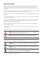

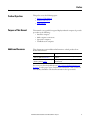
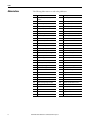

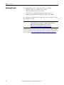
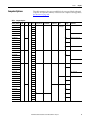
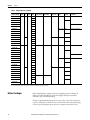
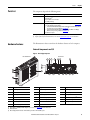


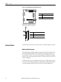
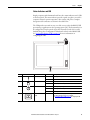


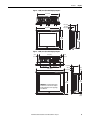
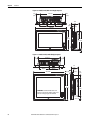

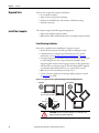


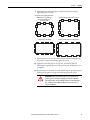
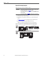

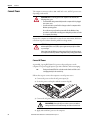
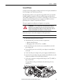

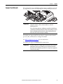

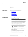

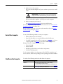


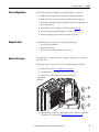
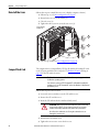
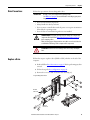
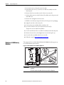


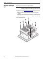
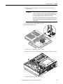

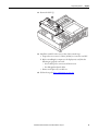

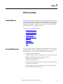
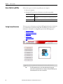
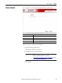
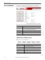

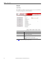
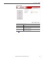

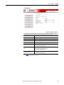
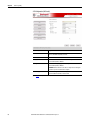
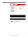

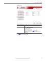

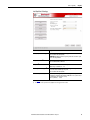
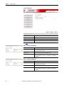
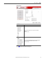
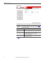

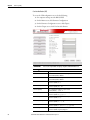


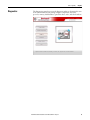

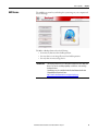
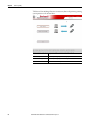


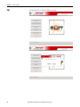

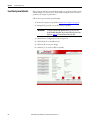
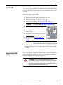
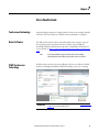
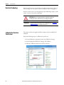
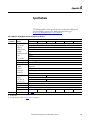

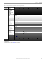
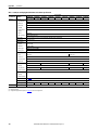
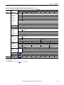

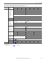

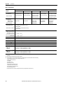

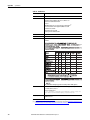
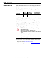

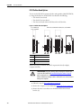
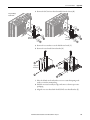
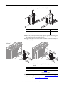


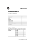
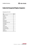
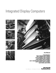

![[Insert the picture here]](http://vs1.manualzilla.com/store/data/005750886_1-61b7896b0a61bec1f004b64a994fc9d3-150x150.png)