1
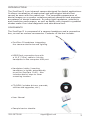
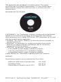
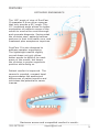
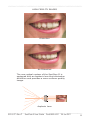
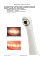
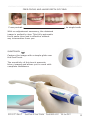
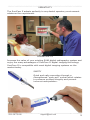
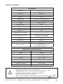
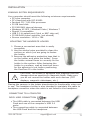
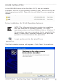
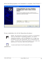
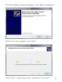
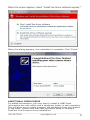
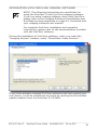
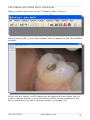
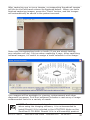
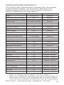
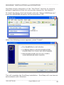
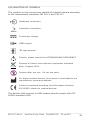
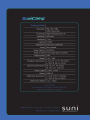
CONTENTS
PREFACE . . . . . . . . . . . . . . . . . . . . . . . . . . . . .2
INTRODUCTION . . . . . . . . . . . . . . . . . . . . . . . .3
FEATURES . . . . . . . . . . . . . . . . . . . . . . . . . . . .5
SPECIFICATIONS . . . . . . . . . . . . . . . . . . . . . . . 10
INSTALLATION . . . . . . . . . . . . . . . . . . . . . . . . . 1
1
INTEGRATION WITH PROF.SUNI . . . . . . . . . . . . .16
CAPTURING AN IMAGE WITH PROF.SUNI . . . . . . .21
SUNITOUCH
IMAGE CAPTURE . . . . . . . . . . . .23
IMAGING SOFTWARE COMPATIBILITY . . . . . . . . . 24
SUNISNAP INSTALLATION/OPERATION . . . . . . . . 25
SAFETY INSTRUCTIONS . . . . . . . . . . . . . . . . . . 29
REGULATORY REQUIREMENTS . . . . . . . . . . . . . .30
EXPLANATION OF SYMBOLS . . . . . . . . . . . . . . . .34
MAINTENANCE & CLEANING/DISINFECTING. . . . .35
TROUBLESHOOTING . . . . . . . . . . . . . . . . . . . . .36
FREQUENTLY ASKED QUESTIONS . . . . . . . . . . . .37
TECHNICAL SUPPORT/CUSTOMER SERVICE . . . . .39
LIMITED WARRANTY . . . . . . . . . . . . . . . . . . . . .40
PRODUCT REGISTRATION . . . . . . . . . . . . . . . . .41
SCLS-271 / SuniCam II User Manual
(with Prof.Suni integration)
PN#900-0631 - Rev. C
1/26/11
1.800.GET.SUNI
[email protected]
1
PREFACE
Thank you for purchasing the SuniCam II Intraoral Camera.
This User Manual will provide you with knowledge and resources
necessary in getting the most value from your SuniCam II Intraoral
Camera.
In order to optimize the use of the intraoral camera, while taking all
the necessary precautions, it is recommended to carefully read and
follow the user manual.
Always carefully consider the messages CAUTION, WARNING,
and NOTE symbols when using the manual. See page 34 for an
explanation of all symbols.
You may also benefit from the Suni Support Services web-based
resources, which include:
•
•
•
•
•
Regularly-updated Knowledge Base Articles
Downloadable Driver and Application Updates
Downloadable Product User Manuals and Reference Guides
Comprehensive List of Frequently Asked Questions
Technical Services and Support Contact Information
Please visit the support section at the Suni website at your
convenience: www.suni.com/support.
Information in this document is subject to change without notice.
Trademarks used in this document: Suni, the Suni logo and the
SuniCam II logo are trademarks of Suni Medical Imaging, Inc.;
Microsoft and Windows are registered trademarks of Microsoft
Corporation.
© 2011 Suni Medical Imaging, Inc., All rights reserved.
SCLS-271 Rev C
SuniCam II User Guide Part# 900-0631 26 Jan 2011
2
INTRODUCTION
The SuniCam II is an intraoral camera designed for dental applications.
It allows visualization of anatomical and pathological details that
cannot be seen with the naked eye. The immediate appearance of
dental images on a monitor enhances patient education and promotes
acceptance of dental treatment. Its extra-light handpiece, sensitivity
and resolution performance, as well as fidelity with respect to gradient
shades make it an ideal diagnostic and educational tool.
COMPONENTS
The SuniCam II is composed of a camera handpiece and a connection
box, as well as various accessories. Contents of the box include:
• SuniCam II handpiece integrating
the camera electronics and lighting
• USB2 Dock connection box with
a 11.5’ (3.5m) cable to link the
handpiece to the computer USB port
• Handpiece holder (inserting
handpiece in holder automatically
turns the SuniCam II off). Also
includes alcohol wipe to clean
mounting location.
• CD-ROM (includes drivers, manuals,
utilities and upgrades, etc.)
• User Manual
• Sample barrier sheaths
1.800.GET.SUNI
[email protected]
3
This equipment was packaged in a custom carton. The carton
should be kept for possible transportation. For more details about
these products, please visit www.suni.com, or contact your Suni
representative.
INCLUDED ON THE CD-ROM
• DOCUMENTS: The “Documents” directory contains all the documents
related to the SuniCam II including the all-important User Manual;
these documents are in Adobe PDF format. PDF documents can be read
with the Acrobat Reader application.
• DRIVERS: The “Drivers” directory contains the drivers necessary to
use the SuniCam II.
• SUNISNAP: An application for configuring keyboard and mouse
functions in imaging software applications that do not directly
support the SuniTouch button.
• UTILITIES: The directory “Utilities” contains:
• The ADOBE Acrobat Reader installation program.
• The Microsoft DirectX 9.0c installation program.
• DirectVideo Capture update installation program.
• SUNI PRODUCTS: Information regarding other Suni products.
SUPPLIES
The following supplies can be ordered from Suni Sales:
Additional USB2 Dock Connection Box
Handpiece Holder Camera Barrier Sheaths (box of 500)
SCLS-271 Rev C
400-1266
400-1273
900-0623
SuniCam II User Guide Part# 900-0631 26 Jan 2011
4
FEATURES
OPTIMIZED ERGONOMICS
The 105° angle of view of SuniCam
II separates it from other cameras
that only provide a 90° angle. This
15° increased angle allows for better
exploration of posterior areas of the
mouth to ensure the most thorough
and accurate diagnosis. Seeing what
the clinician sees, patients become
partners in their oral health care, and
treatment plan acceptance improves.
SuniCam II is also designed to
address operator ergonomics.
The lightweight wand’s slightly
curved shape not only allows
better access to difficult to reach
areas of the mouth, but keeps
the clinician in proper ergonomic
position while doing so.
Patient comfort is improved. The
camera’s rounded, compact head
accommodates the anatomical
differences of patient mouths and
minimizes the potential to cause
trauma.
Maximum access and unequalled comfort in mouth.
1.800.GET.SUNI
[email protected]
5
HIGH FIDELITY IMAGES
Distortion
No Distortion
The new optical system of the SuniCam II is
equipped with an aspheric lens that eliminates
distortion and provides a more uniform quality
image.
Aspheric Lens
SCLS-271 Rev C
SuniCam II User Guide Part# 900-0631 26 Jan 2011
6
UNMATCHED LIGHTING SYSTEM
The new SuniCam II lighting system is composed of the latest
generation 8-array LEDs which utilize condensers to focus the
light and produce a very powerful beam:
• Image is luminous in any circumstance
• Emitted heat is reduced
• Entire image is uniformly illuminated
(minimal shading)
Classic LEDs without condenser.
SuniCam II LEDs with condenser.
1.800.GET.SUNI
[email protected]
7
FREE-FOCUS AND LARGE DEPTH OF FIELD
From portrait
to single tooth
With no adjustment necessary, the obtained
image is perfectly clear. This fully-automatic
focus saves time and is effective without
any intervention from you.
SUNITOUCH
Capture the image with a simple glide over
the SuniTouch.
The sensitivity of this touch prevents
blurry images and allows you to work with
complete confidence.
SCLS-271 Rev C
SuniCam II User Guide Part# 900-0631 26 Jan 2011
8
VERSATILITY
The SuniCam II adapts perfectly to any dental operatory environment
whatever the requirement.
COMPATIBILITY
Increase the value of your existing SUNI digital radiography system and
enjoy the many advantages of SuniCam II digital imaging technology.
SuniCam II is compatible with most digital imaging systems on the
market today.
SAFETY
Quick and safe connection through a
strengthened “push-pull” socket which rotates
to preserve product integrity and prevent
incorrect manipulation.
1.800.GET.SUNI
[email protected]
9
SPECIFICATIONS
SuniCam II
Resolution
PAL 752 x 582
NTSC 768 x 494
Definition
470 lines
Technology
High-sensitivity CCD 1/4’’
Lighting
8 LEDs
Adjustment
Free focus (fully-automatic)
Depth of Field
From one tooth to portrait
Image
Non-inverted
Angle of View
78°
Angle of Vision
105°
Weight
2 oz. / 55g
Distortion
14%
Handpiece Dimensions
L: 8.1; W: 1.1; H: .95 inches
L: 205; W: 28; H: 24 mm
Distal Part Dimensions
W: .65 x H: .43 inches
W: 16.5 x H: 10.8 mm
Sensitivity
2 lux
LED Color T°
5200°K
LED Power
35,000 Lux
Image Capture
SuniTouch
USB2 Dock button actuation
Software actuation
USB2 Dock (Connecting Box)
Cable Length
11.5 ft. / 3.5 m
Output
USB 2.0
Dimension
L: 4; W: 1.8; H: .8 inches
L: 100; W: 46; H: 20mm
Weight
6 oz. / 165g
Operating Temperature
50°F to 104°F / 10°C to 40°C
Storage Temperature
4°F to 113°F / -20°C to 45°C
Relative Humidity
10% to 90%
Atmospheric Pressure
900 hPa to 1,060 hPa
• Continuous service.
• Not protected against water chutes (IPX0).
• Not adapted to the use in presence of an anaesthetic mixture
flammable with air, oxygen or dinitrogen monoxide.
• Complies with the European directive 93/42/EEC.
• Complies with EC60601-1 standard.
• Power is directly supplied through the computer USB port . The voltage
powering the camera is continuous 5V low voltage type
(0.5A).
SCLS-271 Rev C
SuniCam II User Guide Part# 900-0631 26 Jan 2011
10
INSTALLATION
MINIMUM SYSTEM REQUIREMENTS
Your computer should meet the following minimum requirements:
• PC-type computer
• PC complying with IEC 60950
• Pentium III – 500 MHz processor
• 20 GB hard disk
• 512 MB RAM internal storage
• Windows XP SP3 / Windows Vista / Windows 7
• DirectX 9 compatible
• USB 2.0 hi-speed port (Intel or NEC chip set)
• 32 MB RAM video controller (not shared)
• Screen resolution: 1024 x 768
MOUNTING THE HANDPIECE HOLDER
1. Choose a convenient area that is easily
accessible.
2. Use the alcohol wipe provided to clean the
surface on which you are going to fasten
the holder.
3. Remove the adhesive protection tape that is
on the holder, and place the holder. Press
the holder several times to correctly fix the
holder to the surface. After fastening the
holder to a surface, wait at least two hours
for the adhesive to set before positioning
the SuniCam II in the holder.
CAUTION: The holder is equipped with magnets that can
damage devices sensitive to magnetic fields. Make sure
you do not mount the holder near such devices (CRT
displays, magnetic videotapes, etc.).
Placing the camera in the holder deactivates its functionality when not
in use. The handpiece holder is also intended to maintain the cable to
handpiece connector when the cable is not linked to the handpiece.
CONNECTING TO A COMPUTER
DOCK USB2 CONNECTION
• The USB cable is connected between the USB
Dock and one of the computer’s USB 2.0
ports.
• The connecting cable is connected between
the USB Dock and the handpiece.
1.800.GET.SUNI
[email protected]
11
DRIVER INSTALLATION
In the DRIVERS folder of the SuniCam II CD, are two installer
programs: one for 32-bit operating systems (x86), and one for 64-bit
operating systems (x64). Open the correct folder for your operating
system.
Driver installation for 32-bit Operating Systems:
NOTE: The following instructions pertain to installation
with the Windows XP operating system. For other
operating systems, such as Windows Vista or Windows 7,
the procedure may vary somewhat, but is essentially the
same. Contact Suni Technical Support if you have any
questions or concerns about the procedure.
Locate and launch the file dpinst32.exe
The first installer screen will appear. Click ‘Next’ to continue.
SCLS-271 Rev C
SuniCam II User Guide Part# 900-0631 26 Jan 2011
12
When this dialog appears, the installation is complete. Click “Finish.”
Driver installation for 64-bit Operating Systems:
NOTE: The following instructions pertain to installation
with the Windows 7 operating system. For other
operating systems, such as Windows XP or Vista, the
procedure may vary somewhat, but is essentially the
same. Contact Suni Technical Support if you have any
questions or concerns about the procedure.
Locate and launch the file dpinst64.exe
1.800.GET.SUNI
[email protected]
13
The first installer screen will appear. Click ‘Next’ to continue.
When this screen appears, click “Next.”
SCLS-271 Rev C
SuniCam II User Guide Part# 900-0631 26 Jan 2011
14
When this screen appears, select “Install this driver software anyway.”
When this dialog appears, the installation is complete. Click “Finish.”
ADDITIONAL OPERATORIES
For added convenience, you may want to install a USB2 Dock
(connection box with cable) and a handpiece holder in each operatory.
This will allow you to easily transport the handpiece from one location
to the other. Please note that each operatory using or sharing a
SuniCam II will require driver installation.
1.800.GET.SUNI
[email protected]
15
INTEGRATION WITH PROF.SUNI IMAGING SOFTWARE
NOTE: The following instructions are specifically for
using the SuniCam II with Prof.Suni imaging software.
If you are using imaging software other than Prof.Suni,
please refer to the Imaging Software Compatibility and
SuniSnap sections beginning on page 24, combined with
your imaging software user manual.
For complete Prof.Suni installation and operation
instructions, please refer to the documentation included
with the Prof.Suni software.
During the installation of Prof.Suni software, when you reach the
“Imaging Devices” window, select “DirectVideo Video Devices”:
If you have alreadly installed Prof.Suni software and this module was
not chosen, it can be installed at any time by running the DirectVideo
update installer from the SuniCam II CD-ROM.
SCLS-271 Rev C
SuniCam II User Guide Part# 900-0631 26 Jan 2011
16
SUNICAM II CONFIGURATION
NOTE: These instructions explain how to change the
SuniCam II settings, and how to return the settings to
the default or other preferred settings. If the SuniCam II
is functional, the following steps may not be necessary.
Launch the Prof.Suni software, and you will see the screen below. In
the “Tools” menu, select “Imaging Device Extensions”:
You will see the “Image Device Extensions” window. For the SuniTouch
feature to function, the “DirectVideo Capture” version must be at least
version 2.0 (Build 18). If it is not, an update can be found at:
http://www.apteryxware.com/dental/downloads/xva3_5/xv-components.shtml,
or in the UTILITIES directory of the SuniCam II CD-ROM. Once you
have confirmed the correct version is installed, double-click “Direct
Video Capture”:
1.800.GET.SUNI
[email protected]
17
At this point you should have live video in the DirectVideo window.
If you use the SuniTouch button on the camera, it should capture an
image on the left side of the window:
If you click on Video Devices, you should see a check next to “1 USB
2820 Video”:
Click on “Video Options” and select “Video Capture”:
SCLS-271 Rev C
SuniCam II User Guide Part# 900-0631 26 Jan 2011
18
A “Properties” window will appear. Select the correct “Video Standard”
for your region (NTSC or PAL). Then, select the tab “Video Proc Amp”:
NOTE: SuniCam II cameras are available in both NTSC and
PAL formats, designated by the suffix of the SuniCam II
serial number; “-N” (for NTSC) or “-P” (for PAL).
These controls allow you to adjust several settings pertaining to the
image quality. Adjust as preferred and click “OK”:
1.800.GET.SUNI
[email protected]
19
You will return to the DirectVideo screen. Click on “Video Options”
and select “Video Capture Pin” under “Color Space/Compression,” the
setting should be “I420.” If not, adjust accordingly:
Click on “Video Options” and select “Video Crossbar.” The setting
should be “Video SVideo In.” If not, adjust accordingly:
Click “OK” to close the “DirectVideo” window. If all is correctly
configured, click “OK” on the “Imaging Device Extensions” window.
This will return you to the Prof.Suni main window.
SCLS-271 Rev C
SuniCam II User Guide Part# 900-0631 26 Jan 2011
20
CAPTURING AN IMAGE WITH PROF.SUNI
Open a patient and click on the “Capture Video” button:
After pressing OK, a live video stream should appear in the DirectVideo
window.
When you are ready, a still image can be captured from either the onscreen capture button or the SuniTouch button on the handpiece (for
more information on the SuniTouch button, see page 23).
1.800.GET.SUNI
[email protected]
21
After capturing one or more images, corresponding thumbnail images
will tile on the left-hand column as displayed below. When you have
finished capturing images, press the “Done” button, and the images
will automatically be saved in the patient account.
Select the corresponding tooth or teeth (if you are simply testing,
any selection will do). Just as when capturing X-rays, when capturing
intraoral images, it’s useful to assign a tooth selection to the image.
Your images will be available for viewing, enhancement and other
diagnostic purposes. Prof.Suni software includes a vast array of image
enhancement tools for a variety of needs.
NOTE: To obtain potential performance improvement
when using the imaging software, it is recommended to
install DirectX 9.0c included in the UTILITIES folder on the
SuniCam II CD-ROM. DirectX 9.0c is a Microsoft® product.
SCLS-271 Rev C
SuniCam II User Guide Part# 900-0631 26 Jan 2011
22
SUNITOUCH
IMAGE CAPTURE
Motion blur is a common problem in other cameras, caused by
pressing a mechanical button. The SuniTouch is a unique feature in
that you only need to lightly glide your finger across the surface to
capture an image, greatly reducing the potential for blurry images.
• The SuniCam II will automatically power on when you proceed to
capture an image in Prof.Suni. • To capture an image, lightly glide your
finger across SuniTouch as soon as the
desired image appears on the monitor.
The image is automatically captured
and displayed on the screen.
• Each finger glide across SuniTouch will
capture another image.
NOTE: If the SuniTouch feature does not function,
please refer to the DRIVER REINSTALLATION procedure
in the TROUBLESHOOTING section of this manual.
1.800.GET.SUNI
[email protected]
23
IMAGING SOFTWARE COMPATIBILITY
The following matrix indicates feature integration with various dental
imaging software products. Use this guide to determine if your
software supports the SuniTouch feature, requires SuniSnap, or
employs a TWAIN driver for image capture:
Imaging Software
Adstra
AFP Imaging (Dent-X ProImage)
Version
Image Capture
v5.1, 6.2, 7.0
SuniTouch
v6.14
SuniTouch
Apteryx XrayVision
v3.7, build 12 or above
SuniTouch
Apteryx XVLite
v2.0, build 25 or above
SuniTouch
CliniViewXV
n/a
SuniTouch
Dentimax
n/a
SuniTouch
Dentrix G2 w/Image
v4.5
SuniTouch
v7.0, 8.0
SuniTouch
v10.5
SuniTouch
3.4
SuniTouch
EasyDental EasyImage Four5
n/a
SuniTouch
Gendex Vixwin Platinum/Pro
v1.5 (with patch)
SuniTouch
v5+
SuniTouch
NGP Logos
5.34
SuniTouch
Patient Gallery (Image FX)
v1.52
SuniTouch
v13+, V14+
SuniTouch
PEB/XLDent with ImageXL
n/a
SuniTouch
Soredex Digora
2.5
SuniTouch
CADI Imaging
n/a
SuniSnap / SuniTouch
ChairSide Dental
Dexis
Dolphin Imaging
Durr DBSWin
Mediadent
Patterson EagleSoft Imaging
v5.1
SuniSnap / SuniTouch
CompuDent
Z1
SuniSnap / SuniTouch
DampSoft
n/a
SuniSnap / SuniTouch
Kodak Dental Imaging
v6.7
SuniSnap / SuniTouch
Kodak Practice Works
v6.0, v7.0
SuniSnap / SuniTouch
Kodak Softdent
v11.0
SuniSnap / SuniTouch
Owandy Julie
v3.14
SuniSnap / SuniTouch
PLANMECA Dimaxis Imaging
n/a
SuniSnap / SuniTouch
Schick CDR DICOM
v3.5
SuniSnap / SuniTouch
Sirona Sidexis
XG
SuniSnap / SuniTouch
Tigerview *
n/a
SuniSnap / SuniTouch
MOGO Practice Management **
n/a
Twain Only
*
Tigerview provides all technical support for software integration and
usage. For Tigerview support, call (800) 385-9593 - Option 2.
** When using a TWAIN driver with MOGO, you can only preview images in a
small window; the large view will be available after the image is captured.
You will also have to reacquire the TWAIN driver after each image capture.
SCLS-271 Rev C
SuniCam II User Guide Part# 900-0631 26 Jan 2011
24
SUNISNAP INSTALLATION and OPERATION
SuniSnap allows integration of the “SuniTouch” function to imaging
software applications that do not provide support for this feature.
To install SuniSnap, find and double-click the “Setup SUNISnap.exe”
from the SUNISNAP directory of the SuniCam II CD:
When the following screen appears, press “Install”:
This will complete the SuniSnap installation. SuniSnap will now launch
automatically with Windows.
1.800.GET.SUNI
[email protected]
25
USING SUNISNAP
• After installation, the SuniSnap icon will be displayed on
the screen. The icon will remain in the foreground and
it is possible to move it around the screen as needed.
The last position is memorized each time you restart the
computer.
• If you wish to mask SuniSnap, simply click on the
SuniSnap title bar and press the “Escape” key on the
keyboard.
• If you wish to exit SuniSnap, simply click on the
word “Snap” (the title bar) and press “Alt+F4” on the
keyboard.
• To capture an image, click on the “Snap” button (on your
screen) or press the SuniTouch on the camera.
CUSTOMIZING SUNISNAP
To access the “Settings” panel, hold down the “Ctrl” key on the
keyboard, and click the SuniSnap icon:
SCLS-271 Rev C
SuniCam II User Guide Part# 900-0631 26 Jan 2011
26
Video source: When properly installed, this window will list
the video source as “USB 2820 Video.”
Action type: You can define up to three different actions.
These actions will be executed in numerical
order whenever the SuniTouch is activated.
External application: This is typically defined as the imaging
application.
Function: For each action, it is possible to specify
different behaviors according to the external
application chosen.
Parameters: Functions like “Send WM_COMMAND” and
“Send Message” will need specific input that
will appear in this area.
Return to live: After an image capture, this check box will
specify if the camera switches back to live.
1.800.GET.SUNI
[email protected]
27
HOW TO SELECT THE VIDEO INPUT:
Choose “USB 2820 Video” as video source.
HOW TO CHOOSE AN ACTION:
Among the three possible actions, choose the one which will be set up
(typically Action #1).
HOW TO CHOOSE THE EXTERNAL APPLICATION:
To choose the external application, click on the circle icon to the right of
the “External application” field and hold the mouse button down.
The settings window will disappear, giving you full access to the screen.
Place the mouse cursor on the command (“CAPTURE” for example) or
window that manages video acquisition in the imaging application. If the
imaging application command or window has a title or name, this name
will be displayed in the “External application” box.
You may then select the action required to activate SuniTouch (such as
“Button Click” or “Button double click”). This may be a button click, a
double click, a message or command sent, a joystick button movement
or a mouse click anywhere on the screen. For instance, a “mouse click.”
If the name displayed in the imaging application title bar is totally
different from all of the other applications you use, and as long as it is
not modified during the work sessions, you may select the “Search title
text” box if SuniSnap does not function correctly.
If you only need one action, click the “OK” button. Otherwise, select the
next action and do the same steps as before.
ADVANCED CONFIGURATION
Depending on the imaging software used and your familiarity with it,
you may need to use the “Send message” Action. In this case, three
further parameters will be displayed:
• The message number
• WParam value
• LParam value
When using the “Send WM_COMMAND” Action, you must only enter
the WParam and LParam values. To obtain these values, you need
to be very familiar with the target imaging software or you will need
editor information and some tools to help you understand the software
interface.
NOTE: With some imaging systems, the SuniCam II may
require two touches to capture and save an image. The
first touch captures the image, the second touch returns
to live streaming video.
SCLS-271 Rev C
SuniCam II User Guide Part# 900-0631 26 Jan 2011
28
SAFETY INSTRUCTIONS
• Do not expose the dental camera to water spray and do
not store it in a humid environment (electrocution risk).
• Install the dental camera in a clean, dry, and wellventilated area.
• Disconnect the camera from the power supply if you
are not going to use it for several days. Do not pull on
the cable.
• Never compress or nip the handpiece cable.
• Never expose the product to high vibrations.
• Do not drop the camera.
• This camera should never be immersed in any liquid,
nor should it be autoclaved.
• The surface temperature in the light emission area can
be just above 41°C (after several minutes of use). So,
avoid maintaining this emission area in contact with the
patient’s mouth.
• The SuniCam II camera is a product using class II LEDs
according to IEC 60825. Do not stare at them in order
to avoid any ocular risk.
• For each new patient, it is essential to use the
barrier sheaths provided with the camera or as a
complement. For best results use Suni brand sheaths;
additional barriers can be purchased from your Suni
representative or by calling Suni at 1.800.GET.SUNI.
• Before using the camera, make sure it does not have
any sharp edges.
NOTE: If the barrier sheath is torn while examining
a patient or if the handpiece was contaminated while
withdrawing the barrier sheath, it is essential to totally
disinfect the handpiece. In order to do this, refer to the
“Maintenance & Cleaning/Disinfecting” section of this
manual.
1.800.GET.SUNI
[email protected]
29
REGULATORY REQUIREMENTS
COMPLIANCE WITH STANDARDS AND REGULATIONS
This product was designed and manufactured by a company having an
authorized quality system. It meets the requirements of the European directive
93/42/EEC, relative to medical devices. Therefore, it particularly meets
electrical safety and electromagnetic compatibility standards (IEC) (CEM).
ELECTROMAGNETIC INTERFERENCE AND ELECTROSTATIC DISCHARGES
Electromagnetic compatibility (CEM) is the ability of electronic device elements
to correctly interact in an electronic environment. Although this dental camera
system was designed according to this compatibility and complies with the
electromagnetic interference thresholds established by the regulatory agency,
there is no guarantee about the interference likely to occur on a particular
installation.
If the device generates interference with radio communication services (which
can be determined by switching it off and on), the user is recommended to try
to correct this phenomenon by taking whole or part of the following measures:
• Change the receiving antenna orientation.
• Reposition the product according to the receiver.
• Take away the computer from the receiver.
The SuniCam II dental camera system is designed and tested to be used in a
home environment, class B Group 1, according to CISPR11 standard.
MEDICAL DEVICE VIGILANCE
The intraoral dental camera is considered a medical device, which is subjected
to the medical device vigilance dispositions; any serious dysfunction should
then be the subject of a description to the competent authorities and to the
manufacturer as soon as possible and as precisely as possible.
END OF LIFE
This device bears the recycling symbol according to the European directive
2002/96/EC about electric and electronic equipment waste (DEEE or WEEE).
Properly disposing of this device will contribute to avoiding any damage done to
the environment or human health.
This symbol present on the device or on the accompanying
documentation indicates this product cannot be in any way treated
as household waste. Therefore, it should be given to a waste
collection agency in charge of electric and electronic equipment
recycling.
For more details relative to scrapping, recuperation and recycling,
of device, contact Suni. In addition, check with the appropriate
local, state or country offices for instructions specific to your area.
Always respect the standards and regulations in force in your area.
SCLS-271 Rev C
SuniCam II User Guide Part# 900-0631 26 Jan 2011
30
ELECTROMAGNETIC COMPATIBILITY
Guide and declaration of the manufacturer - electromagnetic emissions
The SuniCam II device is intended to be used in the electromagnetic environment
specified below. The user should make sure it is used in this environment.
Emission Trial
Compliance
Electromatic Environment Guide
RF emissions
CISPR 11
Group 1
The SuniCam II only uses radio energy for its
internal functions. Therefore, its RF emissions
are very low and are not likely to cause
interference with near electronic devices.
RF emissions
CISPR 11
Class B
Harmonic emissions
EN 61000-3-2
Not applicable
The SuniCam II may be used in domestic
premises, including the ones directly
connected to the public low voltage power
distribution network used to supply household
buildings.
Voltage fluctuations /
Flicker
EN 61000-3-3
Not applicable
Guide and declaration of the manufacturer - electromagnetic immunity
The SuniCam II device is intended to be used in the electromagnetic environment
specified below. The user should make sure it is used in this environment.
Immunity Trial
CEI 60601
Severity Level
Compliance
Level
Electromagnetic Environment
Guide
The floor should be wooden,
concrete or tile. If the floor
is covered with a synthetic
material, the relative humidity
should be at least 30%.
Electrostatic
discharges
EN 61000-4-2
± 6 kV when in
contact
± 8 kV in the air
± 6 kV
Far transient
bursts
EN 61000-4-4
± 2 kV for the
feed cables
± 1 kV for the
input/output
cables
± 2 kV
Voltage shocks
EN 61000-4-5
Differential mode
± 1 kV
Common mode
± 2 kV
± 1 kV
N.A.
The main power supply quality
should be one of a traditional
commercial or hospital
environment.
Dips, brief
outages and
power voltage
variation
EN 61000-4-11
• <5% U T
for 10 ms
• 40% U T
for 100 ms
• 70% U T
for 500 ms
• <5% U T
for 5 s
<5% U
T
10 ms
<40% U
T
100 ms
<70% U
T
500 ms
<5% U
T
5s
The main power supply quality
should be one of a traditional
commercial or hospital
environment. If the user of the
SuniCam II device requires it
to continue to operate during
main power supply outages, it
is recommended the SuniCam II
device is fed by an inverter or a
battery.
Magnetic field
with the network
frequency
(50/60 Hz)
3 A/m
3 A/m
The magnetic field with the
network frequency should be at
a characteristic level of a location
in a traditional commercial or
hospital environment.
± 8 kV
± 1 kV
The main power supply quality
should be one of a traditional
commercial or hospital
environment.
Note: U
T is the power voltage nominal value applied during the trial.
1.800.GET.SUNI
[email protected]
31
Guide and declaration of the manufacturer - electromagnetic immunity
The SuniCam II is intended to be used in the electromagnetic environment specified
below. The user should make sure it is used in this environment.
Immunity
Trial
CEI 60601
Severity Level
Compliance
Level
Electromagnetic Environment
Guide
Portable and mobile RF
communication devices should not
be used at a distance from the
SuniCam II (including the cables),
lower than the recommended
separation distance, calculated with
the applicable formulas depending
on the emitter frequency.
Recommended separation distance
Conducted RF
EN 61000-4-6
3 Vrms
150 kHz
to 80 MHz
3V
Radiated RF
3 V/m
3V/m
EN 61000-4-3
80 MHz to 2.5
GHz
d = 1,16kMP
d = 1,16kMP 80 MHz to 800 MHz
d = 2,33kMP 800 MHz to 2.5 GHz
where P is the maximum rated
output of the transmitter in
watts (W) by the transmitter
manufacturer and d the
recommended separation distance
in meters (m).
The field levels emitted by the fixed
RF transmitters, determined by an
electromagnetic measurement of
the sitea, should be lower than the
compliance level in each frequency
band.
Interference may occur in the
vicinity of the devices bearing the
following symbol:
Note 1: At 80 MHz and 800 MHz, the higher frequency band applies.
Note 2: These recommendations may not apply in every situation. Electromagnetic wave
propagation is modified by the absorption and reflection due to the structures,
objects and persons.
a The fixed transmitter field levels, such as the base stations of the radio telephones
(cellular/wireless) and the terrestrial mobile radios, amateur radio, AM, FM, and
TV radio communication cannot be theoretically assessed precisely. To obtain the
electromagnetic environment due to the fixed RF transmitters, a site measurement
should be performed. If a field level measured in the use environment of the SuniCam
II exceeds the compliance levels above applicable, the good operation of the SuniCam
II should be checked. If abnormal operations are proved, some further measures
should be taken, such as reorientation or relocation of the standard device.
b Above the 150 kHz to 80 MHz frequency band, the field level should be lower than 3
V/m.
SCLS-271 Rev C
SuniCam II User Guide Part# 900-0631 26 Jan 2011
32
Recommended separation distances between the portable and mobile RF communication
devices and The SuniCam II
The SuniCam II is intended to be used in an electromagnetic environment in which
the irradiated RF disturbances are checked. The user of SuniCam II can help to avoid
electromagnetic interference by maintaining a minimal distance between the portable
and mobile RF communication devices (transmitters) and the recommended the
SuniCam II such as recommended below, depending on the maximal output power of
the communication device.
Rated maximal
output
power of the
transmitter
W
Separation distance depending on
the transmitter frequency
m
150 kHz to 80 MHz
80 MHz to 800 MHz
800 MHz to 2,5 GHz
d = 1,16kMP
d = 1,16kMP
d = 2,33kMP
0.01
0.116
0.116
0.233
0.1
0.366
0.366
0.736
1
1.16
1.16
2.33
10
3.66
3.66
7.36
100
11.6
11.6
23.3
For the transmitters whose maximal output is not listed above, the recommended
separation distance d in meters (m) can be determined by using the equation applicable
to the transmitter frequency, where P is the maximal output of the transmitter in watts
(W) rated by the transmitter manufacturer.
Note 1: At 80 MHz and at 800 MHz, the separation distance given in the higher
frequency band applies.
Note 2: These recommendations may not apply in every situation. The electromagnetic
wave propagation is modified by absorption and reflection due to the structures, objects
and persons.
1.800.GET.SUNI
[email protected]
33
EXPLANATION OF SYMBOLS
The symbols on the camera box identify the dental camera according
to the international standards CEI 601-1 and CEI 417.
Handpiece connection.
Footswitch connection.
Continuous voltage.
USB2 output.
“BF type camera.”
Caution, please consult the ACCOMPANYING DOCUMENTS.
Disposal of electric and electronic equipment marketed
after 1 August 2005.
Dispose after one use. Do not use twice.
For active medical devices, this symbol is associated to the
manufacturer name and address.
Product compliance according to the European directive
93/42/EEC relative to medical devices.
The devices that connect to USB outputs should comply with IEC
60950 standard 0459.
SCLS-271 Rev C
SuniCam II User Guide Part# 900-0631 26 Jan 2011
34
MAINTENANCE & CLEANING/DISINFECTING
For each new patient, it is essential to use the recommended camera
barrier sheaths. Barrier sheaths can be purchased from Suni.
Before first using the camera, it is imperative to follow the complete
disinfecting procedure.
Any device returning from service or maintenance should follow
the complete disinfecting procedure before being used. Likewise,
any device shipped to Suni for service or maintenance should be
disinfected prior to shipping.
WARNING: Do not directly spray disinfecting products on
the SuniCam II.
Do not use products containing:
• Ammoniac, trichloroethylene
• Dichloroethylene
• Ammonium hydrochloride
• Chlorinated and aromatic hydrocarbon
• Ethylene dichloride
• Methylene chloride
• Ketones
Use of these chemicals can cause deterioration of the plastic
parts.
DISINFECTANT RECOMMENDATIONS:
• Use of surface cleaning and disinfecting wipes.
• We recommend CaviWipes (manufactured by Metrex) or other
cleaning and disinfecting wipes with exact same chemistry.
INSTRUCTIONS:
• Take the cleaning and disinfecting wipe, wring it, and then scrub
the equipment until obtaining visible cleanliness.
• Allow device to dry in the open air.
PRECAUTIONS:
• Do not rinse or immerse device.
• Do not immerse device in a disinfecting liquid.
IN CASE OF CONTACT WITH BLOOD, SALIVA, SPATTER OR OTHER
IMPORTANT SOILING:
• It is strongly recommended to follow a disinfecting process.
• Clean the device with disinfecting wipes.
• Roll up several disinfecting wipes around the handpiece and leave
on for 15 minutes.
1.800.GET.SUNI
[email protected]
35
TROUBLESHOOTING
PROBLEMS
CAUSES
No image
displays on the
screen and the
camera LEDs
are not on.
• Connection
problem
The camera
switches on,
but no image
displays on the
screen.
• Configuration
• Driver
• Connection
problem
SOLUTIONS
Check that the connecting cable is
correctly connected to the handpiece
and to the connection box.
1. Check that the camera is correctly
set up in the imaging software (please
refer to the software user guide).
2. Check that the camera is correctly
detected in the device driver (correct
installation of its driver).
3. Check that the USB cable coming
from the DOCK (connection box) is
correctly connected to the computer’s
USB 2.0 port. Check the camera
configuration in the imaging software
(brightness, contrast, saturation, etc.).
An image
displays on the
screen, but the
quality is not
satisfactory.
• Camera driver
configuration
Check the camera configuration in
the Prof.Suni program (brightness,
contrast, saturation, etc.). Refer to
pages 17-20 of this manual.
An image
displays, but it
is not very clear
(blurry).
• Barrier sheath
Check that the barrier sheath is
correctly positioned on the camera
head. It is advisable to use SuniCam II
barrier sheaths, which are designed to
fit the camera properly.
If the problem persists, contact Suni Technical Support or your local
Suni distributor. If you are issued a Return Authorization (RMA), be
sure to pack the SuniCam II and all of its components (connection
box, handpiece, cables) in its original packaging. Refer to the LIMITED
WARRANTY for details. Do not return any products without first
receiving a return authorization. Please disinfect the camera before
returning it to Suni; disinfection procedures are located on previous
page.
SCLS-271 Rev C
SuniCam II User Guide Part# 900-0631 26 Jan 2011
36
FREQUENTLY ASKED QUESTIONS
Q: Where do I find the SuniCam II drivers?
A: The drivers can be found on the SuniCam II CD. Alternately, the
drivers are available at the support website: www.suni.com/support
Q: I have a grainy image, and it seems to be slightly green as well.
Why?
A: This problem can arise when The SuniCam II connection box
is plugged into a USB 1.1 port. Make sure that the SuniCam II is
connected to a USB 2.0 port. Inexpensive hardware upgrades are
readily available for computers with USB 1.1 only ports.
Q: I have a grainy image, and it seems to be slightly green as well. I
already checked, and my computer has USB 2.0 ports. What do I do
now?
A: Although USB 2.0 ports provide the required data transmission
speed, it is sometimes possible that the USB 2.0 port does not provide
adequate power to support all of the USB devices connected to the
computer. In particular, devices such as USB printers and scanners
can create an overall demand for additional USB power. If this is the
case, we recommend the purchase of a powered USB 2.0 hub, which
may resolve the problem by providing supplemental power to the
system.
Be sure you have a powered or “active” USB 2.0 hub. Sometimes a
computer is unable to supply adequate power to the USB port used by
our docks, particularly if there may be other devices utilizing too much
power on the USB bus. Other devices can include printers, cameras, or
even a USB mouse and keyboard.
Q: I have no image at all. I have never before had an image through
this USB port.
A: Install or reinstall the driver set. If you already have installed the
drivers properly, and if the device is listed as “USB 2820 Video” in the
Device Manager, then make sure to change the configuration input
from “Video Composite In” to “Video S - Video IN.”
Q: The image displayed is very small and/or loses detail when resized.
A: Confirm that you are using a USB 2.0 port and that any means of
extension (USB hub, USB extender hardware, video capture device,
etc.) supports USB 2.0. Many of these devices do not support the
USB 2.0 specification, and as such, can only render a 320x240 video
stream.
1.800.GET.SUNI
[email protected]
37
Q: My camera displays a video stream but the SuniTouch button no
longer functions.
A: Verify that the “Driver Provider” is identified as “Sopro” and not
eMPIA Technology. This can be determined by checking the entry
under Device Manager. The Windows Update service from Microsoft will
potentially replace the driver set from Sopro with an incorrect version
from eMPIA, which will disable the SuniTouch capture function.
Q: The image is very jumpy and not clear. Is there something wrong
with my camera?
A: Refer to the CONFIGURATION procedure in the INTEGRATION
section of this user manual:
• From the Prof.Suni “Tools” menu, choose “Imaging Device
Extensions.”
• In the window that opens, double-click “DirectVideo Capture.”
• Choose the Video Options” tab, and select “Video Capture Pin.”
• Go to the “Video” tab, and click “Capture Pin.”
• Change the “Color space/Compression” from “YUY2” to “I420.”
Q: When I plug my docking station into the USB port, I get a message
saying, “One of the Devices on this computer has malfunctioned, and
Windows does not recognize it.” Why?
A: Your computer is unable to properly supply adequate power to the
docking station’s USB connection. We recommend the purchase of a
powered USB 2.0 hub.
Q: I moved the camera to a different USB port and now the camera
does not work.
A: It sometimes becomes necessary to reinstall the drivers simply by
plugging a USB device into a different port. You may consider trying
different ports until the device becomes recognized, or simply reinstall
the drivers. Under the Device Manager, you may see the device listed
as USB 2820 Video #2, #3, etc., depending on the number of times the
drivers have been installed on different USB ports.
Q: Yesterday my camera was working fine. Today I have no image.
What happened?
A: Confirm that the USB 2820 Video is listed in the device manager
(refer to the previous answer). Also, confirm that camera input is
configured as “S-Video,” and not “Composite.”
SCLS-271 Rev C
SuniCam II User Guide Part# 900-0631 26 Jan 2011
38
TECHNICAL SUPPORT AND CUSTOMER SERVICE
Suni is committed to providing comprehensive technical support and
customer service for all Suni systems. We encourage users to contact
us with questions, or to obtain technical information regarding the
performance of Suni products.
1.800.GETSUNI / 1.800.438.7864
In addition to providing phone-based technical support, Suni offers
high-priority e-mail support, in which we strive to answer your
questions quickly, via e-mail. Please contact us at: [email protected]
Additionally, Suni offers technical support from the Suni website.
Users will find useful information regarding the performance of Suni
products, frequently-asked questions, application updates, and more:
www.suni.com/support
1.800.GETSUNI / 1.800.438.7864
[email protected]
www.suni.com
Suni Medical Imaging, Inc.
6840 Via Del Oro
San Jose, Ca 95119
Unites States of America
Manufactured for
Suni Medical Imaging, Inc.
6840 Via Del Oro
San Jose, Ca 95119
Unites States of America
1.800.GET.SUNI
[email protected]
39
LIMITED WARRANTY
(1) Suni Medical Imaging, Inc. warrants to the original purchaser that the SUNICAM II Intraoral Camera
(the “Product”) will be free from material defects in material and workmanship for a period of 12 months
from the date of original purchase from Suni Medical Imaging, Inc. or its authorized distributor (the
“Warranty Period”). During the Warranty Period, Suni Medical Imaging, Inc. will repair Product not
meeting the foregoing Limited Warranty (or at its option, replace such Product with a new or reconditioned
Product) at no charge. Any replacement or repaired Product will be warranted for the remainder of the
original Warranty Period. All Products or parts replaced become Suni Medical Imaging, Inc.’s property.
If neither repair or replacement is reasonably available, Suni Medical Imaging, Inc. may elect instead,
at its option, to accept return of the Product and refund the purchase price of the Product. This Limited
Warranty only covers the hardware components of this Product. This Limited Warranty does not cover, and
Suni Medical Imaging, Inc. is not responsible for, any software that may be used with this Product. This
Limited Warranty extends only to the original purchaser and is not transferable to anyone else. To ensure
warranty protection, complete the product registration form located on the following page and mail or fax
a copy along with a copy of the bill of sale to Suni.
(2) To obtain warranty service you must: (a) obtain a return materials authorization number (RMA#) from
Suni Medical Imaging, Inc., and (b) deliver the Product, in accordance with the instructions provided by
Suni Medical Imaging, Inc., along with proof of purchase in the form of a copy of the bill of sale including
the Product’s serial number, contact information, RMA# and detailed description of the defect, freight
prepaid, in either its original package or packaging providing the Product with a degree of protection
equivalent to that of the original packaging to the distributor whom you purchased the Product from or
if purchased from the factory to Suni Medical Imaging, Inc. Suni Medical Imaging, Inc. is not responsible
for any damage to the Product during transportation. Be sure to remove all parts, options, holders and
attachments prior to delivering the Product. Suni Medical Imaging, Inc. is not liable for any loss or damage
to such items.
(3) This Limited Warranty does not cover any consumables (such as barriers) supplied with this Product,
cosmetic damage, damage due to (a) acts of God, accident, misuse, abuse, negligence, abnormal or
unusually heavy use, causes external to the Product such as but not limited to excessive heat or humidity,
or modifications to this Product, (b) improper installation, operation, testing, or maintenance of this
Product, (c) power failure or connections to improper voltage supply, or (d) attempted repair by any party
other than Suni Medical Imaging, Inc. This Limited Warranty does not apply when malfunction results
from the use of the Product in conjunction with accessories, products or ancillary or peripheral equipment
not provided by Suni Medical Imaging, Inc., or where it is determined by Suni Medical Imaging, Inc.
that the Product itself complies with the Limited Warranty. This Limited Warranty does not apply if the
Product: is damaged by Electrostatic Discharges (ESD); is damaged as a result of autoclaving the camera;
is immersed in any liquid such as disinfectants, alcohol or any other liquid; sustains damage to internal
components; is damaged as a result of shock impact (such as dropping the Product); or is damaged as a
result of clamping the Product with hemostats or other utensils that deform, dent or damage the camera
enclosure. This Limited Warranty is invalid if the Product is used for purposes other than the use intended
by Suni Medical Imaging, Inc. This Limited Warranty is invalid if the factory-applied serial number has
been defaced, altered, obliterated or removed from the Product.
(4) Suni Medical Imaging, Inc. shall not be liable under this Limited Warranty if Suni Medical Imaging, Inc.
(a) cannot reproduce the alleged defect in its testing and examination of the Product or (b) discovers that
the Product is excluded from coverage under this Limited Warranty for any reason.
(5) Repair, replacement or return/refund as provided under this Limited Warranty is the sole and exclusive
remedy of the customer for any breach thereof.
(6) TO THE FULL EXTENT ALLOWED BY LAW, THE FOREGOING LIMITED WARRANTIES AND REMEDIES
ARE EXCLUSIVE AND ARE IN LIEU OF ALL OTHER WARRANTIES, TERMS, OR CONDITIONS, EXPRESS
OR IMPLIED, EITHER IN FACT OR BY OPERATION OF LAW, STATUTORY OR OTHERWISE, INCLUDING
WARRANTIES, TERMS, OR CONDITIONS OF MERCHANTABILITY, FITNESS FOR A PARTICULAR PURPOSE,
SATISFACTORY QUALITY, CORRESPONDENCE WITH DESCRIPTION, AND NON-INFRINGEMENT, ALL
OF WHICH ARE EXPRESSLY DISCLAIMED. SUNI MEDICAL IMAGING, INC. NEITHER ASSUMES NOR
AUTHORIZES ANY OTHER PERSON TO ASSUME FOR IT ANY OTHER LIABILITY IN CONNECTION WITH THE
SALE, INSTALLATION, MAINTENANCE OR USE OF ITS PRODUCTS.
(7) TO THE FULL EXTENT ALLOWED BY LAW, SUNI MEDICAL IMAGING, INC. ALSO EXCLUDES FOR
ITSELF AND ITS SUPPLIERS ANY LIABILITY, WHETHER BASED IN CONTRACT OR TORT (INCLUDING
NEGLIGENCE), FOR INCIDENTAL, CONSEQUENTIAL, INDIRECT, SPECIAL, OR PUNITIVE DAMAGES OF ANY
KIND, OR FOR LOSS OF REVENUE OR PROFITS, LOSS OF BUSINESS, LOSS OF INFORMATION OR DATA,
LOSS OF USE OF PRODUCT, OR OTHER FINANCIAL LOSS ARISING OUT OF OR IN CONNECTION WITH
THE SALE, INSTALLATION, MAINTENANCE, USE, PERFORMANCE, FAILURE, OR INTERRUPTION OF THIS
PRODUCT, EVEN IF ADVISED OF THE POSSIBILITY OF SUCH DAMAGES, AND LIMITS ITS LIABILITY TO
REPLACEMENT, REPAIR, OR REFUND OF THE PURCHASE PRICE PAID FOR THE PRODUCT BY CUSTOMER,
AT SUNI MEDICAL IMAGING, INC.’S OPTION. THIS DISCLAIMER OF LIABILITY FOR DAMAGES WILL NOT
BE AFFECTED IF ANY REMEDY PROVIDED HEREIN SHALL FAIL OF ITS ESSENTIAL PURPOSE. Any implied
warranty which cannot be disclaimed shall be limited in duration to the minimum duration required by
applicable law or the Warranty Period, whichever is greater. This Limited Warranty gives you specific legal
rights and you may have other rights, which vary, from jurisdiction to jurisdiction. Some jurisdictions do
not allow the exclusion or limitations of special, incidental or consequential damages or limitations on how
long a warranty lasts, so the above exclusion and limitation may not apply to you.
(8) This Limited Warranty shall be governed by the laws of the State of California, U.S.A. excluding its
conflicts of laws principles and excluding the United Nations Convention on Contracts for the International
Sale of Goods.
SCLS-271 Rev C
SuniCam II User Guide Part# 900-0631 26 Jan 2011
40
PRODUCT REGISTRATION FORM
Suni Medical Imaging, Inc.
6840 Via Del Oro
San Jose, CA 95119 USA
Local: 1.408.227.6698
Toll-free: 1.800.438.7864
Fax: 1.408.227.9949
www.suni.com
Date Purchased: ________________________________
Serial (s)#: ________________________________
________________________________
________________________________
Name: ________________________________
Address: ________________________________
City: ________________________________
State: ______
1.800.GET.SUNI
Zip Code: ________________
[email protected]
41