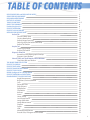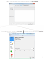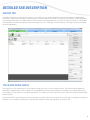
1
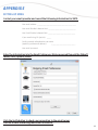
PN 0000062022
1
Revision
Effective Date
Description
1.0
September 1, 2010
Initial Draft
2.0,2.1,2.2
Not Applicable
These revisions not released.
2.3
February 15, 2012
Update to Version 2.3
Added description of feature and GUI changes
Added regulatory information
3.0
October 15, 2012
Update to Version 3.0
Revised feature and GUI changes
Revised regulatory information
3.2
May 1, 2013
Eliminated CE reference
Included EVA Select
3.3
May 1, 2014
Updated Company name
Updated GUI graphics
Added EVA, EVA Select Supplemental Information
Remove Durability Section
3.3.1
August 1, 2014
Update Address
3.4
March 31, 2015
Update to version 3.4 software
Update Email, Explain Study/History Modes
Eliminated EVA Classic Supplementary Information Appendix
Copyright notice
Copyright©2015 SMK Imaging LLC dba: ImageWorks. All
Rights Reserved. This manual shall not, wholly or in part,
in any form or by any means be reproduced or transmitted
without prior written authorization from ImageWorks.
This manual has been produced to assist in providing
instruction for EVAsoft and EVA digital sensor products.
Every effort has been made to make the information in
this guide as accurate as possible. The authors of this
guide shall have neither liability nor responsibility to any
person or entity with respect to any loss or damages in
connection with or arising from the information contained
in this manual.
Trademarks
EVA, Dent-X, and ImageWorks are registered trademarks of
SMK Imaging LLC. Any additional software products named
in this document are claimed as trademarks or registered
trademarks of their respective companies.
Regulatory Notes
ImageWorks provides you with the following information
regarding the regulatory status of EVAsoft, EVA, and EVA
Select:
United States of America
EVAsoft Digital Imaging Software (the application
software) is included in the premarket notification 510(k)
for the EVA and EVA Select products which were submitted
to the United States Food and Drug Administration and
received clearance as Class II Medical Devices. The K
number for the EVA product is K030647. The K number for
the EVA Select product is K123419.
Canada
EVA, EVA Select and the application software (EVAsoft) as
EVA Digital Dental X-Ray System is licensed for sale and
use in Canada. This product possesses a Class 2 Medical
Device License issued 12-31-2010, by the Therapeutic
Products Programme of Health Canada.
Computer Requirements:
The computer requirements are documented separately.
Please contact your dealer, ImageWorks, or our website
at www.ImageWorksCorporation.com for a copy of these
requirements.
Responsibility for equipment
management attributable to the user:
Each state, province and country may have specific
requirements to operate the equipment. The intended
users of this equipment should be medical professionals
who are familiar with and comply with the relevant local
laws and regulations when operating the equipment. The
user is also required to use and maintain this equipment
as described in this manual.
2
Required Maintenance and Inspection:
EVAsoft Software is designed to be operated on a PC type computer running one of the approved operating system
versions.
Daily:
Backup data (database and images at a minimum)
Monthly:
Upload and apply Operating system patches and security fixes.
Check the free capacity of the hard drives particularly on the server/host.
Check the validity of the daily backups.
Annually:
Check for updates on the ImageWorksCorporation.com web site.
Review the list of users and, if necessary, passwords.
Actions To Be Taken In The Case Of An Accident:
1.
In the event of an accident immediately stop using the equipment.
2.
Provide appropriate first aid and other emergency medical assistance as required by the accident conditions.
3.
If necessary, turn off and disconnect the equipment. Shutdown and power down the computer.
4.
Immediately contact the dealer where the equipment was purchased. If you cannot contact the dealer, contact ImageWorks.
3
REVISION RECORD and REGULATORY NOTES
COMPUTER REQUIREMENTS
REQUIRED MAINTENANCE
IN CASE OF ACCIDENT
TABLE OF CONTENTS
ABOUT THIS PRODUCT
Product Registration
EVASOFT OVERVIEW
EVASOFT LOG-IN FEATURE
DETAILED TAB DESCRIPTIONS
Patient Tab
Stack and Work Areas
Create a New Patient
Patient/Image Searching
Selecting the Active Patient and Study
Patient Tab Toolbar
Acquire Tab
Capturing an Image
Acquire Tab Toolbar
Diagnosis View Tab
Annotation Tools/Demographic Overlays
Diagnosis View Toolbars
View All Tools and Tooth Number Editor Windows
Chart View Tabs and Toolbar
THE IMAGE TRANSFER SYSTEM
EVASOFT FILE MENU
EVASOFT EDIT MENU
EVASOFT IMAGE DEVICES MENU
EVASOFT TOOLS MENU
DICOM Configuration Settings Menu
EVASOFT PREVIEW and HELP MENU
ENHANCEMENT TOOL DESCRIPTIONS
Angle Measurement
Brightness/Contrast/Gamma
Crop
Despeckle Filter
Edge Enhance
Equalization
Flip/Rotate
Gamma
Invert
Linear Stretch
Local Linear Stretch
Image Calibration
Image Measurement
Sharpen
Soften
USM
Window/Level/Gamma
Pseudo Color, Histogram and Threshold
2
3
3
3
4-5
6
6
7
8-9
10
10
10
11
12
13
14
15
15
17
18
20
21
22
23
25
26
26
26
27
28
29
30
30
30
30
30
30
30
30
30
30
31
31
31
31
31
31
31
31
31
4
APPENDIX A
Layout Editor
33
33
APPENDIX B
Print PDF Reports
34
34-35
APPENDIX C
Network Setup
36
36-37
APPENDIX D
Tools> options
38
38-45
APPENDIX E
EVA SELECT and EVAsoft
46
46-54
APPENDIX F
EVA and EVAsoft
55
55-60
ABOUT THIS PRODUCT
THEORY OF PERFORMANCE
The EVAsoft Dental Imaging Software application is designed to acquire, display, organize, store and output digital radiographic images
for dental diagnostics. The software is a useful interface for all ImageWorks’ digital dental X-Ray imaging equipment. In order to capture
radiographic and other images, EVAsoft must have an active patient selected. Once the digital radiographic image and/or images are
acquired, EVAsoft will store the images in the patient database as DICOM files. After an image has been acquired it is automatically saved
and displayed on a computer monitor. A suite of image processing tools are available for the operator to enhance the displayed image for
their particular diagnostic analysis. Such enhancement tools include, but are not limited to: Magnify, Gamma, Window and Level, Linear
Stretch, and Equalize. Each anatomical template used to acquire digital X-ray images has a layout for viewing the images together. The
Chart View tab allows the user to view the selected patient’s images in these pre-defined layouts. EVAsoft also implements specific DICOM
operations. Please refer to the EVAsoft DICOM Conformance Statement for details.
IMPORTANT CONSIDERATIONS:
The software is intended for dental professionals, and not intended to replace the skill and judgment of a qualified dental practitioner. The
software should only be used by people who have been appropriately trained in the software’s functions, capabilities and limitations. The
users should be aware of the limitations in the accuracy and correctness of the output data displayed on the screen, printed, or exported
from EVAsoft. The quality of the image and text data is dependent on quality and accuracy of the input data, the user’s interaction with the
data, the quality, characteristics, and settings of the display device or printer, and the necessity to interpolate the data for display purposes.
While EVAsoft has been extensively tested, it is impossible to completely test any piece of software, and errors may remain in the software.
It is possible that an error could manifest as an incorrect measurement or image. Users must be aware of the potential for errors. EVAsoft
saves images together with patient information (as DICOM files), both when saving to the local database and when exporting from
EVAsoft. It is important and in some jurisdictions legally required that this data is protected from access by unauthorized persons.
Users should be aware that certain views make use of interpolated data. This is data that is created by EVAsoft based on the original data
set. Interpolated data may give the appearance of healthy tissue in situations where pathology that is near or smaller than the imaging/
display resolution may be present. On occasion, interpolated data may also include image artifacts which should not be interpreted as real
pathology.
PRODUCT REGISTRATION
EVAsoft requires a license to use beyond the 30 day full version trial period. To register your EVAsoft Software via the internet, go to Help >
License Registration, or call ImageWorks’ technical support and register over the phone. Note if you are using EVAsoft in networked mode
only the Host requires registration.
5
FOR MOST CURRENT INFORMATION ON THIS SOFTWARE PLEASE VISIT OUR EVASOFT SUPPORT PAGE AT:
WWW.IMAGEWORKSCORPORATION.COM/EVASOFTSUP
CONTACT INFORMATION
Technical Support: 1 (914) 592-6100
E-mail: [email protected]
Web: www.ImageWorksCorporation.com
EVASOFT OVERVIEW
EVAsoft has been designed using a tabbed interface. Each tab is designated a specific set of tasks. There are two general areas within
each tabbed area. To the left is the main imaging area (or screen). To the right is an expandable and collapsible smaller area referred to as
the “Stack”. The “Stack” usually contains certain tools or options that directly pertain to the purpose of the main tab that it falls under. For
example, patient search criteria are found under the Stack of the PATIENT tab. Tooth charts, patient information, exposure details, etc. are
found under the Stack of the ACQUIRE tab. Tools, demographics and annotation tools are found under the Stack of the DIAGNOSIS tab. There
are also sub-tabs present in both the main window and sub windows as well as in the Stack areas.
The Patient Tab is designed for designating the active patients, as
well as accompanying active studies. Additions of new patients
(either with full information or emergency patients whereby
their information may be filled in later), editing existing patient
information and conducting various searches under a wide
variety of criteria are all possible within this section.
The Acquire Tab is designed for the purpose of acquiring images.
The user is presented with a number of acquisition templates
from which to choose from a drop-down list in the Stack. From
the template, the user may decide to remain with the default
sequence of exposures or select a new one. In addition to
sequential mode is the Endo mode. This allows the user to take
exposures on a given tooth one at a time or select the sequence
on-the-fly. The Stack under the Acquire Tab also has fields for
entering information about exposure data. This information
should be entered just prior to each exposure (if desired) and
as such, will then be automatically added to each image in their
corresponding DICOM tags.
The Diagnosis View Tab is designed to allow the user to view
and edit one image at a time. All of the image enhancement tools
and filters are located in this tab, as well as annotation tools and
demographic data overlays.
The Chart View Tab is designed to view images from a study in a
predefined layout. The user can also drag and drop images into
different positions on the chart.
EVASOFT LOG-IN FEATURE
EVAsoft has the optional use of login accounts. It is recommended that each user create an account name and password. At start-up,
EVAsoft displays the Login window shown below. The login system can be set up to require user names and passwords, user names
without passwords, or no user name or password.
6
To add user accounts and/or edit user accounts, including setting up passwords, go to Edit > User Accounts
To make changes to the User Login Preferences, go to Tools > Options,
in the General preferences area.
For further explanations of the Options Window, see Appendix D.
7
DETAILED TAB DESCRIPTION
PATIENT TAB
The Patient Tab is the entry point into the software. In this tab the user can create new patients, find existing patients, and edit patient
information. There are two sub-tabs in the working area. These are “Patient Information” and “Results of Last Search”. When the program
is launched, the default view is “Recent Patients” which can be found among the buttons that are on the right-hand side. This will display
only the patients that were accessed the last time the program was run. Clicking on “Show All Patients” in the right-hand Stack will bring
up all existing patients.
STACK AND WORK AREAS
Each tab has two main working areas. On the right-hand side of the area is what is called the “Stack”. The Stack may be collapsed and
expanded as needed and has various subjects that are applicable to whatever tab is selected. For example, in the Patient tab, the Stack
on the right has search criteria for sorting through patients, ID numbers, etc. One of the features of this Stack is the ability to display DICOM
Worklist Patients.
The area on the left is the working area. Both the working area and that Stack area have their own smaller tabs. The Diagnosis View tab, in
particular, has a number of smaller tabs in the Stack area that pertain to tools, demographics, annotations, etc.
8
Create a New Patient
To create a new Patient, click the New Patient button.
The following window will open where the user can enter
all the patient information. Make sure to hit the “enter”
key after entering the patient’s birth date.
Create an Emergency Patient
To create an Emergency patient, click the Anonymous Patient button.
This will create a patient with the Date and Time as the patient’s name. Use this patient to capture images right away and then update the
patient information afterwards. Quickly find emergency patients by selecting the “Anonymous Patients Only” quick search button from the
right-hand Stack area.
9
Patient/Image Searching
Search tools are divided into two categories: quick search buttons and detailed searching. The following quick searches are available:
The user can search for the Patient Name and/or Patient ID by entering the text in the corresponding text box and
clicking the “Find” button.
• Only patients with the matching criteria will be displayed. The user
can also choose dates that images were captured on or in between,
again clicking the “Find” button to apply the search. Only patients
with images captured on the selected date or in the selected date
range will be displayed.
• Use the Dentist, Tooth Number and Image Comment searches to
only display patients that match those criteria.
• Once a search is complete, the list of patients will be displayed.
Click on the Plus (+) sign next the patient’s name to see that
patient’s list of studies and images.
Selecting the Active Patient and Study
• Start in the “Results of Last Search” sub-tab.
• To select the Active Patient, the user must double-click on the patient’s name. To select the
Active Study, the user must single-click on the study name.
• To launch the study in the Chart View Tab the user must double-click on the study.
• Right-clicking on an active study will bring up the “Edit Study Name” button and display the
DICOM Study accession number (for PACs Worklist Integrations).
• Left-clicking on that button will bring up the “Edit Study Name” window.
• Use the Clear button to deselect the Active patient and study.
10
Click on the Patient Information sub-tab to edit or delete that information. The “Merge Study” button allows one to combine multiple
studies into a single study. The “Transfer Study” button allows one to transfer a study from one patient to another.
merge studies
transfer studies
Click once on a study and the Thumbnail images will be displayed in the Filmstrip and the patient associated with that study will become
the Active Patient as well.
Patient Tab Toolbar
Status Box
Print PDF Report
Deselect Patient Button
Add Emergency Patient Button
Add Patient Button
DICOM send
must have account / server setup
Exports a DICOM Directory
Exports Files
11
Patient selected, No Study selected:
Expands the “Stack”
No Patient or Study selected:
Collapses the “Stack”
ACQUIRE TAB
The Acquire Tab is where the user can acquire images for the active patient. If no active patient is selected,
the Acquire Module will prompt the user to select a patient or create an anonymous patient to continue.
In order to acquire images, there must be a selected hardware device. If a device has already been selected, it will be displayed in the title
bar of the EVAsoft window. If no device has been selected, the title bar will display “View Station”. See below for more details on selecting
a device.
NOTE: If desired, enter kVp, mAs, etc prior to taking the X-Ray.
Caputring an Image
The user must complete four steps in order to capture a digital X-Ray image. The following steps will demonstrate using an EVA sensor.
After opening the EVAsoft software and logging-in, the user must:
1.
2.
3.
4.
Select the active patient in the Patient Tab.
Select the correct hardware from the Image Devices drop-down menu.
Go to the Acquire Tab area and select an acquisition template from the menu
in the Stack (if something other than the default tooth template is desired).
Select the acquisition mode: Either single shot or sequential (FMX).
Single Shot
Sequential (FMX)
12
The first step:
Selecting a patient. In the Patient Tab, find the desired patient and double-click on the patient’s name. This
patient is now set as the Active Patient. (See page 13 for detailed description of setting the active patient).
The second step:
Select the hardware device that you will be using. This step is not often required because the software
remembers the last device that was selected.
Go to the Imaging Devices drop-down menu and the following window will open:
Select the desired hardware, for example, “EVA”. The active hardware will be
displayed in the title bar of EVAsoft.
Note: Only hardware that is available on the system will be displayed in this
window.
The third step: Select an acquisition template. This must be done from within the Acquire Tab. The user can choose an
Acquisition Template from the drop down list. Once a template has been selected, the user can remain with the
default sequence ofexposures or change the sequence. The default template is determined based on the age
of the active patient. If a patient 12 years old or younger is active, the pedo template is shown.
Important Note: When a template is displayed, the first region to be taken will have the numeral “1”
shown on it. This will be the first of a predetermined order of exposures that are determined in the
“Layout Editor” (which will be discussed later). This order may be altered immediately prior to taking
exposures by clicking on the regions desired. Then, upon entering the Sequential mode, the X-rays
will be taken in that new order.
In Single Shot mode, subsequent exposures will be taken on the same tooth position until/unless a
different position is chosen prior to the next exposure.
The fourth step: in acquiring an image is to select an acquisition mode: Single Shot or Sequential.
If the user wants to change this, simply click on the “Stop Acquisition” button in the Acquire Tab and
reselect the mode desired.
Once an Acquire button is pressed, the software will tell the hardware to be ready to acquire an image, and
the Acquire Status (traffic light signal) will change to green when ready. Now the user can operate the X-Ray.
Once the image data is received it is displayed and a thumbnail of the image is added to the
filmstrip.
“Acquire Status
Traffic Light”
This Icon
Toggles
“Acquire Status
Traffic Light”
on or off
Each acquire session will be saved as a new study for the Active Patient. The exception to this
rule is if the Active Patient has a study that is not more than 32 hours old. In this case, the user
will be asked, upon entering the Acquire Tab, to append to the last study or start a new one.
13
ACQUIRE TAB TOOLBAR
ACQUIRE TAB “STACK”
Rotate CCW Rotate Cw Mirror L/R
“Start Single Acquisition Mode” Button
“Start Continuous Acquisition Mode” Button
“Stop Acquisition” Button
“Retake Exposure” Button
“Skip Ahead to Next Exposure” Button
“Re-Set Exposure Sequence” Button
“Acquire Status “StopLight” ON/OFF Button
“Expand / Collapse Stack” Buttons
14
ACQUIRE TAB TOOLBAR
At any time the user can double-click on a thumbnail from any filmstrip and it will automatically open in the Diagnosis
View Tab in Study Mode. Thumbnails for all the images in the currently selected study are displayed in the filmstrip along
the bottom of the screen. To view images of the same tooth position from different studies (for example from this year
and last year) double click on an image position in the Chart Tab and the image will open in Diagnosis View Tab in History
Mode. Study Mode has a Gray filmstrip and History Mode has a Blue filmstrip.
Images can be loaded into the viewing panel(s) by clicking on the panel until a green border is displayed, then clicking on
the tooth image from the film strip.
NOTE: If desired, enter kVp, mAs, etc prior to taking the X-Ray.
Above the image are several tool buttons. To the right of the image is the Stack. The Stack contains all the image manipulation
tools, annotation tools and demographic information overlay tools. The Stack area is minimized by default to allow the image
to have maximum viewing area.
Simply click on the collapse/expand buttons.
To apply an enhancement tool from the Toolbox, click on the add button and select the tool from the list
that appears. This will add the tool to the Stack. The Stack performs each tool in order, from top to bottom. Full
descriptions of each tool can be found in the Enhancement Tool Descriptions section of this document.
15
Drop-down list of tools that appears
in the Stack from clicking on the “Add
a new operator to the Stack” button
Enable all operators in the Stack
Disable all operators in the Stack
Remove all operators from the Stack
APPLIED TOOLS TAB
Here is an example of the
Gamma tool being chosen. Note
that it is highlighted with a red
bar that indicates it is active.
After each tool has been
adjusted, the user can click on
the red bar and it will become
gray and inactive. The user
can click on the “Enable All”
or “Disable All” buttons which
will toggle all enhancements
on and off.
16
ANNOTATION TOOLS TAB
To apply annotation tools, click on the Annotations Tab in the Stack area. Then click the Add button and you will get a list of
Annotation tools to choose from.
Add Button
{
Annotations Tab Demographic Info Tab
Annotations List
DEMOGRAPHIC DATA OVERLAYS
To apply demographic data overlays onto the image, click on the Demographic Info Tab in the Stack area. Then click on the
Add button and select the “Demographic Overlay” menu item. The demographic overlay tool will be added to the Stack. The
user can choose what data information to display from the Demographic Overlay Window drop-down list. The user can also
choose what corner of the image to display the information. Click on “Done” to finish the operation.
After the desired operators have been applied to the
image, click the savebutton to save the changes. This
save action will add the tools from the Stack into the
patient database. The next time the user opens that
image, the tools will automatically be re-applied to the
image, and added to the Stack.
Important Note: No changes are ever made to the actual
Image File! All tools that are applied to the image are
saved in the database. When the image is opened again,
the tools are re-applied to the original image data.
To see the original image again, the user can simply turn off all the items in the Stack by clicking on either the
“Disable all Stack items” button or...
“Modified/Original” button.
17
GROUPING ENHANCEMENT TOOLS FOR FUTURE RE-USE
The user can save the enhancement tools and the adjustments made to those tools so that they can be applied to other
images. To save the grouped set of the enhancement tools which are currently in the Stack, simply right-click on the image
and select the “Send to…” option from the pop-up menu. The “Transfer Image…” window will open. Click on the “Custom
Enhancement” button. “Add New” will appear. The “Custom Enhancement Label” window will open where the user can
assign a name to the new group of enhancements. Then click OK.
When a new image is opened in the Diagnosis View Tab, the user can click on the “Apply Custom Enhancements” button
(under the All Tools wrench icon button) and select the name of the group to apply to the image. The “Apply Custom
Enhancements” button will remember the last group that was used and show that one at the top of the list until a different
group is selected.
This grouping also applies to Demographic Information Overlays. Add the Demographic information to the Stack and then
right-click on the image. In the “Transfer Image…” window, choose the “Custom Overlay” button. Enter a name and click OK.
DIAGNOSIS VIEW TAB TOOLBARS (UPPER)
Clear Current
Image
Save Current
Image
Fit Image To
Window -
(Zoom Percentage)
Drag Zoom
Print Current
Undo/Redo
Image
View Orignial
/Modified
Image
Zoom In
Zoom Out
Magnification
Spotlight
DIAGNOSIS VIEW TAB TOOLBARS (UPPER CONT’D)
Caries
Spotlight
Increase
Gamma
Invert
Image
Decrease
Gamma
Measure
View All
Tools
Clicking on the “View All
Tools” button brings up
the View All Tools Window
(Shown Below).
18
VIEW ALL TOOLS WINDOW
The View All Tools Window features a comprehensive set of tools. Two
unique tools are the “Toggle Annotations On/Off” and the “Edit Tooth
Numbers” tools.
Edit Tooth Numbers
Toggle Annotations On/Off
Clicking on the Edit Tooth Numbers button brings up the following window:
19
CHART VIEW TAB
Once a study of images is captured, they can be viewed in the Chart View Tab. If the images were acquired using one of the
Acquisition Templates, then they can be viewed in a predefined layout that has been designed for that template. This will
allow the user to see the images as if they were in an image chart. The user can also select any study for the active patient
from the study drop-down list located in the upper tool bar. The rotate and mirror buttons only apply for images that are
selected (as denoted by a green checkmark).
CHART VIEW TAB TOOLBAR
Adds Empty
Layout to
Study
Removes
Current
Layout From
Study
Study Drop-Down
Current Patient & Study
Print Chart
Reload
Images
Expand & Collapse Film Strip
20
An Individual image can be removed from the layout by right-clicking on the image and
selecting the “Remove from Chart” option in the pop-up menu.
Multiple images may be dragged
from the filmstrip to a single position
on any given chart. To reveal
multiple images in a given position,
right click on the thumbnail image.
The following box should appear:
When it says “Send Images”, the plural of Image
means there is more than one image. By clicking on
“Send Images”, the Transfer Images Window should
appear.
Clicking above any image in the filmstrip will show this dialogue which allows one to
create a filmstrip window that can float above all open applications. This is handy for
charting, etc.
The following information applies only when one is in the “Chart View” Tab:
Double clicking a radiograph that is on the chart will send all radiographs (taken on that chart location) to the “Diagnosis
View” Tab in History Mode. Only these same images will be displayed in the “filmstrip”. History Mode films is indicated by a
blue background on the filmstrip in the Diagnosis View Tab.
This applies to all studies taken on a given patient.
TRANSFER IMAGES WINDOW
This window appears when the user right-clicks on an
image and then the “Send Image” or “Send Images”
option is clicked.
It provides for copying, previewing, printing, e-mailing,
and exporting in a variety of file formats as well as other
options.
21
TRANSFER IMAGES WINDOW
In order to transfer images from tab to tab, between
patients, into other file formats, across the internet and to
other locations, the Image Transfer System was created.
To send an image to a different location, right-click on the
image or thumbnail, and select the “Send Image(s)” item
from the pop-up menu.
This will open the “Transfer Images” window.
The selected image(s) will be shown as well
as the options for where that/those image(s)
can be sent. Click on the location to which
you wish to send the image(s) and it/they
will be sent directly as in the case of Copy
to system clipboard, Preview to preview
window, or Diagnosis View where it lands
directly into and launches the Diagnosis
View Tab.
Other options launch further windows from
which to work. Send Email launches the
available e-mail client (configure email in
Options). At the same time, all the selected
images are exported as .JPG files, placed
in a .ZIP archive and put on the computer
desktop. File Export opens a “Save” dialog
box with options for multiple file types. Print
Image sends the image to the printer.
Save as.... will open a dialog box that allows you to move the image(s) to an alternate patient under a new study. No
demographic data will be changed in this instance.
Edit DICOM Header Tags will allow you to change metadata embedded within the image, but it is strongly recommended that
this be done only by those experienced with those features.
The EVAsoft Claims button will create a folder under the patient’s name, which in turn will be located in the “Claims” folder.
The location of the claims folder is determined by the “EVAsoft Claims” preferences window under Tools > Options. The
selected image(s) will then be deposited in the folder designated by the patient’s name. In addition, the file type may be
JPEG, TIFF, PNG, or DICOM, as determined in the “EVAsoft Claims” preferences window.
22
EVAsoft FILE MENU
IMPORT IMAGE - Can be used to import an image file.
IMPORT DICOM DIR - Can be used to import DICOM
directory patient information and
image files.
SWITCH USERS - Allows the user to change the user
account that is logged in.
CHANGE PASSWORD - Can only be used by the
administrator user to change user
account passwords.
EXIT - Will close the software.
EVAsoft EDIT MENU
UNDO/REDO - Will undo or redo the last changes
made.
TRACEABILITY LOGS - Brings up a window that facilitates
tracking activity within the program
such as log-ins and outs, new image
acquisitions, etc. See Appendix A for
USER ACCOUNTS
more details
DENTIST LIST AND
Allows the user to edit the
FACILITY LIST
information and add new items.
LAYOUT EDITOR - Tool is useful for creating new
Acquire Template layouts. See
}
Appendix A for more details.
IMAGE RECYCLE BIN - Allows the user to undelete images
or completely remove images from
the EVAsoft database.
CUSTOM OVERLAYS
Overlays and Enhancements that
CUSTOM ENHANCEMENTS
have been created by a user can be
edited.
}
EVAsoft IMAGE DEVICES MENU
IMAGE DEVICES - Used to select a hardware device to
capture images with. This is where
you switch between input devices
such as x-ray sensors, intra-oral
cameras or digital panoramic x-rays.
23
EVAsoft TOOLS MENU
CHECK FOR UPDATES - Updates launches a web browser
and goes to the ImageWorks
webpage containing the latest
EVAsoft software version.
BACK-UP UTILITY - Allows the user to select a location
to back-up all necessary files, in
case of a Hardware Failure. This tool
should be used regularly!
CHECK DATABASE CONNECTION - Will verify that a network database
connection is healthy.
UPDATE THUMBNAILS - Refreshes the thumbnail images.
SYNC IMAGES NOW - Prompts the Host to fetch all images
from this workstation now.
HARD-DRIVE CLEAN-UP - Will remove deleted image files
from the hard-drive to free up space
for new images.
REPLICATE ALL FILES LOCALLY - Is used for Network Mode. It will
create copies of all Image files
locally to improve the image
loading time.
CHANGE LANGUAGE - Can be used to toggle between
English and other languages.
MONITOR CALIBRATION - Can be used to adjust your monitor
settings for ideal viewing.
IMPORT PROIMAGE DATABASE - For current ProImage customers
who have upgraded to EVAsoft. This
will import all Patient and image
information into EVAsoft. This tool
will create NEW image files in DICOM
format in the EVAsoft database.
Please check that you have enough
Hard-drive space before using this
tool. It is strongly recommended to
contact Tech Support at ImageWorks
before attempting to use this tool.
Additional charges will apply.
DICOM SETTINGS - Allows the user to edit the
information needed to configure
Send, Receive and Worklist
functions for multiple servers.
OPTIONS - This tool contains a number of
general settings that the user can
choose from. See Appendix D.
24
DICOM Configuration Settings Windows
SEND Settings -
Worklist Settings -
Recieve Settings -
25
EVAsoft PREVIEW MENU
MANAGE - Allows the user to create or delete
preview windows. As the windows
are created, they will be appended
to the preview menu.
CLEAR ALL WINDOWS - Will clear all images from the active
preview windows.
EVAsoft PREVIEW MENU
ONLINE DOCUMENTS AND
VIDEO - Will launch the default internet
browser and open the www.
ImageWorksCorporation.com
website and the EVAsoft support
page. Requires internet connection.
USER’S MANUAL - Launches the User Manual.
REMOTE TECHNICAL SUPPORT - Opens the remote support login
page manned by ImageWorks
technical support representatives
during normal business hours.
Requires internet connection.
LICENSE REGISTRATION - Allows the user to enter the serial
number that came with the EVAsoft
CD. Based on this number, the
software generates a Challenge
Code. Both numbers must be
supplied to ImageWorks, either
online or by phone, to receive the
activation code that will register the
software installation.
ABOUT EVASOFT - Tells the user information about the
software.
26
ENHANCEMENT TOOL DESCRIPTION
ANGLE MEASUREMENT - Measures a single angle on the image.
BRIGHTNESS/CONTRAST/GAMMA - This is a combination tool that allows
the user to adjust the contrast and
brightness without saturating the image.
The gamma level can also be adjusted in
this tool.
CROP - Select an area of the image to which to
apply the image manipulation tools.
DESPECKLE FILTER - Smooth areas in which noise is
noticeable while leaving complex areas
of the image untouched. The effect is
that grain or other “Salt & Pepper” noise
is reduced without severely affecting
edges.
EDGE ENHANCE - Enhances the local discontinuities at the
boundaries of different objects (edges)
in the image to make the edges more
visible to the human eye.
EQUALIZATION - Linearizes the number of pixels in an
image based on the specified (RGB, YUV
or GRAY) color space. This can be used to
bring out the detail in dark areas of an
image.
FLIP/ROTATE - Change the orientation of the image.
Options include mirroring horizontally
and vertically, as well as rotating by 90,
180 or 270 degrees.
GAMMA - Increase or decrease the level of Gamma
correction, which changes the contrast
of the mid-range image data. This
helps distinguish bone from soft tissue.
INVERT - Inverts the colors in the image so that a
positive image becomes a negative and
a negative image becomes a positive.
LINEAR STRETCH - Maximize the contrast of the image
by stretching a selected portion of the
image histogram across all possible
values in a linear fashion.
LOCAL LINEAR STRETCH - A very sophisticated linear stretch
performed on multiple smaller
overlapping areas of the image.
IMAGE CALIBRATION - Enter the known distance, in millimeters,
between two points on the image. This
is a relative calibration which is not
traceable.
IMAGE MEASUREMENT - Measures the distance between up to
10 points on a calibrated image. Due to
the possibility of geometric distortion
in the radiograph, use caution when
interpreting measurements.
27
ENHANCEMENT TOOL DESCRIPTION (CONT’D)
LINEAR STRETCH - Maximize the contrast of the image
by stretching a selected portion of the
image histogram across all possible
values in a linear fashion.
LOCAL LINEAR STRETCH - A very sophisticated linear stretch
performed on multiple smaller
overlapping areas of the image.
IMAGE CALIBRATION - Enter the known distance, in millimeters,
between two points on the image. This
is a relative calibration which is not
traceable.
IMAGE MEASUREMENT - Measures the distance between up to
10 points on a calibrated image. Due to
the possibility of geometric distortion
in the radiograph, use caution when
interpreting measurements.
SHARPEN - Performs a High-Pass filter operation.
SOFTEN - Performs a Low-Pass filter operation.
USM - Unsharpen Mask - A technique used to
enhance the edges of an image. The
unsharpen mask tends to show more
details in areas of an image that are
normally more difficult to see.
WINDOW/LEVEL/GAMMA - Adjusts window, level and gamma
settings in one user
interface.
SOME FILTER ANALOGIES:
LOW PASS -
HIGH PASS -
• bass
• treble
• opaque
• transparent
• muted/dull
• intense/vivid
• soft
• harsh/edgy
• blurry
• sharp
• pliable
• brittle
28
ENHANCEMENT TOOL DESCRIPTION (CONT’D)
PSEUDO COLOR AND THRESHOLD - May be found in the “All Tools Window”,
accessed by clicking on this icon found in
the Diagnosis View Tab.
PSEUDO COLOR - Apply color to a grayscale image, with
matching grayscale intensities assigned
one color. This filter applies only in a
temporary manner and cannot be saved.
HISTOGRAM - This shows a graphical representation of
the image data.
THRESHOLD - Selects a pixel intensity value to
highlight in the image. The user can also
select different colors and how far from
the original pixel value to highlight. This
filter applies only in a temporary manner
and cannot be saved.
29
APPENDIX A
LAYOUT EDITOR
Select Layout Editor from the Edit menu. The following window will open:
To create a custom layout, click on the New Layout button.
If there is an image file you wish to use as the background to the layout, select File > Import Image and import the image
into EVAsoft, to any tab. Then in the layout editor, click on the Schematic button and select the imported image file.
Now add Regions. Each region must have a unique name.
Move the Region marker to the corresponding region in the schematic.
30
APPENDIX B
PRINT PDF REPORTS
From the Patient Tab, clicking on the PDF report button will bring up a small word processor as shown:
31
APPENDIX B (CONT’D)
PRINT PDF REPORTS
There is a filmstrip at the bottom of this window that contains the radiographs of the current patient/study. Patient,
Provider and Facility Information tabs allow this information to be entered easily.
The File drop-down menu provides for opening existing reports, creating new reports, saving as an EVAsoft file, printing a
PDF file, or closing the window. Font and Color drop-down menus are for font sizing and color.
32
APPENDIX C (CONT’D)
NETWORK SETUP
EVAsoft can be set up to run in two (2) modes: Stand-Alone OR Network.
The mode of operation should be decided at the time of installation.
Stand-Alone mode Used for any installation that will only use one computer to acquire and view images using EVAsoft.
Simply select the Stand-Alone mode during the InstallShield window as shown below. No additional
steps are required.
Network mode Used for installations where several different computers will be used to acquire and view images
with EVAsoft.
To have multiple computers connect to ONE Shared EVAsoft database, one installation must HOST
the database. The Host computer must ALWAYS be on and EVAsoft must ALWAYS be running. The only
registration required in network mode is the host. This should be done first before installing any of
the clients.
Step One: The first installation should be done on the computer (preferably a server) that will be hosting the
Database. Choose the “Network Mode and Host the database” option during the InstallShield window
as shown below.
Step Two: All additional computers should be installed as clients, to do that select “Network Mode and connect
to already hosted database” option during the InstallShield window as shown below.
NOTE: The mode of operation, whether it is Network or Stand-Alone has nothing to do with EVAsoft’s ability
to send DICOM images over an existing network. Network mode is simply to ensure that multiple
installations of EVAsoft can utilize a central or common HOST database.
33
APPENDIX C (CONT’D)
In order for all the CLIENT computers to find the HOST, the user may need to enter the computer name of the Host computer/
server.
To find the computer name, right-click on My Computer and select Properties from the pop-up menu. Click on the
Computer Name tab, as shown below. The full computer name should be entered on the client computers, if EVAsoft
cannot automatically find the Host.
Computer
Name
34
APPENDIX D
TOOLS > OPTIONS:
EVAsoft has a set of option preferences that can be set for various default values used within the software. These can range
from pixel sizing on the monitor used, to acquisition preferences, to login and password information, among many other
features. Here are the options offered:
The General preferences option allows you to set
the number of undo/redo operations. It also will
let you choose whether or not a login is required
and if so, whether or not a password is required.
The Diagnosis View window allows one to set
the number of millimeters per screen pixel.
The choice can be made as to whether or not a
custom overlay (demographics) will be displayed
on acquired images as a default. If so, the type of
overlay can be specified here as well.
In addition, there are radio buttons at the bottom
that allows one to choose the grid layout. The
grid layout can be set to display one, two or four
images at a time.
35
APPENDIX D (CONT’D)
TOOLS > OPTIONS:
The Practice Management Bridge window allows
one to choose whether or not the program will
be operating in Practice Management Mode as
well as whether the program starts in the Patient
Tab or Acquire Tab.
The Acquire Tab Options window allows one to
choose between FDI or US tooth numbering. The
default layout as well as default age for the pedo
toothchart and enabling of systems sounds along
with desired sound type may be chosen.
There is also a check box that can be used to
automatically restart Twain devices. This is most
useful in eliminating the need to constantly click
the start button with devices such as cameras.
36
APPENDIX D (CONT’D)
TOOLS > OPTIONS:
The Practice Management Bridge window allows
one to choose whether or not the program will
be operating in Practice Management Mode as
well as whether the program starts in the Patient
Tab or Acquire Tab.
The Acquire Tab Options window allows one to
choose between FDI or US tooth numbering. The
default layout as well as default age for the pedo
toothchart and enabling of systems sounds along
with desired sound type may be chosen.
There is also a check box that can be used to
automatically restart Twain devices. This is most
useful in eliminating the need to constantly click
the start button with devices such as cameras.
37
APPENDIX D (CONT’D)
TOOLS > OPTIONS:
The Default Facility window allows one to choose
a facility from the drop-down list.
The Default Dentist window allows one to choose
a dentist from the drop-down list.
38
APPENDIX D (CONT’D)
TOOLS > OPTIONS:
These options should not be altered except by
authorized technical support or IT personnel.
The Distributed File System window allows one
to choose the location of the volume and its
maximum capacity.
39
APPENDIX D (CONT’D)
TOOLS > OPTIONS:
The EVAsoft Claims window allows one to
determine the default path where a folder called
“Claims” is located. Whenever an image is sent to
EVAsoft Claims, a new folder is generated under
the “Claims” folder that is the patient’s name. A
file type of JPEG, TIFF, PNG or DICOM may also be
chosen. This helps facilitate insurance claims.
The Demographics Display window allows one
to set the horizontal and vertical offsets for type.
Line spacing, relative font size and maximum
number of lines for the corner of the image may
be specified.
40
APPENDIX D (CONT’D)
TOOLS > OPTIONS:
The DICOM Export Settings window allows one to
choose between the .dic and .dcm extensions OR
no file extension at all when exporting an image
in the DICOM format.
The Patient Setup window allows one to choose
whether or not there is automatic incrementing
of Patient ID’s and what number they start with.
Note: This is for new patients only.
A drop down menu allows you to set the default
patients displayed in the patient tab.
Options are:
-Recent Patients
-Show All Patients
-Patients Over Last Month
41
APPENDIX D (CONT’D)
TOOLS > OPTIONS:
The Chart View options window contains a
checkbox that will turn on or off filters that may
have been applied from the Diagnosis View Tab.
A second check box allows image thumbnails to
be displayed in the chart positions.
Having this box unchecked allows the charts to
load faster.
EVA Preferences in the Options menu is for
technical support only.
42
APPENDIX D (CONT’D)
TOOLS > OPTIONS:
The EVA Select Controls are for technical support
use only.
The Panoura 18S Controls are for technical
support use only.
43
APPENDIX D (CONT’D)
TOOLS > OPTIONS:
Enter the email settings for your account as
supplied by your provider (such as gmail).
Click the Verify button to connect to the email
account and check the settings.
44
EVA SELECT & EVAsoft
SUPLLEMENTAL INFO
APPENDIX E
ImageWorks
Generations of Imaging
Caution: US Federal Law restricts this device to sale
by or on the order of a licensed medical professional.
Other jurisdictions may have similar laws. Ensure that
you are in compliance with the legal requirements for
medical devices in your country and locality.
1.
Indications: The EVA SELECT Digital Dental Imaging
System is intended to be used with standard dental
X-ray systems and computer stations for system
operation, archive data storage, digital dental image
input capture and enhancement, and patient data and
support.
COMPUTER REQUIREMENTS:
See website www.imageworkscorporation.com for detailed Computer Requirements.
IMPORTANT: If the package or the contents were damaged in shipping do not use. Document the damage and contacted
the shipper immediately.
2.
INSTALLATION:
See installation instructions supplied with the sensor.
3.
CARE INSTRUCTIONS:
3.1 General Precautions:
Note: This device cannot be used in anesthetic gas environment.
3.2 Cleaning instructions:
Ensure that ALL personnel who use or handle the sensor carefully read and understand the cleaning and disinfection instructions below. Following these recommendations will allow you to clean the sensor safely for both the sensor and your patients and your staff.
3.2.1 Recommended practices:
The EVA SELECT dental intra oral X-ray sensor is a sophisticated electronic product incorporating advanced technologies. As such, it is to be handled with a high degree of care. Moreover, by design, the EVA SELECT dental intra oral X-ray sensor cannot be used in certain conditions:
• The EVA SELECT dental intra-oral X-ray sensor is NOT supplied as a sterile medical device. Disinfect the sensor before first use and subsequently before using with every new patient.
• Always use protecting gloves when using, cleaning or disinfecting the sensor.
• Use a new disposable protection barrier at every sensor usage. This protection must be biocompatible following the standard ISO 10993-1.
45
• Cleaning by wiping the sensor’s head and the first 5 inches (10 cm) of the sensor cable with a compress moistened with a disinfecting solution is permitted.
• Disinfection by immersion in a disinfecting solution is allowed for the EVA Select.
• Do not immerse the sensor if there are nicks or deep scratches on the sensor head. Only immerse the sensor head and cable, NOT the gray plastic connector section.
3.2.2 Warnings:
• The EVA SELECT dental intra-oral X-ray sensor is not designed for high temperatures.
DO NOT sterilize the sensor using an autoclave or a UV oven.
• The sensor housing and the cable are made out plastic materials.
Bleach or alcohol content solutions will damage it.
Please refer to the recommended disinfecting products list below.
• The sensor head and the cable are watertight, but the Gray Connector Section is NOT.
DO NOT immerse the connector section in the disinfectant for cleaning
• The sensor housing is fragile.
DO NOT clean using inappropriate instruments
3.2.3 Recommended disinfecting solutions:
• Preferred disinfectants:
ANIOXY TWIN™ (ANIOS Laboratories)
PHAGOCID D™ (PHAGOGENE DEC. Laboratories)
• Other authorized disinfectants
CIDEX OPA™ (JOHNSON & JOHNSON)
DENTASEPT ultra™ (ANIOS Laboratories)
RELYON PERASAFE™ (Phagogene DEC. Labs)
• Forbidden products:
ALCOHOLS (Isopropyl Alcohol, Methanol)
SEKUSID-N™ (ECOLAB PARAGERM Laboratories)
SEKUSEPT Easy™ or Aktiv™ (Ecolab Paragerm Labs)
FD333™ or FD322™ (DÜRR DENTAL Laboratories)
Do not use aggressive products that may degrade the sensor.
3.3 Instructions for use (handling):
Please ensure that ALL personnel who use or handle and work around the sensor carefully read and understand the instructions below. Following these recommendations will ensure you handle the sensor safely and will ensure you do not shorten the sensor’s lifespan.
3.3.1 Recommended practices:
Handling:
•
Always handle and manipulate the sensor with utmost care.
•
Plug and unplug the sensor holding the gray plastic connector (not the cable).
•
Ensure that the sensor head never strikes a hard surface (for example falls to the floor from a counter).
•
NEVER pull the cable, carefully lift the sensor head.
•
Ensure that the cable is not tangled when using it.
DO NOT bend the cable too severely, this can cause permanent damage to the sensor.
46
Disposables:
•
Use the holders (Aiming Aid), protection barriers and other disposables supplied with the sensor or recommended by your dealer.
•
Always use the sensor with a holder and protection cap of the proper size.
•
To remove the sensor from the holder, grip the sensor carefully and withdraw holder (do not pull out by the cable).
3.3.2 Warnings:
While in use, most accidental damage to the sensor occurs when the cable is lying on the floor or is run across a hallway or other passageway.
Configuration:
The installation should be configured in order to avoid:
•
Cables lying on the floor when in use.
•
Running cables across a hallway or other trafficked area.
Handling:
The following handling errors could damage your sensor permanently:
•
Pinch sensor or cable severely (ex: cable pinched in a drawer)
•
Pull or bend cable severely
•
Unplug the sensor by pulling the cable
•
Drop sensor (see above)
•
Rolling over the cable with a chair or walking over it (see above)
•
Bite sensor or cable
The following handling errors could be harmful to the operator and/or the patient:
•
Connecting or disconnecting the sensor while electronic interface is powered up.
•
Touching the connector pins.
•
Liquid on the connector (for example for cleaning).
•
Using a sensor which is nicked, cracked, deeply scratched on the sensor’s head or on the cable or otherwise obviously damaged.
Disposables:
The following handling errors could damage your sensor permanently:
•
Removing the protection barrier by pulling the cable.
•
Coiling the cable around the holder during use.
3.4 Instructions for storage:
Please carefully read and follow the instructions below to ensure you handle the sensor safely and do not shorten the sensor’s lifespan.
3.4.1 Recommended practices:
Sensor storage between two exposures:
•
Leave the sensor plugged into the PC
•
Store the sensor in a holder (or a hook) fixed on the wall
•
Coil the cable in large loops (one or two loops) in order to avoid the cable lying on the floor
Sensor storage between two patients (or for the night):
•
If possible, leave the sensor plugged into the PC (same as above)
47
•
•
If you have to move the sensor to another room:
o
Unplug the sensor carefully.
o
Coil the cable in large loops in order to avoid the cable lying on the floor.
o
Store the sensor in a holder or a hook fixed on the wall
If you have to store the sensor on a shelf or drawer, package the sensor well to provide cushioning and avoid shifting and make large loops with the cable (nine inches or 20cm
diameter if possible).
3.4.2 Warnings:
When not in use most accidental damage to the sensor occurs when the sensor falls off a counter or the cable is too tightly coiled.
Please make sure to avoid the following configurations:
•
Using a very tight box to store the sensor.
•
Storing the sensor freely on a table, countertop or a shelf.
•
Running, or looping the cable near or over drawers (you could pinch the cable).
•
Storing several sensors on the same hook.
•
Curling the cable in tight loops (for example around gray plastic connector).
•
Running over the cable with chair wheels.
•
Catching a loop of the cable in a chair leg.
4.
DISPOSAL INSTRUCTIONS:
The sensor head contains potentially hazardous substances (material of the scintillator). It must to be treated
specifically at disposal. The cable and connector have to be recycled as electronic waste.
5. SAFETY INSTRUCTIONS:
5.2 Specific safety recommendations:
a) The computer and any associated equipment (such as a USB hub) shall be placed outside the patient’s environment - specifically it must be placed more than 5 feet (1.5 meters) away from the patient chair. The operator shall not touch or hold the patient and such other devices at the same time.
b) The computer and any other associated equipment shall be compliant with IEC 60950 or IEC 60601.
c) The maximum temperature of the applied part (The total surface of the sensor and the first 5 feet (1.5meters) of the cable are considered as BF ‘applied part’.) is below 48 degrees Celsius (118º F). The applied part shall be in contact with patient less than 10 minutes.
5.1 General safety recommendations:
Carefully read, understand and follow the instructions and warnings in section 3 of this document.
48
5.3 Markings:
BF applied part
Warning symbol: The accompanying documentation may contain warnings
and instructions regarding the safety of the device.
IP67
IP67 symbol
The casing of the sensor is IP67. This means that sensor is :
- totally protected against dust,
- protected against the effect of immersion between 15cm and 1m.
5.4 EMC:
The EVA SELECT sensor is considered as non-life-supporting equipment.
While using EVA SELECT sensors adjacent to other equipment, attention must be given to ensure that electromagnetic interference (EMI) does not degrade the performance. In particular, mobile RF communications equipment can affect medical electrical equipment. Please refer to EMC table below.
Usage limitation: The EVA SELECT sensor shall be used with an IEC 60950 or IEC 60601 compliant computer. Any other devices connected between the EVA SELECT sensor and the computer (for example a USB Hub) shall also be compliant with IEC 60950 or IEC 60601. Failure to conform to this may result in degraded electromagnetic compatibility.
5.5 FCC:
Compliant with FCC part 15 class B rules
Changes or modifications not expressly approved by the party responsible for compliance could void the user’s authority to operate the equipment.
NOTE: This equipment has been tested and found to comply with the limits for a Class B digital device, pursuant to part 15 of the FCC Rules. These limits are designed to provide reasonable protection against harmful interference in a residential installation. This equipment generates, uses, and can radiate radio frequency energy and, if not installed and used in accordance with the instruction, may cause harmful interference to radio communications. However, there is no guarantee that interference will not occur in a particular installation. If this equipment does cause harmful interference to radio or television reception, which can be determined by turning the equipment off and on, the user is encouraged to try to correct interference by one or more of the following measures:
-
Reorient or relocate the receiving antenna.
-
Increase the separation between the equipment and receiver.
49
-
Connect the equipment into an outlet on circuit different from that to which the receiver is connected.
-
Consult the dealer or an experienced radio/TV technician for help.
5.5 FCC:
Table according to IEC60601-1-2 Ed2 consists of:
The EVA SELECT sensor is suitable for use in the specified electromagnetic environment. The purchaser or
user should assure that it is used in an electromagnetic environment as described below:
Emmissions TestComplianceElectromagnetic Environment
Radio-Frequency
Emissions
CISPR11
Group 1
The EVA SELECT sensor does not use
radio frequency energy. Therefore, radio
frequency emissions are very low and
will not interfere with other nearby
electronic products.
Radio-Frequency
Emissions
CISPR11
Class B
Harmonic
Emissions
IEC 61000-3-2
Not Applicable
Voltage fluctuation
and flicker test
IEC 61000-3-3
Not Applicable
The EVA SELECT sensor is suitable for use
in all establishments including domestic
establishments and those directly
connected to the public low-voltage
power supply networks that supply
buildings used for domestic purposes.
The EVA SELECT sensor is suitable for use in the specified electromagnetic environment. The purchaser or
user should assure that it is used in an electromagnetic environment as described below:
Immunity Test IEC 60601-1-2
test level
Electronic
discharge
(ESD) IEC
61000-4-2
+/-6kV contact
discharges
+/-8kV air
discharges
6kV contact
discharges
8kV air
discharges
Floors are wood, concrete, or ceramic
tile, or floors are covered with synthetic
material and the relative humidity is at
least 30 percent.
Electronic fast
transient
IEC61000-4-4
+/-2kV : power
supply lines
+/- 1kV :
input/output lines
+/-2kV : power
supply lines
+/- 1kV : input/
output lines
Mains power quality is that of a
typical commercial and/or hospital
environment.
Power
frequency
(50/60Hz)
magnetic field
IEC61000-4-8
3 A/m
3 A/m
Power frequency magnetic fields are at
level characteristics of a typical location
in a typical commercial and/or hospital
environment.
Surge
IEC61000-4-5
Compliance
test level
Electromagnetic Environment
+/-1kV : differential Not Applicable
mode
+/- 2kV : common
mode
50
Voltage dips
and short
interruption.
IEC61000-4-11
>95% dip during
Not Applicable
0.5cycle
60% dip during 5
cycles
30% dip during 25
cycles
>95% dip during 5s
The EVA SELECT sensor is suitable for use in the specified electromagnetic environment. The purchaser or
user should assure that it is used in an electromagnetic environment as described below:
Recommended separation distance for portable and mobile RF communications equipment IEC
60601-4-2
Frequency of
Transmitter
Equation
150kHz to 80Mhz
d = [3.5 /V1] eP
Separation distance
80MHz to 800Mhz
d = [3.5/ E1] eP
Separation distance
800MHz to 2.5GHz
d = [3.5/ E1] e P
Separation distance
Rated Maximum
output power of
transmitter (watts)
0.01
0.1
1
10
100
0.12
0.37
1.17
3.69
11.67
0.12
0.37
1.17
3.69
11.67
0.23
0.74
2.34
7.38
23.34
For transmitters with maximum output powered not in the above table, the recommended separation
distance (in meter) can be estimated using the formula at the proper frequency, where P is the
maximum power in watts (W), E1 is 3 ( V/m ) and V1 is 3 (V).
NOTE 1: At 80 MHz and at 800 MHz, the distance of the above frequency range will apply.
NOTE 2: These guidelines may not apply in every situation. Electromagnetic propagation is affected by
absorption and reflection from structures, objects and people.
51
The EVA SELECT sensor is suitable for use in the specified electromagnetic environment. The purchaser or
user should assure that it is used in an electromagnetic environment as described below:
Immunity Test
Conducted RF
IEC61000-4-6
Radiated RF
IEC61000-4-3
IEC 60601-1-2
Test level
Compliance
Level
3V 150kHz to 80Mhz
V1 = 3V
3V/m 80MHz to
2.5Ghz
E1= 3V/3
Electromagnetic Environment
Portable and mobile RF communication
equipments are used no closer to any
part of EVA SELECT sensor, including
cables, than the recommended
separation distance calculated from the
equation appropriate for the frequency
of the transmitter.
Recommended separation distance
d = [3.5/ V1] eP
d = [3.5/ E1] eP 80 MHz to 800 MHz
d = [3.5/ E1] eP 800 MHz to 2.5 GHz
Where P is the maximum output
power rating of the transmitter
in watts (W) according to the
transmitter manufacturer and d is the
recommended separation distance
in meters (m). File strengths from
fixed RF transmitters, as determined
by electromagnetic site survey,* are
less that the compliance level in each
frequency range.**Interference may
occur in the vicinity of equipment
marked with the following symbol :
NOTE 1 At 80 MHz and at 800 MHz, the distance of the above frequency range will apply.
NOTE 2 These guidelines may not apply in all the situations. Electromagnetic propagation is affected by
absorption and reflection from structures, objects and people.
* Field strengths from fixed transmitters, such as base stations for cellular telephones and land mobile
radios, amateur radio, AM and FM radio broadcast, and TV broadcast cannot be estimated accurately. To
assess the electromagnetic environment due to fixed RF transmitters, an electromagnetic site survey
should be performed. If the measured field strength exceeds the RF compliance level above, observe
EVA SELECT sensors to verify normal operation in each use location. If abnormal performance is observed,
additional measures may be necessary, such as reorientation or relocation of the EVA SELECT sensors.
** Over the frequency range 150kHz to 80Mhz, field strength is less than V1 V/m.
52
6. OPERATING RANGE AND ABSOLUTE MAXIMUM RATING
6.1 Operating range:
Room temperature: Room humidity: Operating temperature: 6.2 Absolute maximum ratings:
Storage temperature: Storage humidity: Transport temperature: Transport humidity: Transport ambient pressure: Maximum applied voltages: Maximum total dose irradiation: 20 Gy (over product life)
Perishablity: Not applicable (products are not perishable Foodstuffs)
7. TECHNICAL SPECIFICATIONS (subject to change):
Sensor Type: CMOS
Interface Type: USB 2.0
Sensor Sizes:
Size 1 (Pedeo) 36.73 mm (L) x 24.35 mm (W) x 5.41 mm (Thick)
Size 2 (Adult) 42.80 mm (L) x 30.49 mm (W) x 5.41 mm (Thick)
Pixel Size: 19 microns
Sensor Resolution:
26.3 lp/mm (theoretical optical)
20.0 lp/mm (actual)
+ 5 °C to + 35 °C
+ 5 % to + 85 %
+ 5 °C to + 40 °C
- 10 °C to + 50 °C
10 % to 80 %
- 10°C to + 50 °C
10 % to 80 %
50 kPa to 106 kPa
5V (USB)
Image Acquisition Area:
Size 1 (Pedeo) 30.02 mm (L) x 19.95 mm (W)
Size 2 (Adult) 36.00 mm (L) x 25.99 mm (W)
Capsule Cable length:
3 meters (9.8 feet)
Sensor Dynamic Range: 12-bit (0 to 4095
53
EVA & EVAsoft
SUPLLEMENTAL INFO
APPENDIX F
ImageWorks
Generations of Imaging
Caution: US Federal Law restricts this device to sale
by or on the order of a licensed medical professional.
Other jurisdictions may have similar laws. Ensure that
you are in compliance with the legal requirements for
medical devices in your country and locality.
1.
Indications: The EVA SELECT Digital Dental Imaging
System is intended to be used with standard dental
X-ray systems and computer stations for system
operation, archive data storage, digital dental image
input capture and enhancement, and patient data and
support.
COMPUTER REQUIREMENTS:
See website www.imageworkscorporation.com for detailed Computer Requirements.
IMPORTANT: If the package or the contents were damaged in shipping do not use. Document the damage and contacted
the shipper immediately.
2.
INSTALLATION:
See installation instructions supplied with the sensor.
3.
CARE INSTRUCTIONS:
3.1 General Precautions:
Note: This device cannot be used in anesthetic gas environment.
3.2 Cleaning instructions:
Ensure that ALL personnel who use or handle the sensor carefully read and understand the cleaning and disinfection instructions below. Following these recommendations will allow you to clean the sensor safely for both the sensor and your patients and your staff.
3.2.1 Recommended practices:
The EVA CLASSIC dental intra oral X-ray sensor is a sophisticated electronic product incorporating advanced technologies. As such, it is to be handled with a high degree of care. Moreover, by design, the EVA CLASSIC dental intra oral X-ray sensor cannot be used in certain conditions:
•
•
•
•
The EVA CLASSIC dental intra-oral X-ray sensor is NOT supplied as a sterile medical device.
Disinfect the sensor before first use and subsequently before using with every new patient.
Always use protecting gloves when using, cleaning or disinfecting the sensor.
Use a new disposable protection barrier at every sensor usage. This protection must be biocompatible following the standard ISO 10993-1.
54
• Cleaning by wiping the sensor’s head and the first 5 inches (10 cm) of the sensor cable with a compress moistened with a disinfecting solution is permitted.
• Do NOT immerse the EVA Classic sensor.
3.2.2 Warnings:
• The EVA CLASSIC dental intra-oral X-ray sensor is not designed for high temperatures.
DO NOT sterilize the sensor using an autoclave or a UV oven.
• The sensor housing and the cable are made out plastic materials.
Bleach or alcohol content solutions will damage it.
Please refer to the recommended disinfecting products list below.
• The sensor head and the cable are watertight, but the Gray Connector Section is NOT.
DO NOT immerse the connector section in the disinfectant for cleaning
• The sensor housing is fragile.
DO NOT clean using inappropriate instruments
3.2.3 Recommended disinfecting solutions:
• Preferred disinfectants:
ANIOXY TWIN™ (ANIOS Laboratories)
PHAGOCID D™ (PHAGOGENE DEC. Laboratories)
• Other authorized disinfectants
CIDEX OPA™ (JOHNSON & JOHNSON)
DENTASEPT ultra™ (ANIOS Laboratories)
RELYON PERASAFE™ (Phagogene DEC. Labs)
• Forbidden products:
ALCOHOLS (Isopropyl Alcohol, Methanol)
SEKUSID-N™ (ECOLAB PARAGERM Laboratories)
SEKUSEPT Easy™ or Aktiv™ (Ecolab Paragerm Labs)
FD333™ or FD322™ (DÜRR DENTAL Laboratories)
Do not use aggressive products that may degrade the sensor.
3.3 Instructions for use (handling):
Please ensure that ALL personnel who use or handle and work around the sensor carefully read and understand the instructions below. Following these recommendations will ensure you handle the sensor safely and will ensure you do not shorten the sensor’s lifespan.
3.3.1 Recommended practices:
Handling:
•Always handle and manipulate the sensor with utmost care.
•
Plug and unplug the sensor holding the gray plastic connector (not the cable).
•
Ensure that the sensor head never strikes a hard surface (for example falls to the floor from a counter).
•NEVER pull the cable, carefully lift the sensor head.
•
Ensure that the cable is not tangled when using it.
DO NOT bend the cable too severely, this can cause permanent damage to the sensor.
55
Disposables:
•
Use the holders (Aiming Aid), protection barriers and other disposables supplied with the sensor or recommended by your dealer.
•
Always use the sensor with a holder and protection cap of the proper size.
•
To remove the sensor from the holder, grip the sensor carefully and withdraw holder (do not pull out by the cable).
3.3.2 Warnings:
While in use, most accidental damage to the sensor occurs when the cable is lying on the floor or is run across a hallway or other passageway.
Configuration:
The installation should be configured in order to avoid:
•
Cables lying on the floor when in use.
•
Running cables across a hallway or other trafficked area.
Handling:
The following handling errors could damage your sensor permanently:
•
Pinch sensor or cable severely (ex: cable pinched in a drawer)
•
Pull or bend cable severely
•
Unplug the sensor by pulling the cable
•
Drop sensor (see above)
•
Rolling over the cable with a chair or walking over it (see above)
•
Bite sensor or cable
The following handling errors could be harmful to the operator and/or the patient:
•
Connecting or disconnecting the sensor while electronic interface is powered up.
•
Touching the connector pins.
•
Liquid on the connector (for example for cleaning).
•
Using a sensor which is nicked, cracked, deeply scratched on the sensor’s head or on the cable or otherwise obviously damaged.
Disposables:
The following handling errors could damage your sensor permanently:
•
Removing the protection barrier by pulling the cable.
•
Coiling the cable around the holder during use.
3.4 Instructions for storage:
Please carefully read and follow the instructions below to ensure you handle the sensor safely and do not shorten the sensor’s lifespan.
3.4.1 Recommended practices:
Sensor storage between two exposures:
•
Leave the sensor plugged into the PC
•
Store the sensor in a holder (or a hook) fixed on the wall
•
Coil the cable in large loops (one or two loops) in order to avoid the cable lying on the floor
Sensor storage between two patients (or for the night):
•
If possible, leave the sensor plugged into the PC (same as above)
56
•
If you have to move the sensor to another room:
o
Unplug the sensor carefully.
o
Coil the cable in large loops in order to avoid the cable lying on the floor.
o
Store the sensor in a holder or a hook fixed on the wall
•
If you have to store the sensor on a shelf or drawer, package the sensor well to provide cushioning and avoid shifting and make large loops with the cable (9 inches [20cm] diameter if possible). 3.4.2 Warnings:
When not in use most accidental damage to the sensor occurs when the sensor falls off a counter or the cable is too tightly coiled.
Please make sure to avoid the following configurations:
•
Using a very tight box to store the sensor.
•
Storing the sensor freely on a table, countertop or a shelf.
•
Running, or looping the cable near or over drawers (you could pinch the cable).
•
Storing several sensors on the same hook.
•
Curling the cable in tight loops (for example around gray plastic connector).
•
Running over the cable with chair wheels.
•
Catching a loop of the cable in a chair leg.
4.
DISPOSAL INSTRUCTIONS:
The sensor head contains potentially hazardous substances (material of the scintillator). It must to be treated specifically at disposal. The cable and connector have to be recycled as electronic waste.
5. SAFETY INSTRUCTIONS:
5.2 Specific safety recommendations:
a) The computer and any associated equipment (such as a USB hub) shall be placed outside the patient’s environment - specifically it must be placed more than 5 feet (1.5 meters) away from the patient chair. The operator shall not touch or hold the patient and such other devices at the same time.
b) The computer and any other associated equipment shall be compliant with IEC 60950 or IEC 60601.
c) The maximum temperature of the applied part (The total surface of the sensor and the first 5 feet (1.5meters) of the cable are considered as BF ‘applied part’.) is below 48 degrees Celsius (118º F). The applied part shall be in contact with patient less than 10 minutes.
5.1 General safety recommendations:
Carefully read, understand and follow the instructions and warnings in section 3 of this document.
57
5.3 Markings:
BF applied part
Warning symbol: The accompanying documentation may contain warnings
and instructions regarding the safety of the device.
5.4 EMC:
The EVA CLASSIC sensor is considered as non-life-supporting equipment.
While using EVA CLASSIC sensors adjacent to other equipment, attention must be given to ensure that electromagnetic interference (EMI) does not degrade the performance. In particular, mobile RF communications equipment can affect medical electrical equipment. Please refer to EMC table below.
Usage limitation: The EVA CLASSIC sensor shall be used with an IEC 60950 or IEC 60601 compliant computer. Any other devices connected between the EVA CLASSIC sensor and the computer (for example a USB Hub) shall also be compliant with IEC 60950 or IEC 60601. Failure to conform to this may result in degraded electromagnetic compatibility.
6. OPERATING RANGE AND ABSOLUTE MAXIMUM RATING
6.1 Operating range:
Room temperature: Room humidity: Operating temperature: 6.2 Absolute maximum ratings:
Storage temperature: Storage humidity: Transport temperature: Transport humidity: Transport ambient pressure: Maximum applied voltages: Maximum total dose irradiation: 20 Gy (over product life)
Perishablity: Not applicable (products are not perishable Foodstuffs)
+ 5 °C to + 35 °C
+ 5 % to + 85 %
+ 5 °C to + 40 °C
- 10 °C to + 50 °C
10 % to 80 %
- 10°C to + 50 °C
10 % to 80 %
50 kPa to 106 kPa
5V (USB)
58
7. TECHNICAL SPECIFICATIONS (subject to change):
Sensor Type: CMOS
Interface Type: USB 1.1
Sensor Sizes:
Size 1 (Pedeo) 38.4 mm (L) x 25.6 mm (W) x 5 mm (Thick)
Size 2 (Adult) 44 mm (L) x 30.8 mm (W) x 5 mm (Thick)
Image Acquisition Area:
Size 1 (Pedeo) 30 mm (L) x 20 mm (W)
Size 2 (Adult) 36 mm (L) x 25.8 mm (W)
Capsule Cable length:
2 meters ( 6 feet)
Pixel Size: 30 microns
Sensor Resolution:
16.6 lp/mm (theoretical optical)
12.0 lp/mm (actual)
Sensor Dynamic Range: 12-bit (0 to 4095)
59
APPENDIX E
SETTING UP EMAIL
Contact your email provider and record the following information for SMTP.
Your email address: ____________________________________________
Your email Provider’s Account Host: _______________________________
Your Email Provider’s Account Port: _______________________________
If your email using SSL (yes/no): _____
Email password authentication user name
(typically just the email address). :___________________________
Your email password.
Enter the information into the Email Preferences Dialog accessed through the EVAsoft
menu, Tools, Options, email
Click the Verify button to check your connection to the email server.
Click OK to save the settings and return to EVAsoft.
60
APPENDIX E (CONT’D)
USING EMAIL
In the filmstrip select one or more images
Hover over image and right mouse click.
Add the destination email address(s) and modify the
body of the email text as required.
Click send.
61
ImageWorks
Generations of Imaging
8 Westchester Plaza, Suite 112, Elmsford, NY
10523
Tel (914) 592-6100
www.ImageWorksCorporation.com
62