1
Solution 8
Installation Manual
Issue 4.01
Solution-8 Installation Manual
Page 3
Solution 8
Installation Manual
Copyright 1999 by Electronics Design & Manufacturing Pty Limited,
SYDNEY, AUSTRALIA
Document Part Number MA800I
Document Issue 4.01
Printed 09/09/99
This documentation is provided to suit Solution 8 Control Panel (CC800/LP800)
Firmware Version 1.0 – 3.0
This installation manual includes programming locations to suit Solution 8 (CC800/LP800) control panel.
Copyright Notice
All rights reserved. No part of this publication may be reproduced, transmitted or stored in a retrieval system in
any form or by any means, electronic, mechanical, photocopying, recording, or otherwise, without the prior
written permission of Electronics Design and Manufacturing Pty Limited.
Trademarks
Throughout this document trademark names may have been used. Rather than put a trademark symbol in every
occurrence of a trademark name, we state that we are using the names only in an editorial fashion and to the
benefit of the trademark owner with no intention of infringement of the trademark.
Notice of Liability
While every precaution has been taken in the preparation of this document, neither Electronics Design &
Manufacturing Pty Limited nor any of its official representatives shall have any liability to any person or entity
with respect to any liability, loss or damage caused or alleged to be caused directly or indirectly by the
information contained in this book.
Electronics Design & Manufacturing Pty Limited reserves the right to make changes to features and
specifications at any time without prior notification in the interest of ongoing product development and
improvement.
Electronics Design & Manufacturing
ISSUE401.DOC
Page 4
Solution-8 Installation Manual
PREFACE ...............................................................................................................................................................................7
INTRODUCTION ..................................................................................................................................................................7
FEATURES .............................................................................................................................................................................8
PROGRAMMING..................................................................................................................................................................9
GENERAL ..............................................................................................................................................................................9
VIA THE SYSTEM CONSOLE...................................................................................................................................................9
VIA THE SOLUTION PROGRAMMER .................................................................................................................................10
INTERNAL / EXTERNAL .......................................................................................................................................................10
VIA THE PROGRAMMING KEY .............................................................................................................................................11
PROGRAMMING OPTION BITS ..............................................................................................................................................11
PROGRAM COMMANDS .......................................................................................................................................................11
Command 257 ...............................................................................................................................................................12
Command 258 ...............................................................................................................................................................12
Command 259 ...............................................................................................................................................................12
Command 260 ...............................................................................................................................................................12
Command 261 ...............................................................................................................................................................12
Command 262 ...............................................................................................................................................................12
Command 263 ...............................................................................................................................................................12
Command 264 ...............................................................................................................................................................13
Command 265 ...............................................................................................................................................................13
Command 266 ...............................................................................................................................................................13
ZONE TYPES .......................................................................................................................................................................15
ZONE CONFIGURATION TABLE ............................................................................................................................................16
OUTPUT CONFIGURATIONS..........................................................................................................................................17
EVENT TYPES .....................................................................................................................................................................17
EVENT TYPE DESCRIPTION .................................................................................................................................................18
POLARITY CONFIGURATIONS...............................................................................................................................................19
TIME ...................................................................................................................................................................................19
PROGRAMMING LOCATIONS .......................................................................................................................................20
PRIMARY TELEPHONE NUMBER .........................................................................................................................................20
SECONDARY TELEPHONE NUMBER ...................................................................................................................................20
CALLBACK NUMBER ..........................................................................................................................................................20
DIALLING FORMAT..............................................................................................................................................................21
HANDSHAKE TONE .............................................................................................................................................................21
TRANSMISSION FORMAT .....................................................................................................................................................22
TRANSMISSION SPEED ........................................................................................................................................................23
CUSTOMER CLIENT CODE ...................................................................................................................................................24
INSTALLER CODE ................................................................................................................................................................24
USER 1 (MASTER CODE) ...................................................................................................................................................24
USER CODES .......................................................................................................................................................................25
AUXILIARY CODES ..............................................................................................................................................................25
ZONE CONFIGURATION TABLE ............................................................................................................................................26
ZONE CONFIGURATIONS .....................................................................................................................................................27
CHANNEL............................................................................................................................................................................27
EXPANSION .........................................................................................................................................................................27
A.C. FAIL CODE..................................................................................................................................................................28
LOW BATTERY ...................................................................................................................................................................28
OPENING REPORT CODE [OP] .............................................................................................................................................29
CLOSING REPORT CODE [CL] .............................................................................................................................................29
ADVANCED OPTIONS..........................................................................................................................................................30
RESTORE CODE [AR]..........................................................................................................................................................31
TROUBLE CODE [T] ............................................................................................................................................................31
TROUBLE RESTORE CODE [TR] ..........................................................................................................................................31
BYPASS CODE [B]...............................................................................................................................................................32
ISSUE401.DOC
Electronics Design & Manufacturing
Solution-8 Installation Manual
Page 5
BYPASS RESTORE CODE [BR] ............................................................................................................................................ 32
INVALID CODE TAMPER ..................................................................................................................................................... 32
INVALID CODE ATTEMPTS .................................................................................................................................................. 33
RING COUNT ...................................................................................................................................................................... 33
CONSOLE PANIC CODE ....................................................................................................................................................... 33
SYSTEM OPTIONS 1 ............................................................................................................................................................ 34
SYSTEM OPTIONS 2 ............................................................................................................................................................ 35
CONSOLE DURESS .............................................................................................................................................................. 35
DIALLER OPTIONS 1........................................................................................................................................................... 36
DIALLER OPTIONS 2 ........................................................................................................................................................... 36
TEST REPORTS .................................................................................................................................................................. 37
EXIT TIME .......................................................................................................................................................................... 37
SIREN RUN TIME ................................................................................................................................................................ 37
DAY ALARM MASK ............................................................................................................................................................ 38
ENTRY TIMER 1 .................................................................................................................................................................. 39
ENTRY TIMER 2 .................................................................................................................................................................. 39
OUTPUT 1........................................................................................................................................................................... 39
OUTPUT 2........................................................................................................................................................................... 39
OUTPUT 3........................................................................................................................................................................... 40
OUTPUT 4........................................................................................................................................................................... 40
CONSOLE BEEPER .............................................................................................................................................................. 40
NEXT TEST REPORT TIME .................................................................................................................................................. 41
DOMESTIC DIALLING.................................................................................................................................................... 41
PAGER DIALLING FORMATS........................................................................................................................................ 43
Basic Pager Format .................................................................................................................................................... 43
Advanced Pager Format............................................................................................................................................. 44
MASTER CODE FUNCTIONS.......................................................................................................................................... 45
1. User Code Alteration Mode...................................................................................................................................... 45
2. Domestic Phone Number Change Mode................................................................................................................... 45
3. Alarm Memory Recall............................................................................................................................................... 45
4. Walk Test Mode ........................................................................................................................................................ 45
5. Toggle Remote Output State..................................................................................................................................... 45
6. Initiate a Modem Call............................................................................................................................................... 45
7. Toggle Day Alarm .................................................................................................................................................... 45
8. Not used.................................................................................................................................................................... 45
9. Initiate a Test Report ................................................................................................................................................ 45
INSTALLER CODE FUNCTIONS.................................................................................................................................... 46
1. Request Print Out of System Configuration.............................................................................................................. 46
2. Set First Test Report Time ........................................................................................................................................ 46
3. Alarm Memory Recall............................................................................................................................................... 46
4. Walk Test Mode ........................................................................................................................................................ 46
5. Satellite Siren Service Mode..................................................................................................................................... 46
6. Initiate a Modem Call............................................................................................................................................... 46
7. Enable / Disable Telecom Monitor Mode................................................................................................................. 46
8. Not used.................................................................................................................................................................... 46
9. Initiate a Test Report ................................................................................................................................................ 46
SPECIAL CODE FUNCTIONS.......................................................................................................................................... 47
6. Initiate a Modem Call............................................................................................................................................... 47
7. Toggle Day Alarm .................................................................................................................................................... 47
9. Initiate a Test Report ................................................................................................................................................ 47
UPLOADING & DOWNLOADING .................................................................................................................................. 48
Direct Connect.............................................................................................................................................................. 48
Remote Connect............................................................................................................................................................ 48
Remote Connect with Customer Control ...................................................................................................................... 48
Remote Connect without Callback Verification............................................................................................................ 48
Electronics Design & Manufacturing
ISSUE401.DOC
Page 6
Solution-8 Installation Manual
Remote Connect with Callback Verification .................................................................................................................48
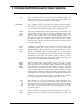
TERMINAL DEFINITIONS AND DESCRIPTIONS .......................................................................................................49
OPTIONAL EQUIPMENT..................................................................................................................................................50
EDMSAT(CC914) .............................................................................................................................................................51
SOLUTION PRINTER INTERFACE (CC812).......................................................................................................................51
SERIAL PRINTER CABLE (CC809)......................................................................................................................................52
SOLUTION PROGRAMMER (CC814)................................................................................................................................52
EDMSTU (CS800) ............................................................................................................................................................52
SOLUTION SYSTEM PROGRAMMING KEY .......................................................................................................................52
(CC810) .............................................................................................................................................................................52
SOLUTION MODEM MODULE (CC811) ...........................................................................................................................52
EDM VOICE RECORDER MODULE (CC888) .......................................................................................................................53
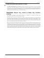
SOLUTION REMOTE KEY SWITCH & RADIO KEY INTERFACE (CC813) ...........................................................................53
ISSUE401.DOC
Electronics Design & Manufacturing
Solution-8 Installation Manual
Page 7
Preface
This manual will explain all aspects of programming the Solution-8 control panel from default to final
commissioning. All system parameters and options are detailed, however suitability is left up to the individual.
Every system can be tailored to meet all requirements quickly and easily. The programming simplicity will make
your installation quick, accurate and rewarding each and every time.
This manual assumes that you are familiar with every feature and operation as detailed in the Operators Manual.
Therefore certain operational procedures have been omitted. A number of new features and improvements have
been introduced in Solution-8 Issue 3. To make the changes easily noticeable we have prefixed each of
them with the following symbol V3.
Introduction
Congratulations on selecting the Solution-8 security control system for your installation. So that you can
obtain the most from your unit, we suggest that you take the time to read through this manual and familiarise
yourself with the numerous outstanding operating and installation features of this system. You will notice that in
all aspects of planning, engineering, styling, operation, convenience and adaptability, we have sought to
anticipate your every possible requirement. Programming simplicity and speed have been some of the major
considerations and we believe that our objectives in this area have been more than satisfied.
The plug in PROGRAMMING KEY has been a major break through in control panel programming. This unique
device offers a much more versatile, accurate and time saving way to configure your systems. The many available
programming methods, cabinet design and flexibility of this security control panel will make installation a breeze
with total satisfaction every time.
NOTE:
A number of new features and improvements have been introduced in Solution-8 Issue 3. To make the
changes easily noticeable we have prefixed each of them with the following symbol
Electronics Design & Manufacturing
V3.
ISSUE401.DOC
Page 8
Solution-8 Installation Manual
Features
The Solution-8 security control panel is microprocessor controlled with the highest degree of integration
ever seen in security control systems to date. This not only means more features but greater reliability and
performance. The design of every feature has been accomplished with continual consideration being given to the
end user and the installer. The control console is straight forward and uncluttered, so as not to complicate its
operation or make programming confusing in any way. Its stylish appearance allows it to easily blend in with
modern and contemporary surroundings.
The cabinet has been laid out to allow for easy conduit entry and has ample room for wiring and a 6.5aH battery.
A dynamic battery tester has been incorporated which performs continual testing and monitoring of the backup
battery's condition and will report any failure through the system console. A battery can no longer be left
accidentally unconnected because the system will detect this failure and report it accordingly.
The Day Alarm feature enables you to monitor the opening of a front door of a shop, or unauthorised access into
a particular area. The remote arming feature gives you the ability to arm your system from any telephone in the
world.
In situations where the main console is installed in a bedroom and the indicators become annoying at night, the
console extinguish mode will automatically turn off all the indicators after sixty seconds. The console indicators
will illuminate the next time a key is pressed or an alarm occurs.
Programming has been made child's play with the introduction of the unique Programming Key. This simple
device exclusive to E.D.M. will revolutionise programming. Labour costs and the possibility of programming
errors will be greatly reduced.
The fully programmable, no compromise output system with its timing and polarity functions has made
interfacing as simple as one, two, three. This allows for easy control of all external devices. The Integrated
Protection System [I.P.S.] has also been incorporated into this revolutionary security control system adding
greater reliability along with incredible tolerance to incorrect wiring or adverse situations. The 24 Hour zones
have been enhanced with the addition of a Fire sound available to the horn speakers. This feature can be of great
use when using smoke detectors so that a distinctly different alert tone is generated from a 24 Hour Fire zone to
that of a standard 24 Hour Burglary zone.
E.D.M. has injected twenty years of knowledge and expertise into the Solution-8 security control system
making it the most flexible, tolerant and easy to operate unit available on the market today. E.D.M. proves again
that an Australian owned company backed by Australians is by far one of the most technically advanced security
manufacturers in the market place today and in the future.
ISSUE401.DOC
Electronics Design & Manufacturing
Solution-8 Installation Manual
Page 9
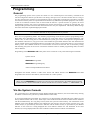
Programming
General
The programming options of this system are stored in a non volatile EEprom. This memory will hold all the
relevant configuration and user specific data even during a total power loss. The data retention time is as long as
ten years without power, therefore no reprogramming will be required after powering the system down. The data
can be altered as many times as required without the need for any additional specialised equipment. This memory
is laid out in numerous locations each of which holds the data for a specific function. In general, the entire
programming sequence will consist of nominating the location then entering or altering the required data. You
will repeat this procedure until all the data has been altered to suit your requirements. The factory default settings
have been selected for Expanded High Speed format.
NOTE:
'15' is the max value that can be programmed into any location.
There are two programming modes. The Installers programming mode and the Operators programming mode.
Both modes have individual access codes and these two codes must always be programmed differently. The
Master Code, as well as being able to arm and disarm the system gives access to the Operators Program mode.
The Installers code however, only gives access to the Installers Program mode and does NOT arm and disarm the
system. Neither of these programming modes are accessible if the system is in the armed state or a previous alarm
memory exists. This condition needs to be corrected before access will be allowed. This is achieved by arming
and disarming the system in succession. It should be noted that when in installer programming mode, all alarms
will be disabled.
Programming of the Solution-8 control panel can be carried out via any of the following four methods.
System console
Solution Programmer
Solution Programming Key
Alarm Link Upload/Download software
Throughout this manual, mention is made of the STAY and AWAY buttons. The Solution hand held
Programmer does not have these buttons, but instead has the * and # symbols.
NOTE:
When using the Solution Programmer any reference in this manual made to the HOME button should be
considered as the * button and the AWAY button considered as the # button. STAY = '*' and AWAY = '#'
Via the System Console
The system must be in a disarmed state with no flashing ZONE alarm memories, this can be achieved by entering
the Master Code then Away (the factory default Master Code is 2580).
To access the Installers Program mode, key in the four or six digit Installer code followed by the AWAY key (the
factory default installer code is 1234). Three beeps will be heard and both the AWAY and the STAY indicators
will flash simultaneously. If a long beep is heard, check the system for alarm memory. The combination of the
MAINS, FAULT and ZONE indicators will indicate the data stored in the first location (location zero). The
number nine(9) is represented by the FAULT indicator and the number zero(0) is represented by the MAINS
indicator. If the value five is being displayed then zone indicator number five will illuminate. If the value
thirteen(13) is being displayed then the FAULT indicator and the ZONE-4 indicator will illuminate.
Electronics Design & Manufacturing
ISSUE401.DOC
Page 10
Solution-8 Installation Manual
Example: 9+4=13
To go to a particular location, key in the location number followed by Away. The indicator will display this
locations data. To move to the next location, press AWAY. The indicator will now display this locations data.
Pressing STAY without previously entering a location number, will step the system back one location. To change
data at the current location key in the new value (remembering that entering the hex values A to F is represented
by the decimal values 10 to 15) followed by STAY. This will store the new data and leave you still positioned at
the same location. To proceed to the next location press the AWAY key. The new locations data will now be
displayed on the indicators.
To exit the Installers Program mode, key in 260 followed by the AWAY key. Two beeps will be heard and the
system will return to normal.
The valid address range for a Solution-8 control panel is 000 to 253.
Via the Solution Programmer
The programmer has five, seven segment displays. The three on the left display the location, and the two on the
right display the data for that particular location. To connect the Solution Programmer, firstly locate the
connections marked KEY. This point can be found centrally located on the Solution-8 printed circuit
board. Observe the triangular markings on the Solution-8 board and line them up with the markings on the
programmers connecting socket. Ensure that the select switch is in the EXT position. When the programmer is
correctly plugged into the Solution-8 board, a beep will be heard and four centre bars on the programmer
will illuminate with either a 'A' or 'U' suffix to indicate the system is Armed or Un-armed. Only when the
Installers Program mode has been accessed will any numerals appear on the displays.
NOTE:
The system must be in a disarmed state with no flashing L.E.Ds indicating alarm memory.
To access the Installers Program mode, key in the four or six digit Installers code followed by # (the default
installers code is factory set to 1234). Three beeps will be heard and the display will show the current data stored
in location zero. If a long beep is heard, check the system for alarm memory. To go to a particular location, key
in the location number followed by #. This locations data will now be displayed. To move to the next location
press #. This will step you to the next location, displaying the appropriate data. Pressing * without previously
entering a location number will step the system back one location. To change data at the current location, key in
the new value (remembering that the hex value A to F is represented by the decimal values 10 to 15) followed by
*. This will store the new data and leave you still positioned at the same location. To proceed to the next location,
press #. The data for this location will now be displayed.
To exit the Installers Program mode, key in 260 followed by #. Two beeps will be heard and the system will
return to normal.
Internal / External
The programmer has a built in programming default key. Use this key to default the control panels data to your
specific requirements. To program the internal key enter normal programming mode and select INT on the
switch. Now all programming alterations will be recorded into your programmers memory key. Once you have
exited programming mode switch to EXT mode. To download the programmers memory to a control panel
simply connect your programmer and switch to INT wait for the activity light to start blinking then switch back to
EXT. The control panel now has a copy of the programmers memory loaded.
ISSUE401.DOC
Electronics Design & Manufacturing
Solution-8 Installation Manual
Page 11
Via the Programming Key
The Solution Programming Key is a unique device that will allow you to easily program your control panel.
Inserting the Programming Key will automatically initiate a data transfer from the Programming Key to the
control panel memory.
If you have a new Programming Key you should first enter the Installers Program mode, configure your system as
per your requirements then insert the Programming Key while still in the Program mode and enter command 262.
This will copy the system data onto your new Programming Key. Exit the program mode by entering command
260, wait two seconds for the activity L.E.D. to return to its normal blinking state and then remove the
Programming Key. This Key will now become your standard data pattern for future programming of your
systems.
It should be noted that when entering the Installers Program Mode, inserting a Programming Key and then
altering any location will cause a simultaneous update of not only the Keys data but also the control panels data.
Therefore, you are not able to alter data in the Programming Key without the same location being altered in the
control panels memory.
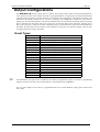
Programming Option Bits
When programming these locations you will notice that there are four alternatives per location. You may select
one, two, three or all of these alternatives for each location, however only one number needs to be programmed.
This number is calculated by adding the option bit numbers together.
Example:
If at location 215 you want options 1, 2 and 4 then simply add the numbers together and the total is the number to
be programmed. In the example the number to be programmed is '7' (1+2+4=7)
Option Bit
1
2
4
8
Program Commands
Description
Forced arming to be allowed
Console panic to be audible
Invalid code tamper to be audible
Extinguish mode
V3
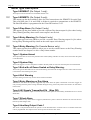
There are several commands that can be invoked to perform the functions as listed below. These commands only
operate whilst you are in the Installers Program mode. To invoke the command enter the commands numerical
code then press the AWAY key, three beeps will be heard and the command will be executed.
NOTE:
These commands do not operate when using Alarm link.
Command
257
258
259
260
261
262
263
264
265
266
Function
Random Select User Codes
Enable and Disable Zone status mode
Test key
Exit program mode
Set back to factory default
Copy the panel memory to the key
Copy the key data to the panel memory
Wipe key
Domestic Dialling Setup
Enable and Disable automatic stepping of locations during programming
Electronics Design & Manufacturing
ISSUE401.DOC
Page 12
Solution-8 Installation Manual
Command 257
This command when entered during programming mode will automatically, randomly select fourteen (14)
different four digit user codes. It should be noted that the master, installer and auxiliary codes are not altered by
this command.
Command 258
This function enables and disables the zone status display mode. If this command is issued from a system console
then the eight ZONE L.E.D.s 1 to 8 will display the zone status accordingly.
When a Solution Programmer is used the zones will be displayed on the seven segment displays from left to
right. The number 1 indicates that a zone is unsealed and a blank display indicates that a zone is sealed.
The third (or centre) display will show either the number 4 or number 8. The number 4 indicates that zones one
to four are being displayed and an eight indicates that zones five to eight are being displayed. Pressing the
AWAY key, toggles the display between zones 1 to 4 and zones 5 to 8. This feature will prove to be very useful
during installation as it allows you to view the status of the zones directly at the panel without having to connect a
temporary console, saving you time and money.
Example:
A 1 in the display indicates the zone is unsealed.
A blank display indicates the zone is sealed.
11411 indicates that zones 1, 2, 3, & 4 are unsealed.
1À8À1 indicates that zones 5 and 8 are unsealed.
Command 259
This command causes a test to be carried out on the Programming Key. This test is non destructive and the data
will remain intact after the test has been completed. One long beep indicates that the Key has failed and three
beeps indicates a successful test. If the Key is removed before the test is completed or the Key fails, its data will
be corrupted. Remember, do not remove the Key while the activity L.E.D. is illuminated or pulsing rapidly.
Command 260
This command is used to exit the Installers program mode after completing your alterations. This is achieved by
entering the command 260 followed by the AWAY key. Two beeps will be heard and the system will return to
normal. This can be done at any programming stage and from any location.
Command 261
This command will configure the system back to the factory default values. This is achieved by entering the
command 261 followed by AWAY. Three beeps will heard indicating a successful operation.
Command 262
This command is used to copy the Solution-8 configuration memory to the Programming Key. Insert the
Key into the socket marked EXTERNAL KEY on the programmer or into the socket marked KEY on the
Solution-8 printed circuit board. Enter the command 262 followed by the AWAY key and three beeps will
be heard. The Solution-8 configuration memory has now been copied to the Key. This feature will prove to
be extremely useful in numerous situations.
Command 263
This command is used to copy data from the Programming Key to the Solution-8 configuration memory.
Insert the Program Key into the socket on the programmer and enter the command 263 followed by the AWAY
key. Three beeps will be heard and the data in the Key will be transferred to the Solution-8 configuration
memory.
ISSUE401.DOC
Electronics Design & Manufacturing
Solution-8 Installation Manual
Page 13
Command 264
This command erases all data from the Programming Key. Insert the Key into the programmer and enter the
command 264 followed by the AWAY key. Three beeps will be heard and all data from the Key will be erased.
This feature is useful if you wish to give a Key to someone else without them having access to the previous data.
V3
Command 265
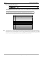
Command 265 has been added to make the programming of Domestic Dialling a one step operation. When in
Installers programming mode press 265 followed by the AWAY key. This will automatically set the following
locations as below.
Location
Location 49
Location 50
Location 52 - 55
Location 196 & 197
Location 198 & 199
Location 200
Location 201
Location 203
Location 204
Location 205
Location 206
Location 207
Location 208 & 209
Location 252 & 253
Description
Handshake
Transmission Format
Unit ID
AC Fail
Low Battery
Open Report
Close Report
Alarm Restore
Trouble Code
Trouble Restore
Bypass Code
Bypass Restore
Keyboard Tamper
First Test Report
Setting
2 (1400 Hz)
11 (Domestic)
0001
0&0
0&0
0
0
0
0
0
0
0
0
0
No other locations will be altered when the command 265 is issued. This means that things such as entry and exit
times, siren run time etc will not change.
Command 266
This feature enables or disables the automatic stepping of locations while programming. When enabled via the
Solution Programmer the decimal point of the left most display will reflect the mode of operation. If the
decimal point is illuminated then Auto Step mode is active. An automatic increment of the location being
programmed will occur as soon as the STAY button is pressed positioning you at the next location ready for
programming. If the decimal point is extinguished, the Auto Step mode is disabled. The next programming
location will need to be manually selected.
Electronics Design & Manufacturing
ISSUE401.DOC
Page 14
Solution-8 Installation Manual
Example:
Entering the primary telephone number 02 pause 631-0555. With auto step enabled (decimal point illuminated).
0 + AWAY.
(This will put you at location 0 being the start location required).
10 +
3+
+
+ 2+
+1+
+5+
+ 13 +
+ 10 +
+6+
+5+
+
+5
+0+
Example:
With auto step disabled (decimal point extinguished). 0 + AWAY
(This will put you at location 0 being the start location required).
10 +
+
+1+
+
+
+2+
+
+6+
+
+3+
+
+ 10 +
+
+5+
+
+5+
+ 13 +
+
+5+
+0+
As you can see from the above examples, Auto Step mode is a very useful feature when programming successive
locations.
ISSUE401.DOC
Electronics Design & Manufacturing
Solution-8 Installation Manual
Page 15
Zone Types
The zone inputs Z1 to Z8 will need to be programmed to an appropriate zone type. A zone type defines the type
of action that a zone will take when triggered. As you can see from the following list, zones can be instant,
delayed or 24 hour, with numerous options.
When a zone type is selected with the Stay mode option, it will be automatically isolated when the system is
armed in Stay mode. This feature allows easy arming of the perimeter detection zones with all internal detection
zones disabled.
A zone selected for instant will have no entry delay unless the previous zone is already entry timing. It will then
take on the remaining entry time from the previous zone as the handover time.
Delay 1 zone types will have their entry delay time specified in locations 228 and 229. Delay 2 zone types will
have their entry delay time specified in locations 230 and 231. A delay zone when triggered will delay for the
specified time before alarming.
NOTE:
If the EDMSAT is connected then the unique fire sound will not be heard unless there is an additional horn
speaker connected to SPK1 or SPK2.
Any zone programmed to be a fire zone will not cause the bell output to trigger when an alarm has been
activated. In the case where a fire zone alarms, the siren output will sound a fire warning tone. This unique sound
allows you to easily distinguish the difference between a fire and a burglary. If an output is required for Fire
alarms, see programmable outputs where you can configure a output to operate whenever a Fire Alarm occurs.
NOTE:
Instant zones will automatically accept handover delay from previous zones.
Also see Location 202 if handover delay to all instant zones is required.
A zone programmed as 99 will force the relative zone to appear as if it were normal. No end of line resistor is
required and the keypad indicator will show a normally sealed zone.
An unused zone can be programmed to type 99 and therefore eliminate the
need to fit an end of line (EOL) resistor.
Electronics Design & Manufacturing
ISSUE401.DOC
Page 16
Solution-8 Installation Manual
Zone Configuration Table
Opt
1
2
3
4
5
6
7
8
9
10
11
12
Typ
0
0
0
0
0
0
0
0
0
0
0
0
Instant
Standard Instant
Lockout-siren
Lockout dialler
Lockout siren + lockout dialler
Silent
Silent + lockout dialler
Stay mode
Stay mode + silent
Stay mode + silent + lockout dialler
Stay mode + lockout siren
Stay mode + lockout dialler
Stay mode + lockout siren + lockout
dialler
Opt
1
2
3
4
5
6
7
8
9
10
11
12
Typ
2
2
2
2
2
2
2
2
2
2
2
2
Delay 2
Standard Delay-2
Lockout-siren
Lockout dialler
Lockout siren + lockout dialler
Silent
Silent + lockout dialler
Stay mode
Stay mode + silent
Stay mode + silent + lockout dialler
Stay mode + lockout siren
Stay mode + lockout dialler
Stay mode + lockout siren + lockout
dialler
Opt
1
2
3
4
5
6
7
8
9
10
Typ
1
1
1
1
1
1
1
1
1
1
Delay 1
Standard Delay-1
Lockout-siren
Lockout dialler
Lockout siren + lockout dialler
Silent
Silent + lockout dialler
Stay mode
Stay mode + silent
Stay mode + silent + lockout dialler
Stay mode + lockout siren
Opt
1
2
3
4
5
6
7
8
9
10
Typ
3
3
3
3
3
3
3
3
3
3
11
12
1
1
Stay mode + lockout dialler
Stay mode + lockout siren + lockout
dialler
Opt
9
Typ
9
24 Hour
Standard 24 Hour
Lockout-siren
Lockout dialler
Lockout siren + lockout dialler
Silent
Silent + lockout dialler
Fire sound
Fire sound + lockout siren
Fire sound + lockout dialler
Fire sound + lockout siren + lockout
dialler
Spare Zone
Unused Zone
ISSUE401.DOC
Electronics Design & Manufacturing
Solution-8 Installation Manual
Page 17
Output Configurations
The Solution-8 has four outputs, OUT1 to OUT4, and a console beeper which are fully programmable for
event, polarity and time. Each output will need to be programmed for an appropriate event type which defines
when the output will operate. The next function to be selected is the configuration. This defines the polarity and
function for the output terminal such as one shot or pulsing. If the configuration selected was a one shot or
pulsing type, then the time parameter will need to be defined. This sets the time that the output operates for. Eg If
pulse is selected, then the output will be low for the time set and then high for the same time, repeating for as
long as the event type is valid. If a one shot configuration type is selected, the time option will set the duration of
the output. The time option can be set from as low as 200ms to as long as 51 seconds. Event types 8 & 9 can only
be triggered when the system is disarmed.
Event Types
Event Code
0
0
0
0
0
1
2
3
4
5
6
7
8
9
10
11
12
13
14
15
V3
Function
EDMSAT
(only available on output 1)
EDMSTU
(only available on output 2)
Day alarm
(only available on output 3)
Entry warning (only available on output 4)
Entry warning (only available on console buzzer)
System Armed in Away or Stay mode
System Armed in Stay Mode
Exit with all zones sealed or entry warning
Exit warning
Entry warning or Day alarm
All signals transmitted ok (kiss off)
Silent alarm
Auxiliary code 1
Auxiliary code 2
AC Failure
Low battery
Zone unsealed
Fire Zone or Fire Alarm
Console Panic or Duress
Remote control
Four additional event types are now available for use with the programmable outputs. In Version 2, programming
Output 1(Location 232) with a zero would enable it to communicate with an EDMSAT.
The rest of the outputs can now also be programmed with zeros to obtain different output types as listed in the
above table.
Electronics Design & Manufacturing
ISSUE401.DOC
Page 18
Solution-8 Installation Manual
Event Type Description
Type 0-EDMSAT (On Output 1 only)
This output controls all functions of an EDM satellite siren.
V3
Type 0-EDMSTU (On Output 2 only)
This output type has been added to allow for serial connection to the EDMSTU Securitel Unit.
This serial link, plus 13.8v and GND is all that is required to communicate to the EDMSTU.
The Hard ID number is programmed in the Client ID locations 52-55.
V3
Type 0-Day Alarm (On Output 3 only)
This output type has been added to provide a separate Day alarm output for jobs where having
Entry Warning and Day alarm on the same output is not desired.
V3
Type 0-Entry Warning (On Output 4 only)
This output type has been added to provide a separate Entry Warning output for jobs where
having Entry Warning and Day alarm on the same output is not desired.
V3
Type 0-Entry Warning (On Console Buzzer only)
This output type has been added to allow you to use the console buzzer as the Entry Warning
sounder and to use Output 3 to drive a Day Alarm sounder.
Type 1-System Armed
This output activates as soon as the panel becomes armed (during and after exit time). It will reset when the panel
is next disarmed.
Type 2-System Stay
This event triggers as soon as the panel is armed in the Stay mode. It will reset when the panel is next disarmed.
Type 3-Exit with all Zones Sealed or Entry Warning.
This event type has dual functions. It will activate during exit time when all eight zones are sealed. The next time
it will activate will be during entry time.
Type 4-Exit Warning
Activates during exit time only. Zones can be sealed or unsealed.
Type 5-Entry Warning or Day Alarm
This feature will cause the output to trigger for Day alarm when the panel is disarmed. It will also trigger for
entry warning when the panel is being disarmed during the entry period. Day alarm zones need to be selected in
location 227.
Type 6-All Signals Transmitted Ok (Kiss Off)
This feature will cause the output to activate once the control panel has successfully transmitted all of its stored
alarm data.
Type 7-Silent Alarm
Activates whenever any silent alarm is triggered, whether the system is armed or disarmed. It will reset the next
time the system changes state.
Type 8-Auxiliary Output Code 1
This event is only functional while the system is in the disarmed state. Locations 152 to 157 defines where this
code is programmed. This output can be used to operate an electric door strike.
ISSUE401.DOC
Electronics Design & Manufacturing
Solution-8 Installation Manual
Page 19
Type 9-Auxiliary Output Code 2
The conditions for this output are the same as Auxiliary output code 1. Locations 158 to 163 defines where this
code is programmed. This output can be used to operate an electric door strike.
Type 10-A.C. Fail
This output will activate as soon as the A.C. mains is removed, whether the system is armed or disarmed. It will
reset when the A.C. is re-connected to the system.
Type 11-Low Battery
This output will activate as soon as the system detects the battery voltage to be less than 10.5 volts. This is true
whether the system is armed or disarmed.
Type 12-Zone Unsealed
This output will activate as soon as any zone becomes unsealed whether the system is armed or disarmed. It will
reset when all zones are sealed.
Type 13-Fire Alarm or Fire Zone
This output is activated whenever a 24 hour zone selected for Fire tone is triggered. This is true whether the
system is armed or disarmed. This output will reset at the end of siren time or when the 'One-Shot Timer' times
out.
Type 14-Console Panic / Duress
This output activates when the system is being disarmed using the duress feature or when any two buttons in the
same horizontal plane are pressed simultaneously. It will reset when the system is next armed.
Type 15-Remote Control
This output can be activated from a personal computer via the ALARM LINK software or it can be toggled by
using a master code function.
Polarity Configurations
Polarity configurations that pulse will generate a repetitive pulsing output with the time interval set by the time
parameter. The one shot configurations will generate one timed output when the specified event occurs.
Option
0
1
2
3
4
5
6
Description
Output not used
Normally open circuit, going low
Normally low, going open circuit
Normally open circuit, pulsing low
Normally low, pulsing open circuit
Normally open circuit, one-shot low
Normally low, one-shot open circuit
NOTE:
Options 1 to 4 will remain active for the duration of the selected event.
Time
This parameter should be programmed for polarity configurations that pulse or have one-shot operation. The
range can be set from 200ms to 51 seconds in increments of 200ms. Use the time parameter to set how long an
event will occur for Polarity Options 5 & 6 or the pulse rate for options 3 & 4.
If you have selected an output for one shot to operate a door strike then the Time parameter is used to set how
long the strike will operate for.
Electronics Design & Manufacturing
ISSUE401.DOC
Page 20
Solution-8 Installation Manual
Programming Locations
The default value for each location are indicated by the hollow numbers shown after each location title. If a
value outside the recommended range is selected then the option will revert to the factory default setting. A zero
'0' programmed in any location will always disable the function.
For options requiring more than one location, multiple zeros '0' will need to be entered.
All examples assume the client number to be 5678.
Primary Telephone Number
Locations 00-15
0000000000000000
NOTE:
Substitute '10' for zeros, as a '0' indicates end of the phone number
This number will be called three times in an attempt to contact the monitoring station. If unsuccessful, the
secondary number will then be called three times as well. This procedure will be repeated only once again (ie
maximum of twelve call attempts) after ten minutes if the first six attempts were unsuccessful.
A '0' is used to indicate the end of the phone number. Therefore the dialling sequence will be terminated when a
'0' appears. Entering the value '13' will initiate a 4 second pause in the dialling sequence.
Secondary Telephone Number
Locations 16 - 31
0000000000000000
See primary telephone number for programming details.
Callback Number
Locations 32 - 47
0000000000000000
This location contains the telephone number that will be called when upload/download is requested. When
triggered, the Solution-8 will call this number to establish a communications link with the remote
computer. The computer must be running EDM ALARM LINK software.
ISSUE401.DOC
Electronics Design & Manufacturing
Solution-8 Installation Manual
Page 21
Dialling Format
2
Location 48
The method for dialling telephone numbers is entered here. Options 4 and 5 will alternate the dialling sequence
between DTMF and decadic if the call to the monitoring station was not successful.
#
1
2
3
4
5
Format
DTMF (Touch Tone)
Australian decadic (pulse dialling)
New Zealand decadic (pulse dialling)
Alternate between DTMF and Australian Decadic
Alternate between DTMF and New Zealand Decadic
NOTE:
The alternating sequence is as follows,
DTMF - Decadic - DTMF - Decadic - DTMF - Decadic
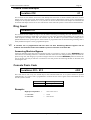
Handshake Tone
1
Location 49
This location sets the type of handshake required before data transmissions to the monitoring station will begin.
#
1
2
3
4
5
Handshake Tone
Hi-Lo handshake (High speed DTMF)
1400Hz handshake (Low speed Ademco TX at 1900Hz
2300Hz handshake (Low Speed Sescoa TX at 1800Hz
No Handshake required (use this option carefully)
Pager Handshake
Electronics Design & Manufacturing
ISSUE401.DOC
Page 22
Solution-8 Installation Manual
Transmission Format
Location 50
V3
1
Enter the desired transmission format here. This location selects the data format that will be transmitted to the
monitoring receiver.
NOTE:
Please note that some formats may only work to certain monitoring station receivers.
#
1
2
3
4
5
6
7
8
9
10
11
12
13
14
15
V3
Function
DTMF Expanded High Speed
DTMF Expanded High Speed with checksum
4 + 2 DTMF
4 + 2 DTMF with checksum
4 + 2 Pulsed
4 + 2 Pulsed with checksum
4 +1 Pulsed Universal
4 +1 Pulsed Expanded
3 + 1 Pulsed Universal
3 + 1 Pulsed Expanded
Domestic
Basic Pager
Advanced Pager
4 + 2 Express
Synthesised Voice
The Synthesised Voice option is a new transmission format which has been incorporated into the domestic dialling
option. If Location 50 is programmed with a "15" then all alarm information will be reported verbally via the EDM
Synthesised Voice Module. This module will need to be plugged into the Modem pins on the circuit board and
therefore will mean that the upload / download option will not be available in this mode.
ISSUE401.DOC
Electronics Design & Manufacturing
Solution-8 Installation Manual
Page 23
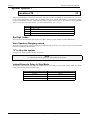
Transmission Speed
2
Location 51
Altering this location will only effect Transmission Format (location 50).
Options 5 to 10 and sets the pulsing rate for the transmitted data.
The following is a list of compatible receivers, their specific handshake tones and transmission formats.
#
1
2
3
4
5
6
Format Description
1 pulse per second (EDM super slow)
10 pulses per second
15 pulses per second
20 pulses per second
20 pulses per second fixed digit length (FDL)
40 pulses per second
Receiver
Silent Knight
Ademco Slow
Transmission Format
10pps, 1400Hz HS, 3+1, 3+2, 4+1, 4+2
Sescoa
Franklin
DCI
Vertex
20pps, 2300Hz HS, 3+1, 3+2, 4+1, 4+2
Silent Knight FAST
20pps, 2300Hz HS, 3+1, 3+2, 4+1, 4+2
Ademco
10pps, 1400Hz HS, 3+1, 3+2, 4+1, 4+2
20pps, 2300Hz HS, 3+1, 3+2, 4+1, 4+2
40pps, 1400Hz HS, 3+1, 3+2, 4+1, 4+2
DTMF, Hi-Low Hs, Expanded Format, 4 +2 Express
FBI
10pps, 1400Hz HS or 2300Hz HS, 3+1, 3+2, 4+1, 4+2
20pps, 1400Hz HS or 2300Hz HS, 3+1, 3+2, 4+1, 4+2
40pps, 1400Hz HS or 2300Hz HS, 3+1, 3+2, 4+1, 4+2
DTMF, 1400Hz HS or 2300Hz or Hi-Low, 4 +2 or 4 +2 + CS
DTMF, Hi-Low HS, Expanded Format
If your receiver is not listed above do not despair, there are many combinations of formats, speeds and handshake
tones. Try a few combinations and you will more than likely find the one that works for your receiver.
It should be noted that some formats offer much more information than others so take the time to consider the
many alternatives being offered.
1WARNING
Do not substitute the value '10' for a '0' in any location between 52 and 163.
Electronics Design & Manufacturing
ISSUE401.DOC
Page 24
Solution-8 Installation Manual
Customer Client Code
0000
Locations 52 - 55
This code is transmitted to identify the calling unit. Enter the desired client number in the four locations
provided. For 3 + 1 and Pager formats, location 52 is ignored and the first digit of the Client Code required
must go in location 53. When using domestic format then the identification beep is selected by the number in
location 55 thus allowing domestic format the ability to identify 15 different systems calling the same number.
Installer Code
123400
Locations 56 - 61
This code can be four or six digits long and is used to enter the Installers Programming mode. The default code is
123400 however since trailing zeros need not be entered, 1234 will work for both 4 or 6 digit code length modes.
1
WARNING
DO NOT program "10" for "0" in the Master or User codes.
USER 1 (Master Code)
Locations 62 - 67
258000
This code will be needed when specialised functions are performed from the operators mode. The master code
holder is the only person that can alter user codes.
ISSUE401.DOC
Electronics Design & Manufacturing
Solution-8 Installation Manual
Page 25
User Codes
0...0
Locations 68 - 163
These are the 14 user codes available that can be altered at will by the master code holder. If Openings and
Closing's (locations 200 and 201) are programmed, then any code being used to arm and disarm the system, will
be transmitted to the monitoring station as the appropriate user number.
User Number
User 2
User 3
User 4
User 5
User 6
User 7
User 8
User 9
User 10
User 11
User 12
User 13
User 14
User 15
Location
68 to 73
74 to 79
80 to 85
86 to 91
92 to 97
98 to 103
104 to 109
110 to 115
116 to 121
122 to 127
128 to 133
134 to 139
140 to 145
146 to 151
Any user code starting with '00' will only arm the system. This can be helpful when you need to give a code to
someone who is only allowed to arm but not disarm the system such as a cleaner or guest.
NOTE:
If 6 digit codes are required a '1' must be programmed into location 214.
Auxiliary Codes
There are two auxiliary codes which are capable of triggering any two of the four programmable outputs. As an
example these codes could be used to unlock a door to allow access into a secured area. Outputs can only be
triggered from these codes while the system is in the disarmed state. An appropriate output will have to be
programmed so that this function can operate. These codes can be changed from the operators programming
mode (Master code + 1) as they are treated as user codes 16 and 17 respectively. These codes do not arm or
disarm the system. Their only function is to operate the programmable outputs.
Auxiliary Code
Aux code 1
Aux code 2
Location
152 to 157
158 to 163
Electronics Design & Manufacturing
ISSUE401.DOC
Page 26
Solution-8 Installation Manual
Zone Configuration Table
Opt
1
2
3
4
5
6
7
8
9
10
11
12
Typ
0
0
0
0
0
0
0
0
0
0
0
0
Instant
Standard Instant
Lockout-siren
Lockout dialler
Lockout siren + lockout dialler
Silent
Silent + lockout dialler
Stay mode
Stay mode + silent
Stay mode + silent + lockout dialler
Stay mode + lockout siren
Stay mode + lockout dialler
Stay mode + lockout siren + lockout
dialler
Opt
1
2
3
4
5
6
7
8
9
10
11
12
Typ
2
2
2
2
2
2
2
2
2
2
2
2
Delay 2
Standard Delay-2
Lockout-siren
Lockout dialler
Lockout siren + lockout dialler
Silent
Silent + lockout dialler
Stay mode
Stay mode + silent
Stay mode + silent + lockout dialler
Stay mode + lockout siren
Stay mode + lockout dialler
Stay mode + lockout siren + lockout
dialler
Opt
1
2
3
4
5
6
7
8
9
10
Typ
1
1
1
1
1
1
1
1
1
1
Delay 1
Standard Delay-1
Lockout-siren
Lockout dialler
Lockout siren + lockout dialler
Silent
Silent + lockout dialler
Stay mode
Stay mode + silent
Stay mode + silent + lockout dialler
Stay mode + lockout siren
Opt
1
2
3
4
5
6
7
8
9
10
Typ
3
3
3
3
3
3
3
3
3
3
11
12
1
1
Stay mode + lockout dialler
Stay mode + lockout siren + lockout
dialler
Opt
9
Typ
9
24 Hour
Standard 24 Hour
Lockout-siren
Lockout dialler
Lockout siren + lockout dialler
Silent
Silent + lockout dialler
Fire sound
Fire sound + lockout siren
Fire sound + lockout dialler
Fire sound + lockout siren + lockout
dialler
Spare Zone
Unused Zone
ISSUE401.DOC
Electronics Design & Manufacturing
Solution-8 Installation Manual
Page 27
Zone Configurations
0...0
Locations 164 - 195
Each zone has four programming locations allocated to it. The first of these locations contains the character for
the zone option (1 to 12), the second of these locations contains the character for the zone type (0 to 3). The third
location contains the channel number for the alarm reporting and the fourth location contains the expansion code.
Example:
To program Zone 1 as a delay-1, lockout siren, lockout dialler : Enter '4' into location 164 and a '1' into location
165. To make Zone 1 report on channel one to a high speed receiver, program a '1' into location 166 and a '9' into
167.
Channel
The code entered in this location will determine on which channel alarms will be reported. For 3+1 or 4+1
formats this location has no effect.
Expansion
If you do not require alarm reports from a zone, program its expansion code to '0'. The dialler will not be
triggered by alarms on a zone that has an expansion code of '0.' The zone will function normally otherwise.
In the 3+1 and 4+1 formats this location selects the actual code to be sent.
If you want the zone to report an alarm then you must specify a digit other than '0' (zero) for the expansion code.
When using HI-SPEED expanded format, program a '9' as the expansion code, this will ensure correct
transmissions.
If you are using 4+2 format, the expansion code will be sent first as the 10s digit and the channel number will
follow as the units digit.
Zone
Number
Zone 1
Location
Number
164 to 167
Zone 2
168 to 171
Zone 3
172 to 175
Zone 4
176 to 179
Zone 5
180 to 183
Zone 6
184 to 187
Zone 7
188 to 191
Zone 8
192 to 195
Option
Type
1
1
1
1
1
1
1
1
1
0
0
0
0
0
0
3
Default
Channel
1
2
3
4
5
6
7
8
Expansion
9
9
9
9
9
9
9
9
Note:
The Zone configuration table is presented on the previous page.
Electronics Design & Manufacturing
ISSUE401.DOC
Page 28
Solution-8 Installation Manual
A.C. Fail Code
19
Locations 196 - 197
Location 196 holds the reporting channel and location 197 holds the expansion code. For HI-SPEED expanded
format use any number other than '0' in the expansion code. The reporting channel should be programmed with a
'1' to comply with the standard HI-SPEED expanded transmission format.
If you do not require an A.C. fail report then program a '0' in the expansion code.
Location
196
197
Description
Reporting code CH
Expansion code AC
Example:
High-Speed Expanded
5678 1555 5555 6
=
3 + 1 Format
=
678 AC
4 + 2 Format
=
5678 AC CH
Low Battery
29
Locations 198 - 199
A low battery report will be sent when the systems battery voltage falls below 10.5 volts or when a Dynamic
Battery test detects a low capacity battery. Location 198 holds the reporting channel and location 199 holds the
expansion code. For HI-SPEED expanded use any number other than '0' in the expansion code. The reporting
channel should be programmed with a '2' to comply with the standard HI-SPEED expanded transmission format.
If you do not require a Low battery report then program a '0' in the expansion code.
A low battery restore will not be reported until a Dynamic Battery test occurs and the battery voltage is above
10.5 volts with acceptable capacity.
Location
198
199
Description
Reporting code CH
Expansion code LB
Example:
High-Speed Expanded
ISSUE401.DOC
5678 5155 5555 6
=
3 + 1 Format
=
678 LB
4 + 2 Format
=
5678 LB CH
Electronics Design & Manufacturing
Solution-8 Installation Manual
Page 29
Opening Report Code [OP]
8
Location 200
An opening code is sent when the system is disarmed from the AWAY mode only. If an expanded format is
selected then this code will be used as the expansion code and the user number that disarmed the system will
follow in the same transmission. If an opening report is not required then a '0' should be programmed in this
location.
V3
NOTE:
Open and close codes can be sent in home mode. See location 202.
If an opening code is programmed without a closing code then an opening report will be sent only if a previous
alarm had occurred. This is an ideal feature for detecting if an alarm occurs as the premises are being opened.
Example:
High-Speed Expanded
5678 u222 2222 2
=
3 + 1 Format
=
678 OP
4 + 2 Format
=
5678 OP u
Where u is the user identification number.
Closing Report Code [CL]
9
Location 201
A closing code is sent at the end of exit time when the system is armed in the AWAY mode only (not HOME
mode). If an expanded format is selected then this code will be used as the expansion code and the user number
that armed the system will follow in the same transmission. If a closing report is not required then a '0' should be
programmed in this location.
Example:
High-Speed Expanded
5678 u444 4444 4
=
3 + 1 Format
=
678 CL
4 + 2 Format
=
5678 CL u
Where u is the user identification number.
Electronics Design & Manufacturing
ISSUE401.DOC
Page 30
Solution-8 Installation Manual
Advanced Options
0
Location 202
When programming this location you will notice that there are four alternatives. You may select one, two, three
or all of these alternatives, however only one number needs to be entered. This number is calculated by adding
the option bit numbers together. Simply add the numbers together and the total is the number to be programmed.
Enter a seven (7) if you require options 1, 2 and 4 simultaneously (ie. 1+2+4=7).
V3
OPT
1
2
4
8
Function
Send open & close reports when in Stay Mode
Send test reports only if the system is armed
Illuminate all indicators during entry time
Handover delay to all instant zones
V3
Send Open & Close Reports when in Stay Mode
Programming this location will cause the Solution panel to transmit Open and Closing reports when the
panel is in the STAY mode.
Bypass and trouble reports will not be transmitted when in the STAY mode.
Test Reports (only when armed)
Send test reports only if system is armed, when programmed means that it is no longer necessary to send a test
report as well as an opening and closing report every day. Set the option and program the test report to be sent
when the client is normally opened. During the working week most commercial premises would be open and
therefore a test is not necessary as open and close codes would have been sent. On the weekend however, the
panel would be armed and thus test reports will be sent at the programmed time.
Illuminate Indicators
Illuminate all indicators during entry time will cause the Solution panel to turn on all of the console
indicators as soon as the entry timer starts. This will allow the user to easily locate the console and keys when it is
in a dark location. As soon as the system is successfully disarmed all the indicators will revert back to there
normal condition.
Handover Delay
Handover delay to all instant zones will cause all instant zones to have handover delay provided that an entry
zone has been triggered first. If this option is not set and an entry zone is violated, it will handover the delay to
the next zone in sequence. If the sequence is broken before the entry time expires then an alarm will occur.
Setting this option will mean that provided an entry zone is broken first, the entry delay will be handed over to all
instant zones regardless of the order they are violated in.
ISSUE401.DOC
Electronics Design & Manufacturing
Solution-8 Installation Manual
Page 31
Restore Code [AR]
9
Location 203
This location holds the restoral code and is used as the expansion code in expanded formats. It will be followed
by an event code identifying the zone or event that restored. This restoral code is also used for AC, LB and Panic
alarms. If restores are not required then a '0' should be programmed in this location.
Example:
High-Speed Expanded
5678 3555 5555 7
=
3 + 1 Format
=
678 AR
4 + 2 Format
=
5678 AR CH
Trouble Code [T]
9
Location 204
A trouble report will be sent at the end of exit time to indicate that one or more zones have been automatically
isolated by the system.
Example:
High-Speed Expanded
5678 1555 5555 5
=
3 + 1 Format
=
678 T
4 + 2 Format
=
5678 T CH
Trouble Restore Code [TR]
9
Location 205
A trouble restore will be sent for burglary zones when they reseal or when the system is next disarmed. A 24 hour
zone will only restore when it reseals.
Example:
High-Speed Expanded
5678 3555 5555 5
=
3 + 1 Format
=
678 TR
4 + 2 Format
=
5678 TR CH
Electronics Design & Manufacturing
ISSUE401.DOC
Page 32
Solution-8 Installation Manual
Bypass Code [B]
9
Location 206
A bypass report will be sent at the end of exit time for zones that have been manually isolated. Bypass reports are
not sent when the system is armed in Stay mode. 24 hour zones cannot be isolated therefore they will never send
bypass reports.
Example:
High-Speed Expanded
5678 1555 5555 3
=
3 + 1 Format
=
678 B
4 + 2 Format
=
5678 B CH
Bypass Restore Code [BR]
9
Location 207
A bypass restore will be sent when the system is next disarmed. If Bypass restore is not programmed then it can
be assumed when an opening report is transmitted. All Bypassed zones are automatically cleared when the
control panel is next disarmed.
Example:
High-Speed Expanded
5678 3555 5555 7
=
3 + 1 Format
=
678 AR
4 + 2 Format
=
5678 AR CH
Invalid Code Tamper
39
Locations 208 - 209
This code will be transmitted when the number of incorrect codes entered equals the number programmed in
location 210. If a restore code is programmed in location 203 the restore signal will be transmitted the next time
the system is armed.
Location
208
209
Description
Reporting channel CH
Expansion code CT
Example:
High-Speed Expanded
ISSUE401.DOC
5678 5515 5555 1
=
3 + 1 Format
=
678 CT
4 + 2 Format
=
5678 CT CH
Electronics Design & Manufacturing
Solution-8 Installation Manual
Page 33
Invalid Code Attempts
6
Location 210
This location sets the number of incorrect code attempts that will cause an alarm condition and send a console
tamper report to the control room. Each time the system is armed or disarmed the counter is reset. The number of
attempts can be anywhere between 1 to 15. If you enter '0' into this location then code attempts are unlimited and
an invalid code tamper will never be sent. This function works when the system is in the armed or disarmed state.
Ring Count
Location 211
This location sets the number of rings to wait for before answering an incoming call. This should be set at an
acceptable level bearing in mind that a ring count of 15 (30 rings) represents approximately 90 seconds for an
AXE telephone exchange. Note that this location only has an effect if you select remote arming and or
upload/download in the system options. If this location is programmed with '0' then answering incoming calls is
totally disabled irrespective of any programmed options.
V3
If Location 211 is programmed with the value 15 then Answering Machine bypass will be
enabled. This function used to be enabled in previous versions in location 202.
Answering Machine Bypass
Answering machine bypass has been incorporated so that it is possible to connect up with a Solution panel
when there is an answering machine or a facsimile machine on the same line. Simply call the panel and allow the
phone to ring once, then hang up. If you then call again within 45 seconds the Solution panel will answer the
call on the first ring and you will have a connection. This will prevent the answering machine or facsimile from
answering the call.
Console Panic Code
29
Locations 212 - 213
This code will be sent if any two outside keys in the same horizontal row on a system console are pressed
simultaneously. If a restore code is programmed in location 203 the restore signal will be transmitted the next
time the system is armed.
Location
212
213
Description
Reporting channel CH
Expansion code CT
Example:
High-Speed Expanded
5678 5155 5555 1
=
3 + 1 Format
=
678 P
4 + 2 Format
=
5678 P CH
Electronics Design & Manufacturing
ISSUE401.DOC
Page 34
Solution-8 Installation Manual
System Options 1
4
Location 214
When programming this location you will notice that there are four alternatives. You may select one, two, three
or all of these alternatives, however only one number needs to be entered. This number is calculated by adding
the option bit numbers together. Simply add the numbers together and the total is the number to be programmed.
Enter a seven (7) if you require options 1, 2 and 4 simultaneously (ie. 1+2+4=7).
OPT
1
2
4
8
Function
Six Digit Code
Horn speakers to have burglary sound number two.
"0" is allowed to arm the system
Instant zones to have Delay-2 when armed in Stay mode.
Six Digit Codes
This option sets the maximum code length to six digits, offering a larger number of code combinations.
Horn Speakers Burglary sound
This option when selected changes the burglary sound allowing you to have two systems in the same area and still
maintain individuality between them.
"0" to Arm the system
This option if selected, enables the fast arm feature.
NOTE:
0 + AWAY can arm the system but it cannot disarm the system.
Instant Zones to Delay in Stay Mode
This option when selected will cause all instant zones to have Delay-2 when armed in Stay mode. Stay mode
zones will have entry times as shown below.
Zone Type
Delay-1
Delay-2
24 Hour
Instant
ISSUE401.DOC
Entry Time when in Stay Mode
Delay-1
Delay-2
Nil
Delay-2
Electronics Design & Manufacturing
Solution-8 Installation Manual
Page 35
System Options 2
7
Location 215
When programming this location you will notice that there are four alternatives. You may select one, two, three
or all of these alternatives, however only one number needs to be entered. This number is calculated by adding
the option bit numbers together. Simply add the numbers together and the total is the number to be programmed.
Enter a seven (7) if you require options 1, 2 and 4 simultaneously (ie. 1+2+4=7).
OPT
1
2
4
8
Function
Forced arming to be allowed
Console panic to be audible
Invalid Code tamper to be audible
Extinguish the console display after 60 seconds
Forced Arming
This option if selected allows the user to arm the system with zones unsealed. When this option is not selected
then all zones will have to be sealed before the user is allowed to arm the system. This feature is ignored if the
system is to be remotely armed via a telephone.
Console Panic
This option when selected causes the siren to sound if a console panic is triggered.
Code Tamper
This option when selected causes the sirens to sound if an invalid code tamper is detected.
Console Display
This feature when selected will extinguish all of the console indicators and buzzers. This is especially handy
when a system console is located in a bedroom and the indicators become annoying.
Console Duress
19
Locations 216 - 217
This code is transmitted when a duress alarm is invoked by adding the digit 9 to the end of your code during a
disarming operation.
Location
216
217
Description
Reporting channel CH
Expansion code D
Example:
High-Speed Expanded
5678 1555 5555 1
=
3 + 1 Format
=
678 D
4 + 2 Format
=
5678 D CH
Electronics Design & Manufacturing
ISSUE401.DOC
Page 36
Solution-8 Installation Manual
Dialler Options 1
0
Location 218
When programming this location you will notice that there are four alternatives. You may select one, two, three
or all of these alternatives, however only one number needs to be entered. This number is calculated by adding
the option bit numbers together. Simply add the numbers together and the total is the number to be programmed.
Enter a seven (7) if you require options 1, 2 and 4 simultaneously (ie. 1+2+4=7).
OPT
1
2
4
8
Function
Disable the dialler.
Enable smart lockout.
Allow horn speaker beeps for radio key operation.
Extend zone response time from 100ms to 400ms.
Disable the dialler
This option when set will disable all dialler operations but will still accept upload/download requests.
Enable smart lockout
This feature allows the control panel to remove any locked out zones from the lockout list only while the sirens
are running. This feature allows a monitoring station to receive codes from previously locked out zones during
siren time.
Allow horn speaker beeps for radio key operation
This feature will enable horn speaker beeps only to be heard when the system is armed via a radio key. Devices
connected to the Bell output will not be audible.
Extend zone response time from 100ms to 400ms
This option selects the zone response time for all eight input zones. A zone will have to be broken for the
prescribed time before alarming.
Dialler Options 2
2
Location 219
When programming this location you will notice that there are four alternatives. You may select one, two, three
or all of these alternatives, however only one number needs to be entered. This number is calculated by adding
the option bit numbers together.
Simply add the numbers together and the total is the number to be programmed. Enter a seven (7) if you require
options 1, 2 and 4 simultaneously.
(ie. 1+2+4=7).
OPT
1
2
4
8
Function
Enable radio key / key switch functions
Enable upload / download via a modem
Enable remote arming via the telephone
Send HI SPEED transmissions in single event mode.
Enable radio key /key switch module functions
This option must be selected when a Key switch Module is being used.
ISSUE401.DOC
Electronics Design & Manufacturing
Solution-8 Installation Manual
Page 37
Enable upload/download via a modem
This option will need to be selected if you require the upload/download feature to operate. The Solution-8
control panel will not respond to the Alarm Link remote software if this option bit is not selected.
Enable remote arming via the telephone
This option when selected allows you to remotely arm your control panel via a standard telephone. Forced
arming is automatically assumed when this feature is being used via a telephone.
Send HI-SPEED transmissions in single event format
This option when selected causes multiple event reports to be individually transmitted one event at a time. This
feature will allow a control room operator to identify the exact sequence of occurred events with respect to time.
Test Reports
9900
Locations 220 - 223
Locations 222 to 223 contain the time to wait between test reports. This time can be set to as little as 1 hour or as
long as 255 hours. The resolution however is -1 to +0 hours, which means that if you set the first test report time
to five hours then the first test may come in any time from four to five hours. The value entered into location 223
multiplied by 16 plus the value entered in location 222 constitutes the time in hours between successive test
reports.
Location
220
221
222
223
Description
Reporting channel CH
Expansion code TE
1 hour intervals
16 hour intervals
Example:
High-Speed Expanded
5678 5555 5555 9
=
3 + 1 Format
=
678 TE
4 + 2 Format
=
5678 TE CH
Exit Time
3
Locations 224 - 225
Location 224 holds the 1 second increments and location 225 hold the 16 second increments. Therefore if you
want an exit time of 60 seconds, then store a 12 into location 224 and a 3 into location 225. The range is 1 to 255
seconds.
Location
224
225
Description
1 second intervals
16 second intervals
Siren Run Time
Location 226
Location 226 holds the siren run time in minutes. Therefore if you want a siren run time of 5 minutes then store a
5 into location 226. The value stored into these locations is stepped in increments of 1 minute. The range is 1 to
15 minutes.
Electronics Design & Manufacturing
ISSUE401.DOC
Page 38
Solution-8 Installation Manual
Day Alarm Mask
0
Location 227
Day Alarm is a feature that enables a combination of zones as defined in location 227 to be monitored while the
system is in the disarmed state. An indication is available via one of the four outputs or the console buzzer. If you
program this location with 15 then any of the first 4 zones will cause a Day Alarm.
If you program this location with a 1 then only zone 1 will cause a Day Alarm. This feature is turned on and off
by keying in the Master code + 7 + AWAY. If a zone has been programmed for Day Alarm it can be isolated in
the normal way so as to not register as a Day Alarm. Only zones 1 to 4 can be used as Day Alarm monitored
zones.
V3
In version 3, day Alarm is automatically disabled after exiting Installers Programming mode. This means that if
any programming changes are carried out, Day Alarm will need to be re initialised by entering the Master code
plus 7 or a new special code function 99997.
#
0
1
2
3
4
5
6
7
8
9
10
11
12
13
14
15
ISSUE401.DOC
Z1
Z2
Z3
Z4
9
9
9
9
9
9
9
9
9
9
9
9
9
9
9
9
9
9
9
9
9
9
9
9
Electronics Design & Manufacturing
9
9
9
9
9
9
9
9
Solution-8 Installation Manual
Page 39
Entry timer 1
0
Locations 228 - 229
Location 228 holds the 1 second increments and location 229 holds the 16 second increments. Therefore if you
want an entry time of 60 seconds then store a 12 into location 228 and a 3 into location 229.
Location
228
229
Description
Entry time in 1 second increments
Entry time in 16 second increments
Entry timer 2
41
Locations 230 - 231
Location 230 holds the 1 second increments and location 231 holds the 16 second increments. Therefore if you
want an entry time of 60 seconds then store a 12 into location 230 and a 3 in location 231.
Location
230
231
Description
Entry time in 1 second increments
Entry time in 16 second increments
Output 1
Locations 232 - 235
0000
Outputs consists of three items. The first is the event type being the conditions required to trigger the output.
Secondly a configuration option which determines the polarity and operation of the output once the conditions
are met. Lastly a time factor which determines the duration of the output. You will find that there are a large
number of event types to choose from and the flexibility of the output stage will enable you to control or do
almost anything you may require. See the output configurations chapter for more detail. Output 1 configuration
parameters are entered in these four locations.
Location
232
233
234
235
Description
Event type
Event polarity
Time in 200ms intervals
Time in 3.2 second intervals second intervals
Output 2
Locations 236 - 239
1100
Output 2 configuration parameters are entered in these four locations.
Location
236
237
238
239
Description
Event type
Event polarity
Time in 200ms intervals
Time in 3.2 second intervals second intervals
Electronics Design & Manufacturing
ISSUE401.DOC
Page 40
Solution-8 Installation Manual
Output 3
1611
Locations 240 - 243
Output 3 configuration parameters are entered in these four locations.
Location
240
241
242
243
Description
Event type
Event polarity
Time in 200ms intervals
Time in 3.2 second intervals
Output 4
100
Locations 244 - 247
Output 4 configuration parameters are entered in these four locations.
Location
244
245
246
247
Description
Event type
Event polarity
Time in 200ms intervals
Time in 3.2 second intervals
Console Beeper
5310
Locations 248 - 251
Console beeper configuration parameters are entered in these four locations.
Location
248
249
250
251
0
1
2
3
4
5
6
7
8
9
10
11
12
13
14
15
ISSUE401.DOC
Description
Event type
Event polarity
Time in 200ms intervals
Time in 3.2 second intervals
Event Types
EDMSAT
System ON
System ON in Stay Mode
Exit sealed or entry warning
Exit warning
Entry warning or Day Alarm
All signals transmitted OK
Silent alarm triggered
Output code 1
Output code 2
AC Fail
Low Battery
Zone unsealed
Fire alarm
Keyboard Panic / Duress
Remote Output
0
1
2
3
4
5
6
Polarity
Output not used
Normally open, going low
Normally low, going open
Normally open, pulsing low
Normally low, pulsing open
Normally open, One shot low
Normally low, One shot open
Electronics Design & Manufacturing
Solution-8 Installation Manual
Page 41
Next Test Report Time
##
Locations 252 - 253
These locations contain the time until the next test report is sent.
The time can be calculated by multiplying the value displayed in location 253 by 16 and adding it to the value
displayed in location 252.
Location
252
253
Description
Time in 1 Hour increments
Time in 16 Hour increments
Domestic Dialling
Programming
There are 32 data locations set aside for domestic dialling, each of which is capable of storing 1 digit. This will
allow upto four 7 digit phone numbers to be programmed.
To program the desired phone numbers, first ensure the system is disarmed and that there are no alarm memories
present. Enter the Master code + 2 + AWAY. Three beeps will be heard and the HOME and AWAY indicators
will flash simultaneously indicating successful entry to the programming mode. If one long beep is heard entry
has been denied and you should check to see if domestic dialling has been selected (location 50 ).
After successful entry, if phone numbers have already been programmed, the panel will begin to display the
numbers via the system console using the L.E.D. indicators or via a Solution programmer, if connected. The
first number will be displayed for two seconds and then a beep will be heard as the next number is displayed.
You may watch as all stored numbers are displayed before programming new numbers, or start to program a new
phone number by simply entering the first digit of the new number.
After all digits in the first phone number have been entered press the HOME key to indicate the end of the first
phone number. You may now enter a second, third or fourth phone number if required by following the above
procedure.
NOTE:
If there is more than one phone number programmed and you wish to change one of them, then you will need to
re-program all of the stored phone numbers as well as the new number.
When all required phone numbers have been programmed, exit the programming mode by pressing the AWAY
key.
If at any time you wish to view the stored numbers enter the Master code + 2 + AWAY. Three beeps will be
heard and the numbers will be displayed. When finished, the first digit of the first number will be displayed. If no
keys are pressed within 10 seconds the mode will be exited automatically or you can press the AWAY key to end
at any time to exit.
NOTE:
When viewing the numbers via the console the number 9 is represented by the fault indicator. A zero in the phone
number is represented by the fault and zone 1 indicators. The end of the number is represented by the fault and
zone 5 indicators.
Electronics Design & Manufacturing
ISSUE401.DOC
Page 42
Solution-8 Installation Manual
Dialling Function
When the Solution-8 is triggered, it will commence dialling the first programmed phone number. If a busy
or engaged tone is detected the panel will hang up and commence dialling the second number, (if one is
programmed). The first call will however be counted as 1 unsuccessful dialling attempt.
The calling procedure can be aborted at any time by simply entering your on/off code.
NOTE:
A maximum of 6 calls per alarm event will be made. This count includes any unsuccessful calls. The counter will
be reset if the zone re-triggers and a further 6 attempts will be made. The panel will stop dialling after 6 attempts
or 3 successful calls.
If busy tone is not detected the panel will assume that the phone has been answered and will begin sending its
transmission. The transmission consists of a siren tone followed by a unit identification beep. The identification
beep will allow the customer to verify which panel has made the call if more than one panel is reporting to the
same phone number. Eg. Home and office reporting to holiday house.
Once the call has been received, if it is not acknowledged using an EDM call acknowledger, (Part Number
CC911) the panel will continue sending its transmission for a period of 2 minutes, after which it will hang up and
commence dialling the next phone number. If the call is acknowledged, the panel will hang up and no further
calls will be made for that event.
V3
In version 3 we have made it easier to acknowledge a call using the EDM Call Acknowledger. The time that the
tone is required to be on the line has been halved to approximately 1.5 seconds.
If the panel is not programmed for upload / download, then it is possible to interrogate it after the call has been
acknowledged. To do this, simply call the phone number that the panel is connected to and after the programmed
ring count the panel will answer the call. The siren tone will again be heard as well as an alarm type indication
beep. The alarm type beeps will indicate whether a burglary or 24 hour alarm has occurred.
For most situations alarm indications are all that is required, for that reason when programming the
Solution-8 you should set the A.C. fail, Low battery, Test report, Panic, Trouble, Code tamper and
Opening and Closing report codes to zero('0'). If any of expansion codes are programmed to other than zero the
dialler will be triggered and report for the respective event.
If any of the above events are allowed to trigger the dialler, then the above sequence of events will occur however
if you attempt to interrogate the panel it will not answer the call and therefore no alarm type indication will be
given.
Programming Considerations
The unit identification beep is programmable between 1 and 15 thus allowing you to distinguish between 15
separate panels dialling the same phone number. This number is stored as the last digit in the client number
(location 55). Therefore, if a panel is programmed with a client number of 6527, the unit identification will be 7,
and 7 beeps will be sent.
V3
In version 3 when you press the STAY key to separate the phone numbers a number
"14" is inserted instead
of a number "13". This will allow you to program 2 second pauses anywhere in the phone numbers by simply
programming a "13". The pauses can
however only be programmed by the installer as the end user
has no access to this
function.
If upload / download is programmed, it is not possible to interrogate the panel as the upload / download feature
will take precedence.
When interrogating the panel, if 1 beep is heard between the bursts of siren tone then a 24hr zone alarm has
occurred. If 2 beeps are heard then a burglary zone alarm has occurred. If more than 1 zone has alarmed, ie. a
burglary and a 24hr zone, then only the 24hr zone alarm will be indicated.
When interrogating the panel, it will answer the call after the programmed ring count has expired. This number is
programmed in location 211.
ISSUE401.DOC
Electronics Design & Manufacturing
Solution-8 Installation Manual
Page 43
Pager Dialling Formats
Two transmission formats have been added to allow the Solution-8 dialler to communicate with an
alphanumeric pocket pager.
To use this feature you must program the handshake tone (Location 49) to 5 which is the pager handshake and
program the desired pager transmission format in location 50. You can select from either Basic or Advanced
pager formats. You will also need to program the pager number as the primary phone number, locations 00-15.
It should also be noted that both formats transmit the last 3 digits of the client number making it possible to
differentiate between transmissions when a number of alarms are reporting to the one pager.
Basic Pager Format
Client ID.
Number
678
Zone Status
System Status
1 2 3 4 5 6 7 8
ØØØØØØØØ
- 00010020 - 9000
Zone Normal - 0
Alarm - 1
Manually Isolated - 2
Auto Isolate - 3
Disarmed - 8
Armed - 9
Panic Normal - 0
Panic Alarm - 1
AC Normal - 0
AC Failure - 1
System Normal - 0
System Fault - 1
The example shows that the transmission has come from client number 678 and that zone 4 is in alarm, zone 7
has been manually isolated, the system is armed, the panic zone is normal, the A.C. is connected and there is no
fault condition.
Electronics Design & Manufacturing
ISSUE401.DOC
Page 44
Solution-8 Installation Manual
Advanced Pager Format
Client ID.
Number
678
-
11 - 12
Expansion Code
Channel
Expansion Code
Channel
This example shows that the transmission has come from client number 678 and that 2 new events have occurred.
As this format is similar to basic 3+2 format the actual event types are installation dependant. For example the
above transmission could represent an alarm on zone 1 and an alarm on zone 2.
V3
Hutchinson Pager
Both pager formats have had the leading "-" deleted in order to make them compatible with the Hutchinson pager
network.
ISSUE401.DOC
Electronics Design & Manufacturing
Solution-8 Installation Manual
Page 45
Master Code Functions
The master code followed by a FUNCTION digit then the AWAY key will put you into the appropriate mode.
These functions can only be carried out while the system is in a disarmed state.
MASTER CODE
+
Code
0
1
2
3
4
5
6
7
8
9
FUNCTION
+
AWAY
Description
Not used
User code Alteration Mode
Domestic Phone Number Change Mode
Alarm Memory Recall
Walk test Mode
Toggle Remote Output
Initiate a Modem Call
Toggle Day Alarm
Not Used
Send a Test Report
1. User Code Alteration Mode
Allows the Master code holder to add or alter any of the system user codes. For a more detailed description
please refer to the Solution-8 Operators Manual.
2. Domestic Phone Number Change Mode
This option allows the Master code holder to view and program the required telephone numbers. For a more
detailed description please refer to the Solution-8 Operators Manual.
3. Alarm Memory Recall
This feature enables the playback of the last ten events that have occurred to the system. For a more detailed
description please refer to the Solution-8 Operators Manual.
4. Walk Test Mode
Allows you to test the detection devices to ensure that they are functioning correctly. For a more detailed
description please refer to the Solution-8 Operators Manual.
5. Toggle Remote Output State
If an output has been programmed for remote control then the on/off state of the output can be changed using this
function.
6. Initiate a Modem Call
This function will force the panel to call the telephone number programmed in locations 32 to 47 and attempt to
connect to the upload/download computer.
7. Toggle Day Alarm
This function allows the Master code holder to toggle whether or not the pre-programmed day alarm zones
perform as normal zones or day alarm while the panel is in the disarm state. For a more detailed description
please refer to the Solution-8 Operators Manual.
8. Not used
9. Initiate a Test Report
By keying in the Master code followed by 9 then AWAY a test report will be immediately sent. This is handy if
you wish to test the dialler without causing the sirens to sound.
Electronics Design & Manufacturing
ISSUE401.DOC
Page 46
Solution-8 Installation Manual
Installer Code Functions
The installer code followed by a FUNCTION digit then the AWAY key will put you into the appropriate mode.
These functions can only be carried out while the system is in a disarmed state.
INSTALLER CODE
Code
0
1
2
3
4
5
6
7
8
9
+
FUNCTION
+
AWAY
Description
Not Used
Request Print out of System Configuration
Set First Test Report Time
Alarm Memory Recall
Walk Test Mode
Satellite Siren Service Mode
Initiate a Modem Call
Enable / Disable Telecom Monitor Mode
Not Used
Send a Test Report
1. Request Print Out of System Configuration
This option will allow you to get a print out of the Solution-8 panels programmed data. Any serial printer
can be used however this feature has been primarily designed for use with the TP10 printer. A printer cable is
available to connect the TP10 printer to the Solution-8 panel (CC809).
2. Set First Test Report Time
To set the first test report time key in the Installer code followed by the number 2 then AWAY. You will hear 3
beeps to indicate successful entry into this mode. Now key in a number from 1 to 255 + AWAY representing the
number of hours to wait before sending the first test report. The first test report time has now been set and
subsequent test reports will be sent according to the time intervals programmed in locations 222-223.
3. Alarm Memory Recall
This feature enables the playback of the last ten events that have occurred to the system. For a more detailed
description please refer to the Solution-8 Operators Manual.
4. Walk Test Mode
This feature allows you to test the detection devices to ensure that they are functioning correctly. For a more
detailed description please refer to the Solution-8 Operators Manual.
5. Satellite Siren Service Mode
This mode will allow you to perform service work on the EDMSAT siren without triggering the siren or the
strobe. The unit will return to its normal working state the next time the system is armed .
6. Initiate a Modem Call
This mode will force the panel to call the telephone number programmed in locations 32 to 47 and attempt to
connect to the upload/download computer.
7. Enable / Disable Telecom Monitor Mode
This function enables and disables the audible monitor mode. When enabled the installer can monitor the dialling
of phone numbers and the transmission of data to and from the monitoring station. The fault indicator on the
remote console will flash while Telecom monitor is active.
8. Not used
9. Initiate a Test Report
By keying in the Master code followed by 9 then AWAY a test report will be immediately sent. This is handy if
you wish to test the dialler without causing the sirens to sound.
ISSUE401.DOC
Electronics Design & Manufacturing
Solution-8 Installation Manual
Page 47
Special Code Functions
Special function codes have been incorporated to allow temporary staff or non-code holder users to initiate
different functions as required.
SPECIAL CODE 9999
Code
0
1
2
3
4
5
6
7
8
9
+
FUNCTION
+
AWAY
Description
Not Used
Not Used
Not Used
Not Used
Not Used
Not Used
Initiate a Modem Call
Toggle Day Alarm
Not Used
Send a Test Report
6. Initiate a Modem Call
This mode will force the panel to call the telephone number programmed in locations 32 to 47 and attempt to
connect to the upload/download computer.
V3
7. Toggle Day Alarm
This code has been added to allow users who do not have access to the master code to activate and disable day
alarm. Because Day Alarm is now deactivated when exiting the Installers programming mode this code should be
fused to reactivate the mode when required.
9. Initiate a Test Report
By keying in the Special code followed by 9 then AWAY a test report will be immediately sent. This is handy if
you wish to test the dialler without causing the sirens to sound.
Electronics Design & Manufacturing
ISSUE401.DOC
Page 48
Solution-8 Installation Manual
Uploading & Downloading
The Solution-8 range of control panels can be programmed or controlled via an IBM compatible personal
computer running the EDM Alarm Link software version 2.00 or greater. The facility will allow you to make
alterations to your customers control panel without the need to leave you office, improving customer service and
saving you time and money. For country locations where a control panel is situated hundreds of mile from your
office the upload/download feature is invaluable.
There are different method of communicating with your control panel, one being via a modem over the telephone
lines (Remote) and the other by directly connecting to the RS232 port on the computer with a cable (Direct).
Direct Connect
The direct link feature has been incorporated giving the installer a simple method for programming a
Solution-8 control panel at the office. There is no need for telephone lines or modems and the control
panel can be easily programmed in minutes. It can also be used on site visits where the installer is using a
portable personal computer.
The direct link cable needs to be connected to the relevant serial port on your IBM PC and the other end to the
modem port on the Solution-8 control panel. There are no special programming requirements needed for
the control panel however the client numbers at both the control panel and the client file on the alarm link
software must be identical. The control panel comes defaulted with a client number of '0000' locations 52-55.
Remote Connect
The remote connect feature allows you to establish a connection through the telecom network from your IBM PC
to a Solution-8 control panel anywhere in the country where a telephone line is present. The advantages of
this are very obvious and having this facility will allow you to offer faster service to your clients.
The Solution-8 control panel will need to have a modem module fitted and the amount of pre preprogramming required will depend on just how you wish the remote connect function to operate.
Remote Connect with Customer Control
If you wish to configure the control panel so that a remote connection can only be established when the client
initiates it through to console, you will need to program the following information.
Locations 32-47 will need to have the call back number programmed and location 219 upload / download option
will need to be disabled. The control panel has now been set so that the client has control over when a remote
connection can be established.
Remote Connect without Callback Verification
Remote connect without callback verification can be handy where you have a need to perform upload/download
functions from multiple locations. It should be noted that by using this feature you are reducing the security of
your control panels data. The pass code will become the only line of defence when this method is used. The pass
code is the client number which must be identical to that stored at the calling computer's data base.
Locations 32-47 should be cleared and location 219 will need the upload/download option enabled. The control
panel will now allow a connection on the first call without calling you back to make contact.
Remote Connect with Callback Verification
Remote connect with callback verification offers the highest degree of data security by incorporating a two level
security check. The first is the pass code which needs to be known for the entire session. Secondly the control
panel will call back the pre programmed callback number to establish the valid connection.
Locations 32-47 must be programmed with the callback number and location 219 will need to have upload /
download enabled.
ISSUE401.DOC
Electronics Design & Manufacturing
Solution-8 Installation Manual
Page 49
Terminal Definitions and Descriptions
When operated in New Zealand all wiring should comply with New Zealand Wiring regulations 1976.
A.C.
These two terminals are plug on type, and are the termination point for the
TF006 or TF007 plug pack. The voltage of the plug pack being used must be
18-22 volts A.C. at 1.3 amps minimum for correct operation.
+BATTERY
-BATTERY
The + BATTERY connects to the red positive terminal of the battery and the BATTERY connects to the black negative terminal of the battery. The battery
used should be a 12 Volt sealed lead acid rechargeable type with a capacity of
between 1.2AH-6.5AH. The battery is protected by a 3.0 amp 3AG fuse.
GND
+12V
CLK
DATA
This group of terminals are the connection points for your system consoles. All
system consoles should connect in a parallel configuration back to these
terminals. The only factor restricting the number of consoles that can be
connected is the available power and its distribution. Each console has a
maximum power requirement of 60mA with all indicators illuminated, therefore
this should be taken into consideration when calculating your available
continuous power. The total continuous external load on the system should not
exceed 500mA maximum.
OUT1
OUT2
OUT3
OUT4
+12V
This group of terminals are the output interface terminals. They can be
configured to any combination of the sixteen functions available via the system
programming options. They can be used for a variety of functions with
incredible flexibility. However, OUT1 is the only terminal that can be used to
interface to an EDMSAT satellite siren. All outputs have a common terminal
which is positive 12 Volts and each output is capable of sinking a maximum of
400mA. The outputs are protected by EDM's unique Integrated Protection
System, [I.P.S.]. This makes them extremely tolerant to abuse or incorrect
wiring. It should be noted that each output is open collector and will not source
any current but can sink a maximum of 400mA per output.
STRB
BELL
SPK2
SPK1
+COM
The STRB terminal is the connection point for the negative side of a strobe
light. The positive side is connected to the +COM. This output is normally
open circuit going low and is capable of sinking 400mA thus providing ample
power for general strobe lights. The BELL output is the negative connection
used for driving ear piercing screamers with the positive being the +COM. This
output is normally open circuit going low and is capable of sinking a maximum
of 400mA. SPK1 and SPK2 are reflex horn speaker outputs with their common
terminal being the +COM. These outputs can be programmed to three distinctly
different sounds. Each output can drive a maximum of two 8 ohm horn
speakers each. The entire group of terminals is protected by the solid state
I.P.S. system, giving them incredible tolerance against shorts circuits.
+12V
Z8
Z7
Z6
Z5
These terminals are zones five to eight and their common terminal is +12V.
The zones are E.O.L. monitored by a 3.3K ohm resistor. All normally closed
contacts are to be wired in series with the E.O.L. resistor, where all normally
open contacts are to be wired in parallel with the E.O.L. resistor. the function
of the zones and their response times are programmable via the system
programming options.
+12V
GND
These two terminals have been ideally positioned between the zone wiring to
enable easy powering of detectors and other equipment. They will be the
connection point for detector power and are fuse protected by a 1amp 3AG
fuse.
Electronics Design & Manufacturing
ISSUE401.DOC
Page 50
Solution-8 Installation Manual
Z4
Z3
Z2
Z1
+12V
These terminals are zones one to four and their common terminal is +12V. The
zones are E.O.L. monitored by a 3.3K ohm resistor. All normally closed
contacts are to be wired in series with the E.O.L. resistor, where all normally
open contacts are to be wired in parallel with the E.O.L. resistor. The function
of the zones and their response times are programmable via the system
programming options.
EARTH
This terminal should be connected to a solid earth point such as a cold water
pipe or earth stake in order for it to provide protection against possible
lightning interference. It is important that this connection be made using thick
suitable earthing wire so as to provide the best protection for your system.
Extensive lightning protection has been built into the Solution-8 control
panel and this terminal will have to be connected correctly if you are to take the
best advantage of the protection provided.
ISSUE401.DOC
Electronics Design & Manufacturing
Solution-8 Installation Manual
Page 51
Optional Equipment
EDMSAT(CC914)
The EDM Satellite Siren is a totally self contained unit incorporating a high powered siren, weatherproof strobe
and a sealed lead acid battery. The EDMSAT requires only two wires for operation on which the charging of the
battery and triggering of the siren and strobe are carried out. This is done by pulse code modulating (PCM) the
charging voltage. Any attempt to tamper with the wiring or to substitute an alternative power source across the
wiring will disrupt the data transmission and the unit will alarm immediately. When the EDMSAT carries out a
battery test, the unit will sound for two seconds if the test fails.
Solution Printer Interface (CC812)
The Solution Printer Interface has been designed to allow you, the installer, to get a hard copy (print-out) of
the data that has been programmed into the Solution-8 control panel. This hard copy can now be produced
and kept as a permanent record for your own customer files. The programmed data is transferred from the panel
to the printer interface via a Solution Programming Key. It is therefore necessary to have a Solution
Programming Key with you when you wish to obtain a print-out.
If your Printer Interface is to be located at your office, that is not portable, then by using a Solution
Programming Key you will be able to transfer the data from the panel to the office where it can then be printed.
We have designed the interface to be flexible. Both standard Centronics and the Serial TP10 printers can be used.
This means that many of you will not need to purchase new printers.
Connection
First connect the supplied 9V D.C. 200mA plug pack into the back of the unit via the D.C. plug. Then connect
the relevant printer cable, standard DB25 connector for parallel or the standard cable supplied with the TP10 for
the serial printer.
NOTE:
Only one printer should be connected. If both a serial and a parallel printer are connected the print out will
always be directed to the parallel printer.
Operation
When powered up, two beeps will be heard and the red L.E.D. on the unit will start to flash once a second. If the
connected printer is switched off or not on line then the on board buzzer will sound once every ten seconds.
When a print-out is required, take the relevant Solution Programming Key and with the arrows and the name
plate facing upwards plug it onto the eight pins at the front of the Printer Interface. The connected printer will
then begin to print, the red L.E.D. on the unit will remain constant and the green L.E.D. on the key will flash
once a second.
The Programming Key must remain plugged in until two beeps are heard and the red L.E.D. begins to flash once
a second. You may then remove the Programming Key.
Problems
This unit fails to print if;
The Solution Programming Key is inserted incorrectly.
The Solution Programming Key is damaged or faulty.
The red L.E.D. is not flashing once a second.
The printer is off line or disconnected.
Electronics Design & Manufacturing
ISSUE401.DOC
Page 52
Solution-8 Installation Manual
Serial Printer Cable (CC809)
The serial interface cable has been designed to connect the Solution-8 control panel to a serial 600 baud
printer. The connecting plug is suitable for connection to a TP-10 serial printer as used for the Digitalarm-908
series.
When connecting, one end of the cable connects to the Solution-8 printed circuit board at the Modem
socket and the other end to your respective printer.
Once connected you can order a hard copy print out of all your programmed information by entering your
installer code followed by '1' + Away.
Use this feature to keep hard copy records of your control panels programmed data.
Solution Programmer (CC814)
This programmer can be used to program the locations in a Solution-8 control panel. It comes complete
with a one metre connecting cable and a socket for an external program key. The unit also has an built in
Programming Key which will reduce your programming time by storing your standard system configuration.
EDMSTU (CS800)
The EDMSTU (Securitel Interface) has been designed to operate in conjunction with the Solution range of
control panels using a serial connection. This means that all alarm information can be transmitted from the panel
to the STU using only 3 wires.
V3
The EDMSTU provides full serial reporting of alarms, opening and closing reports, isolations and user ID
information. Line integrity is also monitored by the monitoring control room.
Solution System Programming Key
(CC810)
This is another first for the security industry designed by Electronics Design and Manufacturing. The
Programming Key is a unique device that holds all your control panel default configuration data. The
Programming Key can hold all your common configuration data such as monitoring station telephone numbers
and zone reporting channels for example. When used to program your control panel more than 90% of all
programming can be accomplished in five seconds. All that you are required to do is adjust the client number or
whatever data is unique to the particular installation. If you are a contractor working for multiple monitoring
stations then have several Programming Keys each one programmed uniquely for each particular monitoring
station. This will save you time and reduce the possibility of programming errors. As you can see the
Programming Key is a very useful device.
Solution Modem Module (CC811)
This inexpensive module when fitted and selected via the appropriate programming option will allow you to
control, monitor and program your control panel remotely via the telephone network. This module will prove to
be a valuable asset when servicing systems located in remote, inaccessible sites. You can change the entry time,
user codes etc for your customer without even leaving your office. This feature will pay for itself in no time and
will assist you in taking your quality of service one step higher than your opposition. To make use of this feature
you will need to be familiar with the Alarm Link computer software.
Connection
Ensure that all power is disconnected from the Solution-8 control panel. Locate the MODEM marking on
the printed circuit board. This can be found in the top right hand corner. There are eight pins which connect the
main printed circuit board to your modem module. Ensure that the orientation of the triangular markings on the
printed circuit board correspond to those on the modem. It is very important that this module is connected
correctly for proper operation.
ISSUE401.DOC
Electronics Design & Manufacturing
Solution-8 Installation Manual
Page 53
EDM Voice Recorder Module (CC888)
V3
The EDM VOICE MODULE has been designed so that a clear concise voice message can be sent by your alarm
control panel, to the phone numbers of your choice when an alarm condition occurs. This allows the person
receiving your call to easily understand that the alarm at your home or office has been activated and that action is
required. This voice message is pre recorded by you or your installer and can be changed as many times as
necessary. The message can be from 1 to 16 seconds in length.
Solution Remote Key switch & Radio Key Interface
(CC813)
This module was designed to allow simple interfacing of a changeover or momentary key switch, radio
equipment for remote control or an access control system.
If the R/K terminal is used only a momentary key switch is required and any number of key switches may be
paralleled for multiple arm/disarm sites. The arm and disarm terminals can be used to directly interface to any
access control system. There may be a need to interface your security control panel to a card reader or a fully
blown access control system that requires automatic arming of the system at 9pm and automatic disarming at
6am. The arm and disarm terminals can be used for this purpose.
There is also a Stay mode terminal which will force the system into the Stay mode from the disarmed state. This
is handy if you require your system to be radio controlled and you would like to give your customer total control
via a hand held radio remote. There will be an automatic beep (if programmed in location 218) via the horn
speakers only (not the Bell output) when the R/K terminal is used, two beeps indicating system has armed and
one beep to indicate the system has disarmed. The Stay mode terminal generates three beeps to indicate that the
system is armed in the Stay mode. A panic alarm can also be generated via this module. As you can see the Key
switch Interface module allows you the flexibility to perform quite a number of functions cheaply and easily.
Electronics Design & Manufacturing
ISSUE401.DOC