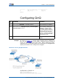
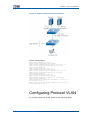
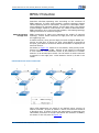
1
ZXR10 8900 Series 10 Gigabit Routing Switch User Manual (Ethernet Switching Volume) Version 2.8.02.C ZTE CORPORATION NO. 55, Hi-tech Road South, ShenZhen, P.R.China Postcode: 518057 Tel: (86) 755 26771900 Fax: (86) 755 26770801 URL: http://ensupport.zte.com.cn E-mail: [email protected] LEGAL INFORMATION Copyright © 2010 ZTE CORPORATION. The contents of this document are protected by copyright laws and international treaties. Any reproduction or distribution of this document or any portion of this document, in any form by any means, without the prior written consent of ZTE CORPORATION is prohibited. Additionally, the contents of this document are protected by contractual confidentiality obligations. All company, brand and product names are trade or service marks, or registered trade or service marks, of ZTE CORPORATION or of their respective owners. This document is provided “as is”, and all express, implied, or statutory warranties, representations or conditions are disclaimed, including without limitation any implied warranty of merchantability, fitness for a particular purpose, title or non-infringement. ZTE CORPORATION and its licensors shall not be liable for damages resulting from the use of or reliance on the information contained herein. ZTE CORPORATION or its licensors may have current or pending intellectual property rights or applications covering the subject matter of this document. Except as expressly provided in any written license between ZTE CORPORATION and its licensee, the user of this document shall not acquire any license to the subject matter herein. ZTE CORPORATION reserves the right to upgrade or make technical change to this product without further notice. Users may visit ZTE technical support website http://ensupport.zte.com.cn to inquire related information. The ultimate right to interpret this product resides in ZTE CORPORATION. Revision History Revision No. Revision Date Revision Reason R1.3 20100205 Edition update Serial Number: sjzl20093838 Contents About This Manual............................................. I Safety Instruction .............................................1 Safety Instruction........................................................... 1 Safety Signs .................................................................. 1 VLAN Configuration ...........................................3 VLAN Overview .............................................................. 3 VLAN Type ................................................................. 4 VLAN Tag................................................................... 4 VLAN Link Type .......................................................... 5 Default VLAN ............................................................. 5 PVLAN....................................................................... 5 QinQ......................................................................... 6 Subnet VLAN ............................................................. 7 Protocol VLAN ............................................................ 7 VLAN Translation ........................................................ 7 Enhanced VLAN Translation .......................................... 8 SuperVLAN ................................................................ 8 SVLAN ...................................................................... 8 Configuring VLAN ..........................................................11 Creating VLAN...........................................................11 Setting VLAN Link Type on Interface.............................12 Adding VLAN Member Port ..........................................13 Setting Port Native VLAN ............................................13 Setting Port VLAN Filtering..........................................14 Setting Port Fame Type Filtering ..................................14 Creating VLAN L3 Interface .........................................15 Binding dpi-template..................................................15 VLAN Configuration Example .......................................15 Configuring PVLAN.........................................................16 Configuring QinQ ...........................................................17 Configuring Subnet VLAN................................................18 Confidential and Proprietary Information of ZTE CORPORATION I ZXR10 8900 Series User Manual (Ethernet Switching Volume) Configuring Protocol VLAN ..............................................19 Configuring VLAN Translation ..........................................20 Configuring Enhanced VLAN Translation ............................21 Configuring SuperVLAN ..................................................22 Configuring SVLAN ........................................................25 VLAN Maintenance and Diagnosis.....................................29 STP Configuration............................................ 31 STP Overview ...............................................................31 SSTP Mode ...............................................................31 RSTP Mode ...............................................................32 MSTP Mode...............................................................32 BPDU Protection ........................................................34 Configuring STP ............................................................38 Enabling STP.............................................................38 Configuring STP Mode ................................................38 Configuring STP Parameters ........................................39 Creating an Instance..................................................40 Configuring MST Configuration Name and Version ..........40 Configuring Switch Priority ..........................................41 Configuring STP Protocol Transparent Transmission ID ...................................................................41 Configuring BPDU Protection ...........................................42 Configuring Edge Port BPDU Protection .........................42 Configuring Port Loopback Protection ...........................42 Configuring Port Root Protection ..................................43 STP Configuration Example .............................................43 STP Maintenance and Diagnosis.......................................45 MAC Table Operation ....................................... 47 MAC Address Table Overview...........................................47 Composition and Meaning of MAC Address Table ............47 MAC Address Categories .............................................48 MAC Address Table Creation and Deletion .....................49 Configuring MAC Table ...................................................50 Configuring MAC Address Aging Time ...........................50 Burning MAC Address .................................................50 Binding MAC Address .................................................51 Configuring Port MAC Address Learning ........................51 Limiting Number of MAC Addresses ..............................52 Configuring Port MAC Address Learning Protection .........52 Configuring MAC Address Filtration...............................53 II Confidential and Proprietary Information of ZTE CORPORATION Configuring 256K Mode ..............................................54 Viewing MAC Address Table.........................................54 MAC Address Table Configuration Example ........................55 ESM Configuration ........................................... 57 ESM Overview ...............................................................57 Configuring ESM............................................................57 Initializing ESM .........................................................57 Configuring ESM Mode ...............................................58 ESM Configuration Example ............................................58 ESM Maintenance and Diagnosis ......................................58 Link Aggregation Configuration ....................... 59 Link Aggregation Overview .............................................59 Configuring Link Aggregation ..........................................60 Link Aggregation Configuration Example ...........................61 Link Aggregation Maintenance and Diagnosis.....................62 IGMP Snooping Configuration.......................... 65 IGMP Snooping Overview................................................65 Multicast Group Join...................................................66 Multicast Group Leave ................................................66 Fast Leave ................................................................67 Configuring IGMP Snooping.............................................67 Enabling IGMP Snooping Function ................................67 Configuring IGMP Snooping ssm-mapping .....................68 Configuring Proxy Query Facility ..................................68 Restricting Multicast Group .........................................69 Configuring Static IGMP Snooping ................................69 Modifying IGMP Snooping Time Parameters ...................70 Configuring Master/Slave Router Interface ....................70 IGMP Snooping Configuration Example .............................71 IGMP Snooping Maintenance and Diagnosis .......................72 Link Protection Configuration .......................... 75 ZESR Configuration........................................................75 ZESR Overview .........................................................75 Configuring ZESR ......................................................76 ZESR Configuration Example .......................................77 ZESS Configuration........................................................79 ZESS Overview .........................................................79 Configuring ZESS ......................................................80 Dual-Uplink Protection....................................................80 Confidential and Proprietary Information of ZTE CORPORATION III ZXR10 8900 Series User Manual (Ethernet Switching Volume) Dual-Uplink Protection Overview ..................................80 Dual-Uplink Protection Configuration Example ...............81 Ethernet OAM Configuration ............................ 85 Configuring 802.3ah ......................................................85 802.3ah Overview .....................................................85 Remote Discovery .............................................86 Remote Loopback..............................................86 Link Monitor .....................................................86 Configuring 802.3ah ..................................................87 802.3ah Configuration Example ...................................90 Maintenance and Diagnosis of 802.3ah .........................91 Configuring CFM ............................................................93 CFM Overview ...........................................................93 Configuring CFM ........................................................95 OAM Link Control Event Configuration Example............ 102 CFM Proxy Card Function Illustration .......................... 103 CFM Configuration Example....................................... 104 CFM Maintenance and Diagnosis ................................ 107 EPON OLT Configuration ................................ 109 EPON OLT Overview ..................................................... 109 Configuring EPON OLT .................................................. 111 Configuring OLT Interface ........................................ 111 Configuring EPON Global Parameters .......................... 112 Configuring ONU Local Management........................... 116 Configuring OLT Optical Line Protection....................... 117 Configuring QoS ...................................................... 118 Configuring OLT Alarm ............................................. 119 Configuring ONU Remote Management ....................... 120 EPON OLT Configuration Example................................... 125 EPON OLT Maintenance and Diagnosis ............................ 127 UDLD Configuration ....................................... 133 UDLD Overview ........................................................... 133 Configuring UDLD ........................................................ 135 UDLD Configuration Example......................................... 136 Configuring One-command for Collection Function ........................................................ 137 One-command for Collection Function Overview............... 137 Introduction to Running Environment of One-command Collection Function .............................................. 137 IV Confidential and Proprietary Information of ZTE CORPORATION Basic Configuration of One-command for Collection Function ............................................................. 138 Introduction to One-command for Collecting Information ................................................... 138 Introduction to One-command for Collecting Fault Diagnosis Information ...................................... 139 Introduction to One-command for Configuring ............. 140 Command of Viewing One-command for Configuring..................................................... 142 Figures .......................................................... 145 Glossary ........................................................ 147 Confidential and Proprietary Information of ZTE CORPORATION V ZXR10 8900 Series User Manual (Ethernet Switching Volume) This page is intentionally blank. VI Confidential and Proprietary Information of ZTE CORPORATION About This Manual Purpose Intended Audience What Is in This Manual This manual is ZXR10 8900 Series (V2.8.02.C) 10 Gigabit Routing Switch User Manual (Ethernet Switching Volume) and applies to ZXR10 8902/8905/8908/8912 10 Gigabit routing switch. This manual is intended for the following engineers: � On-site maintenance engineers � Network monitoring engineers � System maintenance engineers This manual contains the following contents: Chapter Overview Chapter 1 Safety Instruction Describes safety instructions and signs used in this manual. Chapter 2 VLAN Configuration This chapter describes basic concept, configuration and configuration example of VLAN, PVLAN, QinQ, Subnet VLAN, Protocol VLAN, VLAN translation, SuperVLAN and SVLAN. Chapter 3 STP Configuration This chapter describes basic concept, configuration and configuration example of STP and BPDU protection. Chapter 4 MAC Table Operation This chapter describes basic concept and related operations of MAC address table. Chapter 5 ESM Configuration This chapter describes basic concept, configuration and configuration example of ESM. Chapter 6 Link Aggregation Configuration This chapter describes basic concept, configuration and configuration example of link aggregation. Chapter 7 IGMP Snooping Configuration This chapter describes basic concept, configuration and configuration example of IGMP Snooping. Chapter 8 Link Protection Configuration This chapter describes basic concept, configuration and configuration example of ZESR and ZESS. Chapter 9 Ethernet OAM Configuration This chapter describes basic concept, configuration and configuration example of Ethernet OAM. Chapter 10 EPON OLT Configuration This chapter describes basic concept, configuration and configuration example of EPON OLT. Confidential and Proprietary Information of ZTE CORPORATION I ZXR10 8900 Series User Manual (Ethernet Switching Volume) Related Documentation II Chapter Overview Chapter 11 UDLD Configuration This chapter describes basic concept, configuration and configuration example of UDLD. Chapter 12 Configuring One-command for Collection Function This chapter describes One-command for Collection Function. The following documentation is related to this manual: � ZXR10 8900 Series (V2.8.02.C) 10 Gigabit Routing Switch Hardware Installation Manual � ZXR10 8900 Series (V2.8.02.C) 10 Gigabit Routing Switch Hardware Manual � ZXR10 8900 Series (V2.8.02.C) 10 Gigabit Routing Switch User Manual (Basic Configuration) � ZXR10 8900 Series (V2.8.02.C) 10 Gigabit Routing Switch User Manual (Ethernet Switching) � ZXR10 8900 Series (V2.8.02.C) 10 Gigabit Routing Switch User Manual (IPv4 Routing) � ZXR10 8900 Series (V2.8.02.C) 10 Gigabit Routing Switch User Manual (IPv6) � ZXR10 8900 Series (V2.8.02.C) 10 Gigabit Routing Switch User Manual (MPLS) � ZXR10 8900 Series (V2.8.02.C) 10 Gigabit Routing Switch User Manual (DPI) � ZXR10 8900 Series (V2.8.02.C) 10 Gigabit Routing Switch User Manual (Firewall) � ZXR10 8900 Series (V2.8.02.C) 10 Gigabit Routing Switch Command Reference (Index) � ZXR10 8900 Series (V2.8.02.C) 10 Gigabit Routing Switch Command Reference (Basic Configuration Volume I) � ZXR10 8900 Series (V2.8.02.C) 10 Gigabit Routing Switch Command Reference (Basic Configuration Volume II) � ZXR10 8900 Series (V2.8.02.C) 10 Gigabit Routing Switch Command Reference (Basic Configuration Volume III) � ZXR10 8900 Series (V2.8.02.C) 10 Gigabit Routing Switch Command Reference (Ethernet Switching) � ZXR10 8900 Series (V2.8.02.C) 10 Gigabit Routing Switch Command Reference (IPv4 Routing Volume I) � ZXR10 8900 Series (V2.8.02.C) 10 Gigabit Routing Switch Command Reference (IPv4 Routing Volume II) � ZXR10 8900 Series (V2.8.02.C) 10 Gigabit Routing Switch Command Reference (IPv6) � ZXR10 8900 Series (V2.8.02.C) 10 Gigabit Routing Switch Command Reference (MPLS) � ZXR10 8900 Series (V2.8.02.C) 10 Gigabit Routing Switch Command Reference (Network Management) Confidential and Proprietary Information of ZTE CORPORATION About This Manual � ZXR10 8900 Series (V2.8.02.C) 10 Gigabit Routing Switch Command Reference (QoS) � ZXR10 8900 Series (V2.8.02.C) 10 Gigabit Routing Switch Command Reference (Security) � ZXR10 8900 Series (V2.8.02.C) 10 Gigabit Routing Switch Command Reference (Voice and Video) � ZXR10 8900 Series (V2.8.02.C) 10 Gigabit Routing Switch Command Reference (Multicast) � ZXR10 8900 Series (V2.8.02.C) 10 Gigabit Routing Switch Command Reference (DPI) � ZXR10 8900 Series (V2.8.02.C) 10 Gigabit Routing Switch Command Reference (Firewall) Confidential and Proprietary Information of ZTE CORPORATION III ZXR10 8900 Series User Manual (Ethernet Switching Volume) This page is intentionally blank. IV Confidential and Proprietary Information of ZTE CORPORATION Chapter 1 Safety Instruction Table of Contents Safety Instruction............................................................... 1 Safety Signs ...................................................................... 1 Safety Instruction Only duly trained and qualified personnel can install, operate and maintain the devices. During the device installation, operation and maintenance, please abide by the local safety specifications and related operation instructions, otherwise physical injury may occur or devices may be broken. The safety precautions mentioned in this manual are only supplement of local safety specifications. The debug commands on the devices will affect the performance of the devices, which may bring serious consequences. So take care to use debug commands. Especially, the debug all command will open all debug processes, so this command must not be used on the devices with services. It is not recommended to use the debug commands when the user networks are in normal state. ZTE Corporation will assume no responsibility for consequences resulting from violation of general specifications for safety operations or of safety rules for design, production and use of the devices. Safety Signs The contents that users should pay attention to when they install, operate and maintain devices are explained in the following formats: Warning: Indicates the matters needing close attention. If this is ignored, serious injury accidents may happen or devices may be damaged. Confidential and Proprietary Information of ZTE CORPORATION 1 ZXR10 8900 Series User Manual (Ethernet Switching Volume) Caution: Indicates the matters needing attention during configuration. Note: Indicates the description, hint, tip, and so on for configuration operations. 2 Confidential and Proprietary Information of ZTE CORPORATION Chapter 2 VLAN Configuration Table of Contents VLAN Overview .................................................................. 3 Configuring VLAN ..............................................................11 Configuring PVLAN.............................................................16 Configuring QinQ ...............................................................17 Configuring Subnet VLAN....................................................18 Configuring Protocol VLAN ..................................................19 Configuring VLAN Translation ..............................................20 Configuring Enhanced VLAN Translation ................................21 Configuring SuperVLAN ......................................................22 Configuring SVLAN ............................................................25 VLAN Maintenance and Diagnosis.........................................29 VLAN Overview Virtual Local Area Network (VLAN) is a technology that divides a physical network into multiple logical (virtual) LAN. Every VLAN has a VLAN identifier (VID). Taking advantage of VLAN technology, network administrators can divide the users in the same physical LAN into different broadcast domains (one broadcast domain is one VLAN). This ensures that the users with the same demands belong to same broadcast domain and users with different demands belong to different broadcast domain. Every VLAN is like an independent logical LAN, having the same attributes with physical LAN. All broadcast and unicast traffic in the same VLAN are restricted to the VLAN instead of being forwarded to other VLAN. Communication between devices belonging to different VLAN is forwarded by the Layer 3 routers. VLAN has the following features: � Reducing broadcast traffic in the network � Enhancing network security � Simplifying network management and control Confidential and Proprietary Information of ZTE CORPORATION 3 ZXR10 8900 Series User Manual (Ethernet Switching Volume) VLAN Type VLAN type is determined by the method dividing a received frame to a specific VLAN. ZXR10 8900 series switch supports port-based VLAN, which is the most simple and effective method. It assigns ports of switching equipment to different VLANs; consequently, the traffic received from the port belongs to the VLAN connected to the port. For example, if port 1, port 2 and port 3 belong to the same VLAN, and other ports belong to other VLANs, frame received by port 1 can be transmitted over port 2 and port 3 exclusively. If a user in VLAN moves to a new place, it does not belong to the old VLAN unless VLAN is reconfigured. VLAN Tag Multiple VLAN services can be transmitted in one link if the VLAN that the frame resides in can be presented in a certain method when frame is transmitting in the network. IEEE 802.1Q implements the function by inserting a VLAN tag into Ethernet frame structure. VLAN tag is 4-byte long, in Ethernet frame, its location is behind source MAC address, and before length/type segment. Format of VLAN tag is shown in Figure 1. FIGURE 1 FORMAT OF VLAN TAG VLAN tag is most frequently applied in the case of cross-switch creation of VLAN; here the connection between switches is called Trunk. Cross-multiple-switch VLAN can be created through one or more trunks after applying tag. When the port connected to the switch receives a tagged frame, it can judge which VLAN the frame belongs to according to VLAN tag. Each 802.1Q port is allocated with a default VLAN ID, which is called PVID. When the port receives untagged frame, the frame is considered to belong to port default VLAN, and forwarded in the VLAN. ZXR10 8900 series switch supports IEEE 802.1Q standard tag. 4 Confidential and Proprietary Information of ZTE CORPORATION Chapter 2 VLAN Configuration VLAN Link Type Ports on ZXR10 8900 series switch support the following types of VLAN links. � Access link Access link is used to connect the devices (for example, workstation) that cannot identify VLAN tag to VLAN switch port. It only transmits untagged VLAN frame and is associated with only one VLAN. � Trunk link Trunk link connects two devices that can identify VLAN tag and transmits multiple VLAN services. It only transmits tagged VLAN frame and can bear multiple VLANs. Most popular trunk link is the one which connects two VLAN switches. � Hybrid link Hybrid link can transmit tagged and untagged frames. However, for a specific VLAN, all frames transmitted by the hybrid link must be of same type. Default VLAN ZXR10 8900 series switch initially has a default VLAN with the following features: � VLAN ID of default VLAN is 1. � Name of default VLAN is VLAN0001. � Default VLAN contains all ports. � All ports of default VLAN is untagged by default. PVLAN To isolate messages of users for better network security, traditional solution is used to assign a VLAN to each user. Limitations of this method are described as follows: � Maximum number of VLANs supported by IEEE 802.1Q standard is 4094 and the number of users is limited; consequently, it goes against network expansion. � Each VLAN corresponds to one IP subnet, so a large quantity of subnets are divided is a waste of IP addresses. � Planning and management of a large quantity of VLANs and IP subnets complicates network management. New technology Private VLAN (PVLAN) solves all the problems. Function PVLAN classifies ports in VLAN into two categories: Isolate port that connects with users, and Promiscuous port that connects to Confidential and Proprietary Information of ZTE CORPORATION 5 ZXR10 8900 Series User Manual (Ethernet Switching Volume) router. Isolate port can communicate with Promiscuous port only. Communication between Isolate ports is disabled. So, ports in the same VLAN are isolated, users can only communicate with default gateway. This ensures the network security. QinQ QinQ is a tunneling protocol, based on IEEE 802.1Q encapsulation, which is also called VLAN stack. QinQ technology is to add a VLAN tag (outer tag) outside old VLAN tag (inner tag). Outer tag can shield the inner tag. QinQ requires no support from protocol, by which L2VPN is realized. It is particularly suitable for the small LAN with layer3 switch as the backbone. Typical networking or QinQ technology is shown in Figure 2. Port connecting user network is called customer port and the port connecting SP network is called uplink port. Edge access device of SP network is called Provider Edge (PE). FIGURE 2 TYPICAL QINQ NETWORK User network is accessed to PE through Trunk VLAN mode. Uplink ports in Service Provider (SP) network are symmetrically connected through Trunk VLAN mode. When message reaches customer port of switch A from user network 1, no matter the message is tagged or untagged, switch A inserts outer tag (VLAN ID is 10) forcibly. In the SP network, the message transmits along VLAN 10 ports until it reaches switch B. Switch B finds that the port connecting user network 2 is customer port, so it peels off the outer tag according to traditional 802.1Q. It resumes the original message and transmits it to user network 2. 6 Confidential and Proprietary Information of ZTE CORPORATION Chapter 2 VLAN Configuration As a result, user network 1 and 2 can perform transparent transmission through SP network. User network can define its own private network VLAN ID that does not have a conflict with SP network VLAN ID. Subnet VLAN VLAN based on subnet is applied to the VLAN network of Layer 2, and implements flexible configuration of data frame. VLAN based on subnet transmits the frame to corresponding VLAN according to the source IP address of the data frame. VLAN that is composed according to source IP address makes it possible for users in different network section to transmit frames through multi VLANs. But the member identity of the VLAN is not changed. Subnet VLAN spaces the data frames of different source IP addresses out, so users get the data belonging to the same network sects. PRI to transmit subnet VLAN of UNTAG frame is higher than protocol VLAN and PVID. TAG frame transmits data in TAG mode, so its PRI is higher than subnet VLAN. Protocol VLAN VLAN based on protocol is flexible and applicable to Layer 3. A VLAN that is based on protocol is plotted according to the encapsulation protocol in network layer of the data packet. Packets of same label are in the same protocol VLAN. VLAN that is composed according to the protocols in network layer makes it possible for the broadcasting region to cover multi switches. Users can move freely within the network, and the member identity of the VLAN is not changed. When the user’s physical position is changed then there is no need to configure the VLAN to which the user belongs; instead it plots the VLAN according to the protocol type. It does not require additional label to identify the VLAN. In this way, the communication quantity is reduced. Protocol VLAN defaults “enable” on physical interfaces. It plots the VLAN according to the label in the data packets. It spaces packets of different labels out, so the user gets the data’s in the same VLAN. VLAN Translation VLAN translation is also called VLAN mapping. It allows the VLAN IDs of different Ethernet switches used to access to boundary to set as superposition. It modifies the iterative VLAN IDs of different switches to different VLAN IDs through the VLAN translation function, and transmits them in uplink interfaces. So it spaces users out in core switches of Layer 2. It predigests the configurations of switches accessing to boundary. Confidential and Proprietary Information of ZTE CORPORATION 7 ZXR10 8900 Series User Manual (Ethernet Switching Volume) Enhanced VLAN Translation The function and application of enhanced VLAN translation are similar to those of VLAN translation. The seven functions added on the basis of VLAN translation are as follows: � Import single layer tag, add outer tag according to policy. � Import single layer tag, modify inner tag and add outer tag according to policy . � Import double-layer tag, delete outer tag according to policy. � Import double-layer tag, delete outer tag and modify inner tag according to policy. � Import double-layer tag, modify outer tag according to policy. � Import double-layer tag, modify inner tag according to policy. � Import double-layer tag, modify inner and outer tags according to policy. Of which policy means: Modify single layer tag according to access port and VLAN tag. Modify double-layer tag according to access port and inner and outer tags at the same time. ZZXR10 8902/8905/8908/8912 supports 4096 enhanced VLAN translations when whole device line cards are H boards. SuperVLAN Traditional ISP network assigns one IP subnet to each user. Three IP addresses are occupied when one subnet is assigned, which respectively serve as subnet number, broadcast address and default gateway. A large quantity of unassigned IP addresses in the user subnets cannot be assigned to other users. This method wastes number of IP address. SuperVLAN solves the problem effectively. It can convert multiple VLANs (called subvlan) into a SuperVLAN. All the subvlans use the same IP subnet and default gateway. Taking advantage of SuperVLAN technology, ISP needs to assign one IP subnet for SuperVLAN and create one sub-VLAN for each user. All sub-VLANs can assign IP addresses in SuperVLAN subnet flexibly and use SuperVLAN default gateway. Every sub-VLAN is an independent broadcast domain, ensuring isolation between different users. Communication between sub-VLANs is routed through SuperVLAN. SVLAN Selective VLAN (SVLAN) is a kind of VLAN tunnel techniques. SVLAN technology is to add a VLAN tag (outer tag) outside old 8 Confidential and Proprietary Information of ZTE CORPORATION Chapter 2 VLAN Configuration VLAN tag (inner tag). Outer tag can shield the inner tag. When a message arrives at PE after transparent transmission through service provider network, outer tag is removed. This contributes a transparent transmission service of point to multi-point VPN and provides a simple L2VPN tunnel for customers. The double decks of tags extend the number of VLANs effectively. It is up to 4094*4094. Outer VLAN is called Service Provider VLAN (SPVLAN), and inner VLAN is called customer VLAN (CVLAN). QinQ technology only adds outer tags to messages that arrive at a port. This limits the network building flexibility dramatically. While SVLAN technology adds different outer tags to messages that are received at the same port according to customer demands. Some service flows require messages not to be disturbed when messages pass by switches. That is, tag number and value are not changed. SVLAN technology supports transparent transmission VLAN services. SVLAN technology also supports 802.1P cos priority mapping between outer tag and inner tag. SVLAN Functions SVLAN has the following functions. � SVLAN adds different outer tags to different inner tags. This is described with the following steps. i. SVLAN maps inner tag priority to outer tag, as shown in Figure 3. FIGURE 3 PRIORITY MAPPING ii. Fixed priorities of outer layers are as shown in Figure 4. FIGURE 4 FIXING PRIORITIES OF OUTER TAGS Confidential and Proprietary Information of ZTE CORPORATION 9 ZXR10 8900 Series User Manual (Ethernet Switching Volume) iii. SVLAN does not care outer layer priority, as shown in Figure 5. FIGURE 5 MARKING � OUTER TAG ONLY SVLAN switches messages that are with the same outer tag but different ports to a same egress, as shown in Figure 6. FIGURE 6 SWITCHING � AN TO THE SAME EGRESS SVLAN does not add outer tag to messages that are with designated inner tags. That is, SVLAN transmits such messages transparently, as shown in Figure 7. FIGURE 7 SVLAN TRANSPARENT TRANSMISSION 10 Confidential and Proprietary Information of ZTE CORPORATION Chapter 2 VLAN Configuration � Figure 8 shows a more complex situation. FIGURE 8 A MORE COMPLEX SITUATION Configuring VLAN Creating VLAN 1. Creating specified VLAN and entering VLAN configuration mode. Step Command Function 1 ZXR10(config)#vlan <vlan-id> Only VLAN1 is available on switch. With this command, other VLANs can be created. 2 ZXR10(config-vlan)#name <vlan-name> This sets alias for VLAN. In some commands, alias can be used to replace VLAN number. VLAN alias can be group name, department, area and so on, used to distinguish VLANs. VLAN alias is composed of VLAN+VLAN ID by default, where VLAN ID contains 4 digits and uses 0 to fill the blank ahead. For example, as for vlan whose id is 4, the alias id vlan0004 by default. 2. Creating VLANs in batch. Confidential and Proprietary Information of ZTE CORPORATION 11 ZXR10 8900 Series User Manual (Ethernet Switching Volume) Step Command Function 1 ZXR10#vlan database This enters VLAN database. 2 ZXR10(vlan)#vlan <vlan-list> This creates VLANs in database in batch. 3 ZXR10(config-vlan)#name <vlan-name> This sets alias for VLAN. In some commands, alias can be used to replace VLAN number. VLAN alias can be group name, department, area and so on, used to distinguish VLANs. VLAN alias is composed of VLAN+VLAN ID by default, where VLAN ID contains 4 digits and uses 0 to fill the blank ahead. For example, as for vlan whose id is 4, the alias id vlan0004 by default. Setting VLAN Link Type on Interface Step Command Function 1 ZXR10(config)#interface < interface-name> This accesses L2 interface on switch. 2 ZXR10(config-if)#switchport mode {access|trunk This sets VLAN link type of the Ethernet interface. |hybrid} There are three VLAN link types on Ethernet interface: access mode, trunk mode and hybrid mode. Access mode is the default configuration. � The port connecting with access link can only belong to one VLAN. It shall be untagged and is used to connect host in usual cases. � The port connecting with trunk link can belong to multiple vlans. It must be tagged, can receive and send packets of multiple vlans, and is used to connect two switches in usual cases. � The port connecting with hybrid link can belong to multiple vlans. User can customize whether to attach tag to the packet on the port. It can receive and send packets of multiple vlans and can be used to connect two switches or to connect pc. The difference between hybrid port and trunk port lies in that hybrid port can send both tagged and untagged frames, while packets sent from trunk port are untagged only when they are sent from default vlan. 12 Confidential and Proprietary Information of ZTE CORPORATION Chapter 2 VLAN Configuration Adding VLAN Member Port Access port can join only one vlan, while trunk port and hybrid port can join multiple vlans. � Joining access port to designated vlan. Step Command Function 1 ZXR10(config)#interface < interface-name> This accesses L2 interface on switch. 2 ZXR10(config-if)#switchport access vlan {<vlan-id>|<vlan-name>} This sets the vlan where port belongs to. � Joining trunk port to designated vlan. Step Command Function 1 ZXR10(config)#interface < interface-name> This accesses L2 interface on switch. 2 ZXR10(config-if)#switchport trunk vlan <vlan-list> This sets the vlan where port belongs to. � Joining Hybrid port to designated vlan. Step Command Function 1 ZXR10(config)#interface < interface-name> This accesses L2 interface on switch. 2 ZXR10(config-if)#switchport hybrid vlan This sets the vlan where port belongs to and specifies whether to tag packets sent from these vlans. <vlan-list>[tag|untag] � Adding VLAN member ports in batch. Command Function ZXR10(config-vlan)#switchport {pvid|tag|untag}<por This adds vlan member ports in batch in vlan configuration mode. t-list> Setting Port Native VLAN Access port only belongs to one VLAN, so its native VLAN is that it locates and it doesn't need to set native VLAN. Confidential and Proprietary Information of ZTE CORPORATION 13 ZXR10 8900 Series User Manual (Ethernet Switching Volume) Trunk port and hybrid port belong to multiple vlans and they need to set native vlan. If native vlan is set on port, when one frame with no vlan tag is received on port, it will be forwarded to the port belonging to this native vlan. Native vlan of trunk port and hybrid port is vlan 1 by default. Step Command Function 1 ZXR10(config)#interface < interface-name> This accesses L2 interface on switch. 2 ZXR10(config-if)#switchport {trunk | hybrid} native vlan {<vlan-id>|<vlan-name>} This sets native VLAN of trunk port and hybrid port. Setting Port VLAN Filtering Step Command Function 1 ZXR10(config)#interface < interface-name> This accesses L2 interface on switch. 2 ZXR10(config-if)# ingress filtering {enable|disab This sets port VLAN filtering. VLAN ingress filtering is enabled by default. le} After enabling ingress filtering, if this ingress doesn't belong to the VLAN that frame received on the port belongs to, the frame will be dropped. Setting Port Fame Type Filtering Step Command Function 1 ZXR10(config)#interface < interface-name> This accesses L2 interface on switch. 2 ZXR10(config-if)# acceptable frame types {all|tag} This sets port fame type for filtering. This command is used to configure the type of frame that can be accepted by port. User can choose to accept all frames (including tagged frames and tagged frames) or only accept tagged frames. 14 Confidential and Proprietary Information of ZTE CORPORATION Chapter 2 VLAN Configuration Creating VLAN L3 Interface Command Function 1 ZXR10(config)#vlan <vlan-id> This creates VLAN. 2 ZXR10(config-vlan)#exit This exits VLAN configuration mode. 3 ZXR10(config)#interface vlan< vlan-id > This creates VLAN L3 interface. Command shutdown can be used to disable VLAN L3 interface and command no shutdown can be used to enable VLAN L3 interface. When all Ethernet interfaces under VLAN interface are down, vlan interface is down by default; when one or more Ethernet interfaces under one VLAN interface are up, the vlan interface is up. Binding dpi-template Step Command Function 1 ZXR10(config)#interface vlan< vlan-id > This creates VLAN L3 interface. ZXR10(config-if-vlan1)#bind dpi-template This binds related dpi-template. 2 <template-id> VLAN Configuration Example As shown in Figure 9, interfaces gei_3/1 and gei_3/2 of switch A and gei_7/1 and gei_7/2 of switch B belong to vlan 10; interfaces gei_3/4 and gei_3/5 of switch A and gei_7/4 and gei_7/5 of switch B belong to vlan 20. All of these interfaces are access port. Two switches are interconnected in trunk mode through interfaces gei_3/24 and gei_7/24. The two interfaces are trunk port. FIGURE 9 TYPICAL VLAN NETWORKING Confidential and Proprietary Information of ZTE CORPORATION 15 ZXR10 8900 Series User Manual (Ethernet Switching Volume) Configuration of Switch A: ZXR10_A(config)#vlan 10 ZXR10_A(config-vlan)#switchport pvid gei_3/1-2 ZXR10_A(config)#vlan 20 ZXR10_A(config-vlan)#switchport pvid gei_3/4-5 ZXR10_A(config)#interface gei_3/24 ZXR10_A(config-if)#switchport mode trunk ZXR10_A(config-if)#switchport trunk vlan 10 ZXR10_A(config-if)#switchport trunk vlan 20 Configuration of switch B ZXR10_B(config)#vlan 10 ZXR10_B(config-vlan)#switchport pvid gei_7/1-2 ZXR10_B(config)#vlan 20 ZXR10_B(config-vlan)#switchport pvid gei_7/4-5 ZXR10_B(config)#interface gei_7/24 ZXR10_B(config-if)#switchport mode trunk ZXR10_B(config-if)#switchport trunk vlan 10 ZXR10_B(config-if)#switchport trunk vlan 20 Configuring PVLAN To configure PVLAN, perform the following steps. Step Command Function 1 ZXR10(config)#vlan private-map session-id <id>[c This configures isolate and promiscuous port ommunity <port-list>][isolate <port-list>][promis <port-list>][vlan <vlan-list>] 2 ZXR10(config)#show vlan private-map This views PVLAN configuration information Note: ZXR10 8900 series switch supports 256 PVLAN groups. Each group can select any port to isolate from each other. At most 4 ports can be selected to be uplink port. Example Two Isolate groups are configured in the following configuration example: � Isolate group 1: gei_3/1, gei_3/2, fei_7/4 and fei_7/5 are isolate ports; gei_5/10 is Promiscuous port. � Isolate group 2: gei_3/7, gei_3/8, fei_7/10 and fei_7/11 are isolate ports; gei_5/12 is Promiscuous port. Detailed configuration is shown below. ZXR10(config)#vlan private-map session-id 1 isolate gei_3/1-2,fei_7/4-5 promis gei_5/10 ZXR10(config)#vlan private-map session-id 2 isolate gei_3/7-8,fei_7/10-11 promis gei_5/12 ZXR10(config)#show vlan private-map Session_id Isolate_Ports Promis_Ports 16 Confidential and Proprietary Information of ZTE CORPORATION Chapter 2 VLAN Configuration ---------1 2 ZXR10# -------------------- ------------------gei_3/1-2,fei_7/4-5, gei_5/10 gei_3/7-8, gei_5/12 Configuring QinQ Step Command Function 1 ZXR10(config)#interface < interface-name> This accesses L2 interface. 2 ZXR10(config-if)#switchport qinq {normal|uplink This configure QinQ port attribute, where normal indicates no QinQ. Port is in normal state by default. Uplink indicates the port is connected with upstream carrier. Customer indicates the port is connected with downstream user. |customer|tpid <tpid>} 3 ZXR10(config-if)#show qinq Example This shows QinQ configuration result. As shown in Figure 10, assume that customer port of switch A is gei_3/1 and uplink port is gei_3/24; customer port of switch B is gei_7/1 and uplink port is gei_7/24. When configuring QinQ, customer port of SPVLAN needs to be configured to untagged and uplink port needs to be configured to tagged. FIGURE 10 TYPICAL QINQ NETWORKING Configuration of Switch A: ZXR10_A(config)#vlan 10 ZXR10_A(config)#interface gei_3/1 ZXR10_A(config-if)#switchport qinq customer Confidential and Proprietary Information of ZTE CORPORATION 17 ZXR10 8900 Series User Manual (Ethernet Switching Volume) ZXR10_A(config-if)#switchport access vlan 10 ZXR10_A(config)#interface gei_3/24 ZXR10_A(config-if)#switchport qinq uplink ZXR10_A(config-if)#switchport mode trunk ZXR10_A(config-if)#switchport trunk vlan 10 Configuration of switch B ZXR10_B(config)#vlan 10 ZXR10_B(config)#interface gei_7/1 ZXR10_B(config-if)#switchport qinq customer ZXR10_B(config-if)#switchport access vlan 10 ZXR10_B(config)#interface gei_7/24 ZXR10_B(config-if)#switchport qinq uplink ZXR10_B(config-if)#switchport mode trunk ZXR10_B(config-if)#switchport trunk vlan 10 Configuring Subnet VLAN To configure subnet VLAN, perform the following steps. Step Command Function 1 ZXR10(config)#vlan subnet-map session-no<session This configures subnet VLAN function -no><ipaddr><mask> vlan {<vlanid><name>} 2 ZXR10(config)#show vlan subnet-map This views subnet VLAN configuration information Note: ZXR10 8900 series switch supports 128 subnet VLANs, and can process data frames of 128 types of source IP network sects. Example 18 Figure 11 shows configuration of subnet VLAN data on the switch, VLAN20 and VLAN30. Interface fei_1/1 belongs to VLAN20; interface fei_1/2 belongs to VLAN30. Interface fei_1/10 belongs to VLAN20 and VLAN30. PVIDs of fei_1/1, fei_1/2 and fei_1/10 are different. PCs of source IP address 20.20.20.0/24 network sect are accessible to server1, and PCs of IP address 30.30.30.1 are accessible to server2. Confidential and Proprietary Information of ZTE CORPORATION Chapter 2 VLAN Configuration FIGURE 11 SUBNET VLAN CONFIGURATION EXAMPLE Switch configuration: ZXR10(config)#interface fei_1/1 ZXR10(config-int)#switch mode hybrid ZXR10(config-int)#switchport hybrid native vlan 20 ZXR10(config-int)#switch hybrid vlan 20 untag ZXR10(config-int)#exit ZXR10(config)#interface fei_1/2 ZXR10(config-int)#switch mode hybrid ZXR10(config-int)#switchport hybrid native vlan 30 ZXR10(config-int)#switch hybrid vlan 30 untag ZXR10(config-int)#exit ZXR10(config)#interface fei_1/10 ZXR10(config-int)#switch mode hybrid ZXR10(config-int)#switch hybrid vlan 20,30 untag ZXR10(config-int)#exit ZXR10(config)#vlan subnet-map session-no 1 20.20.20.0 255.255.255.0 vlan 20 ZXR10(config)#vlan subnet-map session-no 2 30.30.30.1 255.255.255.255 vlan 3 Configuring Protocol VLAN To configure protocol VLAN, perform the following steps. Confidential and Proprietary Information of ZTE CORPORATION 19 ZXR10 8900 Series User Manual (Ethernet Switching Volume) Step Command Function 1 ZXR10(config)#vlan protocol-map session-no This configures protocol VLAN function <session-no>{ethernet2| llc| snap}<0xHHHH> vlan {<vlanId>|<name>} 2 3 ZXR10(config)#interface <interface-name> This enters interface configuration mode ZXR10(config-if)#vlan protocol-map {enable | This enables or disables a protocol VLAN disable} 4 ZXR10(config)#show vlan protocol-map This displays protocol VLAN configuration information Note: ZXR10 8900 series switch supports up to 16 protocol VLANs. Example There are two data packets of different protocols in a client interface fei_1/1 on a switch, 0X800 and 0X8100. It observes the two packets respectively in another two interfaces fei_1/2 and fei_1/3. Configuration on the switch: ZXR10(config)#vlan protocol-map session-no 1 ethernet2 0x800 vlan 10 ZXR10(config)#vlan protocol-map session-no 2 ethernet2 0x7000 vlan 20 ZXR10(config)#interface fei_1/1 ZXR10(config-if)#switchport mode trunk ZXR10(config-if)#switchport trunk vlan 10,20 ZXR10(config)#exit ZXR10(config)#interface fei_1/2 ZXR10(config-if)#switchport mode trunk ZXR10(config-if)#switchport trunk vlan 10 ZXR10(config)#exit ZXR10(config)#interface fei_1/3 ZXR10(config-if)#switchport mode trunk ZXR10(config-if)#switchport trunk vlan 20 ZXR10(config)#exit Configuring VLAN Translation To configure VLAN translation, perform the following steps. 20 Confidential and Proprietary Information of ZTE CORPORATION Chapter 2 VLAN Configuration Step Command Function 1 ZXR10(config)#vlan translate session-no This configures VLAN translation function <session_id>{ingress-port | egress-port}<interf ace-name> ingress-vlan <vlan-list> egress-vlan <vlanId>[uplink-port <interface-name>] 2 ZXR10(config)#show vlan translate [session-no <session_id>] This displays VLAN translation configuration information Note: ZXR10 8900 series switch supports 1024 VLAN translations. VLAN translation function is only supported on gigabit boards. Example There is a data packet VLAN 100 in a client interface of a switch. It is necessary to modify the data packet to fei_2/1 to VLAN 200. Configuration on the switch: ZXR10(config)#vlan translate session-no 1 ingress-port gei_1/1 ingress-vlan 100 egress-vlan 200 ZXR10(config)#int gei_1/1 ZXR10(config-if)#ingress filtering disable ZXR10(config-if)#switchport access vlan 100 ZXR10(config)#exit ZXR10(config)#int fei_2/1 ZXR10(config-if)#switchport access vlan 200 ZXR10(config-if)#exit Configuring Enhanced VLAN Translation Command Function ZXR10(config)#vlan translate enhanced This configures enhanced VLAN translation. session-no <session_id>{ingress-port <interface-name>|egress-port<inter face-name>}{ingress-vlan<vlanId> egress-invlan <vlanId> egress-outvlan <vlanId>|ingress-invlan <vlanId> ingress-outvlan <vlanId> egress-invlan <vlanId> egress-outvlan {<vlanId>|unt ag}} ZXR10#show vlan enhanced-trans Example This shows enhanced VLAN translation configuration result. Create session 1, configure entry enhanced VLAN translation, translate single tag message with vlan 10 imported from gei_1/1 into vlan 100 and add outer tag 200. Confidential and Proprietary Information of ZTE CORPORATION 21 ZXR10 8900 Series User Manual (Ethernet Switching Volume) Create session 2, configure egress enhanced VLAN translation, translate single tag message with vlan 10 imported from gei_1/1 into vlan 100 and add outer tag 200. ZXR10(config)#vlan translate enhanced gei_1/1 ingress-vlan 10 egress-invlan ZXR10(config)#vlan translate enhanced gei_1/1 ingress-vlan 10 egress-invlan session-no 1 ingress-port 100 egress-outvlan 200 session-no 3 egress-port 100 egress-outvlan 200 Create session 3, configure entry enhanced VLAN translation, translate double-layer tag message with inner VLAN 10 and outer VLAN 20 imported by gei_1/1 into inner VLAN 100 and outer VLAN 200 . Create session 4, configure egress enhanced VLAN translation, translate double-layer tag message with inner VLAN 10 and outer VLAN 20 imported by gei_1/1 into inner VLAN 100 and outer VLAN 200 . ZXR10(config)#vlan translate enhanced session-no 3 ingress-port gei_1/1 ingress-invlan 10 ingress-outvlan 20 egress-invlan 100 egress-outvlan 200 ZXR10(config)#vlan translate enhanced session-no 3 egress-port gei_1/1 ingress-invlan 10 ingress-outvlan 20 egress-invlan 100 egress-outvlan 200 When realizing the above seven functions by command configuration, for imported single layer tag message, if only add outer tag, configure the value of egress-invlan same as that of ingress-vlan. For imported double-layer tag message, if only need to modify one of them, configure another translated tag same as the vlaue before translation. If need to delete outer tag, set the value of egress-outvlan as untag. Configuring SuperVLAN Step Command Function 1 ZXR10(config)#interface supervlan <supervlan-id> This creates SuperVLAN and supervlan-id ranges from 1 to 255. 2 ZXR10(config)#vlan <vlan-id> This enters VLAN configuration mode. 3 ZXR10(config-vlan)#supervlan <supervlan-id> This adds sub-vlan (Utmost 4094 subvlans can be bound to one SuperVLAN. The sub-vlan that has been configured with l3 interface cannot be bound to SuperVLAN.) 4 ZXR10(config)#interface supervlan <supervlan-id> This enters Supervlan interface configuration mode and supervlan-id ranges from 1 to 255. 22 Confidential and Proprietary Information of ZTE CORPORATION Chapter 2 VLAN Configuration Step Command Function 5 ZXR10(config-if)#inter-subvlan-routing This enables/disables routing function among vlans. This function is enabled by default. {enable|disable} 6 ZXR10(config-if)#arp-broadcast {enable|disable} This enables/disables ARP broadcast function. This function is disabled by default. 7 ZXR10(config)#vlan <vlan-id> This enters VLAN configuration mode. 8 ZXR10(config-vlan)#ip supervlan pool <ip address begin><ip address end> This creates IP address pool for SuperVLAN. 9 ZXR10(config)#interface supervlan <supervlan-id> This enters SuperVLAN interface configuration mode. 10 ZXR10(config-if)#ip-pool-filter {enable|disable} This enables/disables IP address filtering function. This function is enabled by default. 11 ZXR10(config-if)#arp-gratuitous {enable|disable} This enables/disables the function of sending free-arp message. 12 ZXR10(config-if)#arp-gratuitous subvlan <vlan-list> This sends free-arp message to specified SubVLAN. 13 ZXR10(config-if)#vrrp-advertisement send {rotation | subvlan <vlan-id>} This configures the sending mode of VRRP heartbeat message. 14 ZXR10(config)#show supervlan [{supervlan-id}] This shows configuration information of SuperVLAN. ARP broadcast function description: ARP broadcast function is disabled by default. When routing function is enabled among sub-vlans, ARP proxy function is enabled on SuperVLAN interface. If ARP broadcast function is enabled and ARP requested destination address cannot be found in local ARP table, ARP request will be broadcast. Local ARP table will be updated when receiving response. In case ARP broadcast function is disabled, ARP request will not be sent to sub-vlans. How to create IP address pool for SuperVLAN is as follows: Create the IP address pool of this SuperVLAN in the SubVLAN bound with the SuperVLAN interface. The device supports up to 4094 IP pools, the number of each IP pool is up to 255, the total number of IP addresses supported by the device is up to 64k. IP address filtering function description: When routing function is enabled among sub-vlans, ARP proxy function is enabled on SuperVLAN interface. In case IP address filtering function is enabled, SuperVLAN received ARP request will be filtered. If the source ip is beyond IP-POOL range of corresponding VLAN, the ARP request is illegal and will be dropped. Confidential and Proprietary Information of ZTE CORPORATION 23 ZXR10 8900 Series User Manual (Ethernet Switching Volume) If source IP address is legal but destination address of ARP request fails to be found in local ARP table, ARP request will be broadcast to sub-vlans and ARP table will be updated after response is received. In case IP address filtering function is enabled, view IP-POOL of which VLAN does the destination address of ARP request belongs to and send ARP request to this VLAN. Note: In case IP address filtering function is enabled, IP-POOL cannot be null. In case IP address filtering function is disabled, source IP will not be checked and it doesn't need to configure IP-POOL. How to enable/disable the function of sending free-arp message is as follows: When the function of sending free-arp is enabled, superVLAN interface will send free-arp to all SubVLANs. If the command of arp-gratuitous disable is carried out, free-arp is not sent to any subVLAN. Only in the state of arp-gratuitous disable can free-arp send to the specified subVALN. How to send free-arp message to the specified SubVLAN is as follows: This command must be carried out in the state of arp-gratuitous disable, that is, this command can be enabled only when the function of sending free-arp to any subVLAN is disabled first. Correspondingly, carry out the command of no arp-gratuitous subvlan <vlan-list> to disable sending free-arp to the specified subVLAN. If recover to the default state, that is, send free-arp to all subVLANs, carry out the command of arp-gratuitous enable. The sending mode of VRRP heartbeat message is introduced as follows: Send VRRP heartbeat message by configuring SuperVLAN to apply the specified SubVLAN or round-robin mode. In round-robin mode, SuperVLAN traverses all SubVLANs , send VRRP heartbeat message from one SubVLAN every time. The two modes avoid sending VRRP heartbeat message to all SubVLANs of SuperVLAN each time which affects system performance. Example 24 As shown in Figure 12, configure SuperVLAN on switch A and assign sub-net 10.1.1.0/24 with GW to be 10.1.1.1. Configure two sub-vlans (vlan 2 and vlan 3) on switch B and make them belong to SuperVLAN. Switch A and switch B are interconnected through Trunk ports. Confidential and Proprietary Information of ZTE CORPORATION Chapter 2 VLAN Configuration FIGURE 12 SUPERVLAN CONFIGURATION EXAMPLE Configuration of Switch A: /*Create SuperVLAN, assign subnets, and specify GW*/ ZXR10_A(config)#interface supervlan 10 ZXR10_A(config-int)#ip address 10.1.1.1 255.255.255.0 /*Join SubVLAN to SuperVLAN*/ ZXR10_A(config)#vlan 2 ZXR10_A(config-vlan)#supervlan 10 ZXR10_A(config)#vlan 3 ZXR10_A(config-vlan)#supervlan 10 /*Set vlan trunk port*/ ZXR10_A(config)#interface gei_7/10 ZXR10_A(config-int)#switch mode trunk ZXR10_A(config-int)#switch trunk vlan 2-3 Configuration of switch B: ZXR10_B(config)#interface gei_3/1 ZXR10_B(config-int)#switch access vlan 2 ZXR10_B(config)#interface gei_3/10 ZXR10_B(config-int)#switch access vlan 2 ZXR10_B(config)#interface gei_5/1 ZXR10_B(config-int)#switch access vlan 3 ZXR10_B(config)#interface gei_5/10 ZXR10_B(config-int)#switch access vlan 3 ZXR10_B(config)#interface gei_8/10 ZXR10_B(config-int)#switch mode trunk ZXR10_B(config-int)#switch trunk vlan 2-3 Configuring SVLAN To configure SVLAN function, use the following command. Confidential and Proprietary Information of ZTE CORPORATION 25 ZXR10 8900 Series User Manual (Ethernet Switching Volume) Command Function ZXR10(config)#vlan qinq session-no <session-id> cust This configures SVLAN function omer-port <port-id> uplink-port <port-id>{{in-vlan <vlan-id>{{ovlan <vlan-id>}|{untag helper-vlan <vlan-id>}}}| default-vlan-forwarding |{untag ovlan <vlan-id>[undirect]}} Note: To disable SVLAN function, use no vlan qinq {session <session -id>|all} command in global configuration mode. Example This example shows how to configure SVLAN function. The same customer port supports multiple different outer tag and transparent transmission flow. Configuration requirements are described below: � ZXR10 8908 adds outer tags to the messages with tag 10 that are received at customer port fei_1/1. Then ZXR10 8908 transmits these messages at uplink port fei_1/2. Outer tag is 997, and inner tag is 10. � ZXR10 8908 adds outer tags to the messages with tag 11 that are received at customer port fei_1/1. Then ZXR10 8908 transmits these messages at uplink port fei_1/2. Outer tag is 998, and inner tag is 11. � ZXR10 8908 transmits messages with tag 999 transparently. These messages are received at customer port fei_1/1 and transmitted at uplink port fei_1/2. Network topology is shown in Figure 13. 26 Confidential and Proprietary Information of ZTE CORPORATION Chapter 2 VLAN Configuration FIGURE 13 SVLAN CONFIGURATION EXAMPLE Configuration on ZXR10 8908: ZXR10(config)#vlan qinq session-no 1 customer-port fei_1/1 uplink-port fei_1/2 in-vlan 10 ovlan 997 ZXR10(config)#vlan qinq session-no 2 customer-port fei_1/1 uplink-port fei_1/2 in-vlan 11 ovlan 998 ZXR10(config)#vlan qinq session-no 3 customer-port fei_1/1 uplink-port fei_1/2 in-vlan 999 untag helper-vlan 4094 ZXR10(config)#interface fei_1/1 ZXR10(config-if)#negotiation auto ZXR10(config-if)#switchport mode hybrid ZXR10(config-if)#switchport hybrid vlan 999 tag ZXR10(config-if)#switchport hybrid vlan 997-998 untag ZXR10(config-if)#switchport qinq customer ZXR10(config-if)#exit ZXR10(config)#interface fei_1/2 ZXR10(config-if)#switchport mode hybrid ZXR10(config-if)#switchport hybrid vlan 997-998 tag ZXR10(config-if)#switchport hybrid vlan 999 tag ZXR10(config-if)#switchport hybrid vlan 4094 untag ZXR10(config-if)#switchport qinq uplink To configure VFP-based SVLAN, perform the following steps. Confidential and Proprietary Information of ZTE CORPORATION 27 ZXR10 8900 Series User Manual (Ethernet Switching Volume) Step Command Function 1 ZXR10(config)#vfp session <session-no> invlan This creates VFP-based SVLAN {<vlan range>| any} in <acl-number> rule <rule-id>{{ovlan <vlan id>}|{untag {global | pinpoint}}} 2 ZXR10(config)#interface <interface-name> This enters interface configuration mode 3 ZXR10(config-if)#ip access-group <acl-number> vfp This applies VFP-based SVLAN Note: VLAN Filter Processor (VFP) is a function module in switch. It implements SVLAN function based on flow categories. VFP based SVLAN configuration uses ACL to add outer tag according to flow categories. Example This example shows how to configure VFP-based SVLAN. � ZXR10 8908 adds outer tags to the messages with tag 10 and source IP 192.168.0.1 that are received at customer port fei_1/1. Then ZXR10 8908 transmits these messages at uplink port fei_1/2. Outer tag is 997, and inner tag is 10. � ZXR10 8908 adds outer tags to the messages with tag 10 and source IP 192.168.0.2 that are received at customer port fei_1/1. Then ZXR10 8908 transmits these messages at uplink port fei_1/2. Outer tag is 998, and inner tag is 10. � ZXR10 8908 adds outer tags to the messages with tag 11 that are received at customer port fei_1/1. Then 8908 transmits these messages at uplink port fei_1/2. Outer tag is 998, and inner tag is 11. � ZXR10 8908 transmits messages with tag 999 transparently. These messages are received at customer port fei_1/1 and transmitted at uplink port fei_1/2. Network topology is shown in Figure 13. Configuration on ZXR10 8908: ZXR10(config)#vfp session 1 invlan 10 in 10 rule 1 ovlan 997 ZXR10(config)#vfp session 2 invlan 10 in 10 rule 2 ovlan 998 ZXR10(config)#vfp session 3 invlan 11 in 10 rule 3 ovlan 998 ZXR10(config)#vfp session 4 invlan 999 in 10 rule 3 untag pinpoint ZXR10(config)#acl standard number 10 ZXR10(config-std-acl)#rule 1 permit 192.168.0.1 0.0.0.0 ZXR10(config-std-acl)#rule 2 permit 192.168.0.2 0.0.0.0 ZXR10(config-std-acl)#rule 3 permit any ZXR10(config)#interface fei_1/1 ZXR10(config-if)#negotiation auto ZXR10(config-if)#switchport mode hybrid ZXR10(config-if)#switchport hybrid vlan 999 tag ZXR10(config-if)#switchport hybrid vlan 997-998 untag ZXR10(config-if)#ip access-group 10 vfp ZXR10(config-if)#switchport qinq customer 28 Confidential and Proprietary Information of ZTE CORPORATION Chapter 2 VLAN Configuration ZXR10(config)#interface fei_1/2 ZXR10(config-if)#switchport mode hybrid ZXR10(config-if)#switchport hybrid vlan 997-998 tag ZXR10(config-if)#switchport hybrid vlan 999 tag ZXR10(config-if)#switchport qinq uplink To view SVLAN configuration information, use the following command. Command Function ZXR10#show vlan qinq [session <session-id>] This displays VLAN configuration information Example This example shows how to view SVLAN configuration information. ZXR10#sh vlan qinq Session Customer Uplink In_Vlan Out_Vlan Priority redirect ----------------------------------------------------1 fei_1/1 fei_1/2 1-10 20 mapping 2 fei_1/1 gei_1/2 30 0 Description of displayed fields: Field Description Session Session ID Customer Customer port Uplink Uplink port number or smartgroup number In_vlan Inner tag. Value 0 means untag Out_vlan Outer tag. Value 0 means transparent transmission priority Priority of outer tag, identifying whether to mapping QoS of outer tag VLAN Maintenance and Diagnosis To view VLAN configuration information, use the following command. Command Function ZXR10#show vlan [brief|access|trunk|hybrid|id This views VLAN configuration information <vlan-id>[ifindex]|name <vlan-name>[ifindex]] Confidential and Proprietary Information of ZTE CORPORATION 29 ZXR10 8900 Series User Manual (Ethernet Switching Volume) Note: Users can view information of all VLANs, VLAN with specified ID, and VLAN with specified name. It also can be viewed the information of the VLAN with port mode of Access, Trunk and Hybrid. Example This example displays configuration information of all VLANs. ZXR10#show vlan VLAN Name Status Said MTU PvidPorts UntagPorts TagPorts ----------------------------------------------------1 VLAN0001 active 100001 1500 gei_7/5-12 10 VLAN0010 active 100010 1500 gei_7/1-3 100 VLAN0100 active 100100 1500 gei_7/3-4 130 VLAN0130 active 100130 1500 gei_7/4 gei_7/4 136 VLAN0136 active 100136 1500 gei_7/4 200 VLAN0200 active 100200 1500 gei_7/3 Example This example displays information of all VLANs whose port mode is Trunk. ZXR10#show vlan trunk VLAN Name Status Said MTU PvidPorts UntagPorts TagPorts -------------------------------------------------------1 VLAN0001 active 100001 1500 10 VLAN0010 active 100010 1500 gei_7/3 100 VLAN0100 active 100100 1500 gei_7/3 130 VLAN0130 active 100130 1500 136 VLAN0136 active 100136 1500 200 VLAN0200 active 100200 1500 gei_7/3 30 Confidential and Proprietary Information of ZTE CORPORATION Chapter 3 STP Configuration Table of Contents STP Overview ...................................................................31 Configuring STP ................................................................38 Configuring BPDU Protection ...............................................42 STP Configuration Example .................................................43 STP Maintenance and Diagnosis...........................................45 STP Overview Spanning Tree Protocol (STP) is applicable to loop network. It can block some redundant paths by specific algorithm, prune loop network into loop-free tree topology to prevent the message proliferation and endless cycling in the loop network. STP protocol is implemented by participating in exchanging Bridge Protocol Data Unit (BPDU) of all STP switches in an extended LAN. The following operations can be implemented by exchanging BPDU messages: � Selecting a root bridge in a stable SPT topology. � Selecting a specified switch in every switching network. � Setting the redundant switch port to be Discard to avoid loop in topology network. STP module of ZXR10 8900 series switch supports three modes including SSTP, RSTP and MSTP, which respectively comply with IEEE802.1d, IEEE802.1w and IEEE802.1s. SSTP Mode Single Spanning Tree Protocol (SSTP) fully complies with IEEE802.1d in functionality. Bridge running STTP mode can interconnect with RSTP and MSTP bridge. Confidential and Proprietary Information of ZTE CORPORATION 31 ZXR10 8900 Series User Manual (Ethernet Switching Volume) RSTP Mode Rapid Spanning Tree Protocol (RSTP) provides higher convergence speed than STP (for example, SSTP mode), namely when the network topology is changing, the status of old redundant switch port can be transferred (From Discard to Forward) quickly in the case of point-to-point connection. MSTP Mode The concept of instance and VLAN mirroring are added in Multiple Spanning Tree Protocol (MSTP); SSTP mode and RSTP mode can both be considered to be instances of MSTP mode, namely, the case that only one instance 0 exists. MSTP mode also provides fast convergence and load balance in VLAN environment. In SSTP and RSTP modes, there is no concept of VLAN. There is only one status for each port, that is, forwarding status of ports in different VLANs is consistent. While in MSTP mode, there are multiple spanning tree instances, forwarding statuses of ports are different in different VLANs. Multiple independent subtree instances can be formed inside MST region to achieve load balance. Some basic concepts of MSTP are presented in detail as follows: � MST Configuration ID MST Configuration ID refers to the forwarding plan with different VID frames, that is, all bridges in MST region forward to specific spanning tree (CIST or an MST instance) according to VID in frames. MST Configuration ID consists of the following parts: � Configuration name: the 32-byte-long character string. � Version level: 2-byte-long non-negative integer � Configuration abstract: the signature generated according to MST Configuration Table and processed by MD5, with the length of 16 bytes. MST Configuration Table consists of 4096 consecutive two bytes, the first and the last two bytes are zero, and other two bytes can represent a binary number. The second two bytes indicate the MSTID value corresponding to VID 1; the third two bytes indicate MSTID value corresponding to VID 2; and the rest may be deduced by analogy, the last but one two bytes indicate the MSTID value corresponding to VID 4094. Configuration abstract is obtained by processing MST Configuration Table and fixed key value by HMAC-MD5 algorithm. It can learn that a VID belongs to which MST instance or CIST by resolution. � MST Region Every MST region is composed of one or multiple connected bridges with the same MST Configuration ID; they enable multiple same instances. This region also contains the LAN whose designated bridge is one of these bridges in CIST instances. 32 Confidential and Proprietary Information of ZTE CORPORATION Chapter 3 STP Configuration Note: The MST Configuration ID of bridge in a MST region must be the same; but bridges with same MST Configuration ID are not necessarily in the same MST region. For example: If two bridges with same MST Configuration ID are connected through LAN belonging to another MST region, the two bridges belong to different MST region. In MST region, there exist different spanning tree topologies: Internal Spanning Tree (IST), MST1, MST2…and MSTn. Every MSTi can be called MSTI (MST Instance), bridges forward specific VID frame according to paths (MSTI spanning tree topology) corresponding to VID. The correspondence between VID and MSTI is reflected in MST Configuration ID, while MSTI spanning tree topology is determined by parameters of system configuration priority. � MST Instances MST bridge must support implementation of two kinds of instances: one IST and multiple MST instances. IST is running in a region by default; all VLANs are configured to IST by default; IST is connected with all switches in the region, responsible for communication with other MST regions and SST regions outside. MST instance does not transmit BPDU message alone. Spanning tree information is contained in M-record, and transmitted as part of IST BPDU in the region. � CIST Each IST inside MST area and CST outside comprise CIST (Common and Internal Spanning Tree), that is, inside MST area, CIST is the same with IST; outside of MST area, it is the same with CST. � IST Region Root Every MST region has one IST Region Root switch, which is the switch within the region with the lowest path cost to the CST root. If CIST Root is in an MST region, CIST Root is the IST Region Root of that MST region. After selecting IST Region Root, other ports directing to CIST Root in this region will be blocked. � MST BPDU MSTI in MST region does not communicate with outside; only IST exchanges BPDU message with outside. In the region, MSTI does not transmit BPDU message alone; MST BPDU message transmitted by IST contains MSTI information. MSTI indicates that it needs to transmit MST BPDU message through a flag, and the detailed message is transmitted by IST. Every MSTI needing to transmit BPDU saves its information in the M-record structure, which will be transmitted as part of IST BPDU. Confidential and Proprietary Information of ZTE CORPORATION 33 ZXR10 8900 Series User Manual (Ethernet Switching Volume) BPDU Protection Switches calculate spanning tree according to the contents of BPDU packets. In large-scale network, network topology change causes spanning tree re-calculation. Frequent re-calculation influences switches to transmit packet. At the same time, the change of Root Bridge makes it inconvenient for network administrators. BPDU protection is to overcome this problem, decreasing topology change influence to minimum degree. BPDU Protection of Edge Port BPDU protection of edge port maintains the stable of network topology. Device which connects to edge port can not influence the spanning-tree. In MSTP module, set a port as edge port and configure BPDU protection on this port. If there is a loop, when BPDU is received at the port, port state is down and alarm information is displayed on terminal device. As shown in Figure 14, switch A is root switch, with priority 8192. Priority of switch B is 16384. Switch A and switch B contribute a core network. Link between switch A and switch B is 1000M. Switch C is an access layer switch. Port of switch C which connects to switch D is an edge port. Links between A and C, B and C are 100M. FIGURE 14 PROTECTION OF EDGE PORT When STP parameters on switch C are default value, priority of switch is 32768. So port of switch C which connects to switch B is blocking port. If switch D does not participate in spanning tree calculation, direction of arrows represents the direction of BPDU, as shown in the left part of Figure 14. 34 Confidential and Proprietary Information of ZTE CORPORATION Chapter 3 STP Configuration Now suppose switch D participates in spanning tree calculation. If its priority value is smaller than switch A, switch D becomes a root switch. Port of switch B which connects to switch A is blocked. Flows which travel from switch A to switch B must pass through switch C, network performance is degraded, as shown in the right part of Figure 14. BPDU protection function of edge port solves the problem of network performance. Port of switch C which connects to switch D is closed when switch C receives BPDU packets from switch D. Port Loopback Protection When state of a port becomes FORWARDING from BLOCKING by mistake in a network with redundant link, STP loop occurs. This is because physical port stops receiving or fails to receive BPDU packets. As shown in Figure 15, switch A is a root switch. When there is a loop, port of switch C which connects with switch S is blocked. BPDU packets from switch B are still received at this port. When there is link failure between switch B and switch C, switch C does not receive any BPDU packets from switch B. FIGURE 15 PORT LOOPBACK In Figure 16, after MAX_AGE timer expires, state of blocking port on switch C becomes LISTENING. After FORWARD_DELAY expires, state becomes FOWARDING. This leads to loop. Confidential and Proprietary Information of ZTE CORPORATION 35 ZXR10 8900 Series User Manual (Ethernet Switching Volume) FIGURE 16 PORT LOOPBACK IN FORWARDING STATE In Figure 17, if port loopback protection is configured, state of blocking port in switch C becomes LOOP_INCONSISTENT state after MAX_AGE timer expires. Port in LOOP_INCONSISTENT state does not transmit data. This avoids looping. FIGURE 17 PORT LOOPBACK PROTECTION Port Root Protection 36 Port root protection function protects root bridge. Port root protection function makes a port be designated port if the port is enabled. If switch receives BPDU packets with high priority at a port that port root protection if configured, port state Confidential and Proprietary Information of ZTE CORPORATION Chapter 3 STP Configuration becomes ROOT_INCONSISTENT and flows are not transmitted at this port. FIGURE 18 PORT ROOT PROTECTION In the left part of Figure 18, switch A is root switch. Switch A and switch B contribute a core network. Switch C is an access layer switch. Link between switch B and switch C fails at the port on switch C. Switch D does not participate in spanning tree calculation. Direction of arrows represents the direction of BPDU. Now suppose switch D participates in spanning tree calculation. If its priority value 0, switch D becomes a root switch. Port of switch B which connects to switch A is blocked. This is shown in the right part of Figure 18. Port root protection command is configured in interface mode. It is only permitted in designated port and is not permitted in root port. If a port which enables root protection receives BPDU packets with high priority, port state becomes ROOT_INCONSISTENT. The switch does not re-calculate and elect a new root port. In the right part of Figure 18, configured port protection should be configured on port of switch C which connects to switch D. Once this port receives a BPDU packet with higher priority, state of this port becomes ROOT_INCONSISTENT. Once switch D stops sending the BPDU packet with higher priority, the port is not blocked. Port state becomes LISTENING, LEARNING, and then FORWARDING. This change is automatic not manual. Confidential and Proprietary Information of ZTE CORPORATION 37 ZXR10 8900 Series User Manual (Ethernet Switching Volume) Configuring STP Enabling STP To enable STP function, use the following command. Command Function ZXR10(config)#spanning-tree enable This enables STP function Note: To disable STP function, use spanning-tree disable command. By default, STP function is disabled. After STP function is disabled, each port with the physical status of up should be set to be the status of forwarding. To enable or disable spanning tree calculation on a port, use the following command. Command Function ZXR10(config-if)#spanning-tree {enable|disable} This sets whether a port participates in spanning tree calculation Note: In some specific environments, the participation of port in the spanning tree calculation is not required, such as the uplink port of switch or port connecting PC. Configuring STP Mode To configure STP mode, use the following command. Command Function ZXR10(config)#spanning-tree mode {sstp|rstp|mstp} This configures STP mode 38 Confidential and Proprietary Information of ZTE CORPORATION Chapter 3 STP Configuration Note: The default mode is MSTP. Whichever mode configured can be compatible and interconnected with other two modes. Configuring STP Parameters Hello-time is used to control the interval of transmitting BPDU packet. In the condition of non-rapid-state-migration, the parameter determines the delay interval (2×forward-delay) from state Blocking to Forwarding. In CST network spanning tree topology, latest BPDU packet is transmitted to leaf node switch along CST spanning tree topology from Root switch. In BPDU packets transmitted from Root switch, message-age value is 0; message-age value increases by 1 and max-age value remains unchanged when passing a middle node switch. When message-age value is greater than max-age value in BPDU packet, then this packet will be invalid. Max-hops value is determined by region root node of instance in MST region; the value decreases by 1 when message passes by one switching node. When the parameter value is decreased to 0, BPDU packet becomes invalid. Message-age and max-age of BPDU message in MST region remain unchanged in the process of region transmission. Note: In CST network spanning tree topology, hello-time parameter values of all switches are determined by Root switch. Max-hops parameter value is valid only when serving as region root node of an instance in the MST region. To configure STP parameters, perform the following steps. Step Command Function 1 ZXR10(config)#spanning-tree hello-time <time> This sets STP hello-time interval 2 ZXR10(config)#spanning-tree forward-delay <time> This sets STP forward-delay 3 ZXR10(config)#spanning-tree max-age <time> This sets max-age of BPDU packet 4 ZXR10(config)#spanning-tree mst max-hops <hop> This sets max hops of BPDU packet Confidential and Proprietary Information of ZTE CORPORATION 39 ZXR10 8900 Series User Manual (Ethernet Switching Volume) Creating an Instance In MSTP mode, users can build an MST region by creating or deleting switches connected with instances to implement rapid convergence and load balance. There is only one instance 0 in SSTP and RSTP modes. In MSTP mode, instance 0 exists by default, so it cannot be deleted arbitrarily. To create instances, perform the following steps. Step Command Function 1 ZXR10(config)#spanning-tree mst configuration This enters MSTP configuration mode ZXR10(config-mstp)#instance <instance> vlans This creates an MSTP instance 2 <vlan-id> Configuring MST Configuration Name and Version To judge whether interconnected switches are in the same MST region, it is necessary to check whether MST configuration name and version are the same. The following four prerequisites are indispensable for a switch belonging to the same MST region: � The same MST configuration name � The same MST configuration version � The same INS-VLAN mapping table � Interconnected switches To configure MST configuration name and version, perform the following steps. Step Command Function 1 ZXR10(config)#spanning-tree mst configuration This enters MSTP configuration mode 2 ZXR10(config-mstp)#name <string> This sets MST configuration name 3 ZXR10(config-mstp)#revision <version> This sets MST configuration version 40 Confidential and Proprietary Information of ZTE CORPORATION Chapter 3 STP Configuration Configuring Switch Priority In the whole spanning tree topology region, the switch’s location in the whole CST spanning tree topology (whether can be selected as the root of the whole spanning tree) or the location in the instance spanning tree topology in MST region (whether can be selected as the region root of the instance) is determined by setting bridge priority of an instance. Designate a bridge to be spanning tree root by setting bridge with low priority. Designate specific port to be contained in spanning tree by setting port priority. The smaller set value is, the higher port priority is, and the probability that the port is contained in spanning tree increases. When the same priority is set to all ports in the bridge, port priority will be determined by the index number of the port. Note: The bridge priority of ZXR10 8900 series switch can be configured only when the instance has been created. To configure bridge and port priority, use the following command. Command Function ZXR10(config)#spanning-tree mst instance <instance> priority <priority> This configures bridge and port priority Configuring STP Protocol Transparent Transmission ID Command Function ZXR10(config)#spanning-tree transparent This enables STP protocol transparent transmission ID. enable Note STP protocol transparent transmission ID is enabled. Chip broadcasts receiving BPDU message directly in VLAN and doesn't send to CPU for processing. Only when STP is disabled, transparent transmission ID is enabled. 69&89 high-end switch project revises this command. When spanning-tree is enabled, transparent transmission ID can still be enabled and has the priority. That is, after transparent transmission ID is enabled, chip broadcasts receiving BPDU message directly in VLAN and doesn't send to CPU for processing. But currently it is Confidential and Proprietary Information of ZTE CORPORATION 41 ZXR10 8900 Series User Manual (Ethernet Switching Volume) not supported that transparent transmission ID is configured first and then spanning-tree is enabled. Configuring BPDU Protection Configuring Edge Port BPDU Protection To configure edge port BPDU protection function, perform the following steps. Step Command Function 1 ZXR10(config-if)#spanning-tree edged-port enable This enables edge port BPDU protection function ZXR10(config-if)#spanning-tree bpduguard action This enables BPDU protection function and shutdown port when the port receives BPDU packet 2 shutdown Note: To disable edge port BPDU protection function, use spanning-tree edged-port disable command. To disable edge port BPDU protection function and not shutdown port when the port receives BPDU packet, use no spanning-tree bpduguard action shutdown command. Configuring Port Loopback Protection To configure port root loopback function in an instance, use the following command. Command Function ZXR10(config-if)#spanning-tree guard loop instance This enables port loopback protection function in an instance <instance-id> 42 Confidential and Proprietary Information of ZTE CORPORATION Chapter 3 STP Configuration Note: To disable port loopback protection function in an instance, use no spanning-tree guard loop instance <instance-id> command. Example This example shows how to configure port loopback protection function. ZXR10(config-if)#spanning-tree bpduguard action discard ZXR10(config-if)#spanning-tree guard loop instance 1 Configuring Port Root Protection To configure port root protection function in an instance, use the following command. Command Function ZXR10(config-if)#spanning-tree guard root instance This enables port root protection function in an instance <instance-id> Note: To disable port root protection function in an instance, use no span ning-tree guard root instance <instance-id> command. Example This example shows how to configure port root protection function. ZXR10(config-if)#spanning-tree bpduguard action discard ZXR10(config-if)#spanning-tree guard root instance 1 STP Configuration Example Example As shown in Figure 19, run MSTP in backbone network; MST region serves as root of CST that is, CIST Root Bridge is inside the MST region. Switches A, B and C are configured in the same region; their initialization priority is 32768; determine CIST root and IST root according to MAC address. The respective address of the three switches is described in the following table. Switch Name Address Switch A 000d.0df0.0101 Switch B 000d.0df0.0102 Switch C 000d.0df0.0103 Confidential and Proprietary Information of ZTE CORPORATION 43 ZXR10 8900 Series User Manual (Ethernet Switching Volume) FIGURE 19 STP CONFIGURATION EXAMPLE Create two MST instances, to which the VLAN in this region should be mapped. Run CST mode in switch D with 000d.0df0.0104 and priority of 32768. the MAC address of Purpose of this instance is to implement rapid convergence of the whole network and load balance of two links in switch A. Configuration on Switch A: /*Configure MST region*/ ZXR10_A(config)#spanning-tree mode mstp ZXR10_A(config)#spanning-tree mst configuration ZXR10_A(config-mstp)#name zte ZXR10_A(config-mstp)#revision 2 /*Map VLAN 1~10 to instance 1, VLAN 11~20 to instance 2*/ ZXR10_A(config-mstp)#instance 1 vlan 1-10 ZXR10_A(config-mstp)#instance 2 vlan 11-20 Configuration on Switch B: /*Configure MST region*/ ZXR10_B(config)#spanning-tree mode mstp ZXR10_B(config)#spanning-tree mst configuration ZXR10_B(config-mstp)#name zte ZXR10_B(config-mstp)#revision 2 /*Map VLAN 1~10 to instance 1, VLAN 11~20 to instance 2*/ ZXR10_B(config-mstp)#instance 1 vlan 1-10 ZXR10_B(config-mstp)#instance 2 vlan 11-20 /*Change the priority of switch B in instance 2 to make it become the Root of instance 2*/ ZXR10_B(config-mstp)#spanning-tree mst instance 2 priority 4096 Configuration on Switch C: /*Configure MST region*/ ZXR10_C(config)#spanning-tree mode mstp ZXR10_C(config)#spanning-tree mst configuration ZXR10_C(config-mstp)#name zte ZXR10_C(config-mstp)#revision 2 /*Map VLAN 1~10 to instance 1, VLAN 11~20 to instance 2*/ ZXR10_C(config-mstp)#instance 1 vlan 1-10 44 Confidential and Proprietary Information of ZTE CORPORATION Chapter 3 STP Configuration ZXR10_C(config-mstp)#instance 2 vlan 11-20 /*Change the priority of switch C in instance 1 to make it the Root of instance 1*/ ZXR10_C(config-mstp)#spanning-tree mst instance 1 priority 4096 Switch D reserves the default configuration. STP Maintenance and Diagnosis To configure STP maintenance and diagnosis, perform the following steps. Step Command Function 1 ZXR10#show spanning-tree instance <instance> This views detailed instance-based spanning tree information 2 ZXR10#show spanning-tree interface <port-name> This views detailed instance-based spanning tree information 3 ZXR10#show spanning-tree statistics <port-name> This views statistics information of transmitting and receiving BPDU packets on designated port 4 ZXR10#show spanning-tree mst configuration This views mst information on designated port 5 ZXR10#show spanning-tree transparent This views transparent information on designated port In the following three cases, even if switch STP function is enabled, the appearance of loop cannot be avoided, please take care when configuring. � Two switches are connected with multiple parallel links, one of the two switches configures link aggregations for these ports, and the other does not. � One switch configures aggregations for multiple ports, but one port in the aggregation port group connects with other ports of the device by self-loop. � Two switches connect two parallel links; either of the two parties cannot receive the BPDU packet transmitted by the opposite party for unknown reason. Confidential and Proprietary Information of ZTE CORPORATION 45 ZXR10 8900 Series User Manual (Ethernet Switching Volume) This page is intentionally blank. 46 Confidential and Proprietary Information of ZTE CORPORATION Chapter 4 MAC Table Operation Table of Contents MAC Address Table Overview...............................................47 Configuring MAC Table .......................................................50 MAC Address Table Configuration Example ............................55 MAC Address Table Overview Media Access Control (MAC) address is the hardware identifier of network device. Switch forwards the message based on this address. MAC address is unique and it ensures proper forwarding of message. Each switch maintains one MAC address table. In this table, MAC address and switch port has one-to-one correspondence. When the switch receives data frame, it determines filtering or forwarding of correspondent switch port. MAC address table is the basis of fast forwarding for the switch. Composition and Meaning of MAC Address Table MAC address table entry is uniquely identified by MAC address and VLAN ID. Entries with identical MAC address and VLAN ID are same. Entries of MAC address table include the following contents: � MAC address: for example, 00D0.8756.95CA. � VLAN ID: If a port is set to belong to multiple VLANs, same MAC address corresponds to multiple VLAN ID. � Port Number: Such as gei_2/3, smartgroup1. � Other related flags: indicating status and operation of MAC address. Related flags of MAC address entries on ZXR10 8900 series switch include the following five categories: � Static: indicating whether MAC address is static or not Confidential and Proprietary Information of ZTE CORPORATION 47 ZXR10 8900 Series User Manual (Ethernet Switching Volume) � Permanent: Indicating permanent MAC address � to-static: Indicating whether MAC address is burnt in or not � src_filter: Indicating whether filtering the frame of source MAC address or not � dst_filter: Indicating whether filtering the frame of target MAC address When the switch performs layer2 forwarding, it searches MAC address table and VLAN table according to target MAC address of data frame. Its purpose is to know the destination port of the data frame forwarding. When the switch performs Layer 3 fast forwarding, after it gets MAC address corresponding to next-hop IP address, it also needs to know the destination port of the packet forwarding by searching MAC address table. MAC Address Categories MAC address in MAC address table on ZXR10 8900 series switch can be classified into the following three categories: � Dynamic MAC address Switch learns the dynamic MAC address through data frame in the network, and the dynamic address is deleted when aging time is approached. When the switch port connected with the device changes, the correspondence between MAC address in the MAC address table and port is also changed correspondingly. Dynamic MAC address disappears when the switch is powered off and restarted and it again requires the MAC address. � Static MAC address Static MAC address is generated by configuration, so it will not be aged. No matter how the switch port connected with the device changes, the correspondence between MAC address in the MAC address table and port will never change. Static MAC address will also disappear when the switch is powered off and restarted; it has to be reconfigured. � Permanent MAC address Permanent MAC address is also generated by configuration, so it will not be aged. No matter how the switch port connected with the device changes, the correspondence between MAC address in the MAC address table and port will never change. Saved permanent MAC address will not disappear after the switch is powered off and restarted. 48 Confidential and Proprietary Information of ZTE CORPORATION Chapter 4 MAC Table Operation MAC Address Table Creation and Deletion Initially, MAC address table of the switch is blank. MAC address table must be created for fast forwarding. Meanwhile, the switch has to delete old MAC address table entries and upgrade changed entries owing to limited MAC address table capacity and frequent replacement of network devices. Dynamic Learning Switch learns dynamic MAC address in MAC address table. MAC address learning of switch is described below. Switch analyzes the source MAC address and VLAN ID (Assuming MAC1+VID1) when a port receives a data frame. If the MAC address is legal and can be learnt, search MAC address table with MAC1+VID1 as key value. If the address is unavailable in the MAC address table, add it to the table and if the address is available in the MAC address, update the entries. Note: MAC address learning is to learn source MAC address of data frame rather than destination MAC address. MAC address learning learns unicast address only, for broadcast and multicast addresses, it doesn’t learn. MAC Address Aging Capacity of MAC address table is limited. In order to utilize MAC address table resources effectively, switch provides MAC address aging function. When the switch does not receive data frame transmitted by a certain device in a period of time (the set aging time), that is, switch does not receive the data frame whose source MAC address is the device’s MAC address, switch thinks that the device has left the network or no network communication is being performed. Here, the switch deletes MAC address of the device from the MAC address table, by which, the switch MAC address table can be updated in time. MAC address aging is applicable to dynamic MAC address only. Adding and Deleting Manually When the network is relatively stable and the switch port connected with a device is always fixed, directly add MAC address entries to switch MAC address table by configuration command. MAC address can be configured to be one of the three categories: dynamic, static, and permanent. Adding static or permanent MAC address prevents MAC-cheat network attack. Added MAC addresses can be deleted by MAC address deletion command. Use deletion command on ZXR10 8900 series switch to forcibly delete MAC address learnt dynamically, to let it relearn. Confidential and Proprietary Information of ZTE CORPORATION 49 ZXR10 8900 Series User Manual (Ethernet Switching Volume) Configuring MAC Table Configuring MAC Address Aging Time MAC address aging time setup affects the switch performance. If the set MAC address aging time is too short, switch deletes many valid MAC address table entries that cause the switch broadcast not to find the destination MAC address message. This occupies the bandwidth of the switch. If the set MAC address aging time is too long, the switch may save a lot of outdated MAC address table entries thus exhaust MAC address table resources, which may cause that new MAC address cannot be added to MAC address table. Consequently, forwarding will also be affected. To set MAC address aging time, use the following command. Command Function ZXR10(config)#mac aging-time <time> This sets MAC address aging time Note: By default, aging time of MAC address on ZXR10 8900 series switch is 300s, and configurable range is 10s~630s. Burning MAC Address When the network is stable after a running period, position of device connected with switch port is fixed that is, a port corresponding to MAC address in switch MAC address table is fixed. MAC address can be burnt. Burning MAC address is to convert all dynamic MAC addresses in the MAC address table into static; converted address will not take part in aging. At the same time, if the data frame whose source MAC address is converted MAC address appears in other ports, the switch will not relearn. To burn MAC address, use the following command. Command Function ZXR10(config)#mac to-static [interface <port-name>]{e nable | disable} This burns MAC address 50 Confidential and Proprietary Information of ZTE CORPORATION Chapter 4 MAC Table Operation Note: These MAC addresses will not be saved permanently after burning MAC address; it will disappear when the switch is powered off and restarted. Binding MAC Address On ZXR10 8900 series switch, add static or permanent MAC address to MAC address table by configuration to implement MAC address binding in the port. After binding MAC address, correspondence between MAC address and port is fixed, and the address will not be learnt. Binding relationship will not be terminated until the address is deleted manually. To bind a MAC address, perform the following steps. Step Command Function 1 ZXR10(config)#mac add {permanet | static}<mac-a ddress> interface <port-name>[all-owner-vlans | vlan <vlan-id>] This adds a MAC address 2 ZXR10(config)#mac delete {interface <port-name>| vlan |<mac-address>}<vlan-id> This deletes a bound MAC address 3 ZXR10(config-if)#set arp {permanent | static}<ip-address><mac-address> This binds a MAC address to an IP address on a Layer 3 interface Note: For step 1, if specified VLAN ID is unavailable when adding MAC address, add the MAC address according to PVID of the port. For step 2, when deleting MAC address, if specified port and VLAN ID are unavailable, delete all MAC address items matching with MAC-address parameters. Configuring Port MAC Address Learning By default, MAC address learning function of switch port is enabled and the port can freely learn MAC address dynamically. MAC address binding is performed when devices connected with switch ports all are fixed. Configure MAC addresses in the port manually, and then disable port MAC address learning. Confidential and Proprietary Information of ZTE CORPORATION 51 ZXR10 8900 Series User Manual (Ethernet Switching Volume) To configure port MAC address learning, use the following command. Command Function ZXR10(config)#mac learning [interface <port-name>]{e nable | disable} This configures port MAC address learning Limiting Number of MAC Addresses Switch MAC address table capacity is limited, when the number of users is large, reaching the maximum capacity, there can be a limitation on the number of MAC addresses that the low-priorityuser-resident port can learn. By limiting number of port MAC addresses, network attacks that attempts to flood or overflow the MAC address table can be prevented. Command Function ZXR10(config)#mac limit-num [interface <port-name >]<max-number> This limits number of port MAC address Note: By default, switch imposes no restriction on number of port MAC addresses. Configured number of port MAC address restriction can be cancelled by setting the number of restricted MAC address to be zero. Configuring Port MAC Address Learning Protection ZXR10 8900 series switch provides the function of port MAC address learning protection. When detecting MAC address learning is abnormal, the switch protects the MAC address learning of this port for a period of time. Once the port enters protection status, it will not learn new address. When the protection time is up, the port enters MAC learning status again. To set port MAC address learning protection, perform the following steps. 52 Confidential and Proprietary Information of ZTE CORPORATION Chapter 4 MAC Table Operation Step Command Function 1 ZXR10(config)#mac protect [interface <port-name >]{enable | disable} This opens the enable switch of port MAC address learning protection 2 ZXR10(config)#mac protect time <time> This sets the protection time of protected port Note: By default, switch port MAC address learning protection function is disabled. Please reserve sufficient margin when configuring number restriction of port MAC address in order to use port MAC address learning protection function. Configuring MAC Address Filtration To prevent invasion of illegal users, ZXR10 8900 series switch supports data frame filtering according to MAC address that covers the following three categories: � Match source MAC address of data frame only, namely, if the source MAC address of data frame is the set MAC address, the filtration is performed. � Match destination MAC addresses of data frame only, namely, if the destination MAC address of data frame is the set MAC address, the filtration is performed. � Match source or destination MAC address of data frame, namely, if the source or destination MAC address of data frame is the set MAC address, the filtration will be performed. To filter MAC address, use the following command. Command Function ZXR10(config)#mac filter {source|both|destination}<m This filters MAC address ac-address><vlan-id> Note: Port name input is not required when there is a need to configure MAC address filtration. Switch filters the data frame from any port. Deleting the MAC address cancels the configured MAC address filtration. Confidential and Proprietary Information of ZTE CORPORATION 53 ZXR10 8900 Series User Manual (Ethernet Switching Volume) Configuring 256K Mode If MAC address 256K mode is modified, it is necessary to save the configuration and reboot the switch. When MAC address 256K mode is enabled, line card with 128M memory can not be installed on the switch. The 256K address tables are applied on the main control board and other boards with memory more than 128K. On the line card with 128K memory, there are still 64K address tables. To configure the 256K mode of a MAC address table, perform the following steps. Step Command Function 1 ZXR10(config)#mac learning-strategy micode This configures MAC address learning mode 2 ZXR10(config)#mac learn special This opens a HIGIG port 3 ZXR10(config)#mac 256k {disable|enable} This disables or enables the 256K mode Viewing MAC Address Table To view MAC address table, use the following command. Command Function ZXR10#show mac [dynamic|static|permanent This views MAC address table |to-static|src-filter|dst-filter|{<mac-address>[vlan <vlan-id>]}| interface <port-name>| vlan <vlan-id>] Example This example shows how to view all MAC address table entries. ZXR10#show mac Total mac address : 6 Flags: vid –-VLAN id,stc—static,per—-permanent,toS—to—-static, srF -–source filter,dsF -–destination filter, time -–day:hour:min:sec Frm -–mac from where:0,drv;1,config;2, VPN;3,802.1X; 4,micro;5,dhcp MAC_Address port vid static locked src_filter dst_filter ---------------------------------------------0000.0000.0018 fei_8/6 200 0 0 0 0 0000.0000.2222 1 1 1 1 0 0000.0000.0022 fei_8/14 888 0 0 0 0 0000.0000.1111 gei_3/3 888 1 0 0 0 0000.0000.3333 0 0 54 gei_3/3 888 1 Confidential and Proprietary Information of ZTE CORPORATION 1 Chapter 4 MAC Table Operation 0000.0000.0021 fei_8/12 888 0 0 0 0 ----------------------------------------------- MAC Address Table Configuration Example As shown in Figure 20, switch A and switch B are connected through convergence link smartgroup1, switch B is connected with three PCs and one ZXR10 2826E. The MAC address, port and VLAN on each device are described in the following table: Device MAC Address Switch Port VLAN PC1 0X00D0.8765.95CA fei_2/1 1 PC2 0X00D0.8765.95CB fei_2/3 2 PC3 0X00D0.8765.95CC fei_2/5 3 ZXR10 2826E ---------- fei_2/7 4 FIGURE 20 MAC ADDRESS TABLE CONFIGURATION EXAMPLE PC1, PC2 and PC3 serve as servers; MAC address are bound with port of switch B. Owing to the large number of users connected to ZXR10 2826E, port MAC address learning protection should be set in the corresponding ports of switch B. The protected number is Confidential and Proprietary Information of ZTE CORPORATION 55 ZXR10 8900 Series User Manual (Ethernet Switching Volume) 1000, protection time is 120s. MAC address aging time of switch B is set to 180s. Configuration on Switch B: /*Configure port MAC address binding*/ ZXR10_B(config)#mac add permanent 00D0.8765.95CA interface fei_2/1 vlan 1 ZXR10_B(config)#mac add permanent 00D0.8765.95CB interface fei_2/3 vlan 2 ZXR10_B(config)#mac add permanence 00D0.8765.95CC interface fei_2/5 vlan 3 /*Configure port MAC address learning protection*/ ZXR10_B(config)#mac limit-num interface fei_2/7 1000 ZXR10_B(config)#mac protect interface fei_2/7 enable ZXR10_B(config)#mac protect time 120 /*Configure MAC address aging time*/ ZXR10_B(config)#mac aging-time 180 56 Confidential and Proprietary Information of ZTE CORPORATION Chapter 5 ESM Configuration Table of Contents ESM Overview...................................................................57 Configuring ESM................................................................57 ESM Configuration Example ................................................58 ESM Maintenance and Diagnosis ..........................................58 ESM Overview ESM expands rate-limit searching capacity by adding TCAM chip and SRAM chip. ESM entry can be assigned to L2 forwarding table, L3 forwarding table and ACL, or the modes can be combined. ESM uses TCAM mechanism. Similar to chip internal TCAM mechanism, it can provide rate-limit forwarding function and large space to solve the bug of insufficient chip internal TCAM entries. Configuring ESM Initializing ESM Step Command Function 1 ZXR10(config)#esm This enters ESM configuration mode. 2 ZXR10(config-esm)#esm init extt slot <1-12> This initializes ESM. Confidential and Proprietary Information of ZTE CORPORATION 57 ZXR10 8900 Series User Manual (Ethernet Switching Volume) Configuring ESM Mode Step Command Function 1 ZXR10(config)#esm This enters ESM configuration mode. 2 ZXR10(config-esm)#esm mode {l2-only| l2-ipv4| ipv4-acl | ipv6-only | ipv4-ipv6} This configures ESM mode. To configure assignment of ESM, corresponding to assigning the whole entry space to L2 forwarding table, to L2 forwarding table and ipv4 forwarding table, to ipv4 forwarding table, standard ACL and extended ACL, to ipv6 forwarding table, to ipv4 forwarding table and ipv6 forwarding table respectively. After reboot, the configuration gets valid. ESM Configuration Example 1. Configuring ESM to L2 mode only: ZXR10_R1(config)#esm mode l2-only 2. Configuring ESM to ipv4 and ipv6 common mode: ZXR10_R1(config)#esm mode ipv4-ipv6 ESM Maintenance and Diagnosis For the convenience of ESM maintenance and diagnosis, ESM provides related show commands. 1. To show current configuration of ESM, execute the following command: show esm info 58 Confidential and Proprietary Information of ZTE CORPORATION Chapter 6 Link Aggregation Configuration Table of Contents Link Aggregation Overview .................................................59 Configuring Link Aggregation ..............................................60 Link Aggregation Configuration Example ...............................61 Link Aggregation Maintenance and Diagnosis.........................62 Link Aggregation Overview Link Aggregation is also called Trunk. It refers to bundling of multiple physical ports into a logical port to implement load balance of in/out flow in each member port. Switch determines from which member port to transmit message to the peer end switch according to port load sharing policy that the users configured. When the switch detects that one member port link is broken, it does not transmit messages in this port until this port link becomes normal. Link aggregation is a very important technology in adding link bandwidth, implementing link transmission flexibility and redundancy. Aggregation Modes Configuration Principles ZXR10 8900 series switch supports static Trunk and LACP link aggregation modes. � Static Trunk adds multiple physical ports to trunk group; to form a logical port. This mode goes against observing status of link aggregation port. � Link Aggregation Control Protocol (LACP) complies with IEEE 802.3ad. LACP aggregates multiple physical ports to trunk group dynamically through protocol to form a logical port. LACP generates aggregation automatically to obtain the maximum bandwidth. Configure link aggregation function on ZXR10 8900 series switch in compliance with the following principles: � Thirty-two trunk groups totally can be configured, each trunk group contains up to eight member ports. � Support cross-interface-board aggregation, the member ports can be located at any interface board, but the selected port must work in full-duplex mode and the working rate must be consistent. Confidential and Proprietary Information of ZTE CORPORATION 59 ZXR10 8900 Series User Manual (Ethernet Switching Volume) � The modes of member ports could be access, trunk or hybrid, but they must be consistent. On ZXR10 8900 series switch, the logical ports formed by link aggregation are called SmartGroup, which can be used as ordinary port. Configuring Link Aggregation To configure link aggregation, perform the following steps. Step 1 Command Function ZXR10(config)#interface smartgroup<smartgroup- This creates a smartgroup and enters smartgroup interface configuration mode id> 2 ZXR10(config-if)#exit This exits smartgroup interface configuration mode 3 ZXR10(config)#interface <interface-name> This enters interface configuration mode 4 ZXR10(config-if)#smartgroup <smartgroup-id> mode {passive|active|on} This adds port to trunk group and sets aggregation mode 5 ZXR10(config-if)#exit This exits sinterface configuration mode ZXR10(config)#interface smartgroup<smartgroup- This creates a smartgroup and enters smartgroup interface configuration mode 6 id> 7 ZXR10(config-if)#smartgroup load-balance <mode> This sets port link aggregation load balance mode 8 ZXR10(config-if)#exit This exits smartgroup interface configuration mode 9 ZXR10(config)#smartgroup nonucast {load-balance This sets load balance mode of non-unicast packets in a smartgroup |non-load-balance} 60 Confidential and Proprietary Information of ZTE CORPORATION Chapter 6 Link Aggregation Configuration Note: In step 4, when the aggregation mode is set to be on, the port runs static trunk. Two ends that participate in aggregation should be set to be on mode. When aggregation mode is active or passive, the port runs LACP. Active means that the port is in active negotiation mode. Passive means that the port is in passive negotiation mode. When configuring dynamic link aggregation, set aggregation mode of one end as active and the other end as passive, or set both ends as active. The configuration of VLAN link type in member port must be consistent with that of smartgroup, otherwise it cannot be added into this trunk group. ZXR10 8900 series switch port link aggregation supports 6 types of load balalce modes which are respectively based on source IP, destination IP, source and destination IP, source MAC, destination MAC, and source and destination. By default, load-balance is based on source and destination MAC. Link Aggregation Configuration Example As shown in Figure 21, switch A connects switch B through smartgroup port, which is composed of four physical ports by aggregation. The port mode of SmartGroup is trunk, bearing VLAN20 and VLAN30. FIGURE 21 LINK AGGREGATION CONFIGURATION EXAMPLE Configuration on Switch A: /*Create trunk group*/ Confidential and Proprietary Information of ZTE CORPORATION 61 ZXR10 8900 Series User Manual (Ethernet Switching Volume) ZXR10_A(config)#interface smartgroup11 /*Bundle port to trunk group*/ ZXR10_A(config)#interface gei_3/5 ZXR10_A(config-if)#smartgroup 11 mode active ZXR10_A(config)#interface gei_3/6 ZXR10_A(config-if)#smartgroup 11 mode active ZXR10_A(config)#interface gei_3/7 ZXR10_A(config-if)#smartgroup 11 mode active ZXR10_A(config)#interface gei_3/8 ZXR10_A(config-if)#smartgroup 11 mode active /*Modify VLAN link types of the smartgroup port*/ ZXR10_A(config)#interface smartgroup11 ZXR10_A(config-if)#switchport mode trunk ZXR10_A(config-if)#switchport trunk vlan 20,30 ZXR10_A(config-if)#switchport trunk native vlan 20 Configuration on Switch B: ZXR10_B(config)#interface smartgroup11 ZXR10_B(config)#interface gei_3/1 ZXR10_B(config-if)#smartgroup 11 mode passive ZXR10_B(config)#interface gei_3/2 ZXR10_B(config-if)#smartgroup 11 mode passive ZXR10_B(config)#interface gei_3/3 ZXR10_B(config-if)#smartgroup 11 mode passive ZXR10_B(config)#interface gei_3/4 ZXR10_B(config-if)#smartgroup 11 mode passive ZXR10_B(config)#interface smartgroup11 ZXR10_B(config-if)#switchport mode trunk ZXR10_B(config-if)#switchport trunk vlan 20,30 ZXR10_B(config-if)#switchport trunk native vlan 20 Link Aggregation Maintenance and Diagnosis To configure link aggregation maintenance and diagnosis, use the following command. Command Function ZXR10#show lacp {[<smartgroup-id>]{counters|internal |neighbors}| sys-id} This views aggregation status of member port Example This example shows how to view aggregation status of trunk group 2 member ports. ZXR10#show lacp 2 internal Smartgroup:2 Actor Agg LACPDUs Port Oper Port RX Mux Port State Interval Priority Key State Machine Machine -----------------------------------------------fei_3/17 selected 30 32768 0x202 0x3d collecting-distributing fei_3/18 selected 30 32768 0x202 0x3d current collecting-distributing 62 Confidential and Proprietary Information of ZTE CORPORATION Chapter 6 Link Aggregation Configuration When Agg State is selected, and Port state is 0x3d, it means that the port aggregation is successful. If aggregation failed, the Agg state indicates unselected. Example This example shows how to view protocol packet counter of trunk group 2 member ports. ZXR10#show lacp 2 counter Smartgroup:2 Actor LACPDUs Marker LACPDUs Marker Port Tx Rx Tx Rx Err Err --------------------------------------------fei_3/17 11 5 0 0 0 0 fei_3/18 10 6 0 0 0 0 Only when counter of protocol transmitting packets Tx and protocol receiving packets Rx of every member port is available, can the aggregation succeed. Example This example shows how to view the member port of the peer end of trunk group 2. ZXR10#show lacp 2 neighbors Smartgroup 2 neighbors Actor Partner Partner Port Oper Port Port System ID Port No. Priority Key State -----------------------------------------------------fei_3/18 8000,00d0.d0c0.0f60 513 0x8000 0x202 0x3d fei_3/17 8000,00d0.d0c0.0f60 514 0x8000 0x202 0x3d Partner Port No. stands for port number of neighbors. When Port State is 0x3d, it means the aggregation of the two ends is successful. Confidential and Proprietary Information of ZTE CORPORATION 63 ZXR10 8900 Series User Manual (Ethernet Switching Volume) This page is intentionally blank. 64 Confidential and Proprietary Information of ZTE CORPORATION Chapter 7 IGMP Snooping Configuration Table of Contents IGMP Snooping Overview....................................................65 Configuring IGMP Snooping.................................................67 IGMP Snooping Configuration Example .................................71 IGMP Snooping Maintenance and Diagnosis...........................72 IGMP Snooping Overview IGMP Snooping is a feature of Layer 2 switch, it could restrict the forwarding of IP multicast traffic. As shown in Figure 22, IGMP runs between the host and the multicast router. IGMP Snooping monitors IGMP communication between the host and the router, ensuring that the switch could learn the ports belonging to multicast member before forwarding multicast packets, and get the multicast forwarding table. Here, multicast packets will be transmitted to ports in multicast forwarding table rather than all ports in the VLAN; as a result, it constrains the multicast traffic which will be flooded to every port in the VLAN and boosts the utilization rate by avoiding unnecessary bandwidth waste. Confidential and Proprietary Information of ZTE CORPORATION 65 ZXR10 8900 Series User Manual (Ethernet Switching Volume) FIGURE 22 IGMP SNOOPING APPLICATION Multicast Group Join The host joins corresponding multicast group by sending an IGMP joining message. When the switch receives the IGMP host report from a host for a particular multicast group, the switch adds the port number of the host to the associated multicast table entry. When other hosts in the same VLAN are interested in the multicast traffic and send a membership report, the switch adds them to the existed forwarding entries. Switch creates only one forwarding entry for each multicast group in the same VLAN, forwards the multicast traffic of the multicast group in all ports receiving the membership report. Multicast Group Leave Hosts that joined multicast group must respond to IGMP query message transmitted by router periodically. As long as one host responds to IGMP query in a VLAN, the router must continue forwarding traffic of the multicast group that the host joined to the VLAN. When a host wants to leave a multicast group, it could ignore the IGMP query message transmitted by router periodically (called “leave quietly”), or send IGMPv2 leave message of specific group. When IGMP Snooping hears IGMPv2 leave message of specific group, the switch sends specific group query message to the port receiving the message to query whether other hosts belonging to the multicast group are available in this port. If IGMP Snooping cannot receive any response message after several queries, it in- 66 Confidential and Proprietary Information of ZTE CORPORATION Chapter 7 IGMP Snooping Configuration dicates that there are no hosts belonging to the multicast group in this port, and IGMP Snooping will delete corresponding ports in the Layer 2 forwarding entries; if receiving response message, it is not necessary to modify forwarding table. Fast Leave When switch monitors the IGMPv2 leave message of designated group, it does not send the query message. Instead, the switch directly deletes the corresponding port in the layer 2 forward entry. Take care when enabling fast leave function in a VLAN, if one of the multiple hosts in a port leaves multicast group, other hosts of the same multicast group in the port cannot receive multicast traffic of the multicast group. Configuring IGMP Snooping Enabling IGMP Snooping Function Step Syntax Function 1 ZXR10(config)#ip igmp snooping This enables IGMP Snooping globally. 2 ZXR10(config-vlan)#igmp snooping This enables IGMP Snooping in VLAN. 3 ZXR10(config)#ip igmp snooping mode proxy vlan This enables IGMP Snooping proxy. <vlan-id> 4 ZXR10(config-vlan)#igmp snooping drop <group-address>[num <group-number >] This configures whether IGMP Snooping broadcasts multicast data when there is no multicast user. 5 ZXR10(config-vlan)#igmp snooping fast-leave This configures fast leave function. 6 ZXR10(config-vlan)#igmp snooping max-host-in-g roup <ip-address>[num <num>] This configures the maximum number of users in group. 7 ZXR10(config-vlan)#igmp snooping mode{proxy | This configures the function mode of IGMP SNOOPING: proxy mode, routing mode or transparent transmission mode. route | transparent} 8 ZXR10(config-vlan)#igmp snooping fast-leave This configures fast leave function in VLAN. Confidential and Proprietary Information of ZTE CORPORATION 67 ZXR10 8900 Series User Manual (Ethernet Switching Volume) Configuring IGMP Snooping ssm-mapping Command Function ZXR10(config)#ip igmp snooping ssm-mapping This enables IGMP Snooping ssm-maping globally. ZXR10(config)#ip igmp snooping ssm-mapping-rule {<group add><source add>} This configures Snooping ssm-maping rule for specified group address and source address. ZXR10(config)#ip igmp snooping clear-ssm-mapping This clears all configured IGMP Snooping ssm-maping rules. Configuring Proxy Query Facility Generally, there is at least one multicast router in multicast network to send IGMP query packets regularly. In case multicast router is unavailable in network, proxy query facility can be configured to send IGMP query packets. Step Command Function 1 ZXR10(config)#ip igmp snooping querier [vlan This enables proxy query facility <vlan-id>] 2 ZXR10(config)#ip igmp snooping query-interval <30-65535> 3 ZXR10(config)#ip igmp snooping query-response -interval <1-255> 4 ZXR10(config)#igmp snooping prejoin<ip-address >[num<number>] 5 68 ZXR10(config)#igmp snooping proxy-ip<ip-address> Confidential and Proprietary Information of ZTE CORPORATION This configures query-interval of proxy query facility, in seconds. This configures the max query response time of proxy query facility, in 100 miliseconds. This configures group prejoin function of IGMP SNOOPING. The function is disabled by default. This configures proxy host IP function of IGMP SNOOPING. The function is disabled by default. Chapter 7 IGMP Snooping Configuration Step Command Function 6 ZXR10(config)#igmp snooping querier [version This configures proxy query facility function of IGMP SNOOPING. When multicast router is unavailable in network, proxy multicast router sends IGMP query packets and sends igmp v2 query packets by default.Proxy query function is disabled by default. <version-num>] 7 ZXR10(config)#ip igmp snooping mode{proxy| route | transparent}vlan<vlan-id> 8 ZXR10(config)#ip igmp snooping packet-manage {igmpv1 | igmpv2 | igmpv3}{accept | discard | ignore} This configures working mode of IGMP SNOOPING in VLAN in batch: proxy mode, route mode and transparent mode. IGMP SNOOPING proxy function is disabled in VLAN by default. This configures accept, discard and ignore functions of v1, v2 and v3 IGMP packets. Restricting Multicast Group To restrict multicast group, perform the following steps. Step Command Function 1 ZXR10(config-vlan)#igmp snooping acl <1-99> This configures ACL to filter the group ZXR10(config-vlan)#igmp snooping max-group-num This configures the maximum group number 2 <1-1024> 3 ZXR10(config)#multicast-limit {256 | 512 | 1024} This configures entry number of Layer 2 multicast Configuring Static IGMP Snooping Command Function ZXR10(config-vlan)#igmp snooping static <ip-address> interface<interface-name>[(filtermode{include|excl ude}<ip-address>)] This configures static users in VLAN. In case a user needs to join a multicast group, but IGMP is not enabled and IGMP Snooping fails to listening to it, static configuration can be conducted. Confidential and Proprietary Information of ZTE CORPORATION 69 ZXR10 8900 Series User Manual (Ethernet Switching Volume) Command Function ZXR10(config-vlan)#igmp snooping mrouter interface This configures multicast router interface in VLAN. <port-name> When PIM-Snooping is not configured or the interface is connected to the multicast router not sending query packets, execute this command. ZXR10(config-vlan)#igmp snooping dynamic-learn-close down [interface <port-name>] This disables multicast router interface in VLAN. Interface here can be a physical interface or a smartgroup interface. When parameter interface is not added, all ports in the vlan cannot be dynamic routing interface; only after parameter interface is configured, can ports be configured to dynamic routing interface. Modifying IGMP Snooping Time Parameters To modify default time, perform the following steps. Step Command Function 1 ZXR10(config-vlan)#igmp snooping host-time-out <30-65535> This modifies aging time of users 2 ZXR10(config-vlan)#igmp snooping last-memberquery-interval <1-25> This modifies last member query interval 3 ZXR10(config-vlan)#igmp snooping mrouter-time- This modifies aging time of routing port out <30-65535> Configuring Master/Slave Router Interface Step Command Function 1 ZXR10(config)#ip igmp snooping This enables router interface master/slave function. mrouter-backup-en 70 Confidential and Proprietary Information of ZTE CORPORATION Chapter 7 IGMP Snooping Configuration Step Command Function 2 ZXR10(config-vlan)#igmp snooping This configures master/slave ACL number of router interface. mrouter interface <port-name>[ver sion <1-3>]{[master <1-99>][slave <1-99>]} 3 ZXR10(config)#ip igmp snooping mrouter-slave-to-master This forces the master/slave switchover of router interface. IGMP Snooping Configuration Example As shown in Figure 23, ports fei_1/1, fei_1/3, and fei_1/5 connect host, port fei_3/1 connects multicast router, and all the ports belong to VLAN10. Enable IGMP Snooping function in the switch. FIGURE 23 IGMP SNOOPING CONFIGURATION EXAMPLE Configuration on the switch: ZXR10(config)#ip igmp snooping ZXR10(config)#vlan 10 ZXR10(config-vlan)#igmp snooping Confidential and Proprietary Information of ZTE CORPORATION 71 ZXR10 8900 Series User Manual (Ethernet Switching Volume) IGMP Snooping Maintenance and Diagnosis Command Function ZXR10#show ip igmp snooping vlan <vlan-id> This shows IGMP Snooping configuration information of a specified VLAN. ZXR10#show ip igmp snooping mr-port-info This shows IGMP Snoopingrelated route interfaces. ZXR10#show ip igmp snooping statistic {interface<po rtname>| np<id>]} This shows statistics of IGMP packet. ZXR10#clear igmp-snooping {all np <id>| interface {<port-name>| smartgroup <smartgroup-id>}} This clears statistics of IGMP packet. ZXR10#debug ip igmp-snooping This debugs IGMP Snooping and traces related information. ZXR10#show ip igmp snooping This shows related IGMP SNOOPING configuration information. ZXR10#show ip igmp snooping group <ip-address> vlan This shows a group of configuration and running information. <vlan-id> ZXR10#show ip igmp snooping ssm-mapping group <group ip-add> ZXR10#show ip igmp snooping group-source-filter vlan <vlan-id> ZXR10#show ip igmp snooping host-source-filter vlan <vlan-id> ZXR10#show ip igmp snooping iptv port-info <ip-address> vlan <vlan-id> This shows configured ssm-mapping rules. This shows source filtering information of a group. This shows source filtering information of an user. This shows information of a controllable multicast user. ZXR10#show ip igmp snooping port-info vlan <vlan-id> This shows IGMP Snoopingrelated VLAN interfaces. ZXR10#show ip igmp snooping query This shows related IGMP SNOOPING query information. ZXR10#show ip igmp snooping statistic [clear][<port This shows statistics of IGMP packet. -name>] To show all statistics, execute command show ip igmp snoop ing statistic. The displayed statistics are accumulated. To show relative rate of received packets, execute command show ip igmp snooping statistic clear to show cleared statistics. To show statistics of all IGMP packets received on specified port, execute command show ip igmp snooping statistic <port-nam e>. To show relative rate of packets received on a port, execute command show ip igmp snooping statistic clear <port-name> to show cleared statistics. 72 Confidential and Proprietary Information of ZTE CORPORATION Chapter 7 IGMP Snooping Configuration Example To trace sending and receiving process of IGMP Snooping packets, execute the following command: ZXR10#debug ip igmp-snooping ZXR10# IGMP SNOOPING Rcv 224.1.1.1 Group Report Msg: From Vlan 1, Port fei_4/10 IGMP SNOOPING Rcv 224.1.1.1 Group Report Msg: From Vlan 1, Port fei_4/11 ... Confidential and Proprietary Information of ZTE CORPORATION 73 ZXR10 8900 Series User Manual (Ethernet Switching Volume) This page is intentionally blank. 74 Confidential and Proprietary Information of ZTE CORPORATION Chapter 8 Link Protection Configuration Table of Contents ZESR Configuration............................................................75 ZESS Configuration............................................................79 Dual-Uplink Protection........................................................80 ZESR Configuration ZESR Overview ZTE Ethernet Switch Ring (ZESR) is an Ethernet ring technology based on EAPS (RFC 3619) protocol. ZESR allows network administrators to create Ethernet rings. It is like Fiber Distributed Data Interface (FDDI) or SONET/SDH ring. When link or node malfunction occurs, the switches on ZESR can recover within 50ms. As shown in Figure 24, S1 is configured as a master node, and other switches are configured as transit nodes. On the master node, one of the ports is a primary port, and the other port is a secondary port. During initialization, the secondary port is blocked to avoid loop. When a transit node finds that an adjacent link is interrupted, it will send interrupted information to the master. When the master receives the information, it clears bridge table and opens secondary port. It sends control frames to inform the transit nodes clearing their bridge tables. After that, the switches learn address again in a common way. Confidential and Proprietary Information of ZTE CORPORATION 75 ZXR10 8900 Series User Manual (Ethernet Switching Volume) FIGURE 24 ZESR NETWORK TOPOLOGY To prevent the master from missing the link interrupted information, master sends Health frames from primary port periodically. The Health frame is received by the secondary port through the ring. If the secondary port does not receive the frame within a designated time, the master considers that a link on the ring is broken. Therefore, the master takes action as if it receives interrupted information. After that, master still sends Health frames periodically. If the Health frame is received by the secondary port through the ring, the master considers that the link recovers. Otherwise, the master clears bridge table and blocks secondary port again, as well as sends control frames to inform the transit nodes clearing their bridge tables. Before the master finds that link recovers, the transit node adjacent to the link finds that link recovers first. If the transit node enables the corresponded port immediately, a temporary loop generates as the secondary port is still in forwarding state. To avoid this situation, when the transit node adjacent to the link finds that link recovers, it does not enable the corresponded port immediately. This state is called pre-forwarding state. When a transit node in pre-forwarding state receives control frame that indicates clearing bridge table, the transit node will clearing its bridge table and open the blocked port. All Health frames, interrupted information and control frames are transmitted in an independent control VLAN. Configuring ZESR To configure ZESR, perform the following steps. 76 Confidential and Proprietary Information of ZTE CORPORATION Chapter 8 Link Protection Configuration Step Command Function 1 ZXR10(config)#zesr ctrl-vlan <vlan-id> protect-instance <0-16> This configures ZESR protection instance binding 2 ZXR10(config)#zesr ctrl-vlan <vlan-id> major-level role {master | transit}<port1><port2> This configures the role of a switch on the major-level ring 3 ZXR10(config)#zesr ctrl-vlan <vlan-id> level <1-2> seg <1-4> role master <port1><port2> This configures the role of a switch on the secondary-level ring 4 ZXR10(config)#zesr ctrl-vlan <vlan-id> level <1-2> seg <1-4> role transit <port1><port2> This configures the transit node on a secondary-level ring 5 ZXR10(config)#zesr ctrl-vlan <vlan-id> level <1-2> seg <1-4> role edge-assistant <port1> This configures an edge-assistant on a secondary-level ring 6 ZXR10(config)#zesr ctrl-vlan <vlan-id> level <1-2> seg <1-4> role edge-control <port1> This configures an edge-control on a secondary-level ring 7 ZXR10(config)#zesr ctrl-vlan <vlanid> major-level This configures preforward and preup parameters of transit node preforward <1-600> preup <0-500> 8 ZXR10(config)#zesr ctrl-vlan <vlanid> major-level hello <1-6> fail <3-18> This configures hello and fail parameters of transit node 9 ZXR10(config)#zesr restart-time <120-600> This configures restart-time parameter of a node 10 ZXR10(config)#show zesr This views ZESR configuration information ZESR Configuration Example As shown in Figure 25, three switches form a ring. The ports of the switches are in VLAN 10~20. It is to configure the gei_1/1 on S1 as a primary port, and configure gei_1/2 as a secondary port. Confidential and Proprietary Information of ZTE CORPORATION 77 ZXR10 8900 Series User Manual (Ethernet Switching Volume) FIGURE 25 ZESR CONFIGURATION EXAMPLE Configuration on S1: ZXR10_S1#vlan databale ZXR10_S1(vlan)#vlan 10-20 //protection vlan ZXR10_S1(vlan)#vlan 4000 //control vlan ZXR10_S1(vlan)#exit ZXR10_S1(config)#interface gei_1/1 ZXR10_S1(config-if)#switchport mode trunk ZXR10_S1(config-if)#switchport trunk vlan 10-20 ZXR10_S1(config-if)#switchport trunk vlan 4000 ZXR10_S1(config-if)#exit ZXR10_S1(config)#interface gei_1/2 ZXR10_S1(config-if)#switchport mode trunk ZXR10_S1(config-if)#switchport trunk vlan 10-20 ZXR10_S1(config-if)#switchport trunk vlan 4000 ZXR10_S1(config-if)#exit ZXR10_S1(config)#spanning enable ZXR10_S1(config)#spanning-tree mst configuration ZXR10_S1(config-mstp)#instance 1 vlans 10-20 ZXR10_S1(config)#zesr ctrl-vlan 4000 protect-instance 1 ZXR10_S1(config)#zesr ctrl-vlan 4000 major-level role master gei_1/1 gei_1/2 Configuration on S2: ZXR10_S2#vlan databale ZXR10_S2(vlan)#vlan 10-20 ZXR10_S2(vlan)#vlan 4000 ZXR10_S2(vlan)#exit ZXR10_S2(config)#interface gei_1/1 ZXR10_S2(config-if)#switchport mode trunk ZXR10_S2(config-if)#switchport trunk vlan 10-20 ZXR10_S2(config-if)#switchport trunk vlan 4000 ZXR10_S2(config-if)#exit ZXR10_S2(config)#interface gei_1/2 ZXR10_S2(config-if)#switchport mode trunk ZXR10_S2(config-if)#switchport trunk vlan 10-20 ZXR10_S2(config-if)#switchport trunk vlan 4000 ZXR10_S2(config-if)#exit ZXR10_S2(config)#spanning enable ZXR10_S2(config)#spanning-tree mst configuration ZXR10_S2(config-mstp)#instance 1 vlans 10-20 ZXR10_S2(config)#zesr ctrl-vlan 4000 protect-instance 1 ZXR10_S2(config)#zesr ctrl-vlan 4000 major-level role transit gei_1/1 gei_1/2 78 Confidential and Proprietary Information of ZTE CORPORATION Chapter 8 Link Protection Configuration Configuration on S3 is the same as that on S2. Configuration information on S1 is shown below. ZXR10_S1(config)#show zesr ZESR domain: ctrl vlan 4000 ports gei_1/1(Primary) node type MASTER mode standard ring Up switch times 5 healthtime: 1ms failtime: 3ms gei_1/2(Secondary) ZXR10_S1(config)#show zesr brief ctrl-vlan: 4000 protectinstance: 1 level seg role port port level-state switch-times major master gei_1/1(P) gei_1/2(S) up 1 Configuration result on S2 is shown below. ZXR10_S2(config)#show zesr brief ctrl-vlan: 4000 protectinstance: 1 level seg role port port level-state switch-times major transit gei_1/1(P) gei_1/2(S) up 1 ZESS Configuration ZESS Overview As shown in Figure 26, Node1 supports ZESS function. Port1 is the primary port, and Port2 is the secondary port. When Node1 detects that Port1 and Port2 are in UP state, the node blocks the forwarding function of protection service VLAN on the secondary port. When Node1 detects that the primary port is in DOWN state, the node blocks the forwarding function of protection service VLAN on the primary port and enables the function on the secondary port. When Node1 detects that the primary port recovers, in revertive mode, the node enables primary port and blocks secondary port; in non-revertive mode, the node keeps primary port blocked and secondary port enabled. FBD of blocked port should be updated during switching. Confidential and Proprietary Information of ZTE CORPORATION 79 ZXR10 8900 Series User Manual (Ethernet Switching Volume) FIGURE 26 ZESS NETWORK TOPOLOGY Configuring ZESS To configure ZESS, perform the following steps. Step Command Function 1 ZXR10(config)#zess domain <1-4> member primary <port-name> secondary <port-name> This creates a ZESS domain ZXR10(config)#zess domain <1-4> protect-instance This binds a ZRSS domain to a STP instance 2 <1-16> 3 ZXR10(config)#zess domain <1-4> preup <1-600> This configures preup parameter 4 ZXR10(config)#zess domain <1-4> mode {revertive|non_revertive} This configures ZESS mode 5 ZXR10(config)#show zess {brief|domain <1-4>} This views ZESS configuration result 6 ZXR10#clear zesr-switchtimes all This clears ZESS switch time Dual-Uplink Protection Dual-Uplink Protection Overview For a switch on the uplink that connecting core network with backbone network, usually there are two uplink interfaces connecting to BRAS and SR. Then ZESS is configured to implement dual-uplink protection. In this way, dual-uplink, BRAS and SR are protected, but there is risk that single-point malfunction occurs on the switch that connects to BRAS or SR. In fact, considering network secu- 80 Confidential and Proprietary Information of ZTE CORPORATION Chapter 8 Link Protection Configuration rity, two uplink interfaces connecting to BRAS and SR are on two switches. This implements dual-uplink protection. As shown in Figure 27, there are two uplinks from two switches (S1 and S4) on the ring connecting to BRAS and SR, which implements dual-uplink protection. When the uplink from S1 to SR is broken, traffic will go to S4 and then go to SR through the uplink connecting S4 and SR. In this way, when malfunction occurs on an uplink, system can finish switching within 50ms. FIGURE 27 DUAL-UPLINK PROTECTION NETWORK Dual-Uplink Protection Configuration Example A network of dual-uplink protection is shown in Figure 28. ZXR10–1. ZXR10–2 and ZXR10–3 form a major ring. ZXR10–2, ZXR10–3 and ZXR10–4 form a segment link of major ring. Confidential and Proprietary Information of ZTE CORPORATION 81 ZXR10 8900 Series User Manual (Ethernet Switching Volume) FIGURE 28 DUAL-UPLINK PROTECTION CONFIGURATION EXAMPLE Configuration on ZXR10–1: As a common switch, its main function is to transmit packets. Therefore, configure VLAN, and then disable broadcast and unknown unicast suppression on the port. Configuration on ZXR10–2: ZXR10-2(config)#zesr ctrl-vlan 4001 protect-instance 1 ZXR10-2(config)#zesr ctrl-vlan 4001 major-level role zess-master gei_2/2 gei_2/1 /*configuring zess-master*/ ZXR10-2(config)#zesr ctrl-vlan 4001 level 1 seg 1 role edge-assistant gei_2/3 /*Configuring ZESR edge role*/ Note: Secondary port decides the blocked position. Therefore, secondary port can not be configured on the link connecting ZXR10-2 and ZXR10-3. Otherwise, port will be blocked by mistake. Configuration on ZXR10–3: ZXR10-3(config)#zesr ctrl-vlan 4001 protect-instance 1 ZXR10-3(config)#zesr ctrl-vlan 4001 major-level role zess-transit gei_3/2 gei_3/1 /*Configuring zess-transit*/ ZXR10-3(config)#zesr ctrl-vlan 4001 level 1 seg 1 role edge-assistant gei_3/3 /*Configuring ZESR edge role*/ 82 Confidential and Proprietary Information of ZTE CORPORATION Chapter 8 Link Protection Configuration Note: Primary port decides the direction of hello messages that a node sends. Therefore, primary port should be configured on the link connecting ZXR10-2 and ZXR10-3. Configuration on ZXR10–4: ZXR10-4(config)#zesr ctrl-vlan 4001 protect-instance 1 ZXR10-4(config)#zesr ctrl-vlan 4001 level 1 seg 1 role master gei_4/2 gei_4/1 Confidential and Proprietary Information of ZTE CORPORATION 83 ZXR10 8900 Series User Manual (Ethernet Switching Volume) This page is intentionally blank. 84 Confidential and Proprietary Information of ZTE CORPORATION Chapter 9 Ethernet OAM Configuration Table of Contents Configuring 802.3ah ..........................................................85 Configuring CFM ................................................................93 Configuring 802.3ah 802.3ah Overview IEEE 802.3ah is management of "link" level. It monitors and handles the fault in Point to Point Ethernet link. Sometimes "Detection of the last one mile" means that. Link layer OAM is mainly used in Point to Point direct-connect link detection. Figure 29 views the location of OAM in ISO/IEC OSI reference module. LLC( logical link control ) or other MAC client layers are above OAM, MAC layer or optional MAC control sub-layer are below OAM. OAM layer is optional. OAM function mainly includes the following three functions: FIGURE 29 OAM SUB-LAYER IN ISO/IEC OSI REFERENCE MODULE RELATIONSHIP � Remote discovery � Remote loopback � Link monitor Confidential and Proprietary Information of ZTE CORPORATION 85 ZXR10 8900 Series User Manual (Ethernet Switching Volume) DTE which joins OAM sub-layer supports active/passive mode. When OAM is enabled, DTE that supports the two modes should select active or passive. Remote Discovery OAM provides mechanism for detecting if remote DTE has OAM sub-layer, if find it isn't satisfied, OAM client will know that the discovery is not successful and generate fail alarm. There are two cases for failure. One is that peer end doesn't open OAM function, another is link connection fault. During the remote discovery process, the information OAMPDU tag domain carries current link event (link fault, emergency failure and emergency event). But the specific fault definition , composed of link fault, emergency failure and emergency event, relates to implementation. So there are two ways to know link has fault by remote discovery. One is knew by OAMPDU timeout, another is to define some detailed emergency link events to let client layer know which fault occurs on link from information OAMPDU. The DTE which is configured active mode launches discovery process. When discovery process finishes, remote OAM peer entity is in active mode, active DTE is allowed to send any OAMPDU, DTE configured passive mode doesn't launch discovery process, passive DTE feedbacks remote DTE launching discovery process. Remote Loopback OAM provides optional data link layer frame loopback mode. It is controlled by the remote. OAM remote loopback is used for fault location and link performance test. When remote DTE is in OAM remote loop mode, local and remote DTE statistics can be queried and compared at any time. Query can happen before, during and after the process that loop is sent to remote DTE. In addition, analyze OAM sub-layer loop frame to ensure additional information about link health (namely ensure frame dropping for link fault). If an OAM client has sent a Loopback Control OAMPDU and is waiting for the peer DTE to respond with an information OAMPDU that indicates it is in OAM remote loopback mode, and that OAM client receives an OAM remote loopback command from the peer device, the following procedures are recommended: � If the local DTE has a higher source address than the peer, it should enter OAM remote loopback mode according to the command of its peer. � If the local DTE has a lower source address than the peer, it should ignore the OAM remote loopback command from its peer and continue as if it were never received. Link Monitor Link monitor function is to do statistics for fault symbols or fault frames that physical layer receives at fixed interval. The driver has 86 Confidential and Proprietary Information of ZTE CORPORATION Chapter 9 Ethernet OAM Configuration a counter which is always doing the statistics of fault frame, fault symbol, and total receiving frame number. The platform reads these information at specific time, then judge and process according to fault symbol number, fault frame number and total frame number, detect what kind of event happens and generate the corresponding event to inform OAMPDU. There are four types of link event: 1. Link fault symbol period event, count the fault symbol generated in specific time. Period is defined by symbols number that physical layer receives in some time. 2. Fault frame event, count the fault frame generated in specific time. 3. Fault frame period event, count the fault frame generated in specific time. The period is defined by receiving frame number. 4. Fault frame second accumulated event, count the fault frame second generated in specific time. Period is defined by time interval. Configuring 802.3ah 1. To enable/disable Ethernet-OAM in global configuration mode, use the following command. Command Function ZXR10(config)#set ethernet-oam This enables/disables Ethernet-OAM in global configuration mode. {enable|disable} 2. To enable/disable Ethernet-OAM on the interface mode, use the following commands. Step Command Function 1 ZXR10(config)#interface This enters into interface mode. <portname> 2 ZXR10(config-if)#set ethernet-oam {enable | disable} This enables/disables Ethernet-OAM on the interface mode. 3. To set OUI of Ethernet OAM, use the following command. Command Function ZXR10(config)#set ethernet-oam oui This sets OUI of Ethernet OAM at the global configuration mode. <list> Confidential and Proprietary Information of ZTE CORPORATION 87 ZXR10 8900 Series User Manual (Ethernet Switching Volume) 4. To configure remote loopback function of link Ethernet OAM, use the following commands. Step Command Function 1 ZXR10(config)#interface This enters interface configuration mode. <portname> 2 ZXR10(config-if)#set ethernet-oam remote-loopback {start | stop} This enables/disables remote loopback function of link Ethernet OAM on this interface. 5. To configure Ethernet OAM remote-loopback timeout time, use the following command. Command Function ZXR10(config)#set ethernet-oam This configures remote loopback timeout at global configuration mode. The unit is second, 3 seconds by default. remote-loopback timeout <110> 6. To configure common attributes of interface, use the following command. Step Command Function 1 ZXR10(config)#interface This enters interface configuration mode. <portname> 2 ZXR10(config-if)#set ethernet-oam period <level-value> timeout <time> mode {active | passive} This configures common attributes of interface. 7. To enable/disable Ethernet OAM link detection function of interface link, use the following commands. Step Command Function 1 ZXR10(config)#interface This enters interface configuration mode. <portname> 2 ZXR10(config-if)#et ethernet-oam link-monitor {enable | disable} This enables/disables Ethernet OAM link detection function of interface link. 8. To configure interface error symbol link event parameter, use the following command. 88 Confidential and Proprietary Information of ZTE CORPORATION Chapter 9 Ethernet OAM Configuration Command Function ZXR10(config)#set ethernet-oam This configures interface error symbol link event parameter. link-monitor symbol-period threshold <165535> window <165535> 9. To configure interface error frame link event parameter, use the following command. Step Command Function 1 ZXR10(config)#interface This enters interface configuration mode. <portname> 2 ZXR10(config-if)set ethernet-oam link-monitor frame threshold <165535> window <160> This configures interface error frame link event parameter. 10. To configure interface error frame period link event parameter, use the following commands. Step Command Function 1 ZXR10(config)#interface This enters interface configuration mode. <portname> 2 ZXR10(config-if)#set ethernet-oam link-monitor frame-period threshold <1 65535> window <1 600000> This configures interface error frame period link event parameter. 11. To configure interface error frame second count link event parameter, use the following commands. Step Command Function 1 ZXR10(config)#interface This enters interface configuration mode. <portname> 2 ZXR10(config-if)#set ethernet-oam link-monitor frame-seconds threshold <1 900> window <10 900> This configures interface error frame second count link event parameter. 12. To clear configuration or statistics data, use the following command. Step Command Function 1 ZXR10(config)#clear ethernet-oam This clears configuration or statistics data. { all |statistic } Confidential and Proprietary Information of ZTE CORPORATION 89 ZXR10 8900 Series User Manual (Ethernet Switching Volume) 802.3ah Configuration Example As shown in Figure 30, run ethernet-oam on R1 and R2. R1 port is gei_1/1, R2 port is gei_1/2. FIGURE 30 802.3AH INSTANCE CONFIGURATION Configuration of remote discovery Configuration of R1: ZXR10(config)#set ethernet-oam en ZXR10(config)#interface gei_1/1 ZXR10(config-gei_1/1)#set ethernet-oam enable ZXR10(config-gei_1/1)#set ethernet-oam period 10 timeout 3 mode passive Configuration of R2: ZXR10(config)#set ethernet-oam enable ZXR10(config)#interface gei_1/2 ZXR10(config-gei_1/2)#set ethernet-oam en ZXR10(config-gei_1/2)#set ethernet-oam enable ZXR10(config-gei_1/2)#set ethernet-oam period 10 timeout 3 mode active When discovery is successful prompt: ETH-OAM gei_1/2 discovery process is successful. When discovery is unsuccessful prompt: ETH-OAM: gei_1/2 is informed of remote link fault. ETH-OAM: gei_1/2 is informed of remote unrecoverable failure. After discovery is successful, the discovery information showed by R2 is as follows: ZXR10(config)#show ethernet-oam gei_1/2 discovery PortId 2 : ethernet oam enabled Local DTE ----------Config: Mode : active Period : 10*100(ms) Link TimeOut : 3(s) Unidirection : nonsupport PDU max size : 1518 Status: Parser : forward Multiplexer : forward Stable : yes Discovery : done Loopback : off PDU Revision : 0 Remote DTE ----------Config: Mode 90 : passive Confidential and Proprietary Information of ZTE CORPORATION Chapter 9 Ethernet OAM Configuration Link Monitor : support Unidirection : nonsupport Remote Loopback : support Mib Retrieval : nonsupport PDU max size : 1518 Status: Parser : forward Multiplexer : forward Stable : yes Mac Address : 00.19.c6.00.2b.fc PDU Revision : 1 Maintenance and Diagnosis of 802.3ah Command Function ZXR10(config)#show ethernet-oam [<port This configures the port link detection mode. The show command can be carried out on the other modes. >{discovery|link-monitor|satistics}] ZXR10#debug ethernet-oam { all | (interface <interface-name>)} ZXR10#debug ethernet-oam packet interface <interface-name>{in|out|d ual}type{information|notify|reqst-v arb|resps-varb|org-spec|all} mode {all-time|(number [100-1000])} Example This enables Debug function of OAM. This enables Debug function. The following example shows how to show ethernet-oam global information: ZXR10(config)#show ethernet-oam Ethernet Oam : disabled Link Monitor : support Mib Retrieval : nonsupport Remote LoopBack : support Event Time Stamp : 10*100(ms) Remote LoopBack Timeout : 3(s) Local OUI : 00-15-EB The following example shows how to show the specified port ethernet-oam discovery status: ZXR10 (config)#show ethernet-oam gei_1/1 discovery PortId 1: ethernet oam disabled Local DTE ----------Config: Mode : active Period : 10*100(ms) Link TimeOut : 5(s) Unidirection : nonsupport PDU max size : 1518 Status: Parser : forward Multiplexer : forward Stable : no Discovery : undone Confidential and Proprietary Information of ZTE CORPORATION 91 ZXR10 8900 Series User Manual (Ethernet Switching Volume) Loopback : off PDU Revision : 0 Remote DTE ----------Config: Mode : passive Link Monitor : nonsupport Unidirection : nonsupport Remote Loopback : nonsupport Mib Retrieval : nonsupport PDU max size : 0 Status: Parser : forward Multiplexer : forward Stable : no Mac Address : 00.00.00.00.00.00 PDU Revision : 0 The following example shows how to show the specified port ethernet-oam link event information: ZXR10 (config)#show ethernet-oam gei_1/1 link-monitor Link Monitoring of Port: 1 Link Monitoring disabled Errored Symbol Period Event: Symbol Window : 1(million symbols) Errored Symbol Threshold : 1 Total Errored Symbols : 0 Local Total Errored Events : 0 Remote Total Errored Events : 0 Errored Frame Event: Period Window : 1(s) Errored Frame Threshold : 1 Total Errored Frames : 0 Local Total Errored Events : 0 Remote Total Errored Events : 0 Errored Frame Period Event: Frame Window : 100(ten thousand frames) Errored Frame Threshold : 1 Total Errored Frames : 0 Local Total Errored Events : 0 Remote Total Errored Events : 0 Errored Frame Seconds Event: Errored Seconds Window : 60(s) Errored Seconds Threshold : 1(s) Total Errored Frame Seconds : 0(s) Local Total Errored Frame Seconds Events : 0 Remote Total Errored Frame Seconds Events : 0 The following example shows how to show the specified port ethernet-oam management frame information: ZXR10 (config)#show ethernet-oam gei_1/1 OAMPDU Counters of Port: 1 TransmitInformation : 0 ReceiveInformation : 0 TransmitLoopbackControl : 0 ReceiveLoopbackControl : 0 TransmitVariableRequest : 0 ReceiveVariableRequest : 0 TransmitVariableResponse : 0 ReceiveVariableResponse : 0 TransmitUniqueEventNotification : ReceiveUniqueEventNotification : TransmitDuplicateEventNotification : ReceiveDuplicateEventNotification : TransmitZTESpecific : 0 ReceiveZTESpecific : 0 TransmitUnsupported : 0 92 Confidential and Proprietary Information of ZTE CORPORATION statistics 0 0 0 0 Chapter 9 Ethernet OAM Configuration ReceiveUnsupported : 0 Configuring CFM CFM Overview Connectivity Fault Management (CFM) function can check and isolate virtual bridge LAN and generate connectivity fault report. It mainly targets at carrier network, but also functions on user network (C-VLAN). CFM that current switch mainly supports implements based on IEEE 802.1ag. To implement management and maintenance, network administrator plans network services and layers and divides the entire network into multiple MDs. The diagram of each single domain is shown in Figure 31. The domain in the figure defines a series of ports on edge devices and internal devices. The gray points on the edge device are service ports that connect the devices out of domain, which are defined as maintenance edge point (MEP). The black ports (include those devices on the domain intermediate device) are the ports that connect devices in the domain, which are defined as maintenance intermediate point(MIP). MEP and MIP are defined to manage domain. FIGURE 31 MAINTENANCE DOMAIN DIAGRAM As shown in Figure 32, one network can be divided into user domain, provider domain, operator domain and so on. Each created domain is specified with one level (0~7 in total) to determine inclusion relationship. Domain with higher-level can include domain Confidential and Proprietary Information of ZTE CORPORATION 93 ZXR10 8900 Series User Manual (Ethernet Switching Volume) with lower-level, whereas it doesn't work. Domains with the same level cannot include each other, that is, the domain with the largest range has the highest level. Domain inclusion relationship can be tangency (internally-tangent or externally-tangent) or inclusion, but cannot be intersection. Connectivity Fault Management (CFM) is useful to Virtual Bridged Local Area Networks for detecting, isolating, and reporting connectivity faults. It mainly targets at carrier network, but also functions on user network (C-VLAN). IEEE 802.1ag standard defines the following mechanisms: 1. Configure multiple embedded MDs by a bridge network. Each domain can be managed by a different management organization. 2. Configure one separate MD in the specified bridge and a group of VLANs to identify MA (Maintenance Association). 3. Protocol, procedures and CFM packet format used to check and isolate faults and output connectivity fault report. 4. Configure and manage configuration ability of MP (maintenance point) in MA. MP is used for generating CFM packet. 5. Demand MPs to implement specific fault isolating operation and inspect result. FIGURE 32 ETHERNET NETWORK MAINTENANCE DOMAIN INCLUSION DIAGRAM 94 Confidential and Proprietary Information of ZTE CORPORATION Chapter 9 Ethernet OAM Configuration 1. Path discovery: MEP uses LTM/LTR message to trace the path from one MEP to another MEP or between MIPs. 2. Fault detection: MEP uses periodically sending and receiving CCM message to detect network connection. It mainly can detect connection fault and unwanted connection (fault connection status). 3. Fault confirmation and isolation: This function belongs to management act, administrator affirms fault bill by LBM/LBR, then does the isolation operation. 4. Fault notification: When MEP has connection fault, the relevant report information will be sent to the designated management system such as NMS, TR AP and so on. 5. Network status detection: estimate network connection status or network delay jitter status through detecting the packet with time stamp between MEPs or packet transceiver with counter value. MP is the smallest entity in implementing function at management layer, including MEP and MIP. Comparatively, MEP implements more complicated functions than MIP does and the former is more complicated in managing configuration. It can be said that CFM functions are mainly realized by MEP. MEP can send, receive and process all above messages, while MIP can only process LTM and LBM and send LTR and LBR. Configuring CFM 1. To enable/disable global CFM function, use the following command. Command Function ZXR10(config)#cfm <enable | disable> This enables/disables global CFM function in global configuration mode. This function is disabled by default. 2. To create/delete a MD, use the following command. Command Function ZXR10(config)#cfm {create | delete} This creates/configures one MD in global configuration mode. MD session <session-id> name <md-name> level <level-value> 3. To enter into MD, use the following command. Command Function ZXR10(config)#cfm MD session This enters into one MD in global configuration mode. <session-id> Confidential and Proprietary Information of ZTE CORPORATION 95 ZXR10 8900 Series User Manual (Ethernet Switching Volume) 4. To create/delete MA, use the following command. Command Function ZXR10(config-md)#MA {create | delete} This creates/deletes MA in MD configuration mode. session <MA-session-id> name <MA-name> 5. To enter into MA configuration mode, use the following command. Command Function ZXR10(config-md)#MA session This enters MA configuration mode in MD configuration mode. <MA-session-id> 6. To configure primary VLAN of MA, use the following command. Command Function ZXR10(config-ma)#primary VLAN This configures primary VLAN of MA in MA configuration mode. <vlan-id> 7. To configure fast/slow identification of MA CCM packet, use the following command. Command Function ZXR10(config-ma)#speed <fast/slow> This configures fast/slow identification of MA CCM packet in MA configuration mode. 8. To configure time interval of sending by CCM in MA, use the following command. Command Function ZXR10(config-ma)#CCM timer interval This configures time interval of sending by CCM in MA in MA configuration mode. <integer> 9. To create/delete MEP, use the following command. Command Function ZXR10(config-ma)#{create | delete}[<m This creates/deletes MEP in MA configuration mode. ep-id>|<session-id>| all] 96 Confidential and Proprietary Information of ZTE CORPORATION Chapter 9 Ethernet OAM Configuration 10. To create/delete MIP, use the following command. Command Function ZXR10(config-ma)#{create | delete} MIP This creates/deletes MIP in MA configuration mode. session <session-id> name <string> 11. To set MEP management state, use the following command. Command Function ZXR10(config-ma)#MEP <med-id> state {enable | disable} This sets MEP management state in MA configuration mode. 12. To set CCM-send function of MEP, use the following command. Command Function ZXR10(config-ma)#MEP <mep-id> CCM-send {enable | disable} This sets CCM-send function of MEP in MA configuration mode. It doesn't need to enable this command when OAM card is available in system. 13. To configure MEP priority, use the following command. Command Function ZXR10(config-ma)#MEP <mep-id> This configures MEP priority in MA configuration mode. priority <value> 14. To specify MEP error detection priority, use the following command. Command Function ZXR10(config-ma)#MEP <mep-id> alarm-lowest-pri <value> This specifies MEP error detection priority in MA configuration mode. 15. To clear all CFM configurations, use the following command. Command Function ZXR10(config)#clear pbt-cfm This clears all CFM configurations in global configuration mode. Confidential and Proprietary Information of ZTE CORPORATION 97 ZXR10 8900 Series User Manual (Ethernet Switching Volume) 16. To trigger LTM, use the following command. Linktrace Message (LTM): It is initiated by MEP, used to trace one path to the destination MAC address from MIP to MIP, until LTM reaches its destination MEP or cannot be forwarded any more. It is used for fault isolation and path detection. LTM is the broadcast packet, its destination is selected according to MD priority of MEP, and it is forwarded to MP with appropriated MD level through bridge network. LTM packet passing middle and MIP of MD and MA all send a LTR to source MEP to ensure the packet arrives here. Destination MP can also be MIP. Command Function ZXR10#cfm ltm md <md-session-id> ma < ma-session-id > smep-id <smep-id>{dmep-id <dmep-id>| dmep-mac <dmep-mac>| dmip-mac <dmip-mac>}[-t | -w] In privileged mode, a local MEP sends link detection message of another MP. 17. Triggering LBM LB (LoopBack) function: An MEP sends an unicast CFM PDU to designated MP, used for fault confirmation and isolation. It sends unicast packets to LBM initiator MEP for MP responsing LBM. After receiving one LBM, MP loopback responser checks its validity firstly. If it is invalid, drop it. In case source address of LBM is multicast address (not a individual MAC address) or destination address doesn't match MAC address of receive MP, MP drops this LBM packet. If LBM passes through the inspection, receive MP which will use source address of LBM as destination address and generate one LBR to send it to MEP initiating LBM. When MHF receives one LBR, the LBR is ignored, since MIP has no entity for receiving LBR. FIGURE 33 LB AND LT FUNCTION EXAMPLE DIAGRAM As shown in Figure 33, MIP is a medium device for Originating MEP sending LB message to Target MEP. Medium MIP doesn't respond LBR, as shown in above figure (long green line and red line). 98 Confidential and Proprietary Information of ZTE CORPORATION Chapter 9 Ethernet OAM Configuration Command Function ZXR10#cfm lbm md <md-session-id> ma <ma-session-id> smep-id <smep-id>{dmep-id <dmep-id>| dmep-mac <dmep-mac>| dmip-mac < dmip-mac>}[-c | -d | -t] In privileged mode, a local MEP sends loopback message of another MP. 18. To read LTR (Linktrace Reply), use the following command. Command Function ZXR10(config)#cfm ltr-read trans-id This shows LTM response path tree. <ltm-trans-id> 19. To configure MA protection mode, use the following command. Command Function ZXR10(config-ma)#protect{vlan | link} This configures protection mode of MA in MA configuration mode. 20. To configure whether to enable/disable MEP check function, use the following command. Command Function ZXR10(config-ma)#mep <mep-id> ccm-check {enable | disable} This configures whether to enable/disable MEP check function in MA configuration mode. 21. To configure MEP complex flag, use the following command. Command Function ZXR10(config-ma)#mep <mep-id> complex-flag {enable | disable} This configures MEP complex flag in MA configuration mode. 22. To set MAC address on CFM interface, use the following command. Command Function ZXR10(config-if)#cfm-mac <mac-addr This configures MAC address of CFM interface in interface configuration mode. When OAM card is used as proxy card, it doesn't support to set MAC address of port. ess> Confidential and Proprietary Information of ZTE CORPORATION 99 ZXR10 8900 Series User Manual (Ethernet Switching Volume) 23. To associate one MEP with port/tunnel, use the following command. Command Function ZXR10(config-ma)#assign MEP <mep-id> to {interface <port-name>} This associates one MEP with port/tunnel in MA configuration mode. 24. To associate one MIP with port, use the following command. Command Function ZXR10(config-ma)#assign MIP This associates one MIP with port in MA configuration mode. When OAM card is available in system and OAM card is used as proxy card for CFM service, only mep can be configured. <session-id> interface <port-name> 25. Setting one-lm LM (on-demand) function is also called one lm: It is mainly used for performance monitoring and fault management. It calculates local and peer packet loss from MEP to MEP by sending LMM packets and receiving LMR packets. User can enable or disable this function on demand, and user can configure trigger interval and sending period (integer multiple of 1S) of LMM packets according to requirements. As for LM (on demand), source MEP sends LMM packet with counter. After receiving this LMM packet, destination MEP responds to this packet and sends LMR packet with counter. After receiving LMR packet, source MEP calculates local and peer packet loss through the counter carried in packet. Command Function ZXR10(config-md-ma)#mep<1 8191> one-lm [continue-time <60600>|int erval <1 60>] This completes the testing to one-lm function. By executing no command, the function can be disabled. 26. To set two-lm, use the following command. This is mainly used for performance monitoring and fault management. It calculates local and peer packet loss from MEP to MEP by CC packets. 100 Confidential and Proprietary Information of ZTE CORPORATION Chapter 9 Ethernet OAM Configuration Command Function ZXR10(config-md-ma)#mep<1 8191> This completes the testing to two-lm function. By executing no command, the function can be disabled. two-lm 27. To set one-dm, use the following command. ETH-DM function is mainly used to measure delay of frame and changes of frame delays, which is realized by regularly receiving frames carrying ETH-DM data from peer MEP. As for one-way DM function, clock synchronization is needed between two switches for calculating frame delay. Command Function ZXR10(config-md-ma)#mep<1 8191> one-dm [continue-time <60600>|int erval <1 60>] This completes the testing to one-dm function. By executing no command, the function can be disabled. 28. To set two-dm, use the following command. ETH-DM function is mainly used to measure delay of frame and changes of frame delays, which is realized by regularly sending frames carrying ETH-DM data to peer MEP and receiving data with ETH-DM from the peer. As for bi-directional DM function, local MEP sends ETH-DM packet with time-stamp and expects to receive ETH-DM frames sent from peer MEP. It doesn't need to configure clock synchronization between two switches for bi-directional DM. Command Function ZXR10(config-md-ma)#mep<1 8191> two-dm [continue-time <60600>|int erval <1 60>] This completes the testing to two-dm function. By executing no command, the function can be disabled. 29. To clear LM and DM statistics of MEP, use the following command. Command Function ZXR10(config-md-ma)#mep<18191> clear {lm-result|dm-result} This clears LM and DM statistics of MEP. 30. To debug CFM functional module, use the following command. Confidential and Proprietary Information of ZTE CORPORATION 101 ZXR10 8900 Series User Manual (Ethernet Switching Volume) Command Function ZXR10#Debug cfm pkt [megid | all This debugs CFM functional module in privileged mode. |{md <md-index> ma <ma-index> mep <mep-id>}][direction {send | rcv | all}>]{pkt-nums <inter>} OAM Link Control Event Configuration Example Example Illustration and Networking Diagram OAM monitor function can advertise abnormal frames on receiving end of link to the local in a specific mode. This function is realized based on OAM-discovery-success. After logs into switch through console port, user configures OAM function, enables OAM function on peer interface, and enables link monitor function on the peer interface, error symbols and error frames in the link can be detected and advertised to local switch. FIGURE 34 LINK CONTROL EVENT NETWORKING Switch Configuration � Configuration of switch A: ZXR10(config)#set ethernet-oam enable ZXR10(config)#interface gei_1/2 ZXR10(config-gei_1/2)#set Ethernet-oam enable � Configuration of switch B: ZXR10(config)#set ethernet-oam enable ZXR10(config)#interface gei_1/1 ZXR10(config-gei_1/1)#set ethernet-oam enable ZXR10(config-gei_1/1)#set ethernet-oam link-monitor enable ZXR10(config-gei_1/1)#set ethernet-oam link-monitor symbol-period threshold 10 window 10 ZXR10(config-gei_1/1)#set ethernet-oam link-monitor frame threshold 10 window 20 ZXR10(config-gei_1/1)#set ethernet-oam link-monitor frame-period threshold 5 window 1000 ZXR10(config-gei_1/1)#set ethernet-oam link-monitor frame-seconds threshold 10 window 30 ZXR10(config-gei_1/1)#show ethernet-oam gei_1/1 link-monitor Link Monitoring of Port: 1 Errored Symbol Period Event: Symbol Window : 10(million symbols) Errored Symbol Threshold : 10 Total Errored Symbols : 0 Local Total Errored Events : 0 Remote Total Errored Events : 0 Errored Frame Event: Period Window : 20(s) Errored Frame Threshold : 10 Total Errored Frames : 0 102 Confidential and Proprietary Information of ZTE CORPORATION Chapter 9 Ethernet OAM Configuration Local Total Errored Events : 0 Remote Total Errored Events : 0 Errored Frame Period Event: Frame Window : 1000(ten thousand frames) Errored Frame Threshold : 5 Total Errored Frames : 0 Local Total Errored Events : 0 Remote Total Errored Events : 0 Errored Frame Seconds Event: Errored Seconds Window : 30(s) Errored Seconds Threshold : 10(s) Total Errored Frame Seconds : 0(s) Local Total Errored Frame Seconds Events : 0 Remote Total Errored Frame Seconds Events : 0 Configuration Key Points Link monitor events can be classified into four types: error symbol monitor event, error frame monitor event, error frame period monitor event and error frame second count monitor event. When link monitor information of port is viewed, statistics to corresponding error symbols, error frames, local link events and remote link events are listed under each event. CFM Proxy Card Function Illustration Proxy card is used in realizing service-class OAM (CFM) function in 89/69 high-end switch. The details are as follows: There are three types of cards used in high-end switch: OAM line card, enhanced line card (with NP) and common line card (s2 card or h3 card). CFM function conforms to the following principles: � When OAM line card is available in system, OAM line card can be used as proxy card for CFM function. CCM function, LB function, LT function, LM function and DM function can be realized. In this case, system doesn't support mip but support mep, since CFM function is enabled on PE end. No matter which port in system is configured with mep, ccm packets are sent from OAM line card and the received ccm packets are redirected to OAM line card. Only mep of down type, configured only on OAM line card, supports lm and dm functions. In case multiple OAM line cards are available in system, the one with the smallest slot number takes precedence. � In case OAM line card is unavailable in system but enhanced line card is available, Enhanced line card is used as proxy card for system CFM function. The card supports ccm, lb and lt functions and doesn’t support lm and dm functions. Fast-speed ccm packets are sent by enhanced line card and slow-speed ccm packets are sent from platform. It doesn’t support slowspeed packets for mep of up type. � In case neither OAM line card nor enhanced line card is available in system, slow-speed ccm, lb and lt functions can be realized by common line card through soft-forwarding function. Confidential and Proprietary Information of ZTE CORPORATION 103 ZXR10 8900 Series User Manual (Ethernet Switching Volume) CFM Configuration Example 1. LT function is enabled on three switches. The network figure is shown as Figure 35. FIGURE 35 LT FUNCTION CONFIGURATION EXAMPLE When OAM line card is available in system, MIP is not supported and only S1 and S3 are available in above diagram. Configuration of S1 is as follows: Configure port: ZXR10(config)# interface gei_1/1 ZXR10(config-gei_1/1)#switch mode trunk ZXR10(config-gei_1/1)#exit ZXR10(config)# vlan 10 ZXR10(config-vlan)# switchport tag gei_1/1 ZXR10(config-vlan)# exit configure MD: ZXR10(config)# cfm create md session 15 name md15 level 7 configure MA: ZXR10(config-md)# ma create session 32 name ma1 ZXR10(config-md-ma)#protect vlan ZXR10(config-md-ma)# primary vlan 10 ZXR10(config-md-ma)# speed slow configure MEP: ZXR10(config-md-ma)#create mep session 64 1 direction down ZXR10(config-md-ma)# assign mep 1 to interface gei_1/1 ZXR10(config-md-ma)# mep 1 state enable ZXR10(config-md-ma)#create rmep session 2 2 remote-mac 00d0.d052.2800 Configuration of S2 is as follows: Configure port: ZXR10(config)# interface gei_2/1 ZXR10(config-gei_2/1)#switch mode trunk ZXR10(config-gei_2/1)#exit ZXR10(config)# interface gei_2/2 ZXR10(config-gei_2/2)#switch mode trunk ZXR10(config-gei_2/2)#exit ZXR10(config)# vlan 10 ZXR10(config-vlan)# switchport tag gei_2/1 ZXR10(config-vlan)# switchport tag gei_2/2 ZXR10(config-vlan)# exit Configure MD: ZXR10(config)# cfm create md session 15 name md15 level 7 Configure MA: ZXR10(config-md)# ma create session 32 name ma1 ZXR10(config-md-ma)#protect vlan ZXR10(config-md-ma)# primary vlan 10 ZXR10(config-md-ma)# speed slow Configure MIP: ZXR10(config-md-ma)#create mip session 63 name mip63 ZXR10(config-md-ma)# assign mip 63 interface gei_2/1 Enter into configuration mode: 104 Confidential and Proprietary Information of ZTE CORPORATION Chapter 9 Ethernet OAM Configuration ZXR10(config)# cfm enable Configuration of S3 is as follows: Configure port: ZXR10(config)# interface gei_3/1 ZXR10(config-gei_3/1)#switch mode trunk ZXR10(config-gei_3/1)#exit ZXR10(config)# vlan 10 ZXR10(config-vlan)# switchport tag gei_3/1 ZXR10(config-vlan)# exit Configure MD: ZXR10(config)# cfm create md session 15 name md15 level 7 Configure MA: ZXR10(config-md)# ma create session 32 name ma1 ZXR10(config-md-ma)#protect vlan ZXR10(config-md-ma)# primary vlan 10 ZXR10(config-md-ma)# speed slow Configure MEP: ZXR10(config-md-ma)#create mep session 62 2 direction down ZXR10(config-md-ma)# assign mep 2 to interface gei_3/1 ZXR10(config-md-ma)# mep 2 state enable ZXR10(config-md-ma)#create rmep session 2 1 remote-mac 00d0.d052.1200 Enter into configuration mode: ZXR10(config)# cfm enable Enable LT function on S1: Enter management mode: ZXR10# cfm ltm md 15 ma 32 smep-id 1 dmep-id 2 S1 displaying interface is as follows: Linktrace to 00d0.d052.2800: timeout 5 seconds, 64 hops, trans-id 1. Please wait 5 seconds to print the result. -------------------------------------------------------------Hops MAC ADDRESS Ingress Action Egress Action Relay Action -------------------------------------------------------------1 00d0.d034.5670 EgrOK RlyFDB 2 00d0.d052.2800 IngOK RlyHit Destination 00d0.d052.2800 reached. In case OAM line card is available in system , the above interface will not be shown. 2. Two-dm function is enabled on two switches. The configuration interface is shown as Figure 36. FIGURE 36 TWO-DM FUNCTION CONFIGURATION EXAMPLE In above application, mep must be configured on one port of OAM line card and mep must be down. Configuration of S1 is as follows: Configure port: ZXR10(config)# interface gei_1/1 ZXR10(config-gei_1/1)#switch mode trunk ZXR10(config-gei_1/1)#exit ZXR10(config)# vlan 10 Confidential and Proprietary Information of ZTE CORPORATION 105 ZXR10 8900 Series User Manual (Ethernet Switching Volume) ZXR10(config-vlan)# switchport tag gei_1/1 ZXR10(config-vlan)# exit Configure MD: ZXR10(config)# cfm create md session 15 name md15 level 7 Configure MA: ZXR10(config-md)# ma create session 32 name ma1 ZXR10(config-md-ma)#protect vlan ZXR10(config-md-ma)# primary vlan 10 Configure MEP: ZXR10(config-md-ma)#create mep session 64 1 direction down ZXR10(config-md-ma)# assign mep 1 to interface gei_1/1 ZXR10(config-md-ma)# mep 1 state enable ZXR10(config-md-ma)#create rmep session 2 2 remote-mac 00d0.d052.2800 ZXR10(config-md-ma)#mep 1 two-dm continue-time 60 interval 1 Enter into configuration mode: ZXR10(config)#cfm enable Configuration of S3 is as follows: Configure port: ZXR10(config)# interface gei_3/1 ZXR10(config-gei_3/1)#switch mode trunk ZXR10(config-gei_3/1)#exit ZXR10(config)# vlan 10 ZXR10(config-vlan)# switchport tag gei_3/1 ZXR10(config-vlan)# exit Configure MD: ZXR10(config)# cfm create md session 15 name md15 level 7 Configure MA: ZXR10(config-md)# ma create session 32 name ma1 ZXR10(config-md-ma)#protect vlan ZXR10(config-md-ma)# primary vlan 10 ZXR10(config-md-ma)# speed slow Configure MEP: ZXR10(config-md-ma)#create mep session 62 2 direction down ZXR10(config-md-ma)# assign mep 2 to interface gei_3/1 ZXR10(config-md-ma)# mep 2 state enable ZXR10(config-md-ma)#create rmep session 2 1 remote-mac 00d0.d052.1200 ZXR10(config-md-ma)#mep 2 two-dm continue-time 60 interval 1 Enter into configuration mode: ZXR10(config)# cfm enable One minute later, execute show MP on S1 and the result is as follows: (ZXR10)#Show mp 1 md 15 ma 32 S1 show interface is as follows: MP session 64 type: local mep direction: down mep id: 8191 admi state: enable ccm send state: disable mep priority: 7 ccm check state: disable lowest alarm priory: 1 assign port: gei_1/1 relate-to rmep id: 62 One-LM state: disable LocalLoss: 0 LocalLoss_Average: 0 RmtLoss: 0 RmtLoss_Average: 0 LocalLossCount: 0 RmtLossCount: 0 Two-LM state: disable LocalLoss: 0 LocalLoss_Average: 0 RmtLoss: 0 RmtLoss_Average: 0 LocalLossCount: 0 RmtLossCount: 0 One-DM state: disable 106 Confidential and Proprietary Information of ZTE CORPORATION Chapter 9 Ethernet OAM Configuration TimeDelay: 0 0 TimeDelayAverage: 0 0 TimeDelayIntervalAverage: 0 Two-DM state: enable TimeDelay: 0 534 TimeDelayAverage: 0 521 TimeDelayIntervalAverage: 0 DefXconCCM:0 DefErrorCCM:0 DefRemoteCCM:0 DefRDICCM:0 0 30 MP session 62 type: remote mep mep id: 2 ccm check state: disable remote mac: 00d0.d052.2800 DefRemoteCCM:0 DefRDICCM:0 3. Two-lm function is enabled on two switches. Networking diagram and configuration method of two-lm are the same as those of two-dm . Just replace two-dm commands with two-lm related commands. CFM Maintenance and Diagnosis Command Function ZXR10(config)#show MD {all | session This shows MD configured on device. <session-id>} ZXR10(config)#show MA {all | session <MA-session-id>} MD <MD-session-id> This shows MA configuration. ZXR10(config)#show MEP {mep-id | all} MD <MD-session-id> MA <MA-session-id> This shows MEP configuration. Confidential and Proprietary Information of ZTE CORPORATION 107 ZXR10 8900 Series User Manual (Ethernet Switching Volume) This page is intentionally blank. 108 Confidential and Proprietary Information of ZTE CORPORATION Chapter 10 EPON OLT Configuration Table of Contents EPON OLT Overview ......................................................... 109 Configuring EPON OLT ...................................................... 111 EPON OLT Configuration Example....................................... 125 EPON OLT Maintenance and Diagnosis ................................ 127 EPON OLT Overview With the development of network technology, speed of backbone network and LAN is enhanced greatly. As the bridge between network and users, the last mail becomes the bottleneck that limits the network development. The old access technology such as T1/E1 and SONET/SDH costs too much. It is expensive to build network to apply optical access technology such as Cable Modem. Due to the limit of environment and security, it is not suitable to use wireless access technology widely. As a type of access technology, Passive Optical Network (PON) ensures that users can obtain good bandwidth. Moreover, it is easy to control the construction cost. Therefore, PON develops rapidly. Introduction to PON There are two types of optical fiber accesses: � Active Optical Network (AON) � Passive Optical Network (PON) PON is a simple physical media network. It does not need the support of devices at office end and terminal end, which avoids electromagnetic interference of devices effectively. It also decreases fault ration of devices and links, improves system reliability and saves cost for maintenance. PON has good service transparency. It is suitable for signals of multiple modes and speeds. APON/BPON, GPON and EPON/GEPON are PON-based technologies. Their difference is that they use different Layer 2 technologies. EPON Overview To suit for IP services better, EFMA brought out that replacing ATM with EPON in Ethernet in 2001 and IEEE 802.3ah task group standardized it. In june, 2004, IEEE802.3 EFM task group released the standard of EPON, that is, IEEE 802.3ah. It is used to solve the problem of the last mail in network access. Confidential and Proprietary Information of ZTE CORPORATION 109 ZXR10 8900 Series User Manual (Ethernet Switching Volume) EPON is an Ethernet based on PON. It supports 1.25Gbps symmetrical speed, and reserves the characteristics of PON that it is easy to dispose and maintain. EPON can make signal transmitted actually between office end and terminal end without complex protocols. EPON also has the characteristics of Ethernet. It is with good expansibility and high adapting efficiency for IP data services. Meanwhile, EPON supports integrated access of high-speed Internet access, audio service, IPTV service, TDM special line and even CATV service. It has good ability to support QoS and multicast services. EPON uses mature full-duplex Ethernet technology, uplink in TDMA and downlink in TDM. ONU sends packets during its own time divisions and will not conflict with other ONUs, therefore bandwidth is used sufficiently. EPON system is shown in Figure 37. FIGURE 37 EPON SYSTEM EPON Features EPON Related Terms EPON has the following features. � In EPON network, all devices are sourceless, and they do not need the support of electric network. � EPON uses wave division multiplex technology. Traffics of uplink and downlink are transmitted in the same fiber, which saves optical cables. � Based on Ethernet layer structure, EPON works on physical layer and logical link layer, and it is absolutely transparent for upper layer services. � As a point to multi-point access mode, EPON decreases the number of interfaces at aggregation side. Optical Line Terminal (OLT), an aggregation node on uplink direction in EPON, it is the optical line terminal at office side. Optical Network Unit (ONU), it is an access node of network unit at user side. EPON Network Application 110 According to the position of ONU in access network, EPON system is applied in the following types of networks. � FTTCab � FTTB/C � FTTH � FTTO Confidential and Proprietary Information of ZTE CORPORATION Chapter 10 EPON OLT Configuration Configuring EPON OLT Configuring OLT Interface To configure OLT interface, perform the following steps. 1. To enter OLT interface configuration mode, use the following command. Command Function ZXR10(config)#interface epon-olt_<slot>/<oltid> This enters OLT interface configuration mode Parameter descriptions: Parameter Description <slot> Slot number on interface card <oltid> OLT interface number 2. To configure description information of EPON OLT interface, use the following command. Command Function ZXR10(config-if)#description < LINE > This configures description information of EPON OLT interface Parameter description: Parameter Description < LINE > OLT name, within 100 characters 3. To bind OLT with designated ONU device, use the following command. Command Function ZXR10(config-if)#onu <onuid> type <type-name> mac This binds OLT with designated ONU device <macAddr> To cancel the binding, use no onu <onuid> command. Parameter descriptions: Confidential and Proprietary Information of ZTE CORPORATION 111 ZXR10 8900 Series User Manual (Ethernet Switching Volume) Parameter Description <onuid> Device number of ONU, ranging from 1 to 32 <type-name> ONU Type name <macAddr> ONU MAC address ONU type support list includes ZTE-D400, ZTE-D402, ZTE-D420, ZTE-D421, ZTE-D422, ZTE-F401, ZTE-F425, ZTE-F429, ZTE-F430, ZTE-F435 , ZTE-F500 abd ZTE-F820. 4. To create an ONU sub-interface, use the following command. Command Function ZXR10(config)#interface epon-olt_<slot>/<oltid>.<onu This creates an ONU sub-interface Id> To delete an ONU sub-interface, use no interface epon-olt_ <slot>/<oltid>.<onuId> command. 5. To configure description information of EPON ONU interface, use the following command. Command Function ZXR10(config-if)#description <LINE> This configures description information of EPON ONU interface Parameter description: Parameter Description < LINE > ONU name, within 100 characters Configuring EPON Global Parameters To configure EPON global parameters, perform the following steps. 1. To enter EPON configuration mode, use the following command. Command Function ZXR10(config)#epon This enters EPON configuration mode 2. To enable or disable EPON interface card to implement automatic authentication, use the following command. 112 Confidential and Proprietary Information of ZTE CORPORATION Chapter 10 EPON OLT Configuration Command Function ZXR10(config-epon)#auto-authentication card <slot>{enable | disable} This enables or disables EPON interface card to implement automatic authentication By default, it is disable. If automatic authentication is enabled, ONU will register to join EPON automatically once it is powered on. It communicates with OLT without binding ONU interface and ONU MAC address. If automatic authentication is disabled, it is required to bind ONU interface and ONU MAC address manually. 3. To configure ONU software authentication mode, use the following command. Command Function ZXR10(config-epon)#software-authentication card <slot> This configures ONU software authentication mode mode {mac} ONU software authentication can be implemented based on MAC address or according to sequence number. By default. it is based on MAC address. To cancel ONU software authentication, use no software-aut hentication card <slot> command. Parameter descriptions: Parameter Description <slot> Slot number, ranging from 1 to 12 mac MAC-based authentication mode 4. To enable or disable ONU hardware authentication, use the following command. Command Function ZXR10(config-epon)#hardware-authentication card <slot>{enable | disable} This enables or disables ONU hardware authentication By default, hardware authentication is enable. To cancel hardware authentication, use no hardware-authe ntication card <slot> command. 5. To configure dynamic bandwidth assignment, use the following command. Command Function ZXR10(config-epon)#dba epon-olt_<slot>/<oltid>[.<onu id>]{Archimedes | thales | plato} This configures dynamic bandwidth assignment Confidential and Proprietary Information of ZTE CORPORATION 113 ZXR10 8900 Series User Manual (Ethernet Switching Volume) To change ONU uplink bandwidth in real-time and assign ONU uplink bandwidth dynamically according to bandwidth state and ONU requirements, EPON uses DBA algorithm. This ensures surplus bandwidth is assigned fairly. 6. To configure OLT encryption algorithm, use the following command. Command Function ZXR10(config-epon)#encrypt algorithm epon-olt_ This configures attributes of OLT encryption, including encryption mode, key update period and churning time <slot>/<oltid>[.<onuid>]{aes | triple-churning [key-update-period <integer>[churning-timer <integer>]]} To disable encryption function, use no encrypt algorithm epon-olt_<slot>/<oltid> command. When encryption algorithm is configured as triple-churning, it is required to configure key-update-period <integer> and churning-timer <integer>. Parameter descriptions: Parameter Description <slot> Slot number, ranging from 1 to 12 <oltid> OLT port number triple-churning Triple-churning encryption algorithm key-update-period <integer> Key update time, in its unit of second, ranging from 1 to 255, with default value of 10 churning-timer <integer> Churning time, in its unit of second, ranging from 1 to 255 7. To enable or disable laser, use the following command. Command Function ZXR10(config-epon)#laser {enable | disable} This enables or disables laser epon-olt_<slot>/<oltid> 8. To enter OLT interface configuration mode, use the following command. Command Function ZXR10(config)#interface epon-olt_<slot>/<oltid> This enters OLT interface configuration mode 9. To enable or disable the bridge function between ONUs, use the following command. 114 Confidential and Proprietary Information of ZTE CORPORATION Chapter 10 EPON OLT Configuration Command Function ZXR10(config-if)#bridge-port {enable | disable} onu This enables or disables the bridge function between ONUs <onu_id> Parameter descriptions: Parameter Description <onu_id> ONU device number, within 31 characters <slot> Slot number, ranging from 1 to 12 <oltid> OLT port number 10. To configure optical line measure function, use the following command. Command Function ZXR10(config-if)#optics measure low <lowdb> high This configures the low threshold and high threshold of optical line measure function <highdb> OLT can measure the power of optical signals in uplink received from each ONU (in its unit of dB). When the power is too low or too high, OLT generates alarm. 11. To configure OLT diagnosis function, use the following command. Command Function ZXR10(config-if)#optics diagnosis interval <seconds> This configures OLT diagnosis function To disable OLT diagnosis function, use no optics diagnosis command. 12. To configure transparent transmission function of OLT protocol packet, use the following command. Command Function ZXR10(config-if)#epon-protocol-protect mode {DHCP | IGMP | BPDU}{enable | disable} This configures transparent transmission function of OLT protocol packet 13. To enable or disable broadcast function among LLIDs, use the following command. Command Function ZXR10(config-if)#packet-limit {broadcast-limit | unknowcast-limit}{disable | enable} This enables or disables broadcast function among LLIDs Confidential and Proprietary Information of ZTE CORPORATION 115 ZXR10 8900 Series User Manual (Ethernet Switching Volume) Configuring ONU Local Management To configure ONU local management, perform the following steps. 1. To enter OLT interface configuration mode, use the following command. Command Function ZXR10(config)#interface epon-olt_<slot>/<oltid> This enters OLT interface configuration mode 2. To configure maximum RTT, use the following command. Command Function ZXR10(config-if)#onu max-rtt <100025000> This configures maximum RTT By default, RTT value is 13524 TQ (1TQ = 16ns). To delete the maximum RTT, use no onu max-rtt command. 3. To bind ONU interface with MAC address of designated type, use the following command. Command Function ZXR10(config-if)#onu bind onuid <onuid> type This binds ONU interface with MAC address of designated type <type-name>{mac <macAddr>| sn <sn>} After binding, OLT can configure and communicate with ONU. To cancel the binding, use no onu bind onuid <onuid> type <type-name>{mac <macAddr>| sn <sn>} command. Parameter descriptions: Parameter Description <onuid> ONU device number, ranging from 1 to 64 <type-name> ONU device type name <macAddr> MAC address of ONU device <sn> Sequence of ONU device 4. To enter ONU sub-interface configuration mode, use the following command. Command Function ZXR10(config)#interface epon-olt_<slot>/<oltid>.<onu This enters ONU sub-interface configuration mode Id> 116 Confidential and Proprietary Information of ZTE CORPORATION Chapter 10 EPON OLT Configuration 5. To configure the maximum numbers of MAC addresses that an ONU device can learn on its interface, use the following command. Command Function ZXR10(config-if)#onu mac limit-num <max-number> This configures the maximum numbers of MAC addresses that an ONU device can learn on its interface The number ranges from 0 to 8192. By default, it is 256. To delete the maximum number and recover to default value, use no onu mac limit-num command. Configuring OLT Optical Line Protection To configure OLT optical line protection, perform the following steps. 1. To enter Smartgroup interface configuration mode, use the following command. Command Function ZXR10(config)#interface smartgroup<number> This enters Smartgroup interface configuration mode 2. To create EPON optical line protection group, use the following command. Command Function ZXR10(config-if)#epon protection-group enable This creates EPON optical line protection group for optical line changeover when necessary To delete EPON optical line protection group, use no epon prot ection-group enable command. 3. To configure changeover protection time, use the following command. Command Function ZXR10(config-if)#epon protection-group revertive This configures changeover protection time, in its unit of second <1-65535> 4. To configure changeover mode of protection interface and working interface, use the following command. Confidential and Proprietary Information of ZTE CORPORATION 117 ZXR10 8900 Series User Manual (Ethernet Switching Volume) Command Function ZXR10(config-if)#epon protection-group switch {force This configures changeover mode of protection interface and working interface | enable} To delete the changeover configuration, use no epon protect ion-group switch command. Optical changeover has the following modes: � � Automatic changeover (enable): triggered by fault, such as signal loss. Forced changeover (force): event. triggered by management 5. To enter OLT interface configuration mode, use the following command. Command Function ZXR10(config)#interface epon-olt_<slot>/<oltid> This enters OLT interface configuration mode 6. To add an OLT interface to protection group, use the following command. Command Function ZXR10(config-if)#smartgroup <groupid> mode on {master | backup} This adds an OLT interface to protection group To delete configuration of protection group, use no smartgr oup command. Configuring QoS To configuring QoS, perform the following steps. 1. To enter EPON configuration mode, use the following command. Command Function ZXR10(config)#epon This enters EPON configuration mode 2. To configure QoS local identifier, use the following command. Command Function ZXR10(config-epon)#qos cos-map-local <0-7><0-7><0-7 ><0-7><0-7><0-7><0-7><0-7> This configures QoS local identifier 118 Confidential and Proprietary Information of ZTE CORPORATION Chapter 10 EPON OLT Configuration 3. To enter OLT interface configuration mode, use the following command. Command Function ZXR10(config)#interface epon-olt_<slot>/<oltid> This enters OLTs interface configuration mode 4. To enable or disable QoS on an interface, use the following command. Command Function ZXR10(config-if)#trust-cos-local {enable|diable} This enables or disables QoS on an interface Configuring OLT Alarm To configure OLT alarm, perform the following steps. 1. To enter EPON OLT interface configuration mode, use the following command. Command Function ZXR10(config)#interface epon-olt_<slot>/<oltid> This enters EPON OLT interface configuration mode 2. To enable or disable OLT alarm function, use the following command. Command Function ZXR10(config-if)#alarm <alarmType>{disable|enable} This enables or disables OLT alarm function 3. To configure alarm monitoring direction and threshold, use the following command. Command Function ZXR10(config-if)#alarm <alarmType> direction <direction> threshold <threshold> This configures alarm monitoring direction and threshold To delete the configuration, use no alarm direction thresh old command. 4. To configure alarm threshold, use the following command. Command Function ZXR10(config-if)#alarm <alarmType> threshold This configures alarm threshold <threshold> Confidential and Proprietary Information of ZTE CORPORATION 119 ZXR10 8900 Series User Manual (Ethernet Switching Volume) To delete the configuration, use no alarm threshold <alarm Type> command. Configuring ONU Remote Management To configure ONU remote management, perform the following steps. 1. To enter EPON ONU remote management configuration mode, use the following command. Command Function ZXR10(config)#epon-onu-mng epon-olt_<slot>/<oltid>. This enters EPON ONU remote management configuration mode <onuid> 2. To enable or disable EPON ONU alarm reporting function, use the following command. Command Function ZXR10(epon-onu-mng))# This enables or disables EPON ONU alarm reporting function alarm {enable | disable} 3. To enable or disable EPON ONU interface isolation function, use the following command. Command Function ZXR10(epon-onu-mng)#isolation {enable|diable} This enables or disables EPON ONU interface isolation function 4. To enable or disable EPON ONU uplink FEC function, use the following command. Command Function ZXR10(epon-onu-mng)#fec {enable|diable} This enables or disables EPON ONU uplink FEC function 5. To configure queue threshold of EPON ONU, use the following command. Command Function ZXR10(epon-onu-mng)#dba queue-set <queuesetid>{ queue1 <value1>| queue2 <value2>| queue3 <value3>| queue4 <value4>| queue5 <value5>| queue6 <value6>| queue7 <value7>| queue8 <value8>} This configures queue threshold of EPON ONU 120 Confidential and Proprietary Information of ZTE CORPORATION Chapter 10 EPON OLT Configuration Parameter descriptions: Parameter Description <queuesetid> Queue group number, ranging from 1 to 3 queue1 <value1>... queue8 <value8> Queue threshold, ranging from 1 to 65535 6. To enable DBA function of EPON ONU queue, use the following command. Command Function ZXR10(epon-onu-mng)#dba queue-set active This enables DBA function of EPON ONU queue <queueSetList> 7. To configure EPON ONU Ethernet port attributes, use one of the following commands. Command Function ZXR10(epon-onu-mng)#interface eth eth_slot/<portId>{p hy-state | flow-control}{enable | disable} ZXR10(epon-onu-mng)#interface eth eth_slot/<portId> auto-neg {enable | disable | restart} This configures EPON ONU Ethernet port attributes ZXR10(epon-onu-mng)#interface eth eth_slot/<portId> policing {enable | disable} cir <value1> cbs <value2> ebs <value3> Parameter descriptions: Parameter Description eth_slot/<portId> Ethernet port name, ONU interface card slot number, port number, within 31 characters phy-state Physical port state flow-control Flow control function auto-neg Automatic negotiation function policing Policing function cir <value1> CIR value, ranging from 0 to 16777215, in its unit of kbps cbs <value2> CBS value, ranging from 0 to 16777215, in its unit of kbps ebs <value3> EBS value, ranging from 0 to 16777215, in its unit of kbps 8. To configure EPON ONU E1 port attribute, use the following command. Confidential and Proprietary Information of ZTE CORPORATION 121 ZXR10 8900 Series User Manual (Ethernet Switching Volume) Command Function ZXR10(epon-onu-mng)#interface e1 <UniNo>{enable | This configures EPON ONU E1 port attribute disable} Parameter description: Parameter Description <UniNo> E1 port UNI number, ranging from 1 to 16 9. To configure EPON ONU VoIP port attribute, use the following command. Command Function ZXR10(epon-onu-mng)#interface voip <UniNo>{enable | This configures EPON ONU VoIP port attribute disable} Parameter description: Parameter Description <UniNo> VoIP port UNI number, ranging from 1 to 64 10. To configure MAC address of EPON ONU Ethernet port, use the following command. Command Function ZXR10(epon-onu-mng)#mac {add | delete | clear} eth_<slot>/<port>{filter | bind | static}[mac-address] This configures MAC address of EPON ONU Ethernet port 11. To configure aging time of MAC address on EPON ONU Ethernet port, use the following command. Command Function ZXR10(epon-onu-mng)#mac aging-time <aging-time> This configures aging time of MAC address on EPON ONU Ethernet port Parameter description: Parameter Description <aging-time> Aging time of MAC address, ranging from 15 to 86400, in its unit of second. It should be multipliers of 15. 12. To configure the maximum number of MAC addresses that an EPON ONU Ethernet port can learn, use the following command. 122 Confidential and Proprietary Information of ZTE CORPORATION Chapter 10 EPON OLT Configuration Command Function ZXR10(epon-onu-mng)#mac limit-num eth_<slot>/<port ><max-number>[no-limit] This configures the maximum number of MAC addresses that an EPON ONU Ethernet port can learn Parameter descriptions: Parameter Description <max-number> Maximum number of MAC addresses ranging from 0 to 65534 no-limit No limit of the MAC address number 13. To configure EPON ONU management IP, use the following command. Command Function ZXR10(epon-onu-mng)#mgmt-ip {onu-ip <ip-add ress><ip-mask><priority><vlanID>}{mgm-ip <ip-address><ip-mask><gateway>}[status {enable | disable}] This configures EPON ONU management IP 14. To configure VLAN attribute of EPON ONU Ethernet port, use the following command. Command Function ZXR10(epon-onu-mng)#vlan ethernet <UniNo> mode This configures VLAN attribute of EPON ONU Ethernet port {transparent | tag <Vlan-Tag>| translation <default-vid>[<delete-vid><add-vid>]} Parameter descriptions: Parameter Description <Vlan-Tag> Default VLAN tag, ranging from 1 to 4094 <delete-vid><add-vid> Delete and add VLAN pairs 15. To configure multicast VLAN of EPON ONU Ethernet port, use the following command. Command Function ZXR10(epon-onu-mng)#multicast vlan ethernet This configures multicast VLAN of EPON ONU Ethernet port <UniNo>{add | delete | clear}[vlanlist <vlanlist>] Parameter description: Confidential and Proprietary Information of ZTE CORPORATION 123 ZXR10 8900 Series User Manual (Ethernet Switching Volume) Parameter Description vlanlist <vlanlist> VLAN ID list, separated with comma, up to 8 multicast VLANs 16. To configure striping function of multicast VLAN tag on EPON ONU Ethernet port, use the following command. Command Function ZXR10(epon-onu-mng)#multicast vlan tag-stripe <UniNo>{enable | disable} This configures striping function of multicast VLAN tag on EPON ONU Ethernet port 17. To configure EPON ONU multicast mode, use the following command. Command Function ZXR10(epon-onu-mng)#multicast switch {igmpsnooping This configures EPON ONU multicast mode | control-multicast} 18. To configure the maximum number of multicast groups on EPON ONU Ethernet port, use the following command. Command Function ZXR10(epon-onu-mng)#multicast group-max-number ethernet <UniNo><max-number> This configures the maximum number of multicast groups on EPON ONU Ethernet port The number ranges from 1 to 255. 19. To create classification condition template of EPON ONU, use the following command. Command Function ZXR10(epon-onu-mng)#classification condition-profile This creates classification condition template of EPON ONU <profileNo>{{da-mac | sa-mac}<mac-address>|{destIp | sourceIp}<ip-address>| priority <priority>| vlanId <vlanId>| dscp <dscp>|{l4SourcePort | l4DestPort}<portno>| eth-type <match-value1>| ip-protocol-type <match-value2>} operator-type {never-match | equal | not-equal | less-equal | greater-equal | exists | not-exists | always-match}} To delete classification condition template of EPON ONU, use no classification condition-profile <profilename> command. 20. To create mapping rule template of EPON ONU, use the following command. Command Function ZXR10(epon-onu-mng)#classification rule-profile This creates mapping rule template of EPON ONU <profileNo> queue <vlaue1> priority <value2> 124 Confidential and Proprietary Information of ZTE CORPORATION Chapter 10 EPON OLT Configuration To delete mapping rule template of EPON ONU, use no classi fication rule-profile <profilename> command. 21. To add or delete traffic classification of uplink services on EPON ONU Ethernet port, use the following command. Command Function ZXR10(epon-onu-mng)#classification port <EthernetUniNo> This adds or deletes traffic classification of uplink services on EPON ONU Ethernet port rule-precedence <precedence>{add | delete}<rule-prof ile-name><condition-profile-name-list> To delete all control rules, use no classification port <portn ame> command. 22. To reboot EPON ONU, use the following command. Command Function ZXR10(epon-onu-mng)#reboot This reboots EPON ONU 23. To enter ONU sub-interface configuration mode, use the following command. Command Function ZXR10(config)#interface epon-olt_<slot>/<oltid>.<onu This enters ONU sub-interface configuration mode id> 24. To configure the direction of ONU encrypted messages, use the following command. Command Function ZXR10(config-if)#encrypt direction {downstream | This configures the direction of ONU encrypted messages upstream | both}{enable | disable} EPON OLT Configuration Example As shown in Figure 38, ZXR10 8900 series switch works as OLT, and ZXR10 2928 works as ONU. They are connected through a passive optical division multiplex. FIGURE 38 EPON OLT CONFIGURATION EXAMPLE Confidential and Proprietary Information of ZTE CORPORATION 125 ZXR10 8900 Series User Manual (Ethernet Switching Volume) Configuration points: � Configure ONU automatic authentication to make ONU register to OLT automatically. � Configure non-auto authentication. � Configure dynamic bandwidth assignment. � Configure maximum MAC address numbers of ONU. � Configure ONU remote management. Configuration on OLT: ZXR10(config)#epon /*enter epon configuration mode*/ ZXR10(config-epon)#auto-authentication card 3 enable /*enable automatic authentication on No.3 EPON interface card*/ ZXR10#show epon onu authentication epon-olt_3/15 /*View ONU registration information. If registrationis successful, information is displayed below.*/ Port:epon-olt_3/15.1 State:UP MAC ADDR:0015.eba3.c500 /*MAC address of ONU*/ OnuType: OnuSoft Ver:V1.1.0b_D03 Onu Host Type: Port:epon-olt_3/15.2 State:UP MAC ADDR:0015.eba3.c8b7 OnuType: OnuSoft Ver:V1.1.0b_D03 Onu Host Type: RTT:42 /*state UP*/ Hard Ver: EEPROM Ver:3 RTT:44 /*state UP*/ /*MAC address of ONU*/ Hard Ver: EEPROM Ver:3 ZXR10#show interface b 3 Interface Portattribute Mode BW(Mbits) Admin Phy Prot epon-olt_3/15 optical Duplex/full 1000 up up up epon-olt_3/15 optical Duplex/full 1000 up up up epon-olt_3/15 optical Duplex/full 1000 up up up ZXR10#show epon onu mac epon-olt_3/15 /*view MAC address information of ONU*/ Mac address Port Llid StaticFlag --------------------------------------------0015.eba3.c500 epon-olt_3/15.1 1 0 0015.eba3.c8b7 epon-olt_3/15.2 2 0 ZXR10(config)#epon ZXR10(config-epon)#auto-authentication card 2 disable /*disable automatic authentication*/ ZXR10(config-epon)#hardware-authentication card 2 enable /*enable hardware authentication*/ ZXR10(config-epon)#exit ZXR10(config)#int epon-olt_2/13 ZXR10(config-if)#onu 1 type 123 mac 0015.ebac.c87c ZXR10(config)#interface epon-olt_2/13.1 ZXR10(config-if)# ZXR10(config)#epon ZXR10(config-epon)#dba epon-olt_2/13 ? archimedes DBA archimedes type 126 Confidential and Proprietary Information of ZTE CORPORATION Chapter 10 EPON OLT Configuration plato DBA plato type thales DBA thales type /*only plato is available for current cards*/ ZXR10(config)#int epon-olt_2/13.1 /*configure maximum MAC address numbers of ONU*/ ZXR10(config-if)#onu mac limit-num ? <0-8191> Limit number ZXR10(config)#epon-onu-mng epon-olt_2/13.1 /*configure ONU remote management*/ ZXR10(config-onu-mng)#? classification Classification configuration dba DBA configuration end Exit to privilege mode exit Exit from interface configuration mode interface ONU uni configuration multicast ONU multicast configuration no Negate a command or set its defaults reboot Restart ONU show Show running system information vlan Set VLAN characteristics ZXR10(config-onu-mng)# EPON OLT Maintenance and Diagnosis Global Configuration Management Maintenance and Diagnosis Command Function ZXR10(config)#show epon olt This shows OLT port-related information. ZXR10(config)#show epon dba epon-olt_<slot>/<olt> This shows DBA algorithm information of OLT interface. ZXR10(config)#show epon optical-epon {npc <1-12>| interface epon-olt_<slot>/<olt>} This shows information of OLT optical module, including module model, manufacturer information, wavelength and device id of optical module. OLT ONU Local Management Maintenance and Diagnosis Confidential and Proprietary Information of ZTE CORPORATION 127 ZXR10 8900 Series User Manual (Ethernet Switching Volume) Command Function ZXR10(config)#show epon onu mac epon-olt_<slot>/<o ltid>.[<onuid>] This shows MAC address of ONU device on designated OLT port. ZXR10(config)#show epon onu authentication [epon-olt This queries ONU-related registration and authentication information on designated OLT port. _<slot>/<oltid>| epon-olt_<slot>/<oltid>.<onuid>] ZXR10(config)#show epon onu information This shows all ONU information on designated OLT port. Example: To show MAC address of ONU device on designated OLT port, execute the following command: ZXR10 (config)#show epon onu mac MAC_Address port llid stacic -------------------------------00d0.d0c0.1320 epon-olt_1/1.1 2 2 Description of displayed fields: Field Description MAC_Address This is MAC address, in form of dotted decimal notation. port This is OLT port or ONU port where MAC address locates. llid This is Logical Link Identifier. static This is static identifier of MAC address, where 0 indicates dynamic, 1 indicates static and 2 indicates both. Optical Fiber Protection Function Maintenance and Diagnosis Command Function ZXR10(config)#show epon protection-group {groupid This shows configuration status of protection group. | all} ZXR10(config)#show epon switch-record {groupid | all} This shows the optical switching record of protection group. Example: To show configuration status of protection group, execute the following command: ZXR10(config)# show epon protection-group 1 gId Master Backup Active bSw bReval itv 1 OLT_1/1 OLT_1/2 MASTER YES NO N/A To show switching record of protection group, execute the following command: ZXR10(config)# show epon 128 switch- record 2 gId Confidential and Proprietary Information of ZTE CORPORATION no Chapter 10 EPON OLT Configuration switchTime force switchType YES 2 2 MtoB 2 1 08-6-10 14:30 08-6-10 14:35 ALARM NO Performance Management Maintenance and Diagnosis Command Function ZXR10(config)#show protection request [group This shows all request messages to the designated protection group, including alarm request and external switching request. <groupid>] Example: ZXR10#show protection request group test Groupid: 1 protect ponIf: epon-olt_3/2 work ponIf: epon-olt_3/1 Alarm request: WorkChannel: No alarm request! ProtectChannel: OLTSF External requset: none Highest local request: protect-fail ONU Remote Management Module Maintenance and Diagnosis Command Function ZXR10(config)#show remote onu information This shows basic information of EPON ONU remote management. ZXR10(config)#show remote onu dba This shows DBA queue threshold configuration information of EPON ONU remote management. ZXR10(config)#show remote onu ethernet-uni This shows Ethernet port configuration information of EPON ONU remote management. epon-olt_<slot>/<oltId>.<onuId>[<UniNo>] ZXR10(config)#show remote onu mac epon-olt_<slot>/ <oltId>.<onuId> eth_<olt>/<portID> ZXR10(config)#show remote onu mgmt-ip epon-olt_<slot>/<oltId>.<onuId> ZXR10(config)#show remote onu vlan epon-olt_<slot >/<oltId>.<onuId> ZXR10(config)#show remote onu multicast epon-olt_<slot>/<oltId>.<onuId>[<1-79>] This shows MAC address configuration information of EPON ONU remote management. This shows IP address configuration information of EPON ONU remote management. This shows VLAN configuration information of EPON ONU remote management. This shows multicast configuration information of EPON ONU remote management. Confidential and Proprietary Information of ZTE CORPORATION 129 ZXR10 8900 Series User Manual (Ethernet Switching Volume) Command Function ZXR10(config)#show remote onu classification This shows Ethernet port shunting configuration information of EPON ONU remote management. epon-olt_<slot>/<oltId>.<onuId><UniNo> ZXR10(config)#show remote onu {condition-profile | rule-profile} epon-olt_<slot>/<oltId>.<onuId> Example This shows Ethernet port shunting template information of EPON ONU remote management. To show basic information for epon-onu_3/1:1 remote management, execute the following command: ZXR10# show remote onu information epon-olt_3/1.1 epon-onu_3/1:1 Onu vendorId PONU . OnuModel 0xBEAC6301. OnuId 0003.0000.000A. Hardware version PAS6301E. Software version 299. Firmware version 0x0135. Chip vendorId E6 . ChipModel 0x6301. Chip revison 0 . ChipDesignDate 06/09/27. Number of Ge port 1 . GePort 1. Number of Fe port 0 . FePort . Number of POTS port 0. Number of E1 port 0. Number of US Queues 4. Max queues per US port 4. Number of DS Queues 8. Max queues per DS port 8. BatteryBackup no. To show DBA queue threshold configuration information of epononu_3/1:1, execute the following command: ZXR10#show remote onu dba epon-onu_3/1:1 Active queueSet 1. SetId Threshold Queue1 Queue2 Queue3 Queue4 Queue5 Queue6 Queue7 Queue8 1 65,535 65,535 65,535 65,535 65,535 65,535 65,535 65,535 2 65,535 65,535 65,535 65,535 65,535 65,535 65,535 65,535 3 65,535 65,535 65,535 65,535 65,535 65,535 65,535 65,535 To show configuration information and running status information of Ethernet port 1 of epon-onu_1/1:1, execute the following command: ZXR10(config-onu-mng)#show remote onu ethernet-uni epon-olt_1/1.1 1 UNI Link-Status FlowControl US-CIR US-CBS US-EBS DS-CIR DS-PIR 1 Up Disable N/A N/A N/A 100 To show MAC address configuration information of epononu_3/1:1, execute the following command: ZXR10#show remote onu mac epon-onu_3/1:1 eth_0/1 epon-onu_0/2/1:1; MAC_Address info Port Name:eth_0/1; Limit num: no-limit; Filter mac-address info vlan mac 2 9877.9878.4566 Bind mac-address info vlan mac 3 9877.9899.0988 Static mac-address info vlan mac 1 4557.3241.3423 To show IP address configuration information for epon-onu_3/1:1 remote management, execute the following command: ZXR10# show remote onu mgmt-ip epon-onu_0/3/1:1 Status enable; IP Address 172.168.1.122; Mask 255.255.0.0; Priority 3; vlan 300; Mgmt-IP 172.168.1.10; Mgmt-Mask 255.255.0.0; Mgmt-Gateway 172.168.1.250. 130 Confidential and Proprietary Information of ZTE CORPORATION Chapter 10 EPON OLT Configuration To show VLAN configuration information of epon-onu_3/1:1, execute the following command: ZXR10(config-onu-mng)#show remote onu vlan epon-olt_3/1.1 UNI Mode VlanTag DeleteVlanTag AddVlanTag 1 Translation 3 10 20 To show multicast configuration information of epon-onu_3/1:1, execute the following command: ZXR10#show remote onu multicast epon-olt_3/1.1 UNI TagStripe MaxGroupNum VlanList 1 Striped 20 N/A 2 Striped 10 1-8 To show Ethernet port shunting configuration information of epononu_3/1:1, execute the following command: ZXR10#show remote onu classification epon-olt_3/1.1 1 RulePrecedence RuleName ConditionNameList 1 1 1 To show Ethernet port shunting template information epon-onu_3/1:1, execute the following command: of ZXR10#show remote onu class profile epon-onu_3/1:1 ---rule profile--- index name queuemap priority 1 aaa 1 0 2 bbb 3 7 condition profile--- index name filed matchValue operator 1 c1 vid 111 never-match 2 c2 priority 7 always-match Confidential and Proprietary Information of ZTE CORPORATION 131 ZXR10 8900 Series User Manual (Ethernet Switching Volume) This page is intentionally blank. 132 Confidential and Proprietary Information of ZTE CORPORATION Chapter 11 UDLD Configuration Table of Contents UDLD Overview ............................................................... 133 Configuring UDLD ............................................................ 135 UDLD Configuration Example ............................................ 136 UDLD Overview UniDirectional Link Detection (UDLD) protocol helps switch to detect uni-directional link fault on Ethernet interface. When fault is detected, UDLD disables the influenced Ethernet interface and sends alarm message to user. Uni-directional link can cause many problems, such as STP loop. As a L2 protocol, UDLD can run together with L2 auto-negotiation mechanism to verify the completeness of a link in physical layer and logical link layer. In physical layer, auto-negotiation mechanism pays attention to physical signaling and fault monitoring, while UDLD can implement a series of functions that cannot be realized by auto-negotiation, such as checking and caching neighbor information and disabling wrongly connected Ethernet interface. When both auto-negotiation and UDLD are enabled on one switch, L1 and L2 will cooperate to prevent physical and logical uni-directional connection and other protocol faults. Uni-directional link occurs when neighbor receives packets sent by local device, but local device fails to receive those sent from neighbor. In case one core of a pair of fibers gets break, link will not be in up state as long as auto-negotiation is enabled. In this case, UDLD doesn’t function. In case a pair of fibers work normally in L1, UDLD can verify if fibers are correctly connected in L2 and if packets are transmitted bi-directionally between neighbors. UDLD works in the following procedures: 1. When UDLD function is enabled on one local interface whose state is up, this interface sends a hello packet to notify its neighbor. 2. The neighbor interface enabled with UDLD function receives this hello packet and returns an Echo packet. 3. When local interface receives this Echo packet, it indicates the connectivity between two devices is normal, neighborhood is established and local device returns one Echo packet; Confidential and Proprietary Information of ZTE CORPORATION 133 ZXR10 8900 Series User Manual (Ethernet Switching Volume) 4. After neighbor receives the Echo packet, neighborhood is established between two devices; 5. After neighborhood is established between two sides, they send hello packets regularly to check if link works normally. After receiving hello packet sent from neighbor, local device updates neighbor cache information stored locally and resets neighbor timeout. In case neighbor aging time is expired before hello packet is received, link works abnormally and it is needed to process problem according to different working modes. UDLD has two working modes: common mode and aggressive mode. In common mode, port can be disabled only when error packet is received and link is verified to be uni-directional. Port will not be operated if error packet is not received or it fails to verify uni-direction link. In aggressive mode, port will be disabled as long as link cannot be verified to be bi-directionally smooth. The commonness of the two modes is that alarm will be generated as long as link cannot be verified to work normally. Generally, UDLS disables port in the following cases: 1. In common mode, after sending hello packet and receiving Echo packet, it shows the neighbor of peer interface is not local device itself. 2. In aggressive mode, after sending hello packet and receiving Echo packet, it shows the neighbor of peer interface is not local device itself. 3. In aggressive mode, after receiving hello packet and sending Echo packet, the device fails to receive Echo packet sent from the peer; 4. In aggressive mode, all neighbors under interface fail to receive hello packet within the specified aging time. Aging time is 45 seconds by default. In case packets fail to be received within the aging time in aggressive mode, port will be disabled. When port is disabled or port cannot be used due to other reasons, local device needs to send a flush packet to notify the neighboring L2 device to delete information of this device. After UDLD protocol is enabled and Echo packet is received, it shows the neighbor of peer interface is not local device itself. In this case, it indicates port is wrongly connected. UDLD will disable this port no matter in which mode, as shown in Figure 39. 134 Confidential and Proprietary Information of ZTE CORPORATION Chapter 11 UDLD Configuration FIGURE 39 WRONG PORT CONNECTION UDLD is mainly used to detect wrong connection and uni-directional connection between switches. If is recommended to configure UDLD working mode to aggressive mode for using with STP. The fault port is disabled by UDLD before loop forms after link is uni-directionally connected. Configuring UDLD Step 1 Command Function ZXR10(config)#udld mode {normal | aggressive}[<p This enables UDLD globally or enables UDLD's in batch. ort_list>] ZXR10(config-if)#udld mode {normal | aggressive} This enables UDLD in interface configuration mode. 2 ZXR10(config)#udld message time <7~90> This sets the interval of sending UDLD packets. 3 ZXR10(config)#udld recovery {enable | disable} This specifies whether to resotre interface UP state when interface is disabled due to UDLD. It is disable by default, not restoring. Confidential and Proprietary Information of ZTE CORPORATION 135 ZXR10 8900 Series User Manual (Ethernet Switching Volume) Step Command Function 4 ZXR10(config)#udld recovery timer<timer> If restore the up state, this sets the period after which it restores to interface up state automatically. 5 ZXR10(config)#udld reset This restores port up state manually for the interface disabled due to UDLD. As for UDLD configuration, we shall note the following items: � UDLD doesn't support opto-electric hybrid port; � In global configuration mode, UDLD can only be enabled on optical interface or it is enabled on all interfaces, and UDLD cannot be enabled on electrical interfaces. � Either interface configuration can cover global configuration, or global configuration can cover interface configuration (applicable to optical interface only). For example, it is available to enable UDLD in interface configuration mode and disable UDLD in global configuration mode; � UDLD supports multi-neighbor checking. HUB can be used to connect multiple switches to form multiple neighbors. However, the most UDLD neighbors are 16. UDLD Configuration Example As shown in Figure 40, S1 is interconnected with S2. Enable UDLD on S1 and S2 respectively. FIGURE 40 UDLD CONFIGURATION EXAMPLE Configuration Steps: 1. To enable UDLD on S2, execute the following command: ZXR10(config)# udld mode normal gei_1/1 2. To enable UDLD on S2, execute the following command: ZXR10(config)# udld mode normal gei_1/2 3. Execute command show udld interface <port_list> on two switches respectively and view the configuration result. 136 Confidential and Proprietary Information of ZTE CORPORATION Chapter 12 Configuring One-command for Collection Function Table of Contents One-command for Collection Function Overview................... 137 Introduction to Running Environment of One-command Collection Function .............................................................. 137 Basic Configuration of One-command for Collection Function ............................................................................... 138 One-command for Collection Function Overview When network or device has some problems, we need to know the running status of device in detail. One-command for collection function can make it more convenient for maintenance personnel to collect system information, collect fault diagnosis information or configure the system in bulk on time. It mainly includes three commands: show tech-support, show diag info and exec file. Use show tech-support / show diag to collect device information and exec file to configure the system in bulk on time. Introduction to Running Environment of One-command Collection Function One-command for collection command supports multi-terminal concurrent implementation, but queue mode for background processing. show tech-support and show diag info can be Confidential and Proprietary Information of ZTE CORPORATION 137 ZXR10 8900 Series User Manual (Ethernet Switching Volume) carried out at all the command modes except user mode, but exec file need to be carried out at the global configuration mode. Basic Configuration of One-command for Collection Function Introduction to One-command for Collecting Information Command Function ZXR10#show tech-support [OSPF]|[ This collects system information and the related information about protocol. ISIS]|[ BGP]|[ MPLS]|[ VPLS]|[ BFD]|[DIAG] Command Illustration: 1. If the command doesn't carry option, all the collected system information will be wrote into /flash/data/tech.dat. 2. If protocol option is added into command, general information and the protocol-related information will be collected and wrote into /flash/data/tech.dat. 3. If the command only carries common option, only the general information will be collected and wrote into /flash/data/tech.dat. Echo description: If the command format is correct, some kinds of echo states will appear as follows: Echo state 1: ZXR10#show tech-support This command will take a long time,please wait...... It indicates that system has received this one-command for collection and prompts that this operation will last for a period and request wait. Echo state 2: ZXR10#show tech-support Show tech-support is running,please wait...... It indicates that system has been in the process of one-command for collection ( maybe show tech-support is carried out on the other terminals), user can't carry out one-command for collection at this time and need to carry out later. 138 Confidential and Proprietary Information of ZTE CORPORATION Chapter 12 Configuring One-command for Collection Function Echo state 3: ZXR10#show tech-support Exec file is running,you can't show configuration or diagnostic informaition! It indicates that exec file is carried out and system can't collect information because configuration command possibly changes system configuration which causes that the collection will not be correct. If system doesn't implement other one-commands for collection, system is on the phrase of system information collection on background. At this time, the screen will echo, but there isn't prompt by telnet. Also system can carry out other commands by telnet and it doesn't affect the operation of user. When the cursor moves to the next prompt, it means that command has been carried out successfully. Check the generating time of /flash/data/tech.dat. If the time is the latest, copy the file to PC terminal for content check. ZXR10# Now show tech-support is running... Introduction to One-command for Collecting Fault Diagnosis Information Command Function ZXR10#show diag info [all] This collects fault diagnosis information. 1. If the command doesn't carry option all, then one-command for diagnosis will be carried out, diagnosis information will be wrote into /flash/data/diaginfo.dat. The format of this file is text and this file can be opened and read directly. 2. If the command carries option all, then one-command for diagnosis will be carried out, the file with diagnosis information will be wrote into /flash/data/diaginfo.dat. The format of this file is zar and the file need decompression software of zar format, such as winZAR, to be decompressed for getting sysinfo.log to read. Echo description: If the command format is correct, some kinds of echo states will appear as follows: Echo state 1: ZXR10#show diag info This command will take a long time, please wait...... It indicates that system has received this one-command for fault diagnosis and prompts that this operation will last for a period and request wait. Echo state 2: Confidential and Proprietary Information of ZTE CORPORATION 139 ZXR10 8900 Series User Manual (Ethernet Switching Volume) ZXR10#show diag info Show diag info is running, please wait...... It indicates that system has been in the process of one-command for fault diagnosis ( maybe show diag info is carried out on the other terminals), user can't carry out one-command for fault diagnosis at this time and need to carry out later. Echo state 3: ZXR10#show diag info Exec file is running, you can't show configuration or diagnostic information! It indicates that exec file is carried out and system can't diagnose fault because configuration command possibly changes system configuration which causes that the diagnosis will not be correct. If system doesn't implement other one-commands for collection, system is on the phrase of fault diagnosis on background. At this time, the screen will echo, but there isn't prompt by telnet. Also system can carry out other commands by telnet and it doesn't affect the operation of user. When the cursor moves to the next prompt, it means that command has been carried out successfully. Check the generating time of /flash/data/diaginfo.dat. If the time is the latest, copy the file to PC terminal for content check. ZXR10# Now show diag info is running... Introduction to One-command for Configuring Command Function ZXR10(config)#exec file <filename>[<hh:m This configures by one-command on fixed time or on random time. m:ss><MONTH><1-31><2001-2098>] ZXR10(config)#no exec file This cancels the configuration that system has on fixed time. Command Illustration: 1. If the command carries the time and date option, it means that the specified switch will carry out the former specified configuration file on the specific time and date. File name needn't add absolute path or relative path and only need list file name directly. Before configuration, copy the file to /flash/cfg/ of Flash. The requirements of file content and format will be illustrated later. 2. If the command doesn't carry timing option, the specified switch will carry out the specific configuration file right now. The requirement of file is as same as above. 140 Confidential and Proprietary Information of ZTE CORPORATION Chapter 12 Configuring One-command for Collection Function 3. no exec file is used to cancel the timing implementation configuration which has been in the system. If the time need to be reset, this command need to be carried out for the next configuration can pass the check. Echo description: If the command format is correct, some kinds of echo states will appear as follows: Echo state 1: ZXR10(config)#exec file zerodispo.dat This command will take a long time,please wait...... It indicates that system has received this one-command for configuring on random time( that is , the one-command for configuring without timing option) and prompts that this operation will last for a period and request wait. Echo state 2: ZXR10(config)#exec file zerodispo.dat Exec file is still running,please wait...... It indicates that system has been in the process of one-command for configuring ( maybe exec file is carried out on the other terminals), user can't carry out one-command for configuring at this time and need to carry out later. Echo state 3: ZXR10(config)#exec file dasfkl This command will take a long time,please wait...... ZXR10(config)# Now exec file is running...No /flash/cfg/dasfkl found! It indicates that user designates the wrong file and system can't find the configuration file to be carried out. Echo state 4: ZXR10(config)#show exec-cmd-file Command file zerodispo.dat will be run at 19:00:00 Sun Sep 27 2009 UTC. ZXR10(config)#exec file zerodispo.dat 15:00:00 sep 28 2009 Exec file timer has been set successfully! The former command show exec-cmd-file is used to display the timing configuration information that system has, if this timing time has expired, the new timing configuration will cover the former one, so that system will implement according to the latest timing time. Echo state 5: ZXR10(config)#show exec-cmd-file Command file zerodispo.dat will be run at 15:00:00 Mon Sep 28 2009 UTC. ZXR10(config)#exec file zerodispo.dat 15:00:02 sep 28 2009 %Code 99: The timer has been setted! System can't set the new time before reaching the configured time. It need to use no exec file on the configuration mode to cancel the original time for resetting the time. Echo state 6: ZXR10(config)#exec file zerodispo.dat Write is running,you can't show configuration or diagnostic information! It indicates that maybe there is another terminal carrying out exec file and being in the write configuration status, at this time, another exec file can't be carried out. Confidential and Proprietary Information of ZTE CORPORATION 141 ZXR10 8900 Series User Manual (Ethernet Switching Volume) Echo state 7: ZXR10(config)#no exec file Exec file timer has been deleted! It is the echo of no exec file, which indicates that clearing timing implementation configuraiton is successful. If system doesn't implement other one-commands for collection, system is on the phrase of one-command for configuring on background. At this time, the screen will echo, but there isn't prompt by telnet. Also system can carry out other commands by telnet and it doesn't affect the operation of user. When the cursor moves to the next prompt, it means that command has been carried out successfully. At this time, check the log file with the same name as that of configuration file in /flash/data/, for example, the log file name is zerodispo.log when the specified implementation configuration file is zerodispo.dat. If the file is the latest, copy the file to PC terminal for content check. ZXR10(config)# Now exec file is running... The requirement of format of one-command for configuring file is illustrated as follows: Take the configuration file (that is , zerodispo.dat in the above command) as an example: con t int vlan 10 ip add 10.1.1.2 255.255.255.0 exit int vlan 20 ip add 20.1.1.3 255.255.255.0 exi exi write Note: the beginning of this file must be configure terminal (the abbreviation is con t) which makes it convenient to enter into configuration mode. The subsequent commands can be modified automatically according to the required mode. It is the best to add write command after the configuration is completed. In addition, the end of every piece of command should be "enter", that copying from screen and pasting directly will lead to failure of implementation. After the file edition is completed, upload it to /flash/cfg/ of flash. Command of Viewing One-command for Configuring 142 Command Function ZXR10#show exec-cmd-file This views the configuration information that system carries out one-command for configuring on fixed time. Confidential and Proprietary Information of ZTE CORPORATION Chapter 12 Configuring One-command for Collection Function Command Illustration: This command can be carried out at all command modes except user mode. Echo description: If the command format is correct, some kinds of echo states will appear as follows: Echo state 1: ZXR10(config)#show exec-cmd-file No command file will be run. It indicates that one-command for configuring is not carried out currently. Echo state 2: ZXR10(config)#show exec-cmd-file Command file zerodispo.dat will be run at 19:00:00 Thu Oct 1 2009 UTC. It indicates that there is one-command for configuring in system currently. The implementation time is the displayed time. Confidential and Proprietary Information of ZTE CORPORATION 143 ZXR10 8900 Series User Manual (Ethernet Switching Volume) This page is intentionally blank. 144 Confidential and Proprietary Information of ZTE CORPORATION Figures Figure 1 Format of VLAN Tag ................................................ 4 Figure 2 Typical QinQ Network.............................................. 6 Figure 3 Priority Mapping ..................................................... 9 Figure 4 Fixing Priorities of Outer Tags................................... 9 Figure 5 Marking an Outer Tag Only .....................................10 Figure 6 Switching to the Same Egress .................................10 Figure 7 SVLAN Transparent Transmission .............................10 Figure 8 A More Complex Situation ......................................11 Figure 9 Typical VLAN Networking ........................................15 Figure 10 Typical QinQ Networking.......................................17 Figure 11 Subnet VLAN Configuration Example ......................19 Figure 12 SuperVLAN Configuration Example.........................25 Figure 13 SVLAN Configuration Example ...............................27 Figure 14 Protection of Edge Port.........................................34 Figure 15 Port Loopback .....................................................35 Figure 16 Port Loopback in Forwarding State .........................36 Figure 17 Port Loopback Protection ......................................36 Figure 18 Port Root Protection .............................................37 Figure 19 STP Configuration Example ...................................44 Figure 20 MAC Address Table Configuration Example ..............55 Figure 21 Link Aggregation Configuration Example .................61 Figure 22 IGMP Snooping Application ...................................66 Figure 23 IGMP Snooping Configuration Example ...................71 Figure 24 ZESR Network Topology .......................................76 Figure 25 ZESR Configuration Example .................................78 Figure 26 ZESS Network Topology........................................80 Figure 27 Dual-Uplink Protection Network .............................81 Figure 28 Dual-Uplink Protection Configuration Example .........82 Figure 29 OAM SUB-LAYER IN ISO/IEC OSI REFERENCE MODULE RELATIONSHIP .....................................85 Figure 30 802.3ah INSTANCE CONFIGURATION .....................90 Figure 31 Maintenance Domain Diagram ...............................93 Figure 32 Ethernet Network Maintenance Domain Inclusion Diagram ..........................................................94 Confidential and Proprietary Information of ZTE CORPORATION 145 ZXR10 8900 Series User Manual (Ethernet Switching Volume) Figure 33 LB and LT Function Example Diagram .....................98 Figure 34 Link Control Event Networking ............................ 102 Figure 35 LT Function Configuration Example....................... 104 Figure 36 Two-dm Function Configuration Example............... 105 Figure 37 EPON System.................................................... 110 Figure 38 EPON OLT Configuration Example......................... 125 Figure 39 Wrong Port Connection....................................... 135 Figure 40 UDLD Configuration Example .............................. 136 146 Confidential and Proprietary Information of ZTE CORPORATION Glossary BPDU - Bridge Protocol Data Unit CIST - Common and Internal Spanning Tree CST - Common Spanning Tree FDDI - Fiber Distributed Data Interface HMAC-MD5 - Hashed Message Authentication Code with MD5 IGMP - Internet Group Management Protocol ISP - Internet Service Provider IST - Internal Spanning Tree LACP - Link Aggregation Control Protocol LAN - Local Area Network MAC - Medium Access Control MSTP - Multiple Spanning Tree Protocol OAM - Operation, Administration and Maintenance PE - Provider Edge PVLAN - Private Virtual Local Area Network RFC - Request For Comments RSTP - Rapid Spanning Tree Protocol SDH - Synchronous Digital Hierarchy STP - Spanning Tree Protocol SVLAN - Selective VLAN UDLD - UniDirectional Link Detection Confidential and Proprietary Information of ZTE CORPORATION 147 ZXR10 8900 Series User Manual (Ethernet Switching Volume) VID - VLAN Identifier VLAN - Virtual Local Area Network ZESR - ZTE Ethernet Switch Ring ZESS - ZTE Ethernet Smart Switch 148 Confidential and Proprietary Information of ZTE CORPORATION