1
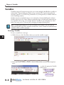
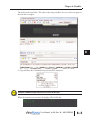
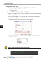
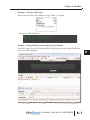
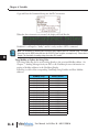
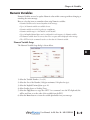
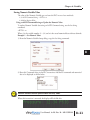
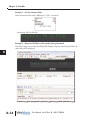
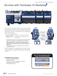
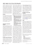
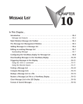
VARIABLES
CHAPTER
8
5
In This Chapter...
Variables . . . . . . . . . . . . . . . . . . . . . . . . . . . . . . . . . . . . . . . . . . . . . . . . . . . . . . . . . .8–2
Inserting a Variable . . . . . . . . . . . . . . . . . . . . . . . . . . . . . . . . . . . . . . . . . . . . . . . . .8–2
Editing a Variable . . . . . . . . . . . . . . . . . . . . . . . . . . . . . . . . . . . . . . . . . . . . . . . . . . .8–3
String Variables . . . . . . . . . . . . . . . . . . . . . . . . . . . . . . . . . . . . . . . . . . . . . . . . . . . . .8–4
String Variable Setup . . . . . . . . . . . . . . . . . . . . . . . . . . . . . . . . . . . . . . . . . . . . . . . .8–4
Setting String Variable Value . . . . . . . . . . . . . . . . . . . . . . . . . . . . . . . . . . . . . . . . . .8–6
Numeric Variables . . . . . . . . . . . . . . . . . . . . . . . . . . . . . . . . . . . . . . . . . . . . . . . . . . .8–9
Numeric Variable Setup . . . . . . . . . . . . . . . . . . . . . . . . . . . . . . . . . . . . . . . . . . . . . .8–9
Setting Numeric Variable Value . . . . . . . . . . . . . . . . . . . . . . . . . . . . . . . . . . . . . . .8–11
Chapter 8: Variables
1
2
3
4
5
6
7
8
9
10
11
12
13
14
A
B
C
D
Variables
ViewMarq supports Dynamic messages that can contain multiple embedded data variables in
each message. These variables may display string or numeric PLC register data updated in
real time by the PLC, by ASCII string commands or by writing directly to Modbus addresses
in the ViewMarq memory.
Variables may be used multiple times in one command yet formatted differently each time.
Variables may be used in as many different command strings as needed and formatted in any
way required for that string. For example, Numeric Variable #1 may be displayed as 500.0
mm in one string and or 50.00 cm just by changing the implied decimal places.
NOTE: The display format options such as color or character set for variables is set in the static text
string where the <DEC> and <STR> commands are used; that is, color or character set commands do not
work with, <SETS> or <SETV> commands.
Inserting a Variable
To insert a variable into a message:
1) Click in the area of the Text Editor where you want the variable to appear.
2) Select either Insert Numeric Variable or Insert String Variable from the Insert dropdown
menu.
...or select the appropriate Variable
toolbar button.
8–2
User Manual, 1st Ed. Rev. B – MD-USER-M
Chapter 8: Variables
The Variable Setup Dialog will open.
3) Select Insert to insert the variable into the Text Editor and into the Command String
Editing a Variable
To edit a variable in a message, simply double click on the variable in the Text Editor and the
setup window will open.
User Manual, 1st Ed. Rev. B – MD-USER-M
8–3
1
2
3
4
5
6
7
8
9
10
11
12
13
14
A
B
C
D
Chapter 8: Variables
1
2
3
4
5
6
7
8
9
10
11
12
13
14
A
B
C
D
String Variables
String Variables are used to update ASCII text in a message without resending the entire
message.
There are a few key items to remember when using String variables:
• String Variables can be inserted anywhere in the message.
• Up to 16 string variables can be used in a single message.
• 16 individual string variables are available for use
• String variables can be up to 100 characters in length.
• If a string variable value has not been set, then a number of blank spaces will be displayed
equal to the number of characters in the variable in that portion of the message.
• The <SETS n>string</SETS> command string is used to set a string variable. This is
covered later in this chapter.
String Variable Setup
The String Variable Setup dialog is shown below.
1) Select the Variable Number (1 to 16).
2) Select the Size of the string (100 characters maximum).
3) Select the Copy button to copy the <SETS n>string </SETS> command onto the PC
clipboard. (This will be used later to set the value of the string from the PLC.)
4) Select the Insert button to insert the variable placeholder into your message.
8–4
User Manual, 1st Ed. Rev. B – MD-USER-M
Chapter 8: Variables
The result can be seen below. The value of the string variable is not set, so there are spaces in
the area that it occupies.
5) Copy and Paste the Command String into the PLC instruction.
ATTENTION
Attention!: Command Strings should be sent at least 100 ms apart.
When the instruction is executed, the display will look like this.
User Manual, 1st Ed. Rev. B – MD-USER-M
8–5
1
2
3
4
5
6
7
8
9
10
11
12
13
14
A
B
C
D
Chapter 8: Variables
Setting String Variable Value
1
2
3
4
5
6
7
8
9
10
11
12
13
14
A
B
C
D
The value of the String Variable gets set from the PLC in one of two methods::
1) ASCII Command String - <SETS n>string</SETS>
2) Modbus Register Write
Using an ASCII Command String to Update the String Value
To update String Variable data using an ASCII Command string, use the Set String command
<SETS n>string</SETS>
Where n is the string number (1 – 16) and string is the actual text that you wish to display.
Example 1 – Set String Value
1) From the String Variable Setup dialog copy the Set String command.
2) Paste this Command String in the PLC instruction; Add the ID command and the string =
“World” to be displayed
ATTENTION
Attention!: Variables should be updated no more than every 100ms.
When the above instruction is executed, the display will now look like this.
8–6
User Manual, 1st Ed. Rev. B – MD-USER-M
Chapter 8: Variables
Example 2 – New Set String Value
If the instruction below with a different string=”Smiley” is executed…
...the message will look like this.
Example 3 – String Variable used in another String Command
If another String is sent to the ViewMarq LED Display using the same String Variable, the
same value will be displayed.
User Manual, 1st Ed. Rev. B – MD-USER-M
8–7
1
2
3
4
5
6
7
8
9
10
11
12
13
14
A
B
C
D
Chapter 8: Variables
Copy and Paste the Command String into the PLC instruction.
1
2
3
4
5
6
7
8
9
10
11
12
13
14
A
B
C
D
When the above instruction is executed, the display will look like this.
Variable #1 is still equal to “Smiley” until it is set by another <SETS> command.
NOTE: The conditions for executing the instructions above depend upon the controller used. The above
instructions are the SEND instruction from the CLICK PLC and are given as examples only. Please refer to
Chapter 7 for the details of sending strings from other PLC models.
Using Modbus to Update the String Value
The String Value may also be set by writing directly to the associated Modbus address. See
Chapter 7 - Sending Messages from your PLC to the ViewMarq for more information on
writing to Modbus addresses in the ViewMarq Display.
Following is a table of the corresponding ViewMarq String Variables and Slave Modbus
addresses.
8–8
ViewMarq String
Modbus Address
String Variable #1
String Variable #2
String Variable #3
String Variable #4
String Variable #5
String Variable #6
String Variable #7
String Variable #8
String Variable #9
String Variable #10
String Variable #11
String Variable #12
String Variable #13
String Variable #14
String Variable #15
String Variable #16
400200
400250
400300
400350
400400
400450
400500
400550
400600
400650
400700
400750
400800
400850
400900
400950
User Manual, 1st Ed. Rev. B – MD-USER-M
Chapter 8: Variables
Numeric Variables
Numeric Variables are used to update Numeric values within a message without changing or
resending the entire message.
Here are a few key items to remember when using Numeric variables:
• Numeric Variables can be inserted anywhere in the message.
• Up to 32 Numeric variables are available for use.
• Numeric variables are 32 bit, bi-polar, two compliment.
• Numeric variable range is - 2147483647 to 2147483647.
• Up to 10 Implied decimal places can be configured for each instance of a Numeric variable.
• If a Numeric variable has not been set, then zeroes or spaces will be displayed in the message.
• The <SETV n 1234> command is used to set the value of a Numeric variable.
Numeric Variable Setup
The Numeric Variable Setup dialog is shown below.
1) Select the Variable Number ( 1 to 32).
2) Select the Size of the Number (10 digits maximum, 11th place for sign).
3) Select the Implied Decimal place up to 10.
4) Select Leading Spaces or Leading Zeros.
5) Select the Copy button to copy the <SETV 1 n> command onto the PC clipboard (this
will be used later to set the value of the variable from the PLC).
6) Select the Insert button to insert the variable placeholder into your message.
User Manual, 1st Ed. Rev. B – MD-USER-M
8–9
1
2
3
4
5
6
7
8
9
10
11
12
13
14
A
B
C
D
Chapter 8: Variables
1
2
3
4
5
6
7
8
9
10
11
12
13
14
A
B
C
D
The result can be seen below. The value of the numeric variable is not set, so there are zeros
with leading spaces in the area that it occupies.
7) Copy and Paste the Command String into the PLC instruction.
ATTENTION
Attention!: Command Strings should be sent at least 100 ms apart.
When the above instruction is executed, the display will look like this.
8–10
User Manual, 1st Ed. Rev. B – MD-USER-M
Chapter 8: Variables
Setting Numeric Variable Value
The value of the Numeric Variable gets set from the PLC in one of two methods::
1) 1) ASCII Command String - <SETV 1 n>
2) Modbus Register Write
Using an ASCII Command String to Update the Numeric Value
To update Numeric Variable data using an ASCII Command string, use the Set String
command.
<SETV 1 n>
Where 1 is the variable number (1 – 32) and n is the actual numerical data without decimals.
Example 1 – Set Numeric Value
1) From the Numeric Variable Setup dialog, copy the Set String command.
2) Paste this Command String in the PLC instruction; Add the ID command and numerical
data to be displayed as shown below.
ATTENTION
Attention!: Variables should be updated no more than every 100ms.
When this instruction is executed, the display will look like this.
User Manual, 1st Ed. Rev. B – MD-USER-M
8–11
1
2
3
4
5
6
7
8
9
10
11
12
13
14
A
B
C
D
Chapter 8: Variables
Example 1 – Set New Numeric Value
If the instruction below with a different n=”5432” is executed…
1
2
3
4
5
6
7
8
9
10
11
12
13
14
A
B
C
D
…the message will look like this.
Example 3 – Numerical Variable used in another String Command
If another String is sent to the ViewMarq LED Display using the same String Variable, the
same value will be displayed.
8–12
User Manual, 1st Ed. Rev. B – MD-USER-M
Chapter 8: Variables
Copy and Paste the Command String into the PLC instruction.
When the above instruction is executed, the display will look like this.
Variable #1 is still equal to “5432” until it is set by another <SETV> command.
NOTE: The conditions for executing the instructions above depend upon the controller used. The above
instructions are the SEND instruction from the CLICK PLC and are given as examples only. Please refer to
Chapter 7 for the details of sending strings from other PLC models.
User Manual, 1st Ed. Rev. B – MD-USER-M
8–13
1
2
3
4
5
6
7
8
9
10
11
12
13
14
A
B
C
D
Chapter 8: Variables
Using Modbus to Update the String Value
The Numeric Value may also be set by writing directly to the associated Modbus address. See
Chapter 7 - Sending Messages from your PLC to the ViewMarq for more information on
writing to Modbus addresses in the ViewMarq Display.
Below is a table of the corresponding ViewMarq Numeric Variables and Slave Modbus
addresses.
1
2
3
4
5
6
7
8
9
10
11
12
13
14
A
B
C
D
ViewMarq Variable
Numeric Variable #1
Numeric Variable #2
Numeric Variable #3
Numeric Variable #4
Numeric Variable #5
Numeric Variable #6
Numeric Variable #7
Numeric Variable #8
Numeric Variable #9
Numeric Variable #10
Numeric Variable #11
Numeric Variable #12
Numeric Variable #13
Numeric Variable #14
Numeric Variable #15
Numeric Variable #16
Numeric Variable #17
Numeric Variable #18
Numeric Variable #19
Numeric Variable #20
Numeric Variable #21
Numeric Variable #22
Numeric Variable #23
Numeric Variable #24
Numeric Variable #25
Numeric Variable #26
Numeric Variable #27
Numeric Variable #28
Numeric Variable #29
Numeric Variable #30
Numeric Variable #31
Numeric Variable #32
8–14
Modbus Address
High Word
Low Word
400100
400102
400104
400106
400108
400110
400112
400114
400116
400118
400120
400122
400124
400126
400128
400130
400132
400134
400136
400138
400140
400142
400144
400146
400148
400150
400152
400154
400156
400158
400160
400162
400101
400103
400105
400107
400109
400111
400113
400115
400117
400119
400121
400123
400125
400127
400129
400131
400133
400135
400137
400139
400141
400143
400145
400147
400149
400151
400153
400155
400157
400159
400161
400163
User Manual, 1st Ed. Rev. B – MD-USER-M