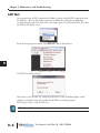
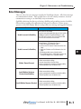
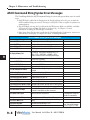
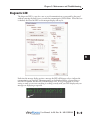
1
MAINTENANCE AND
TROUBLESHOOTING
CHAPTER
9
In This Chapter...
Introduction . . . . . . . . . . . . . . . . . . . . . . . . . . . . . . . . . . . . . . . . . . . . . . . . . . . . . . .9–2
Updating Firmware . . . . . . . . . . . . . . . . . . . . . . . . . . . . . . . . . . . . . . . . . . . . . . . . . .9–2
Load Firmware Message . . . . . . . . . . . . . . . . . . . . . . . . . . . . . . . . . . . . . . . . . . . . .9–4
Reboot LED Display . . . . . . . . . . . . . . . . . . . . . . . . . . . . . . . . . . . . . . . . . . . . . . . . . .9–4
Reset Factory Defaults . . . . . . . . . . . . . . . . . . . . . . . . . . . . . . . . . . . . . . . . . . . . . . .9–5
LED Test . . . . . . . . . . . . . . . . . . . . . . . . . . . . . . . . . . . . . . . . . . . . . . . . . . . . . . . . . . .9–6
Error Messages . . . . . . . . . . . . . . . . . . . . . . . . . . . . . . . . . . . . . . . . . . . . . . . . . . . . .9–7
ASCII Command String Syntax Error Messages . . . . . . . . . . . . . . . . . . . . . . . . . . . .9–8
Diagnostic LED . . . . . . . . . . . . . . . . . . . . . . . . . . . . . . . . . . . . . . . . . . . . . . . . . . . . .9–9
Chapter 9: Maintenance and Troubleshooting
Introduction
Even though the ViewMarq requires virtually no maintenance, there are a few steps you can
1
take to insure the longevity of your product and to maintain the warranty, safety and
environmental ratings.
2
• To maintain the NEMA ratings the cable entry points in the back cover must be properly sealed.
The ViewMarq is provided with cable glands to seal all of these points whether a cable is used or
not. The provided covers must be properly installed as well.
3
• To provide for proper heat dissipation, keep the ViewMarq clear of all dust and debris.
• Regularly inspect ViewMarq mounting brackets and the mounting surfaces.
4
• To maintain viewing distances and clarity, clean the lens with a damp cloth as needed.
5
NOTE: To maintain UL508 rating, Flexible Conduit must be used for all conductors entering the message
display.
6
7 Updating Firmware
Occasionally new firmware will be released to enhance your ViewMarq. The firmware may
be downloaded from automationdirect.com/downloads and updated using the ViewMarq
8
software.
1) Select the Link for the display to update.
9
10
11
12
2) From the Setup dropdown menu, select Update Firmware as shown.
13
14
A
B
C
D
9–2
User Manual, 1st Ed. Rev. B – MD-USER-M
Chapter 9: Maintenance and Troubleshooting
3) The Update Firmware dialog will open. The panel information will be read from the
slected Link; Display Name, Firmware version and Link Name.
The Firmware is in two parts:
A1 – ASCII character set version
FW – Base Firmware (Operating System).
4) Select the Blink button to make sure you have the correct display.
5) Select the Browse button and navigate to the location you saved the firmware file. It
should be named something like VM-A1015300.vmf .
6) Select the Update button. You will see a warning like the one shown below. Make sure all
messages saved in the message list have been saved on your hard drive. They will be cleared
from the panel. All communication settings will be preserved in the panel.
User Manual, 1st Ed. Rev. B – MD-USER-M
9–3
1
2
3
4
5
6
7
8
9
10
11
12
13
14
A
B
C
D
Chapter 9: Maintenance and Troubleshooting
7) Click the Yes button. While upgrading, the software will display an activity bar. As long as
the green shade in the activity bar is moving, the display is still upgrading. When the
activity bar stops, click the Close button. The ViewMarq will display the following
messages during the firmware update.
1
a) FW Loading
2
b) FW Updating
c) Load Firmware
3
d)FW Loading
8) When the firware update is complete, the display will reset and the default startup screen
4
begins to scroll.
Load Firmware Message
5
If the software has completed the Firmware Update process, but the ViewMarq shows a Load
Firmware message, repeat the firmware update process. Do not change any communication
settings, simply repeat step 5.
6
LED Display
7 RebootSometimes
you may wish to clear the display or power cycle the display but it is not within
reach. To Reboot the LED Display, select the Link for the Display to reboot.
8
9
10
11
From the Setup dropdown menu, select Reboot LED Display as shown.
12
13
14
A
B
C
D
9–4
User Manual, 1st Ed. Rev. B – MD-USER-M
Chapter 9: Maintenance and Troubleshooting
Reset Factory Defaults
For troubleshooting purposes, there may be a need to reset the display to factory defaults. To
return the LED display to factory defaults, select the Link for the Display to reset.
From the Setup dropdown menu, select Reset Factory Defaults as shown.
A Reset Factory Defaults action will set communication parameters to the defaults:
• The ViewMarq name will be reset
• The IP address will be set back to Obtain Address from DHCP Server
• Port 1 will be set to ASCII, node address 1, baud rate 38400bps, 8 data bits, odd parity and 1 stop
bit
• Port 2 will be set to Modbus, node address 1, baud rate 38400bps, 8 data bits, odd parity and 1
stop bit
Click Yes to reset the display back to factory defaults.
User Manual, 1st Ed. Rev. B – MD-USER-M
9–5
1
2
3
4
5
6
7
8
9
10
11
12
13
14
A
B
C
D
Chapter 9: Maintenance and Troubleshooting
1
2
3
4
5
6
7
8
9
10
11
12
13
14
A
B
C
D
LED Test
If you suspect that an LED component has failed, you may verify the LED components with
the LED test. The test will initiate a pattern of scrolling lines cycling horizontally then
vertically through each of the three colors (red, amber, green). To perform an LED Test, select
the Link for the display to test.
From the Setup dropdown menu, select Run LED Test as shown below.
The LED Test dialog will open
Select Start to run the LED test. Check all of the LEDs on the ViewMarq display as they
change to red, amber and green to make sure all LEDs are working properly.
Select Stop or Close to stop the LED test.
NOTE: LEDs are NOT user replaceable.
9–6
User Manual, 1st Ed. Rev. B – MD-USER-M
Chapter 9: Maintenance and Troubleshooting
Error Messages
There are only a few error messages issued by the ViewMarq Software. All of these messages
are communication related. They typically have to do with a faulty connection, incorrect
communication settings or an electrically noisy environment.
Qualified technicians that know good wiring, shielding and grounding practices should be
followed when installing all communication and power conductors to ensure proper
operation of the LED display. Below is each possible error message and suggested solutions.
Error
Suggested Action
Unable to connect to ViewMarq
Serial: Serial Port Unavailable
Ensure that some other application does not have control of
the COM port and that the specified COM port is valid
Note: USB serial converters may choose different COM
ports when disconnected and re-connected
Unable to connect to ViewMarq
Ethernet: Ethernet - TCP Connection Timeout
1) Check the Cable and Ethernet switch
2) Increase the TCP Connect Timeout time in the Link
Setup
3) Check the IP Address and Port Number in the Link
Setup
4) Eliminate possible causes of electrical noise
5) Try to PING the display. If PING fails ensure that the
PC and the display are on compatible subnets.
Modbus Timeout Occurred
1) Check communication settings
2) Increase timeout time in the Link Setup
3) Insure a good physical connection and cable condition
4) Eliminate possible causes of electrical noise
Invalid Modbus Checksum
Received from ViewMarq
1) Check communication settings
2) Insure a good physical connection and cable condition
3) Eliminate possible causes of electrical noise
1) Check communication settings
Invalid Modbus Response Received 2) Insure a good physical connection and cable condition
3) Eliminate possible causes of electrical noise
User Manual, 1st Ed. Rev. B – MD-USER-M
9–7
1
2
3
4
5
6
7
8
9
10
11
12
13
14
A
B
C
D
Chapter 9: Maintenance and Troubleshooting
1
2
3
4
5
6
7
8
9
10
11
12
13
14
A
B
C
D
ASCII Command String Syntax Error Messages
The ViewMarq checks the ASCII command String for errors and reports these error in several
ways.
1) If ASCII Reply is enabled in the Display, then the Display will respond on the port on which the
ASCII command String was received. This may be read by PLC’s that are capable of asynchronous
communications.
2) The ASCII Reply text may also be read from the ASCII Response Buffer over Modbus or Modbus
TCP started at register 415000. The buffer is 512 bytes long. See Chapter 7 for more
information on reading the ASCII Reply over Modbus.
3) If the Syntax Error Check option is enabled in the ViewMarq Display Configuration, syntax errors
will scroll across the display. See Chapter 6 for more on enabling this feature.
ASCII Command String Syntax Error Messages
Error Message
Description
E1: Invalid SETS format
Missing string number or out of range
E2: Invalid SETV format
Missing variable number or out of range
E3: Invalid Pause Time
Pause time must between 0 and 1000 Seconds
E5: Invalid SETS Value
SETS String too long, maximum is 100 characters
E6: Display Memory Full
Use the CLR command to prevent memory from
becoming full. There can be a maximum of 31 <T>,
<DEC>, <STR>, <PORTPAR>, <IPADDR>, <VER>,
<NAME> commands total in the displayed message.
E7: Text Memory Full
Maximum text characters that can be displayed is 1500.
Use the <CLR> command
E8: Invalid STR/DEC Format
Syntax error in STR or DEC command
E9: Invalid PORTPAR Format
Syntax error in PORTPAR command
E10: Parameter Out of Range
E12: Download Error
CS parameter out of range
A DO command is calling a string with an embedded DO
command
Error Downloading strings (Future)
E13: Invalid STR String Number
String number must be 1-16
E14: Invalid DEC String Number
Variable number must be 1-32
E16: Invalid DEC Size
Maximum length is 11 characters
E17: Invalid STR Size
Maximum length is 100 characters
E11: DO command not allowed
Notes
E18: Invalid Message Number in DO Invalid Message Number, Message does not exist (Future)
E19: Invalid Message Number in DS Invalid Message Number, Message does not exist (Future)
E20: Status Buffer is Empty
Status buffer in empty probably because STATUS
command is used before any other command
E21: Syntax error at pos #
General Syntax error at position #
E22: Syntax error in DO at pos #
E24: Invalid ID Format
General Syntax error in DO at position # (Future)
Error in MSG # %d - Error is displayed on ViewMarq
(Future)
ID number must be between 0 - 247
E25: Missing <ID #>
ID command contains no ID number
E23: Error in MSG # %d:
9–8
Syntax errors could be caused
by sending ASCII strings too
fast with no handshaking.
These are not displayed
errors. They will be stored in
the Status register (411500)
User Manual, 1st Ed. Rev. B – MD-USER-M
Chapter 9: Maintenance and Troubleshooting
Diagnostic LED
The diagnostic LED is a way for a user to see if communications are successful to the panel
without removing the back covers to watch the communication LED’s flicker. When this box
is checked, the lower left LED on the marquee display will stay lit.
Each time the message display receives a message the LED will change color to indicate the
communication was received. The message may not be displayed due to a Syntax Error or
incorrect ID number, but the LED will still change color. It is a good practice to set this
setting on until you are sure everything is working correctly with your LED display and your
messages are displaying as expected.
User Manual, 1st Ed. Rev. B – MD-USER-M
9–9
1
2
3
4
5
6
7
8
9
10
11
12
13
14
A
B
C
D