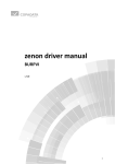
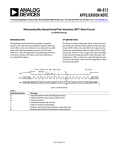
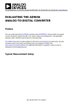
1
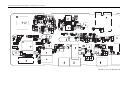
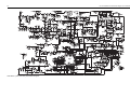
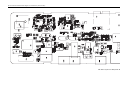
Computer Software Copyrights The Motorola products described in this manual may include copyrighted Motorola computer programs stored in semiconductor memories or other media. Laws in the United States and other countries preserve for Motorola certain exclusive rights for copyrighted computer programs, including, but not limited to, the exclusive right to copy or reproduce in any form, the copyrighted computer program. Accordingly, any copyrighted Motorola computer programs contained in the Motorola products described in this manual may not be copied, reproduced, modified, reverse-engineered, or distributed in any manner without the express written permission of Motorola. Furthermore, the purchase of Motorola products shall not be deemed to grant, either directly or by implication, estoppel or otherwise, any license under the copyrights, patents or patent applications of Motorola, except for the normal non-exclusive license to use that arises by operation of law in the sale of a product. Technical Information Updates As we continue to make engineering enhancements to our products, the information in our Service Manuals need to be updated accordingly. If you wish to be informed of these updates, kindly fill in and fax us your details. Fax to: 6-04-6124944 The Technical Publications Coordinator, Media and Communications, R&D Department, Motorola Penang. Your Details Name/Contact Person: Company Name: Address: Telephone No.: Fax No.: Email Address: How would you like to receive the update notification? Through: mail email fax Manual No.: 6816102H01 Kindly complete the Service Manual Feedback Form on the next page to help us ensure that you receive the most accurate and complete information. Service Manual Feedback Form We believe that reports from users provide valuable information for producing quality manuals. Kindly take a few moments to provide feedback on this manual. Thank you for your cooperation. Fax to: 6-04-6124944 Not Covered in this Manual Size Too Small Size Adequate Confusing Clear Incorrect Correct Incomplete Complete The Technical Publications Coordinator, Media and Communications, R&D Department, Motorola Penang. 1. Please check all the appropriate boxes: Disassembly Procedures Alignment Procedures Exploded Views Schematic Diagrams Circuit Board Details Electrical Parts List Exploded View Parts List 2. How do you rate this particular Service Manual? excellent very good good fair poor 3. Did this Service manual provide you with the information necessary to service and maintain the specific equipment? very much so generally yes to some extent no 4. We would appreciate any corrections or recommendations for improving this manual. Please include the specific page number(s) of the diagram or procedure in question. 5. General comments/suggestions: Manual No.: 6816102H01 i DOCUMENT HISTORY The following major changes have been implemented in this manual since the previous edition: Edition 6816102H01-A Description Initial Edition Date Mar. 2007 ii Notes iii Safety Information Product Safety and RF Energy Exposure Booklet for Portable Two-Way Radios The information provided in this document supersedes the general safety information contained in user guides published prior to February 2002. BEFORE USING THIS RADIO, READ THE FOLLOWING INFORMATION WHICH CONTAINS IMPORTANT OPERATING INSTRUCTIONS FOR SAFE USAGE AND RF ENERGY AWARENESS AND CONTROL INFORMATION AND OPERATIONAL INSTRUCTIONS FOR COMPLIANCE WITH RF ENERGY EXPOSURE LIMITS IN APPLICABLE NATIONAL AND INTERNATIONAL STANDARDS. ALSO READ THE OPERATIONAL INSTRUCTIONS FOR SAFE USAGE. FOR RADIOS THAT HAVE BEEN APPROVED AS INTRINSICALLY SAFE, READ THE INSTRUCTIONS AND INFORMATION ON INTRINSIC SAFETY ON PAGE vii. RF Energy Exposure Awareness and Control Information and Operational Instructions for Occupational Use NOTICE: This radio is intended for use in occupational/controlled conditions where users have full knowledge of their exposure and can exercise control over their exposure to meet the occupational limits in FCC and International standards. This radio device is NOT authorized for general population or consumer use. This two-way radio uses electromagnetic energy in the radio frequency (RF) spectrum to provide communications between two or more users over a distance. It uses radio frequency (RF) energy or radio waves to send and receive calls. RF energy is one form of electromagnetic energy. Other forms include, but are not limited to, sunlight and x-rays. RF energy, however, should not be confused with these other forms of electromagnetic energy, which when used improperly, can cause biological damage. Very high levels of x-rays, for example, can damage tissues and genetic material. Experts in science, engineering, medicine, health, and industry work with organizations to develop standards for safe exposure to RF energy. These standards provide recommended levels of RF exposure for both workers and the general public. These recommended RF exposure levels include substantial margins of protection. All Motorola two-way radios are designed, manufactured, and tested to ensure they meet government-established RF exposure levels. In addition, manufacturers also recommend specific operating instructions to users of two-way radios. These instructions are important because they inform users about RF energy exposure and provide simple procedures on how to control it. Please refer to the following websites for more information on what RF energy exposure is and how to control your exposure to assure compliance with established RF exposure limits: http://www.fcc.gov/oet/rfsafety/rf-faqs.html http://www.osha.gov/SLTC/radiofrequencyradiation/index.html Federal Communication Commission (FCC) Regulations The FCC rules require manufacturers to comply with the FCC RF energy exposure limits for portable two-way radios before they can be marketed in the U.S. When two-way radios are used as a consequence of employment, the FCC requires users to be fully aware of and able to control their exposure to meet occupational requirements. iv Exposure awareness can be facilitated by the use of a product label directing users to specific user awareness information. Your Motorola two-way radio has a RF exposure product label. Also, your Motorola user manual, or separate safety booklet includes information and operating instructions required to control your RF exposure and to satisfy compliance requirements. Compliance with RF Exposure Standards Your Motorola two-way radio is designed and tested to comply with a number of national and International standards and guidelines (listed below) for human exposure to radio frequency electromagnetic energy. This radio complies with the IEEE (FCC) and ICNIRP exposure limits for occupational/controlled RF exposure environments at operating duty factors of up to 50% talk-50% listen and is authorized by the FCC for occupational use only. In terms of measuring RF energy for compliance with these exposure guidelines, your radio generates measurable RF energy only while it is transmitting (during talking), not when it is receiving (listening) or in standby mode. NOTE:The approved batteries, supplied with this radio, are rated for a 5-5-90 duty factor (5% talk5% listen-90% standby) even though this radio complies with FCC occupational exposure limits and may operate at duty factors of up to 50% talk. Your Motorola two-way radio complies with the following RF energy exposure standards and guidelines: • • • • • • • United States Federal Communications Commission, Code of Federal Regulations; 47CFR part 2 sub-part J American National Standards Institute (ANSI) / Institute of Electrical and Electronic Engineers (IEEE) C95. 1-1992 Institute of Electrical and Electronic Engineers (IEEE) C95.1-1999 Edition International Commission on Non-Ionizing Radiation Protection (ICNIRP) 1998 Ministry of Health (Canada) Safety Code 6. Limits of Human Exposure to Radiofrequency Electromagnetic Fields in the Frequency Range from 3 kHz to 300 GHz, 1999 Australian Communications Authority Radiocommunications (Electromagnetic Radiation Human Exposure) Standard, 2003 ANATEL ANNEX to Resolution No. 303 of July 2, 2002 "Regulation of limitation of exposure to electrical, magnetic and electromagnetic fields in the radio frequency range between 9 KHz and 300 GHz" and "Attachment to resolution # 303 from July 2, 2002" "Additional Requirements for SMR, Cellular and PCS Product Certification" RF Exposure Compliance and Control Guidelines and Operating Instructions To control your exposure and ensure compliance with the occupational/controlled environment exposure limits, always adhere to the following procedures. Guidelines: • • • Do not remove the RF Exposure Label from the device. User awareness instructions should accompany device when transferred to other users. Do not use this device if the operational requirements described herein are not met. v Operating Instructions • • • • • Transmit no more than the rated duty factor of 50% of the time. To transmit (talk), push the PushTo-Talk (PTT) button. To receive calls, release the PTT button. Transmitting 50% of the time, or less, is important because this radio generates measurable RF energy exposure only when transmitting (in terms of measuring for standards compliance). Hold the radio in a vertical position in front of the face with the microphone (and other parts of the radio including the antenna) at least one inch (2.5 centimeters) away from the nose or lips. Antenna should be kept away from the eye. Keeping the radio at a proper distance is important since RF exposures decrease with increasing distance from the antenna. When worn on the body, always place the radio in a Motorola-approved clip, holder, holster, case, or body harness for this product. Using approved body-worn accessories is important because the use of non-Motorola-approved accessories may result in exposure levels, which exceed the FCC occupational/controlled environment RF exposure limits. If you are not using a body-worn accessory and are not using the radio in the intended use position in front of the face, ensure the antenna and the radio are kept at least one inch (2.5 centimeters) from the body when transmitting. Keeping the radio at a proper distance is important because RF exposures decrease with increasing distance from the antenna. Approved Accessories • • Use only Motorola-approved supplied or replacement antennas, batteries, and accessories. Use of Non-Motorola approved antennas, batteries, and accessories may exceed the FCC (IEEE) and ICNIRP RF exposure guidelines. For a list of Motorola-approved accessories, visit the following website, which lists approved accessories for your radio model: http://www.motorola.com/governmentandenterprise Additional Information For additional information on exposure requirements or other training information, visit http://www.motorola.com/rfhealth Electromagnetic Interference/Compatibility NOTE:Nearly every electronic device is susceptible to electromagnetic interference (EMI) if inadequately shielded, designed, or otherwise configured for electromagnetic compatibility. Facilities To avoid electromagnetic interference and/or compatibility conflicts, turn off your radio in any facility where posted notices instruct you to do so. Hospitals or health care facilities may be using equipment that is sensitive to external RF energy. Aircraft When instructed to do so, turn off your radio when on board an aircraft. Any use of a radio must be in accordance with applicable regulations per airline crew instructions. Medical Devices Pacemakers The Advanced Medical Technology Association (AdvaMed) recommends that a minimum separation of 6 inches (15 centimeters) be maintained between a handheld wireless radio and a pacemaker. These recommendations are consistent with those of the U.S. Food and Drug Administration. vi Persons with pacemakers should: • • • • ALWAYS keep the radio more than 6 inches (15 centimeters) from their pacemaker when the radio is turned ON. Not carry the radio in the breast pocket. Use the ear opposite the pacemaker to minimize the potential for interference. Turn the radio OFF immediately if there is any reason to suspect that interference is taking place. Hearing Aids Some digital wireless radios may interfere with some hearing aids. In the event of such interference, you may want to consult your hearing aid manufacturer to discuss alternatives. Other Medical Devices If you use any other personal medical device, consult the manufacturer of your device to determine if it is adequately shielded from RF energy. Your physician may be able to assist you in obtaining this information. Use of communication devices while driving Always check the laws and regulations on the use of radios in the areas where you drive. • • • Give full attention to driving and to the road. Use hands-free operation, if available. Pull off the road and park before making or answering a call, if driving conditions or regulations so require. Operational Warnings For vehicle with air bags Refer to vehicle manufacturer's manual prior to installation of electronic equipment to avoid interference with air bag wiring. Do not place a portable radio in the area over an air bag or in the air bag deployment area. Air bags inflate with great force. If a portable radio is placed in the air bag deployment area and the air bag inflates, the radio may be propelled with great force and cause serious injury to occupants of the vehicle. Potentially Explosive Atmospheres (Explosive atmospheres refers to hazard classified locations that may contain hazardous gas, vapors, or dusts.) Turn off your radio prior to entering any area with a potentially explosive atmosphere unless it is a portable radio type especially qualified for use in such areas as Intrinsically Safe (for example, Factory Mutual, CSA, UL, or CENELEC). Do not remove, install, or charge batteries in such areas. Sparks in a potentially explosive atmosphere can cause an explosion or fire resulting in bodily injury or even death. The areas with potentially explosive atmospheres referred to above include fueling areas such as below decks on boats, fuel or chemical transfer or storage facilities, and areas where the air contains chemicals or particles such as grain, dust or metal powders. Areas with potentially explosive atmospheres are often, but not always, posted. Blasting Caps And Blasting Areas To avoid possible interference with blasting operations, turn off your radio when you are near electrical blasting caps, in a blasting area, or in areas posted: "Turn off two-way radio." Obey all signs and instructions. vii Operational Cautions Antennas Do not use any portable radio that has a damaged antenna. If a damaged antenna comes into contact with your skin, a minor burn can result. Batteries All batteries can cause property damage and/or bodily injury, such as burns, if a conductive material such as jewelry, keys, or beaded chains touches exposed terminals. The conductive material may complete an electrical circuit (short circuit) and become quite hot. Exercise care in handling any charged battery, particularly when placing it inside a pocket, purse, or other container with metal objects. Intrinsically Safe Radio Information The Intrinsically safe approval unit refers to a product that has been approved as intrinsically safe by an approval agency (for example FM Approvals, CSA, UL, or Cenelec) and certifies that a particular product meets the Agency's applicable intrinsic safety standards for specific types of hazardous classified locations. A portable radio that has been approved for intrinsic safety will have Approval label attached to the radio to identify the unit as being Approved for specified hazardous atmospheres. This label specifies the hazardous Class/Division/Group along with the part number of the battery that must be used. The intrinsically safe approval label will be located on the portable radio unit. Operational Cautions for Intrinsic Safe Equipment • Do not operate radio communications equipment in a hazardous atmosphere unless it is a type especially qualified (for example, FM, UL, CSA, or CENELEC approved). An explosion or fire may result. • Do not operate a radio unit that has been approved as intrinsically safe product in a hazardous atmosphere if it has been physically damaged (for example, cracked housing). An explosion or fire may result. • Do not replace or charge batteries in a hazardous atmosphere. Contact sparking may occur while installing or removing batteries and cause an explosion or fire. Warnings for Radios Approved as Intrinsically Safe Radios must ship from the Motorola manufacturing facility with the hazardous atmosphere capability and the intrinsic safety approval labelling (FM, UL, CSA, CENELEC). Radios will not be upgraded to this capability and labeled once they have been shipped to the field. viii A modification changes the unit's hardware from its original design configuration. Modifications can only be made by the original product manufacturer. • Do not replace or change accessories in a hazardous atmosphere. Contact sparking may occur while installing or removing accessories and cause an explosion or fire. • Turn the radio off before removing or installing a battery or accessory. • Do not disassemble an intrinsically safe product in any way that exposes the internal circuits of the unit. • Failure to use an intrinsically safe approved battery or Approved accessories specifically approved for the radio unit may result in the dangerously unsafe condition of an unapproved radio combination being used in a hazardous location. • Unauthorized or incorrect modification of the intrinsically safe approved Product will negate the approval rating of the product. • Incorrect repair or relabeling of any intrinsically safe Agency approved radio could adversely affect the Approval rating of the unit. • Use of a radio that is not intrinsically safe in a hazardous atmosphere could result in serious injury or death. Repair REPAIRS FOR MOTOROLA PRODUCTS WITH INTRINSICALLY SAFE APPROVAL ARE THE RESPONSIBILITY OF THE USER. • Repairs to a Motorola FM approved radio product should only be done at a location that has been FM audited under the FM 3605 repairs and service standard. • Contact Motorola for assistance regarding repairs and service of Motorola intrinsically safe equipment. A repair constitutes something done internally to the unit that would bring it back to its original condition. Items not considered as repairs are those in which an action is performed on a unit which does not require the outer casing of the unit to be opened in a manner that exposes the internal electrical circuits of the unit. Do Not Substitute Options or Accessories The Motorola communications equipment certified as intrinsically safe by the approving agency, (FM, UL, CSA, CENELEC) is tested as a complete system which consists of the listed agency Approved portable, Approved battery, and Approved accessories or options, or both. This Approved portable and battery combination must be strictly observed. There must be no substitution of items, even if the substitute has been previously Approved with a different Motorola communications equipment unit. Approved configurations are listed by the Approving Agency (FM, UL, CSA, CENELEC). The intrinsically safe Approval label affixed to radio refers to the intrinsically safe classification of that radio product, and the approved batteries that can be used with that system. The manual PN referenced on the intrinsically safe approval label identifies the approved Accessories and or options that can be used with that portable radio unit. Using a non Motorola intrinsically safe battery and or accessory with the Motorola approved radio unit will void the intrinsically safe approval of that radio unit. Table of Contents Document History..............................................................................................i Safety Information ........................................................................................... iii Section 1 INTRODUCTION 1.0 2.0 3.0 4.0 Scope of Manual....................................................................................................1-1 Warranty and Service Support...............................................................................1-1 2.1 Warranty Period and Return Instructions ........................................................1-1 2.2 After Warranty Period......................................................................................1-2 2.3 Piece Parts .....................................................................................................1-2 2.4 Technical Support ..........................................................................................1-2 2.5 Further Assistance From Motorola ..................................................................1-3 Radio Model Information........................................................................................1-3 Radio Features ......................................................................................................1-4 Section 2 THEORY OF OPERATION 1.0 2.0 3.0 4.0 Overview ................................................................................................................2-1 1.1 Purpose ...........................................................................................................2-1 1.2 General Description.........................................................................................2-1 Receiver System....................................................................................................2-1 2.1 Front-End ........................................................................................................2-1 2.2 First Mixer........................................................................................................2-2 2.3 IF Amplifier ......................................................................................................2-2 2.4 Squelch ...........................................................................................................2-2 Transmitter System and PLL Synthesizer .............................................................2-3 3.1 TX Power Stage ..............................................................................................2-3 3.2 Antenna Switch ...............................................................................................2-3 3.3 Low Pass Filter................................................................................................2-3 3.4 Auto-Power Control .........................................................................................2-4 3.5 PLL Synthesizer ..............................................................................................2-4 Audio and Control Circuit .......................................................................................2-5 4.1 RX Audio .........................................................................................................2-5 4.2 RX Sub-Audible Decode Circuit ......................................................................2-6 4.3 TX Audio..........................................................................................................2-6 4.4 TX Sub-Audible Encode Circuit.......................................................................2-6 4.5 Microprocessor................................................................................................2-6 Section 3 VHF BAND 1 (136–150 MHz) INFORMATION 1.0 RF Circuit Board and Schematic Diagram for VHF Band 1 (136–150 MHz) .........3-2 VHF Band 1 (136–150 MHz) Main Board Top Side...............................................3-2 VHF Band 1 (136–150 MHz) Main Board Bottom Side .........................................3-3 VHF Band 1 (136–150 MHz) Schematic Diagram .................................................3-4 Section 4 VHF BAND 2 (150–174 MHz) INFORMATION (150–174 MHz) 1.0 RF Circuit Board and Schematic Diagram for VHF Band 2 (150–174 MHz) .........4-2 VHF Band 2 (150–174 MHz) Main Board Top Side...............................................4-2 VHF Band 2 (150–174 MHz) Main Board Bottom Side .........................................4-3 VHF Band 2 (150–174MHz) Schematic Diagram ..................................................4-4 Section 5 UHF BAND 1 (403–425 MHz) Information 1.0 RF Circuit Board and Schematic Diagram for UHF Band 1 (403–425 MHz) ........5-2 UHF Band 1 (403–425 MHz) Main Board Top Side ..............................................5-2 UHF Band 1 (403–425 MHz) Main Board Bottom Side .........................................5-3 UHF Band 1 (403–425 MHz) Schematic Diagram .................................................5-4 Section 6 UHF Band 2 (450–470 MHz) Information 1.0 RF Circuit Board and Schematic Diagram for UHF Band 2 (450–470 MHz) .........6-2 UHF Band 2 (450–470 MHz) Main Board Top Side ..............................................6-2 UHF Band 2 (450–470 MHz) Main Board Bottom Side .........................................6-3 UHF Band 2 (450–470 MHz) Schematic Diagram .................................................6-4 Section 7 UHF Band 4 (490–512 MHz) Information 1.0 RF Circuit Board and Schematic Diagram for UHF Band 4 (490–512 MHz) .........7-2 UHF Band 4 (490–512 MHz) Main Board Top Side ..............................................7-2 UHF Band 4 (490–512 MHz) Main Board Bottom Side .........................................7-3 UHF Band 4 (490–512 MHz) Schematic Diagram .................................................7-4 Appendix A Motorola Support Details for the Europe, Middle East and Africa Region A.1 European Radio Support Centre (ERSC) .............................................................A-1 A.2 Technical Support .................................................................................................A-1 Scope of Manual 1-1 Section 1 INTRODUCTION 1.0 Scope of Manual This manual is intended for use by service technicians familiar with similar types of equipment. It contains service information required for the equipment described and is current as of the printing date. Changes which occur after the printing date may be incorporated by a complete Manual revision or alternatively as additions. NOTE Before operating or testing these units, please read the Safety Information Section in the front of this manual. 2.0 Warranty and Service Support Motorola offers long term support for its products. This support includes full exchange and/or repair of the product during the warranty period, and service/ repair or spare parts support out of warranty. Any "return for exchange" or "return for repair" by an authorized Motorola Dealer must be accompanied by a Warranty Claim Form. Warranty Claim Forms are obtained by contacting an Authorized Motorola Dealer. 2.1 Warranty Period and Return Instructions The terms and conditions of warranty are defined fully in the Motorola Dealer or Distributor or Reseller contract. These conditions may change from time to time and the following notes are for guidance purposes only. In instances where the product is covered under a "return for replacement" or "return for repair" warranty, a check of the product should be performed prior to shipping the unit back to Motorola. This is to ensure that the product has been correctly programmed or has not been subjected to damage outside the terms of the warranty. NOTE For service technicians in the Latin America Countries Region For any warranty claims in the Latin America Countries region, please open a case using the "Contact Us" feature within Motorola Online at https://businessonline.motorola.com/ . Prior to shipping any radio back to the appropriate Motorola warranty depot, please contact Customer Resources (Please see page 1-2). All returns must be accompanied by a Warranty Claim Form, available from your Customer Services representative. Products should be shipped back in the original packaging, or correctly packaged to ensure no damage occurs in transit. 1-2 2.2 Warranty and Service Support After Warranty Period NOTE For service technicians in the Latin America Countries Region After Warranty Period claims in the Latin America Countries region are handled through the Motorola Authorized Service Provider (SAM) Network. To find the nearest SAM, please go to Motorola Resource Center in Motorola Online at https://businessonline.motorola.com/ . After the Warranty period, Motorola continues to support its products in two ways. 2.3 1. Motorola's Managed Technical Services (MTS) offers a repair service to both end users and dealers at competitive prices. 2. MTS supplies individual parts and modules that can be purchased by dealers who are technically capable of performing fault analysis and repair. Piece Parts NOTE For service technicians in the Latin America Countries Region All part orders should be directed to your local Parts Distributors. NOTE For service technicians in the Europe, Middle East and Africa Region All part orders should be placed directly on Motorola's local distribution organisation or via Motorola Online at: http://emeaonline.motorola.com . Some replacement parts, spare parts, and/or product information can be ordered directly. If a complete Motorola part number is assigned to the part, it is available from Motorola’s Managed Technical Services (MTS), also known as Motorola Radio Aftermarket and Accessory Division (AAD). If no part number is assigned, the part is not normally available from Motorola. If the part number is appended with an asterisk, the part is serviceable by Motorola Depot only. If a parts list is not included, this generally means that no user-serviceable parts are available for that kit or assembly. All orders for parts/information should include the complete Motorola identification number. All part orders should be directed to your local MTS or AAD office. Please refer to your latest price pages. 2.4 Technical Support NOTE For service technicians in the Latin America Countries Region For Technical Support in the Latin America Countries Region, please open a case using the "Contact Us" feature within Motorola Online at https://businessonline.motorola.com/ . NOTE For service technicians in the Europe, Middle East and Africa Region For Technical Support in the Europe, Middle East and Africa Region, please see "Appendix A: Motorola Support Details for the Europe, Middle East and Africa Region" on page A-1 for more details. Technical support is available to assist the dealer/distributor in resolving any malfunction which may be encountered. Initial contact should be by telephone wherever possible. When contacting Motorola Technical Support, be prepared to provide the product model number and the unit’s serial number. Radio Model Information 2.5 1-3 Further Assistance From Motorola You can also contact the Customer Help Desk through the following web address: http://www.motorola.com/governmentandenterprise/contactus NOTE Only Motorola Service Centers or Approved Motorola Service Dealers can perform these functions. Any tampering by non-authorized Motorola Service Centers voids the warranty of your radio. To find out more about Motorola and its approved Service Centers, please visit http://www.motorola.com/governmentandenterprise/public/functions/home/home.aspx 3.0 Radio Model Information The model number and serial number are located on a label attached to the back of your radio. You can determine the RF output power, frequency band, protocols, and physical packages. The example below shows one portable radio model number and its specific characteristics. Table 1-1 Radio Model Number (Example: AZH84KDC8AA3) Type of Unit Model Series H 84 Freq. Band Power Level Physical Packages Channel Spacing Protocol J (136–150 MHz) D 5W C 16-Channel Black 8 12.5/25K AA Conventional LA K (148–174 MHz) only in EMEA C 4W MD K (150–174 MHz) AZ Q (403–425 MHz) R (450–470 MHz) T (490–512 MHz) H = Portable AZ = Asia/Australia LA = Latin America MD =Europe/Middle East/Africa Feature Level 3 A8 (APAC) MP300 (EMEA) 4 A8 (LACR) 1-4 Radio Features 4.0 Radio Features CPS • Rx Frequency • Tx Frequency • RX TPL/DPL/IDPL Rx/Tx • TX TPL/DPL/IDPL • Radio-CPS-Radio Cloning • User Defined PL (TPL1, TPL2, TPL3) • Radio-to-Radio Cloning • Squelch Type • Factory Reset • Unmute/Mute Rules • Low Battery Indication • Power Level (High/Low) Self Test • TPL Reverse Burst • Turn Off Code • Rx Only The following are features your radio has. Normal Operation • • Programming Button • Hi/Lo Power • Busy Channel Lock Out (BCLO) • Volume Set • Channel Spacing (25KHz / 12.5KHz) • Monitor • Talkaround • Sticky Monitor • Time Out TImer • Scan Activate • Battery Save Mode • Nuisance Channel Delete • Quick Key Override • Repeater/Talkaround • Password Protection • PL/DPL • Scan List • Button Lock • Normal Scan • Battery Save Mode • Priority Scan • Squelch • Talkback Scan • Unassigned Overview 2-1 Section 2 THEORY OF OPERATION 1.0 Overview 1.1 Purpose This section defines the theory of operation (or the Circuit Description) for the radio. At the same time, it provides a description of the circuit theory and analysis of the radio hardware design. 1.2 General Description The radio comprises of one main PCB. This main PCB contains the RF and digital circuits. The VHF/ UHF compliant handheld transceivers consists of a receiver, a transmitter, a phase-locked loop (PLL) frequency synthesizer, control circuits and power supply circuits. 2.0 Receiver System LPF ANT-SW PRESLECTOR FILTER LNA POST SELECTOR 1'ST MIX Q302 FILTER MCF 45.1MHz Q301 CR301,2 DESCRIMI NATOR F.T.V. VCO 455C24 Inj FILTER IF AMP IF,MIX Recovered AUDIO U201 CF1,2 Q303 X-TAL 44.645MHz N/S SW The receiver is a double conversion super heterodyne with first IF frequency at 45.1MHz and second IF frequency at 455kHz. 2.1 Front-End The front-end consists of a low pass filter, pre-selector filter, RF Amplifier, and a post-selector filter. The receive signal from the antenna is applied to TX LPF (L409, L410, C426, C427, C428, C429, C430) and then routed to an RF amplifier (Q301) after passing transmit / receive switch (CR401, CR301, CR302) and the pre-selector. The signal from the pre-selector is amplified around 13dB at 2-2 Receiver System RF AMP(Q301) before being filtered again by the post-selector before being applied to the mixer. The pre-selector and post-selector are band-shift type filters to remove unwanted signals. 2.2 First Mixer The signal from receiver front-end is channelled into the Mixer (Q302) base to be heterodyned with the first local signal generated from the VCO to become the first IF frequency (45.1MHz). This first IF frequency is resonated at tank circuit C328, L308 (VHF) or L306 (UHF) and then channeled into the pair of crystal filters. 2.3 IF Amplifier The first IF signal is amplified to approximately 15dB by the IF amp Q303 and channeled into IF IC (U201) to be mixed with the second local frequency (44.645MHz). The first IF frequency (45.1MHz) and the second local frequency (44.645MHz) are mixed in U201, to produce the second IF frequency (455KHz). The second IF frequency passes through ceramic filters (CF1, CF2) to eliminate undesired signals and demodulated by demodulator in U201. The 455Khz ceramic filter consist of a wide (CF1) and a narrow (CF2) filter. The filtering is changed to wide and narrow band by the switch (SW). 2.4 Squelch U201 has a filter that filters noise and has an internal amplifier that amplifies the noise to make it a DC voltage in order to control the squelch system. So, if the noise level is under a threshold, the microprocessor (U101) in the radio detects the DC level and un-mutes the radio. If the noise level is over a threshold, the microprocessor mutes the radio. Transmitter System and PLL Synthesizer 3.0 2-3 Transmitter System and PLL Synthesizer FINAL AMP LPF CR401 Q403 DRIVE AMP P.DRIVE AMP Q402 REG. 5.8V 3DB ATTEN Q401 U106 VCO ANT-SW BATT. R417 U401 CURRENT DETECT APC LOOP FIL. PLL PLL DATA VCTCXO U701 AUDIO (From filter) The transmitter consists of: Microphone, Pre-emphasis, Modulator, Drivers, Power Amplifier, LowPass Filter, Antenna Switch and an Auto-Power Control. 3.1 TX Power Stage The TX VCO output signal is channeled by the TX power stage via an attenuator. The attenuator is pie style resister attenuator, and is used for isolation between the VCO and power amplifiers. The TX Power stage is consist of: pre-drive (Q401), drive amplifier (Q402) and final amplifier (Q403). The -4dBm TX RF signal from the attenuator is increased to around +25dBm by the predrive and the drive amplifier. The TX signal from drive amplifier is next amplified by final amplifier (Q403). It passes through a strip line for impedance matching, and a low pass filter to suppress unwanted harmonics via the antenna switch. 3.2 Antenna Switch The antenna switch is for enabling the TX section and the RX section to share the antenna. In transmit mode, PIN diodes (CR401, CR301, CR302) are forward biased and these enable the RF signal to pass to the antenna. 3.3 Low Pass Filter The TX Low Pass Filter consist of a fifth Chebyshev filter and reduces the unwanted spurious for TX output power from final Amplifier : C426~430, L409, L410. 2-4 3.4 Transmitter System and PLL Synthesizer Auto-Power Control The Auto-Power Control (APC) keeps the current constant to the final amplifier (Q403). The current into Q403 of the final amplifier is sensed across resistor R417. The voltage difference across R417 is amplified through U401 by the ratio of R423 to R417. The differential signal at the output of U401 is passed to Q404 and Q405 which then produce a constant power output to the antenna. If the current is changed due to a change of battery voltage or load, the APC controls gate voltage of Q403 and the collector voltage of Q401,402 to keep the TX power stable. This circuit stabilizes TX power at a pre-determined level adjusted by R425 (High Power), R426 (Low Power). 3.5 PLL Synthesizer VCTCXO +5V GND CE CE CLOCK STB Lock detector +5V +5.8V 3.5.1 VCC1 CLOCK DATA OSCIN FIN DATA FIN- LE GND FO/LD GND VCC2 CPO VP FLO VCO Loop filter VCO Control voltage LMX2316 12.8 MHz VCTCXO Reference frequency is 12.8Mhz VCTCXO (Voltage Controlled Temperature Compensated Crystal Oscillator). Main frequency can be adjusted by the chip trimmer of VCTCXO. This frequency provides a reference to the PLL. It has a frequency stability of ± 2.5PPM at -30º to +60º. 3.5.2 PLL IC and Loop Filter . The input frequency of 12.8Mhz is channeled into PLL IC (U701) pin 8. It is divided to 6.25Khz or 5Khz by a reference counter, R. The RF signal input from the VCO is divided to by prescaler (32/33), N counter in PLL IC. The internal phase comparator compares signal from the VCO with the reference frequency. The regulator 5.8V increases the internal charge pump voltage of PLL IC. The LPF contains C735, C734 and R718. This also reduces the residual side-band noise for the best signal-to-noise ratio. Audio and Control Circuit 3.5.3 2-5 Dual VCO The dual VCO module contains an RX VCO and a TX VCO. They are configured as Colpits oscillators and connected to power through cascade buffers. Only one VCO is selected at a time. The power source to each block is switched by transistors Q305 and Q111, and is dependent on the states of TX_EN1 and RX_EN. The varicap diodes CR701 and CR702 produce a change in frequency with a change in voltage. L703 and L706 are resonant tuning coils, which adjust the operating frequency with specified DC tuning voltage applied. The audio signals from low pass filter (U105-C) is applied to CR703 varicap diode in TX VCO to be modulated TX RF signal. 4.0 Audio and Control Circuit TONE-FIL U202 to CPU 260Hz 8 Order LPF De-EMP From IF IC AUDIO-FIL U203 AUDIOPATH R209,C212 AF PA SW/VOL1 Q103 300Hz U601 to SPK. 6 Order + 3 Order HPF Elliptic HPF AUDIO-MUTE CON Q101 AUDIOMUTE RX LOGIC TONE-FIL TONE-GEN. U105 300Hz 3 Order LPF MIC MUTE HPF AF-AMP MOD. ADJ LPF U104-D, U105-C U104-C MIC Q109 R159 300Hz 6 Order LPF 3 Order HPF Q108 MUTECON TX LOGIC 4.1 to MOD. 3KHz U104-A N/S SW RX Audio The RX audio signal comes through the de-emphasis pass six order elliptic 300 Hz HPF and 3 order 300Hz HPF. This 300Hz High Pass Filter (U203) removes all signals under 300Hz to keep any undesired signal from being heard from the speaker. After passing through this filter, audio signal is de-emphasized by R209,C212 to get 6db/oct response. The de-emphasized audio signal passes through volume control (SW/VOL1) and is amplified to a sufficient level to drive a loud speaker by U601 Audio AMP. U601 has mute/un-mute function by the audio-mute control in CPU. If U601 pin 2 is low, the audio amplifier goes into active mode. If pin 2 is high, the IC goes into mute mode. 2-6 4.2 Audio and Control Circuit RX Sub-Audible Decode Circuit The filter U202 is a 260Hz 8 order LPF to pass CTCSS, DCS signals and to block any other signals. The signals that pass the LPF filter changes this sub-tone to logic signals in the Q208 pass comparator (U202-D) so that the microprocessor can decode the CTCSS and DCS correctly. 4.3 TX Audio When the radio user pushes the PTT button, the microprocessor activates the entire transmitter section, including the microphone. The audio signal from the microphone passes through the 3 order 300Hz high pass filter and through the limiting amplifier (U104-C, A) that has a 6db/oct preemphasis function. The pre-emphasized audio signal is adjusted to a proper level by R159 and passes through a 6 order 3KHz low pass filter (U104-D,U105-C) before being modulated. Wide and narrow channel spacing is controlled by the N/S switch (Q108). 4.4 TX Sub-Audible Encode Circuit The encode circuit of CTCSS and CDCSS mixes signals from four ports of the microprocessor. This mixed signal passes through 3 order 300Hz LPF (U105-B) to obtain clear CTCSS and DCS signals. 4.5 Microprocessor U101 controls all functions of the radio as a Microprocessor. It is operated by an external 7.3728MHz crystal. It detects external activities such as the pressing of the PTT, muting/un-muting conditions, changing of channels, and then making the radio operate accordingly. 3-1 Section 3 VHF BAND 1 (136–150 MHZ) INFORMATION 3-2 1.0 RF Circuit Board and Schematic Diagram for VHF Band 1 (136–150 MHz) RF Circuit Board and Schematic Diagram for VHF Band 1 (136–150 MHz) VHF Band 1 (136–150 MHz) Main Board Top Side RF Circuit Board and Schematic Diagram for VHF Band 1 (136–150 MHz) 3-3 VHF Band 1 (136–150 MHz) Main Board Bottom Side 3-4 VHF Band 1 (136–150 MHz) Schematic Diagram RF Circuit Board and Schematic Diagram for VHF Band 1 (136–150 MHz) 4-1 Section 4 VHF BAND 2 (150–174 MHZ) INFORMATION (150–174 MHZ) 4-2 1.0 RF Circuit Board and Schematic Diagram for VHF Band 2 (150–174 MHz) RF Circuit Board and Schematic Diagram for VHF Band 2 (150–174 MHz) VHF Band 2 (150–174 MHz) Main Board Top Side RF Circuit Board and Schematic Diagram for VHF Band 2 (150–174 MHz) 4-3 VHF Band 2 (150–174 MHz) Main Board Bottom Side 4-4 VHF Band 2 (150–174MHz) Schematic Diagram RF Circuit Board and Schematic Diagram for VHF Band 2 (150–174 MHz) 5-1 Section 5 UHF BAND 1 (403–425 MHZ) INFORMATION 5-2 1.0 RF Circuit Board and Schematic Diagram for UHF Band 1 (403–425 MHz) RF Circuit Board and Schematic Diagram for UHF Band 1 (403–425 MHz) UHF Band 1 (403–425 MHz) Main Board Top Side RF Circuit Board and Schematic Diagram for UHF Band 1 (403–425 MHz) 5-3 UHF Band 1 (403–425 MHz) Main Board Bottom Side 5-4 UHF Band 1 (403–425 MHz) Schematic Diagram RF Circuit Board and Schematic Diagram for UHF Band 1 (403–425 MHz) 6-1 Section 6 UHF BAND 2 (450–470 MHZ) INFORMATION 6-2 1.0 RF Circuit Board and Schematic Diagram for UHF Band 2 (450–470 MHz) RF Circuit Board and Schematic Diagram for UHF Band 2 (450–470 MHz) UHF Band 2 (450–470 MHz) Main Board Top Side RF Circuit Board and Schematic Diagram for UHF Band 2 (450–470 MHz) 6-3 UHF Band 2 (450–470 MHz) Main Board Bottom Side 6-4 UHF Band 2 (450–470 MHz) Schematic Diagram RF Circuit Board and Schematic Diagram for UHF Band 2 (450–470 MHz) 7-1 Section 7 UHF BAND 4 (490–512 MHZ) INFORMATION 7-2 1.0 RF Circuit Board and Schematic Diagram for UHF Band 4 (490–512 MHz) RF Circuit Board and Schematic Diagram for UHF Band 4 (490–512 MHz) UHF Band 4 (490–512 MHz) Main Board Top Side RF Circuit Board and Schematic Diagram for UHF Band 4 (490–512 MHz) 7-3 UHF Band 4 (490–512 MHz) Main Board Bottom Side 7-4 UHF Band 4 (490–512 MHz) Schematic Diagram RF Circuit Board and Schematic Diagram for UHF Band 4 (490–512 MHz) Appendix A A.1 Motorola Support Details for the Europe, Middle East and Africa Region European Radio Support Centre (ERSC) The ERSC Customer Information Desk is available through the following service numbers: Austria: 08 00 29 75 41 Italy: 80 08 77 387 Belgium: 08 00 72 471 Luxemburg: 08 00 23 27 Denmark: 80 88 05 72 Netherlands: 08 00 22 45 13 Finland: 08 00 11 49 910 Norway: 80 01 11 15 France: 08 00 90 30 90 Portugal: 08 00 84 95 70 Germany: 08 00 18 75 240 Spain: 90 09 84 902 Greece: 00 80 04 91 29 020 Sweden: 02 07 94 307 UK : 08 00 96 90 95 Switzerland: 08 00 55 30 82 Ireland: 18 00 55 50 21 Iceland: 80 08 147 Or dial the European Repair and Service Centre: Tel: +49 30 6686 1555 Please use these numbers for repair enquiries only. A.2 Technical Support Motorola Product Services is available to assist the dealer/distributors in resolving any malfunctions which may be encountered. A.2.1 North Europe Contact: Stephen Woodrow Telephone: +44 (0) 1256 488 082 Fax:+44 01256 488 080 E-mail: [email protected] A.2.2 Central and East Europe Contact: Siggy Punzenberger Telephone: +49 (0) 6128 70 2342 Fax: +49 (0) 6128 95 1096 E-mail: [email protected] A-2 A.2.3 Motorola Support Details for the Europe, Middle East and Africa Region Technical Support Russia and Belarus Contact: Sergey An Telephone: +7 495 785 0150 Fax: +7 495 785 0185 E-mail: [email protected] A.2.4 Germany Contact: Customer Connect Team Telephone: +49 (0) 30 6686 1539 Fax: +49 (0) 30 6686 1916 E-mail: [email protected] A.2.5 Middle East and Africa Contact: Wayne Holmes Telephone: +27 11 800 7922 Fax: +27 11 800 7923 E-mail: [email protected] A.2.6 Italy Contact: Ugo Gentile Telephone: +39 0 2822 0325 Fax: +39 0 2822 0334 E-mail: [email protected] A.2.7 France Contact: Armand Roy Telephone: +33 1 6935 7868 Fax: +33 1 6935 7808 E-mail: [email protected] A.2.8 France Contact: Laurent Irrmann Telephone: +33 1 6935 7866 Fax: +33 1 6935 7808 E-mail: [email protected]