1
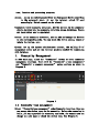
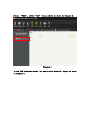
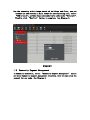
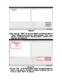
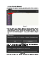
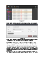
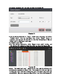
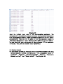
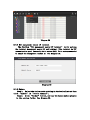
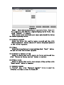
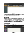
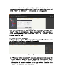
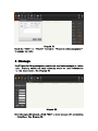
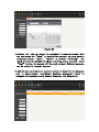
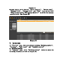
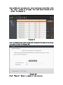
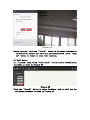
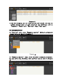
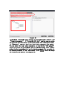
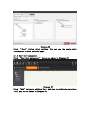
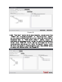
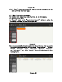
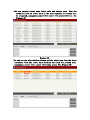
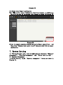
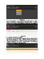
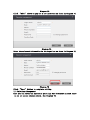
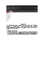
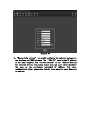
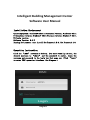
 Intelligent Building Management Center Software User Manual Installation Environment
Operating System:WindowsXP 32bit Professional version; WindowsXP 64bit
Professional version; Windows 7 32bit Ultimate version; Windows 7 64bit
Ultimate version.
Software Version:3.0.X
Running Environment:must install Net Framework 2.0,.Net Framework 4.0.
Operation Instruction
Click the “IBMC” software on desktop. (For first-time log-in user, the
default username is “admin” and the password is empty). Input the
username and password in the login box that pops out. Click “Login”
to enter IBMC operation interface. See Diagram 1.
Diagram 1 IBMC Operation Main Page:
Diagram 2
Personnel:the registration and management of the names of house-owner
and property management staff. After the personnel information is
included into system, the unlock password and IC card can be allocated
according to the personnel sheet under Access management section;
Message: send messages to house owners via Message publish function.
The device used to receive message can be designated. Also the previous
messages can be viewed and managed;
Intercom:able to call and have intercom with house owner. Also you can
monitor through the stair unit and fence unit;
Alarm:receive the alarm alert and repair requirement messages from
house-owner, view and manage the history alarm message in terms of alarm
time, location and processing progress;
Access: set up the unlock password for the designated device according
to the personnel sheet. Or set the relevant unlock IC card
accordingly. Unlock record can be viewed;
Community:build community structure. All the devices in the community
will be included into the community structure. Areas, buildings, floors
and room number can be appointed;
Device:in the community structure, you can add and manage the devices
on the corresponding node. You can check the device status, reset or
update the device, etc;
System : set up the system administrator account, the calling IP of
management center and all the relevant projects needed for connecting
with database.
1. Community Management
In IBMC main page, click the “Community” button to enter community
management interface. There will be “Community’s type management”
and “Community’s segment management” setup sections as shown in
Diagram 3.
Diagram 3
1.1 Community type management
Select “Community type management” under Community interface. Here you
can manage the device types in the community. Before the community is
built, you can supervise the community type node, for example you can
change the node name or check the device type. See Diagram 4.
Diagram 4
In the above diagram you can see the name of nodes are divided into 5
sections including “Area”, “Building”, “Unit”, “Floor” and
“Room”. The length of the node is defaulted as 2. It is not recommended
to amend the length of node. Click “Type”select box to select the
devices to be mounted.(Note: in the Type section, only fence unit and
center unit can be added to the “Area” node; No devices will be added
to the “Building” and “Floor” node; Only stair unit can be added
to the “Unit” node; Only villa outdoor unit or secondary confirmation
outdoor unit or indoor sub-unit can be added to the “Room” node.)
1.2 Build Community Structure
The community is in tree structure. The “IBMC” is the root node of the
whole community. All the community devices all under control of “IBMC”.
You can build one or more “Area” under “IBMC” node. And build one
or more “Building” under “Area” node. And build one or more “Unit”
under “Building” node. And build one or more “Floor” under “Unit”
node. And build one or more “Room Number” under “Floor” node. All
the superior and subordinate nodes are in one-to-one correspondence,
for example, you can only build “Unit” instead of “Room Number”
node under “Building” node.
Select “IBMC”, click “Add” button above as shown in Diagram 5.
Diagram 5
In the IBMC structure sheet, the newly-added node will appear as shown
in Diagram 6.
Diagram 6
You can add “Area” node under “IBMC” node. And add “Building” under
“Area” node. And add “Unit” under “Building” node. And add “Floor”
under “Unit” node. And add “Room Number” under “Floor” node. See
Diagram 7.
Diagram 7
For the community with a large amount of buildings and floor, you can
conduct the add section in bulk. Under the corresponding node, select
“Add in batch”, and then input the number to be added under “Multiply”.
Finally click “Confirm” button to complete. See Diagram 8.
1.3
Diagram 8
Community Segment Management
In Community interface, select “Community segment management” option
and enter Community segment management interface. Here you can setup the
segment for any node. See Diagram 9.
Diagram 9
Double click the “IBMC” in the above diagram. An extension sheet of
“Area” information will drop down. Double click the “Area” sheet
and then,an extension sheet of “Building and Unit” information will
drop down. See Diagram 10.
Diagram 10
Click the “Add” in the diagram above. Select the community node that
needs to setup segments, and input the segment and gateway that need
to be set. Click “Save” to complete.
1.4
Auto Generate Equipment
After you build the community structure, you need to generate devices as shown in
Diagram 11.
Diagram 11
Click the “Edit” and “Delete” button in the above Diagram,and you
will be able to amend and delete the device information. Click “Auto
Create Equipment” button, and then an indication page saying “Are
You Sure To Auto Create Equipment?” will pop out as shown in Diagram
12.
Diagram 12
Click “OK” button, and in indication page saying “Auto Create Equipment
Success” will pop out as shown in Diagram 13.
Diagram 13
After you click the “OK” button, the device auto generation process
will be done. The software will assign one indoor unit and one unit
outdoor unit for each room and unit automatically.
2. Device Management
2.1 Equipment Information
Under the “Device” menu, there are “Equipment info” section and
“Equipment upgrade” section. Select “Equipment info” to enter the
next page as shown in Diagram 14.
Diagram 14
In “Equipment Info”, you can add equipments. Under the corresponding
node, click“Add” to pop out the “Equipment Management” edit box to
add equipments. Select the equipment type and sub-unit number under the
node. The equipment IP can be the default value or be edited manually.
Click “Save” to complete.
Note : in the community structure, select the node that need to add
equipment. Stair unit can only be added on “Unit” node. Fence unit and
security unit can only be added on “Area” node.
2.2 Add Outdoor Unit
For example, if you want to add a unit outdoor unit for “Area1 Building1
Unit1”, firstly you should select “01Area 01Building 01Unit” node in
community structure. See Diagram 15
Diagram 15
Click “Add” button to pop out the following interface. See Diagram 16.
Diagram 16
Click “Save” button to complete the adding process. You can view the
information of the new outdoor unit in equipment info page.
2.3 Add Villa Outdoor Unit or Secondary Confirmation Outdoor Unit
If you need to add villa outdoor unit or secondary confirmation outdoor
unit, you will fail to input the local code because the villa outdoor
unit or secondary confirmation outdoor unit lack operation interface.
Therefore, management center is identified via the equipment’s MAC
address. So you need to enter the MAC address info of the corresponding
equipment when you setup villa outdoor unit or secondary confirmation
outdoor unit.
For example, if you want to add a secondary confirmation outdoor unit
for “01Area 01Building 01Unit 01Floor 01Room”, firstly you should
select “01Area 01Building 01Unit 01Floor 01Room” node in community
structure. See Diagram 17.
Diagram 17
Click “Add” button to pop out an interface as shown in Diagram 18.
Diagram 18
Click the rectangle slot next to “Type” in the above interface, and
select “secondary confirmation outdoor unit” from the drop-down list.
Click “Show Advanced” button to enter next interface as shown in
Diagram 19.
Diagram 19
In “Device MAC” slot, input the MAC address info of the corresponding
equipment. Click “Save” to complete the adding process. You can view
the information of the secondary confirmation outdoor unit in Equipment
info page. For the method to add villa outdoor unit please refer to the
one for secondary confirmation outdoor unit.
2.4 Add Indoor Unit
For example, if you want to add an indoor sub-unit for “01Area 01Building
01Unit 01Floor 01Room”, firstly you should select “01Area 01Building
01Unit 01Floor 01Room” node in community structure. See Diagram 20.
Diagram 20
After you select the node, click the “Add” button on the left, and the
following interface will pop out as shown in Diagram 21.
Diagram 21
Click the select slot next to “Type” in the above interface, and select
“Indoor unit” from the drop-down list. Click “Save” button to
complete, and then you will be able to view the information of the new
indoor unit in Equipment info page.
2.5 Export Local Code
After you add the equipments, click “Export local code” button, and
the system will extend an drop-down list as shown in Diagram 22.
Diagram 22
Select “All node local code” option in the list, and the software will
automatically generate an Excel file. Then setup the file name and the
storage path. There will be an indication after you export the local code
successfully. The newly-generated Excel file is as shown in Diagram 23.
Diagram 23
Input the 6-digit local code to the corresponding equipment. The
equipment will automatically request relevant configuration information
from the management center. After successful acquisition it will reboot
automatically. Then you will be able to view the equipment status in
“Equipment Management” page. System will be defaulted as auto-update.
You can check the real-time status of the equipment. If the equipment
is online, then you can conduct other operations.
2.6 Device Command
You can remote operate the terminal devices via Device Command. The main
device commands include six functions: “ Set management center IP
terminal”, “Update”, “Restore password”, “Reset”, “Restore to
factory setting” and “Reset unlock”. See Diagram 24.
Diagram 24
2.6.1 Set management center IP terminal
The function “Set management center IP terminal” is for setting
the terminal management center IP and terminal. This terminal is UDP
communication port. Currently it is set as 8805. It is not recommended
to amend the management center IP. See Diagram 25.
Diagram 25
2.6.2 Update
Step 1: Select the device needs updating in the device list and then
click “Update” in “Device command”;
Step 2: Click “Folder” button, and copy the latest update program
to the catalog folder. See Diagram 26.
Diagram 26
Step 3: Choose the corresponding unit type in its folder. There will
be an indication when there is no upgraded package in the folder. Then
click “Upgrade” to complete.
Note: please ensure consistent power supply and network flow during
the device upgrading process.
2.6.3 Restore password
Select the device that need to restore password and then click
“Restore password” button, and you will restore the project password
of the relevant equipment.
2.6.4 Reset
Select the device that need to reset and then click “Reset” button,
and you can reset the relevant equipment.
2.6.5 Restore to factory setting
Select the device that need to restore to factory setting and then
click “Restore to factory setting” button to complete.
2.6.6 Reset unlock
Select the device that need to reset unlock setting and then click
“Reset unlock” button to complete.
2.7 Equipment Upgrade
In “Device” menu, click “Equipment upgrade” button to enter the
following interface as shown in Diagram 27.
Diagram 27
There are two options including “Device upgrade manually” and “Device
auto upgrade. Please select according to actual needs.
3. Personnel
In Personnel menu, you can edit the content of “Owner management” and
“Property worker management”. After you set up the personnel sheet,
you will be able to assign unlock password and IC card according to Owner
personnel sheet in Access management. Or distribute operation access of
the relevant system according to Property worker personnel sheet.
3.1 Owner Management
In Personnel menu, select “ Owner management ” option to enter the
following interface as shown in Diagram 28.
Diagram 28
In “ Owner management ” menu, owners and their room number can be
one-to-one matched and registered. Record the identity and contact
information of the owner, select the “room” for adding the owner, and
click “Add” to add owner’s information as in Diagram 29.
Diagram 29
Input the relevant info of the owner in the pop-out box and then click
“Save”. Then it will indicate “Save successfully”. You can view it
in the Owner Management list. Click the “Edit” or “Delete” button
to amend owner’s info.
3.2 Property Worker Management
In Personnel menu, select “Property worker management” option to enter
the following interface as shown in Diagram 30.
Diagram 30
In “Property worker management” menu, you can register and manage the
info of community property workers. Record the identity info, family
address and contact info. Click “Add” button and then enter the
information of property workers in the pop-out box. Finally click
“Save” to complete. See Diagram 31.
Diagram 31
Click the “Edit” or “Delete” button in “Property worker management”
to manage the info.
4. Message
Intelligent building management center can send text messages to indoor
unit. Property worker can send community notice or local information
to the house-owner. See Diagram 32.
Diagram 32
Enter Message publish menu, click “Add” to enter message edit and sending
interface. See Diagram 33.
Diagram 33
In device list, you can select the equipment to receive massage. Here
you can choose one “Room” to receive the message; or group-send by
selecting several “Room”, “Floor” or several “Building”. The
check box will be checked for those receiving points selected. Click
“Send” button, the message will be saved and sent. Relevant messages
can be viewed in terminal devices.
To make it more convenient for property workers to supervise the messages
sent to house-owners, intelligent building management center is
equipped with message record inquiry function. See Diagram 34.
Diagram 34 Message inquiry can be done via “Device location”, “Message type”,
“Message title”, “Message title” and “Time”. Also you can click
“Show message details(Hide message details)” to decide show message
details or not. See Diagram 35.
Diagram 35 5. Intercom
In “Intercom” menu, there are options including “Building monitor”,
“Intercom”, “Call record” and “Community monitor”.
5.1 Building Monitor
In “Intercom” menu, click “Building monitor” button to enter the
following interface as shown in Diagram 36.
Diagram 36
Select the stair unit or fence unit to monitor. See Diagram 37.
Diagram 37
Click the “Monitor” button on the right and you will be able to monitor
(only the “online” devices). See Diagram 38.
Diagram 38
5.2 Intercom
IBMC can receive calls from indoor unit, stair unit and fence unit. It
can make a call to indoor unit and activate 2-way intercom.
5.2.1 Indoor Unit Calls IBMC
Intelligent Building Management Center will show the following interface
when an indoor unit calls IMBC. See Diagram 39.
Diagram 39
Click “Answer” button and you can have intercom with indoor sub-unit as
shown in Diagram 40.
Diagram 40
Click “Hang up” button to reject or stop intercom.
5.2.2 IBMC Calls Indoor Unit
When an IBMC calls an indoor unit, select the device to be called,click
the “Call” button on the right. Only those online devices can be
called. See Diagram 41.
Diagram 41
After the house-owner picks up the call and you will be able to have 2-way
intercom as shown in Diagram 42.
Diagram 42
Click “Hang up” button to reject or stop intercom.
5.2.1 Outdoor Unit Calls IBMC
When an outdoor unit calls the IBMC, IMBC will show the following
interface, which is the image captured by outdoor unit as shown in
Diagram 43.
Diagram 43
Click “Answer” button to have video intercom with outdoor unit. See
Diagram 44.
Diagram 44
During intercom, click the “Unlock” button in the above interface to
unlock for the outdoor unit that is in conversation with. Click “Hang
up” button to reject or stop video intercom.
5.3 Call Record
In “Intercom” menu, click “Call record” button to enter the following
interface as shown in Diagram 45.
Diagram 45
Click the “Search” button in above interface,and you will see the
following interface as shown in Diagram 46.
Diagram 46
In the above diagram, you call view previous call record. Also you can
conduct refined query of call record by the conditions such as
“Location”、“Start time”、“End time”、Type、
“User name”.
5.4 Community Monitor
In “Intercom” menu, click “Community monitor” button to add network
camera device as shown in Diagram 47.
Diagram 47
In “Community monitor” menu, select the node in community structure.
You can add in Area, Building, Unit and Floor node as shown in Diagram
48.
Diagram 48
Click “Add” to pop out “IPC management” slot. Input the IP address
that needs IPC installation. Then input relevant information in
“Location” slot. After that, select manufacture in the “Manufacturer
type” slot. Currently the supporting manufacturers include StarNet,
ahua, hikvision, UMD, HanBangGaoKe and Govty. Please enter password
of Username one by one according to IPC Manufacturer. See Diagram 49.
Diagram 49
After inputting the password of username, click “Save” to complete
adding IPC. You can view the newly-added IPC in Community monitor
interface. See Diagram 50.
Diagram 50
Select the IPC to monitor in the list. Click “Edit” or “Delete” button
to make amendment. See Diagram 51.
Diagram 51
Click “Monitor” button in the above interface to enter Monitor interface
as shown in Diagram 52.
Diagram 52
Click “Close” button to abandon Monitoring.
5. Access Management
In “Access” menu, there are two sections including “Door control
management” and “check unlock record”. Here you can designate unlock
password or setup the relevant unlock IC/ID card for corresponding
devices according to Owner personnel sheet. Unlock record can be checked.
5.1 Door control management
In this section, there are “Door password management”, “Door Card
management” and “Door fingerprint management”.
Click “Door control management” button to enter the following interface
as shown in Diagram 53.
Diagram 53
5.1.1 Door password management
Click “Door password management” button, See Diagram 54.
Diagram 54
Click “ Add” button to add “Door password”, then the following
interface will be shown as in Diagram 55.
Diagram 55
In the above “Password type” option, you can select from “Owner” and
“Property personnel”. In“Password valid date” option, you can setup
the password valid date so as to limit the unlock time to designated time.
In “Password” section, the first four digits represent room number.
You can enter the room number manually, or just click “All people”
option to locate the room number you need through nodes. Input 4-digit
number in the room number slot as the unlock password. You can only set
one unlock password for one room number. Click
button to setup
the valid unlock device. See Diagram 56.
Diagram 56
Click “ Save” button after setting. You can see the newly-added
information in Door password page.
5.1.2 Door Card management
Click “Door Card management” button as shown in Diagram 57.
Diagram 57
Click “Add” button to add Door Card. And then the following interface
will pop out as shown in Diagram 58.
Diagram 58
In the “Card type” section in the above interface, you can select from
“Owner” and “Property personnel”. In “Card valid date” option,
you can setup the unlock valid date so as to limit the unlock time to
designated time. In “ Card serial number ” option, connect the
card-reader of management center, and put the card on the card-reader
device. Click “Read IC” button, and the card number of the card
detected will be shown in the slot. Click “All people” option; locate
the device that needs to a card through the nodes. Click
button
to setup valid unlock device. See Diagram 59.
Diagram 59
Click “Save” button after setting. You can view the information of the
new card from Door Card page.
5.1.3 Door fingerprint management
The outdoor unit supporting this function is in development.
5.2 Unlock Record Query
In “Access” menu, click “check unlock record” button to enter the
following interface as shown in Diagram 60.
Diagram 60
Here you can search the unlock record of all unlock devices. You can search
by refined conditions on the left including “Legal unlock”, “Illegal
unlock”, “Location”, “Type”, “Start time”, “End time”, “User type”
and “User Name”, etc. Click “Search” button to view result as shown
in Diagram 61.
Diagram 61
6. Alarm Management
In “Alarm” menu, there are options including “Undealed alarm”, “Check
alarm record” and “Check or deal repair record”. See Diagram 62.
Diagram 62
6.1 Undealed alarm
Click “Undealed alarm” button and an interface will pop out as shown
in Diagram 63.
Diagram 63
You could click the “Deal” or “Delay Deal” button. The alarm interface
will be closed only after the alarm is dealt with or after you click
“Ignore All” button. You can check the alarm record and its processing
information via Alarm record query.
6.2 Check alarm record
Click “Check alarm record” button and an interface will pop out as shown
in Diagram 64.
Diagram 64
Click “Search” button to view alarm record as shown in Diagram 65.
Diagram 65
6.3 Check or deal repair record
Click “Check or deal repair record” button and an interface will pop
out as shown in Diagram 66.
Diagram 66
Click “Search” button and you can view “Check or deal repair record”
as shown in Diagram 67.
Diagram 67
Select the “service application” to be handled from the interface, and
then click “Deal service application” button to conduct the process.
6.4 Indoor Unit or Outdoor Unit Triggers Alarm
IBMC can receive alarms from indoor unit and outdoor unit. When the
security alarm of indoor unit or the door magnetic of outdoor unit
is triggered, management center will report with alarm info list. See
Diagram 68.
Diagram 68
You can see the alarm device address and the alarm type from the above
interface. When the indoor unit disables the alarm with kidnap code,
management center will report the kidnap alarm. See Diagram 69.
Diagram 69
6.4 House-owner Repair Application
When IBMC receive repair information from house-owners, an indication
box will pop out at the bottom right corner as shown in Diagram 70
Diagram 70
Select the repair record to be handled from the Repair record list, and
then click “Check or deal repair record” button to deal with the repair
application.
7. System Setting
In “System Setting” menu, there are three options including “Operator
management”, “Privilege management” and “System info setting”.
7.1 Operator Management
In System section, click “Operator management” button as shown in
Diagram 71.
Diagram 71
After you click you will enter the following interface. Click the “Add”
button on the interface to add new operator. And click “Edit” or “Delete”
button to edit or delete the information of operators. See Diagram 72.
Diagram 72
7.1.1 Setup System Default Password
For the first-time login system will recognize the user as System default
user with the username as “admin” and empty password. Before you use
IBMC, you should designate a password to secure the system safety. In
“Operator management” page, locate “Administrator” option and check
the box so as to select it. See Diagram 73.
Diagram 73
Click “Edit” above to pop out a new interface as shown in Diagram 74.
Diagram 74
Enter the relevant information in the input box as shown in Diagram 75.
Diagram 75
Click “Save” button to complete setting.
7.2 Privilege Management
Here you can setup the operation privilege for different account staff
so as to secure system safety. See Diagram 76.
Diagram 76
In “Please select role” section, you could select from “Property
Manager” or “Property Staff”. Then double click “IBMC” below to
extend a drop-down list, where you can setup the operation privilege for
different levels of staff.
7.3 System Info Setting
In “System info setting”, you can configure the relevant information
of servers and database for IBMC software. Only after these information
are setup will the IBMC software function normally. See Diagram 77.
Diagram 77
In “System info setting” you could configure the relevant parameters
for database and IBMC software. The “IBMC IP” must be the IP address
of the local computer. The “Server address” of the “Address Setting”
for terminal devices (including indoor unit and stair unit) should be
the same as the previously mentioned IP address. For other
configuration items, please use default value when its exact function
is unclear.